Worldwide Connectivity for the Internet of Things Through LoRaWAN


1
Department of Information Engineering, University of Padova, Via Gradenigo 6/B, 35131 Padova, Italy
2
Department of Electronic Systems, Aalborg University, Fredrik Bajers Vej 7 A3-A4, 9220 Aalborg, Denmark
*
Author to whom correspondence should be addressed.
†
These authors contributed equally to this work.
Future Internet 2019, 11(3), 57; https://doi.org/10.3390/fi11030057
Submission received: 17 January 2019
/
Revised: 10 February 2019
/
Accepted: 25 February 2019
/
Published: 2 March 2019
(This article belongs to the Special Issue 10th Anniversary Feature Papers)
Abstract
:The low-power wide-area network (LPWAN) paradigm is gradually gaining market acceptance. In particular, three prominent LPWAN technologies are emerging at the moment: LoRaWAN™ and SigFox™, which operate on unlicensed frequency bands, and NB-IoT, operating on licensed frequency bands. This paper deals with LoRaWAN™, and has the aim of describing a particularly interesting feature provided by the latest LoRaWAN™ specification—often neglected in the literature—i.e., the roaming capability between different operators of LoRaWAN™ networks, across the same country or even different countries. Recalling that LoRaWAN™ devices do not have a subscriber identification module (SIM) like cellular network terminals, at a first glance the implementation of roaming in LoRaWAN™ networks could seem intricate. The contribution of this paper consists in explaining the principles behind the implementation of a global LoRaWAN network, with particular focus on how to cope with the lack of the SIM in the architecture and how to realize roaming.
1. Introduction
The internet of things (IoT) is a well-known paradigm, established quite a few years ago. However, only in recent times the trend regarding the wireless connectivity for the IoT has been shifting from technologies based on short-range links and mesh topologies, to long-range, star-topology-based networks. Moreover, such a long-range IoT paradigm is taking two alternative directions: one for mission-critical applications, and one for the massive IoT. Therefore, in this respect we can distinguish between two families of wireless technologies that are playing now a key role:
- the low-power wide-area networks (LPWANs), which will serve the needs of the massive IoT for smart metering, remote monitoring and tracking, etc. [1]. Renowned examples of LPWANs are LoRaWAN™ and SigFox™ on unlicensed spectrum, and NB-IoT on licensed spectrum;
- the ultra-reliable low-latency communications (URLLC), serving the needs of mission-critical IoT for, e.g., smart manufacturing and autonomous driving. URLLC is mostly implemented in the context of the fifth-generation (5G) cellular network [2].
The focus of this paper is on massive IoT, and in particular on the network architecture principles of LPWAN technologies. One architectural feature that is recently gaining momentum is the support of roaming of IoT nodes between different networks. As a matter of fact, such a feature has been totally neglected before the emergence of LPWANs. Indeed, classical short-range IoT technologies like, e.g., ZigBee, Thread, 6LowPAN [3,4] are based on local networks run by either private or public operators, but spanning at most the area a city (even a large one, like London). However, the possibility of running such a legacy network for massive IoT in, e.g., a nationwide deployment is very hard—if not impossible at all. As a consequence, the possibility for a smart thing to migrate from a network to the other was simply not considered, and the support of roaming was neglected in the specification and in the implementations.
On the other hand, with the rise of the LPWANs, the aim is that of providing wireless connectivity for a massive number of things to areas of very different sizes, from a private network in a building to a nationwide IoT network. Therefore, the use cases for having the possibility to roam from one network to the other have actually been a distinctive characteristic of LPWANs. As a first example, let us consider an appliance exploiting a LoRaWAN™ communication node to enable preventive maintenance programs. In order for the appliance manufacturer to effectively sell its products in many countries and markets around the world having LoRaWAN™ coverage, he needs a worldwide connection plan from the local LoRaWAN™ network operator. The feature requested by the appliance vendor is technically known as a roaming plan, and cannot be provided by traditional mesh-based technologies like ZigBee, Thread and 6LoWPAN. This is the motivation that led us to deal with features like roaming in this paper, since this matter is essential for the full exploitation of the IoT possibilities.
Among the LPWANs, the focus will be specifically on LoRaWAN™ networks because of the following reasons.
- As NB-IoT works on licensed frequencies, is based on subscriber identification module (SIM) and run by traditional cellular operators, it should benefit from the traditional roaming features of the mobile networks.
- Sigfox™ is based on a single worldwide network, thus the roaming concept does not apply. Looking more in depth, however, one may notice that the roaming is effectively applied as a “feature” of the business model SigFox™ is using. As a matter of fact, such a business model resembles quite closely the one of franchising, where—for example—in Italy the company NetTrotter, which is part of the EITowers group, is the franchisee of SigFox France. NetTrotter is deploying the SigFox™ network in Italy, but Italian customers see only the SigFox logo and services, and all the back-end systems are run by SigFox France. In this way, they are creating a global unique network for the customer, and the roaming issue becomes purely a matter of sharing the revenues between the different local companies and the mother company in France.
As a consequence, the “true” roaming for LPWANs can be seen—at the time of writing—only in LoRaWAN™, since the LoRaWAN™ operators are independent one another and LoRaWAN™ end nodes do not have any SIM.
The rest of the paper is organized as follows. Section 2 provides an introductory overview of LoRaWAN™ networks. Section 3 describes the different functional elements in the LoRaWAN™ back-end. In Section 4, we give an example of a very important procedure, i.e., the way an end device joins a LoRaWAN™ network; by providing such an example we want to highlight the interaction of the various functional elements in LoRaWAN™ networks. Then, the rationale of LoRaWAN™ back-end architecture with the objective of global roaming for massive IoT is discussed in Section 5. Finally, in Section 6 we draw the conclusions of this work.
2. A Preliminary Overview of the LoRaWAN™ System
As for almost any communication network (see for example Chapter 1 of [5]), LoRaWAN™ networks can be divided in two parts:
- The radio access network part, composed of terminals (which are called end devices in the context of LoRaWAN™ networks) and gateways (GW);
- The back-end part, that is, the “core network” of LoRaWAN™ networks, composed of the network server (NS). Actually, the back-end is much more complicated than a simple entity as the NS, and will be further examined in the next sections.
As far as the radio access network part (i.e., the wireless links between end devices and GWs) is concerned, for the scope of this paper, which is dealing with the “core network” of LoRaWAN™, it suffices to say that (see Figure 1)
- packets are exchanged in both directions (uplink and downlink);
- the GWs are transparent devices. This means that they receive/transmit the packets over the radio interface and they receive/forward these packets from the NS without any intervention on the packets themselves.
The complete intelligence of the LoRaWAN™ network resides in the Network Server, which is, for example, in charge of de-duplicating the received packets: indeed, as shown in Figure 1, a single packet can be received by multiple GWs. More detailed descriptions of the radio interface and the medium access control (MAC) layer can be found in [6,7], respectively.
We want to remark that this paper refers only to the latest version (i.e., version 1.1) of the LoRaWAN™ system specification [8]. The previous versions of the specifications—to which, e.g., [7] is referring—did not include a complete and verified description of the roaming feature, which is the focus of this paper.
3. The Back-End of the LoRaWAN™ System
The architecture shown in Figure 1 can scale without problems as the network size grows, including nationwide deployments. For example, a national utility provider may deploy GW over an entire country, connecting all of them to a unique NS that manages the entire LoRaWAN™ network. Of course, the actual implementation of the NS needs to take into account issues like, e.g., fault tolerance, scalability, capability of handling a huge number of messages, and these challenges are particularly important in a national network setup.
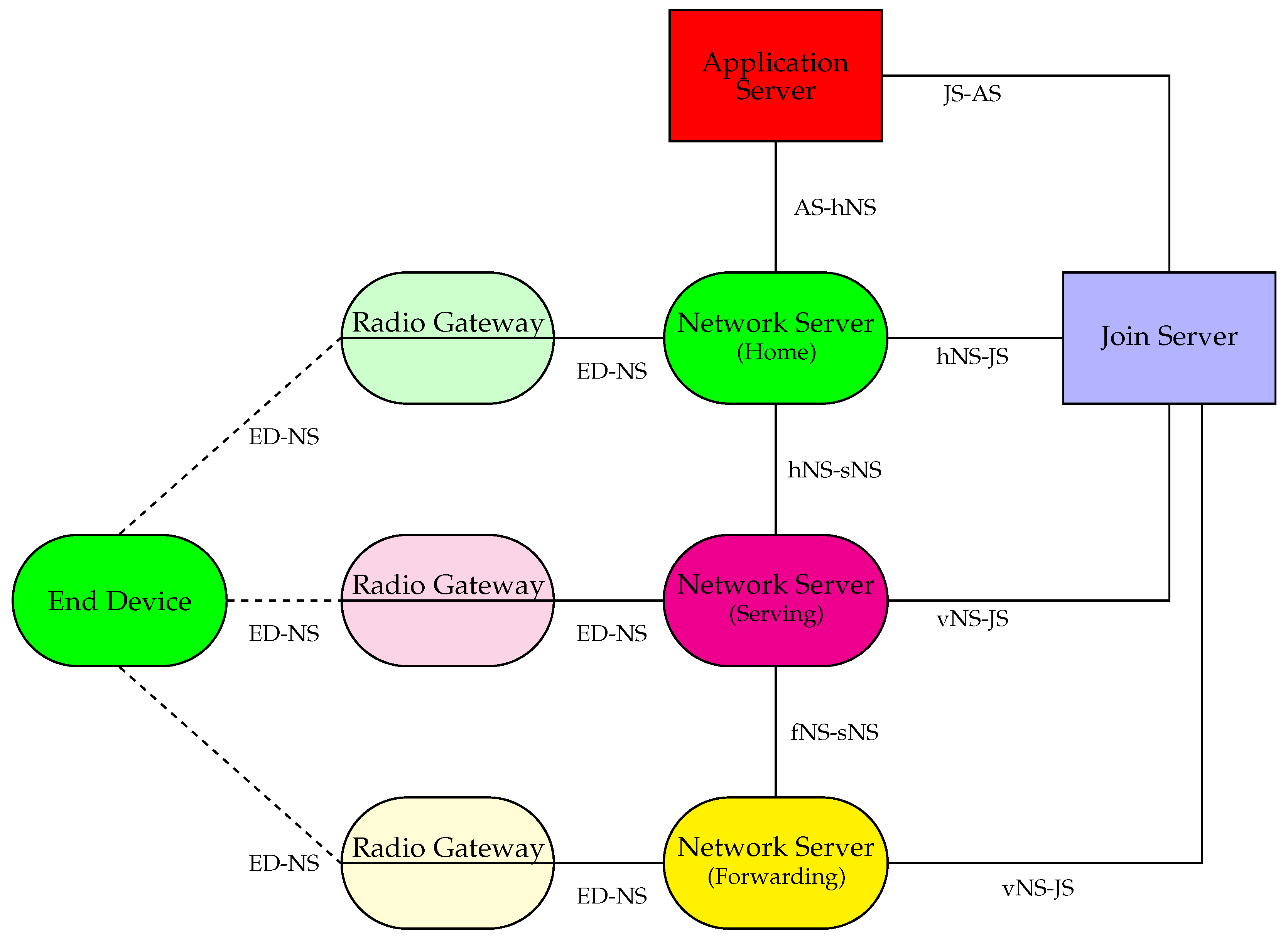
However, as pointed out in the Introduction, a device may need to roam between different networks, and the architecture of Figure 1 cannot cope with this requirement. As a consequence, a complete architecture that is capable of supporting a global/worldwide roaming has been included in the latest specification of the LoRaWAN™ system. A graphical representation of such an architecture is provided in Figure 2.
Going deep into the details of the procedures involving the different entities in the architecture would be too heavy, and also quite boring. Thus, in the following of this paper we will list all the entities with a light description of each of them. In particular, in the remainder of this section we will go through the three kinds of NS. Moreover, let us remark that two further entities are introduced in Figure 2: the application server and the join server, whose functions will become clear in the description of how an end device joins a LoRaWAN™ network, which will be given in the next section.
Three Different Types of Network Servers
As shown in Figure 2, there are three different types of NS:
- the home NS. It is the NS of the network operator the end device belongs to;
- the serving NS. It is the NS of an operator whose network is taking care of end nodes which are out of coverage of their own home network. It performs all of the functions of the home NS, as far as the MAC protocol is concerned, handling the so-called “active roaming” of the end device. We observe that the term “serving NS” is often used in a more general sense in the LoRaWAN™ specification. In particular, when the end node is under the control of the home NS, the home NS takes the role of serving NS as well. Thus, in this case the distinction between home NS and serving NS is purely logical, without any actual consequence on the procedures and protocols;
- the forwarding NS. It is the NS of an operator whose network may have, for example, a radio coverage overlapping with the home network of some end devices. It is transparent, and forwards/receives the traffic to/from the end devices through the GWs attached to it. It handles the so-called “passive roaming”.
We want to remark that the connection (especially, the MAC protocol) between the end node and the network is always managed by the serving NS, recalling that it coincides to the home NS in case there is no actual roaming and the end device is in its home network. Indeed, in case the end node is connected to a forwarding NS, the forwarding NS is transparent and the connection is redirected towards the serving NS (or to the home NS, in case they coincide). The specification for the MAC protocol is contained in [8].
4. How an End Device Joins a LoRaWAN™ Network
In this section, we will examine some key procedures (e.g., how an end node is activated) and, by means of flow charts, we will be able to give a short overview also of the security aspects of the LoRaWAN™ architecture.
Understanding how a node enters a LoRaWAN™ network is the best example to get a quick and clear understanding of the LoRaWAN™ architecture and its key principles:
- security without SIM card;
- separate security and confidentiality between control/network-data and user-data. Indeed, the user data are encrypted with keys which are not known to the network operator, while the control commands (e.g., the MAC commands) are encrypted with keys which have nothing to do with the keys used to encrypt user data.
According to the LoRaWAN™ specification, a node can enter the network in two ways:
- activation by personalization (ABP);
- over the air activation (OTAA).
At a very high level, ABP is such that all the security-related items are installed in the end device at the time of fabrication/commissioning, and cannot be changed afterwards. On the other hand, with OTAA, some root keys are installed at the commissioning stage, but the actual security keys used in the communication (both of network commands and user data) are derived in a secure way at the time the end device enters the network. Those keys are session-specific, and they are renovated from time to time (e.g., on a daily basis) to increase the security.
In this paper, we only consider the OTAA procedure, since it is the one recommended by the LoRa alliance, and it is the most secure. According to the OTAA procedure, an end device enters a network by sending a specific MAC command, i.e., a join-request command, which triggers the whole procedure of entering the network. Other MAC commands can be used from the network side, according to the specifications, in the process of an end device joining a network. In particular, rejoin-request type 1 and join-accept are MAC commands used in the joining process. The “rejoin” is used—in a broad sense—to force the renewal of the session keys. As a matter of fact, although the whole join process is believed to be secure, renewing the session keys is believed to make it even more secure in case the session keys get compromised.
In the following, we will review the security items of a LoRaWAN™ end device before and after joining the network.
4.1. Keys in an End Device before Joining the Network
After commissioning, an end device of a LoRaWAN™ network stores in a secure way the following set of keys:
- The JoinEUI. It is a global application identifier (ID) in the IEEE EUI64 address space (standard for layer-2 port identification released by IEEE. The address space utilizes 64 bit. For more information, see https://standards.ieee.org/products-services/regauth/index.html) that uniquely identifies the join server that assists the end device in the processing of the join procedure and the session keys derivation;
- The DevEUI. It is another global ID in the IEEE EUI64 address space that is used to uniquely identify the end device;
- The NwkKey. It is a AES-128 root key [9] specific to the end device, which is assigned to the end device during fabrication;
- The AppKey. It is another AES-128 root key [9] specific to the end device that is assigned to the end device during fabrication.
4.2. Keys in an End Device after Joining the Network
On top of the aforementioned keys, after the end device successfully joins a LoRaWAN™ network, the following additional set of keys are stored in the end device in a secure way:
- the NwkSEncKey. It is used to encrypt the signaling traffic;
- the AppSKey. It is used to encrypt the end device user traffic;
- the SNwkSIntKey and FNwkSIntKey. They are used to calculated the message integrity code (MIC) for the signaling traffic;
- the JSIntKey. It is used to calculate the MIC for rejoin-request type 1 messages and join-accept answers;
- the JSEncKey. It is used to encrypt the join-accept triggered by a rejoin-request;
- the end device DevAddr. It consists of 32 bits and identifies the end device within the current network. The DevAddr is allocated by the NS of the end device.
4.3. Flow Chart of the Join Procedure in the Non-Roaming Case
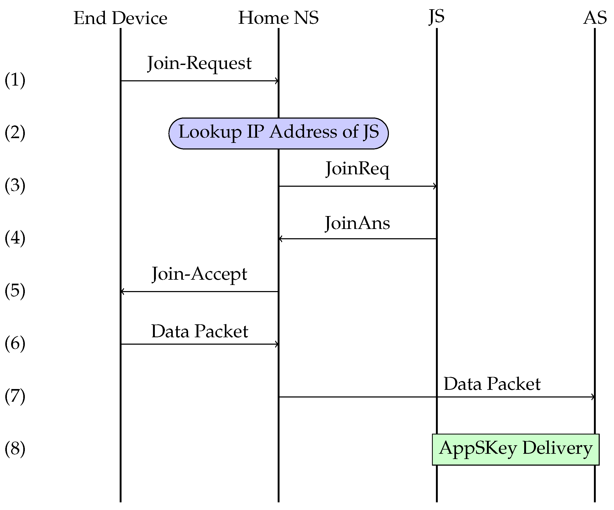
We are now providing a comprehensive example of the procedure an end device has to undergo in order to join its home network. The flow chart of such a procedure is provided in Figure 3, and it consists of the following steps.
- (1)
- The end device sends via LoRa radio link(s), i.e., through GW(s), a join-request message over the air and, being under the coverage of the home network, the message will reach the Home NS.
- (2)
- (3)
- The home NS passes the request as a JoinReq to the join server previously identified, including the DevEUI and other relevant parameters.
- (4)
- The join server, having all the necessary keys, derives the session keys for the control data and provide the NS with them.
- (5)
- The NS replies to the end device with a join-accept (via the radio interface, i.e., via the GWs) and sets all of the radio parameters.
- (6)
- A user data packet is sent (via the radio interface, i.e., via the GWs) to the NS as a JoinAns.
- (7)
- The network server, being the received packet made of user data, forwards it to the application server.
- (8)
- The application server gets the session keys for user data from the join server and decrypts the message making it available to the application layer.
4.4. Flow Chart of the Join Procedure in Case of Roaming
In contrast to the above example, we are now providing an example of the procedure an end device has to undergo in order to join a visiting network (or, equivalently, serving network), i.e., a network to which an end device is attached when it is out of coverage of its home network, thus in roaming. As a preliminary assumption, we consider that the regulation of the place where the device is roaming and the radio frequency parameters are the same as those in the country of origin. For example, let us consider the case of a device from a given European country, roaming into another European country. If the parameters [11] were not the same, there would be no way for the end device to retrieve the new radio frequency parameters. In fact, it is up to the manufacturer to build and certify end devices which are compliant with the regulations of the regions where they have been approved to operate. Moreover, the user of such a device needs to instruct it about the region wherein it is operating via some hardware switches or other means.
The flow chart of such a procedure is provided in Figure 4, and it consists of the following steps.
- (1)
- The end device sends via LoRa radio link(s), i.e., through GW(s), a join-request message over the air and, not being under the coverage of the home network, the message will reach a visiting NS.
- (2)
- (3)
- The visiting NS asks the join server the address of the home NS for the specific end device.
- (4)
- The join server provides the address of the home NS for the specific end device to the visiting NS.
- (5)
- The visiting NS asks all the information available to the home NS about the specific end device to be forwarded to it.
- (6)
- The visiting NS gets all the information available to the home NS about the specific end device.
- (7)
- The visiting NS asks the home NS of the specific end device to take control of the end device itself and possibly to host the end device in its network.
- (8)
- The home NS passes the request as a JoinReq to the join server previously identified, including the DevEUI and other relevant parameters.
- (9)
- The join server, having all the necessary keys, derives the session keys for the control data and provide the home NS with them as a JoinAns.
- (10)
- The home NS forward the session keys to the visiting NS.
- (11)
- The visiting NS replies to the end device with a join-accept (via the radio interface, i.e., via the GWs) and set all of the radio parameters.
- (12)
- A user data packet is sent (via the radio interface, i.e., via the GWs) to the visiting NS.
- (13)
- The visiting NS, being the received packet made of user data, forwards it to the application server.
- (14)
- The application server gets the session keys for user data from the join server and decrypts the message making it available to the application layer.
One can see from Figure 4 that the procedure for an end device to join a visiting network is not much more complicated than the one for the home network, as just a few more signaling messages are involved.
A further remark is that, apart from the restriction to use the same radio frequency regulations, the visiting network can be anywhere in the world: no notion of distance is involved with respect to the home network.
A final remark is related to the join server. As per the back-end specification [10], the LoRa Alliance is providing an IP based infrastructure allowing the different owners of the end devices to use different join servers, provided by third parties (as the security issues related to such a network element are quite stringent) which are usually well accustomed to provide certificates and similar trusted elements. Obviously, any join server will be designed not only with the security constraint in mind but also, for example, with the availability constraint, leading most likely to a federated/distributed architecture.
5. The Rationale of LoRaWAN™ Architecture for a Global Roaming of Things
Having introduced the join procedure for an end device, we can now describe what a customer should do before the node is switched on a certain network. In other words, so far we assumed the different servers (in particular, the join server) know all the relevant security keys. The question we ask ourselves in this section is:
“How do the servers get to know the keys?”
By answering this question, the crucial enabling characteristics of the LoRaWAN™ architecture for a global roaming will become apparent:
- having a trusted third-party repository (i.e., the join server) for the original keys of an end device which can be reached by any LoRaWAN™ network;
- having the home NS that knows the details of the subscription for an end device;
- having an application server to which the data generated by the end device are delivered, and to which the user data intended to be delivered to the end device must be provided.
Let us consider a customer that wants its end device to work on a certain LoRaWAN™ network with roaming capabilities (which, of course, depend on the deals his network operator has with other network operators, like in cellular phones). They must first provide the join server with the following information:
- the DevEUI;
- the AppKey;
- the NwkKey;
- the home NS identifier;
- the application server identifier.
The transfer of this information is usually done via some out-of-band procedure, i.e., not using the LoRaWAN™ network. Usually companies running the join server(s) provide, for example, a secure web portal where customers can upload the information for a single end device or for a batch of devices using a file with an agreed upon file format.
Now, the whole rationale of LoRaWAN™ architecture is clear, and can be described in the following points.
- The join server is the owner of the secret keys of each end device. It is not part of any LoRaWAN™ network operator, and since it is a crucial part of the architecture it is supposed to be run by a trusted third party (different from the operator). The join server releases the session keys to the application server and the home NS (and then to the visiting NS in case of roaming, see Figure 4), so that the original secret keys never get compromised. That is the motivation of recommending to renew the session keys, just in case an attacker could get hold of the session keys.
- The network server of the home network or a visiting (serving) network can get its session keys once again from the join server. We want to remark that the DevEUI is sent in clear text to the home NS (via the GWs) or the visiting NS (in case of roaming), which then can interrogate the join server and ask for the specific session keys.
- The home or visiting NS is finally able to direct and receive the user information to the right application server, since the home or visiting NS can get to know the identifier of the application server, as said above. Furthermore, the application server can get the session key to decrypt/encrypt the traffic from/to end device from the join server.
The major point of the presented architecture is to
- not give the secret keys to the network operators and applications servers, but deliver them to a trusted third party, enabling the roaming between different network operators;
- decoupling the security of the control information (e.g., MAC commands, for which the end point is the NS) and the user information (for which the end point is the application server).
6. Conclusions
In this paper, we presented the architecture of the back-end of the LoRaWAN™ system, which is often neglected in literature. The LoRaWAN™ network architecture allows for a peculiar feature among the systems for massive IoT in unlicensed frequency band: it allows global roaming of end nodes between different operators without requiring any SIM. Such a distinctive attribute was introduced in the latest version of LoRaWAN™ specification, and represents a remarkable achievement for this technology. The possibility of global roaming worldwide, alongside with other well-known characteristics such as very low power consumption, localization capability, and low cost, makes the LoRaWAN™ system a prominent candidate for a global interoperable system for the massive IoT.
Author Contributions
conceptualization, L.V. and M.C.; methodology, L.V. and M.C.; writing—original draft preparation, L.V. and M.C.; supervision, L.V.
Funding
This research received no external funding.
Conflicts of Interest
The authors declare no conflict of interest.
Abbreviations
The following abbreviations are used in this manuscript:
| ABP | Activation by personalization |
| AS | Application server |
| IEEE EUI64 | IEEE extended unique identifier—64-bit address space |
| GW | Gateway |
| ID | Identifier |
| JS | Join server |
| LPWAN | Low-power wide-area network |
| MAC | Medium access control |
| NB-IoT | Narrowband internet of things |
| NS | Network server |
| OTAA | Over-the-air activation |
| URLLC | Ultra-reliable low-latency communications |
References
- Ayoub, W.; Samhat, A.E.; Nouvel, F.; Mroue, M.; Prévotet, J. Internet of Mobile Things: Overview of LoRaWAN, DASH7, and NB-IoT in LPWANs standards and Supported Mobility. IEEE Commun. Surv. Tutor. 2018. [Google Scholar] [CrossRef]
- Li, Z.; Uusitalo, M.A.; Shariatmadari, H.; Singh, B. 5G URLLC: Design Challenges and System Concepts. In Proceedings of the 2018 15th International Symposium on Wireless Communication Systems (ISWCS), Lisbon, Portugal, 28–31 August 2018; pp. 1–6. [Google Scholar]
- Samuel, S.S.I. A review of connectivity challenges in IoT-smart home. In Proceedings of the 2016 3rd MEC International Conference on Big Data and Smart City (ICBDSC), Muscat, Oman, 15–16 March 2016; pp. 1–4. [Google Scholar]
- Rzepecki, W.; Iwanecki, Ł.; Ryba, P. IEEE 802.15.4 Thread Mesh Network—Data Transmission in Harsh Environment. In Proceedings of the International Conference on Future Internet of Things and Cloud Workshops (FiCloudW), Barcelona, Spain, 6–8 August 2018; pp. 42–47. [Google Scholar]
- Benvenuto, N.; Zorzi, M. Principles of Communications Networks and Systems; John Wiley and Sons Ltd.: Chichester, UK, 2011. [Google Scholar]
- Vangelista, L. Frequency Shift Chirp Modulation: The LoRa Modulation. IEEE Signal Process. Lett. 2017, 24, 818–821. [Google Scholar] [CrossRef]
- Centenaro, M.; Vangelista, L.; Zanella, A.; Zorzi, M. Long-range communications in unlicensed bands: The rising stars in the IoT and smart city scenarios. IEEE Wirel. Commun. 2016, 23, 60–67. [Google Scholar] [CrossRef]
- LoRaWAN™ Specification v1.1. Available online: https://lora-alliance.org/resource-hub/lorawantm-specification-v11 (accessed on 16 December 2018).
- Daemen, J.; Rijmen, V. The Design of Rijndael AES—The Advanced Encryption Standard; Springer: Berlin/Heidelberg, Germany, 2002. [Google Scholar]
- LoRaWAN™ Back-End Interfaces v.1.0. Available online: https://lora-alliance.org/resource-hub/lorawantm-back-end-interfaces-v10 (accessed on 16 December 2018).
- LoRaWAN™ Regional Parameters v.1.1. Available online: https://lora-alliance.org/resource-hub/lorawantm-specification-v11 (accessed on 16 December 2018).
Figure 1.
The architecture of a LoRaWAN™ network including the access part and back-end part. Notice that the “yellow” end device is “connected” to two distinct gateways (GW).
Figure 1.
The architecture of a LoRaWAN™ network including the access part and back-end part. Notice that the “yellow” end device is “connected” to two distinct gateways (GW).

Figure 2.
The architecture of the LoRaWAN™ system.

Figure 3.
Flow chart of operations for joining the home network. JS and AS denote the join server and the application server, respectively.
Figure 3.
Flow chart of operations for joining the home network. JS and AS denote the join server and the application server, respectively.

Figure 4.
Flow chart of operations for joining a visiting network. JS and AS denote the join server and the application server, respectively.
Figure 4.
Flow chart of operations for joining a visiting network. JS and AS denote the join server and the application server, respectively.

© 2019 by the authors. Licensee MDPI, Basel, Switzerland. This article is an open access article distributed under the terms and conditions of the Creative Commons Attribution (CC BY) license (http://creativecommons.org/licenses/by/4.0/).
Share and Cite
MDPI and ACS Style
Vangelista, L.; Centenaro, M. Worldwide Connectivity for the Internet of Things Through LoRaWAN. Future Internet 2019, 11, 57. https://doi.org/10.3390/fi11030057
AMA Style
Vangelista L, Centenaro M. Worldwide Connectivity for the Internet of Things Through LoRaWAN. Future Internet. 2019; 11(3):57. https://doi.org/10.3390/fi11030057
Chicago/Turabian StyleVangelista, Lorenzo, and Marco Centenaro. 2019. "Worldwide Connectivity for the Internet of Things Through LoRaWAN" Future Internet 11, no. 3: 57. https://doi.org/10.3390/fi11030057
Note that from the first issue of 2016, this journal uses article numbers instead of page numbers. See further details here.