VNF Placement Optimization at the Edge and Cloud †


1
Department of Software and Information Technology Engineering, École de Technologie Supérieure, Montréal, QC lH3C1K3, Canada
2
Department of Electrical Engineering and Computer Science, Pennsylvania State University, State College, PA 16801, USA
3
Department of Systems and Computer Engineering, Carleton University, Ottawa, ON K1S 5B6, Canada
*
Author to whom correspondence should be addressed.
†
This paper is an extended version of our paper published in IEEE Conference on Network Softwarization and Workshops, 25–29 June 2018, Montreal, QC, Canada.
‡
Current address: 1100, rue Notre-Dame Ouest, Montréal, QC H3C 1K3, Canada.
Future Internet 2019, 11(3), 69; https://doi.org/10.3390/fi11030069
Submission received: 8 February 2019
/
Revised: 4 March 2019
/
Accepted: 5 March 2019
/
Published: 9 March 2019
(This article belongs to the Special Issue Software Defined Networking (SDN) and Network Function Virtualization (NFV))
Abstract
:Network Function Virtualization (NFV) has revolutionized the way network services are offered to end users. Individual network functions are decoupled from expensive and dedicated middleboxes and are now provided as software-based virtualized entities called Virtualized Network Functions (VNFs). NFV is often complemented with the Cloud Computing paradigm to provide networking functions to enterprise customers and end-users remote from their premises. NFV along with Cloud Computing has also started to be seen in Internet of Things (IoT) platforms as a means to provide networking functions to the IoT traffic. The intermix of IoT, NFV, and Cloud technologies, however, is still in its infancy creating a rich and open future research area. To this end, in this paper, we propose a novel approach to facilitate the placement and deployment of service chained VNFs in a network cloud infrastructure that can be extended using the Mobile Edge Computing (MEC) infrastructure for accommodating mission critical and delay sensitive traffic. Our aim is to minimize the end-to-end communication delay while keeping the overall deployment cost to minimum. Results reveal that the proposed approach can significantly reduce the delay experienced, while satisfying the Service Providers’ goal of low deployment costs.
1. Introduction
In recent years, with the unprecedented growth of user data traffic, network services are becoming more diverse and dynamic [1]. Network Function Virtualization (NFV) is a novel networking paradigm that has become a key enabling technology for delivering such services. Specifically, NFV through the Service Chaining (SC) model [2] can provide the necessary flexibility to offer a large range of network services tailored to the needs of the end users.
To reap the benefits introduced by NFV, usually other technologies are also utilized. For example, Cloud Computing and NFV are tightly coupled towards providing Virtualized Network Functions (VNFs) typically instantiated as Virtual Machines (VMs) on data centers remote from the end-users. Nonetheless, following the evolution of recent trends in networking, NFV and Cloud Computing can also be interconnected with other emerging technologies, such as the Mobile Edge Computing [3], Internet of Things (IoT), and 5G towards providing the necessary tools of building a service-centric future Internet architecture.
This model follows recent trends of service provisioning, where services are moving from a host-centric to a data-centric model, in which the computational resources are repositioned closer to the end users [4,5]. This can be enabled by the MEC layer that provides small-scale Cloud Computing capabilities close to the end-users. Hence, the mix of all the above technologies is expected to essentially benefit from the proximity and elasticity of the programmable network resources that MEC offers, creating a new communication era.
The immense benefits and opportunities introduced by the edge concept urged major international initiatives to standardize this paradigm. For example, the European Telecommunication Standards Institute (ETSI) developed the Mobile Edge Computing (MEC) arhicecture [6], the OpenFog Consortium, the Fog Computing architecture [7], and National Institue of Standards and Technology (NIST), the Fog computing conceptual architecture [8]. Both MEC and Fog computing introduce the same concept of bringing cloud computing capabilities at the edge of the network; however, they include slightly different architectures. Both platforms utilize a distributed paradigm to provide low latency, high communication rates, and mobility support. However, Fog computing focuses on the infrastructure perspective while the Edge computing on things, pushing computing capabilities closer to the mobile devices in radio access networks (RAN) [9,10]. In this current work, since the emphasis is on the traffic generated by the IoT layer, we are using the MEC definition as our Edge Computing solution.
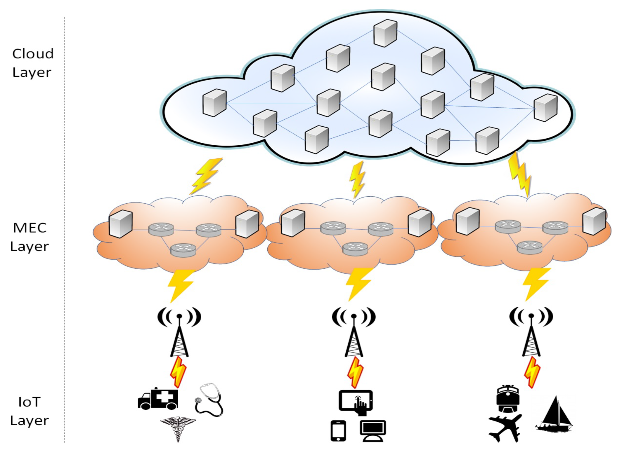
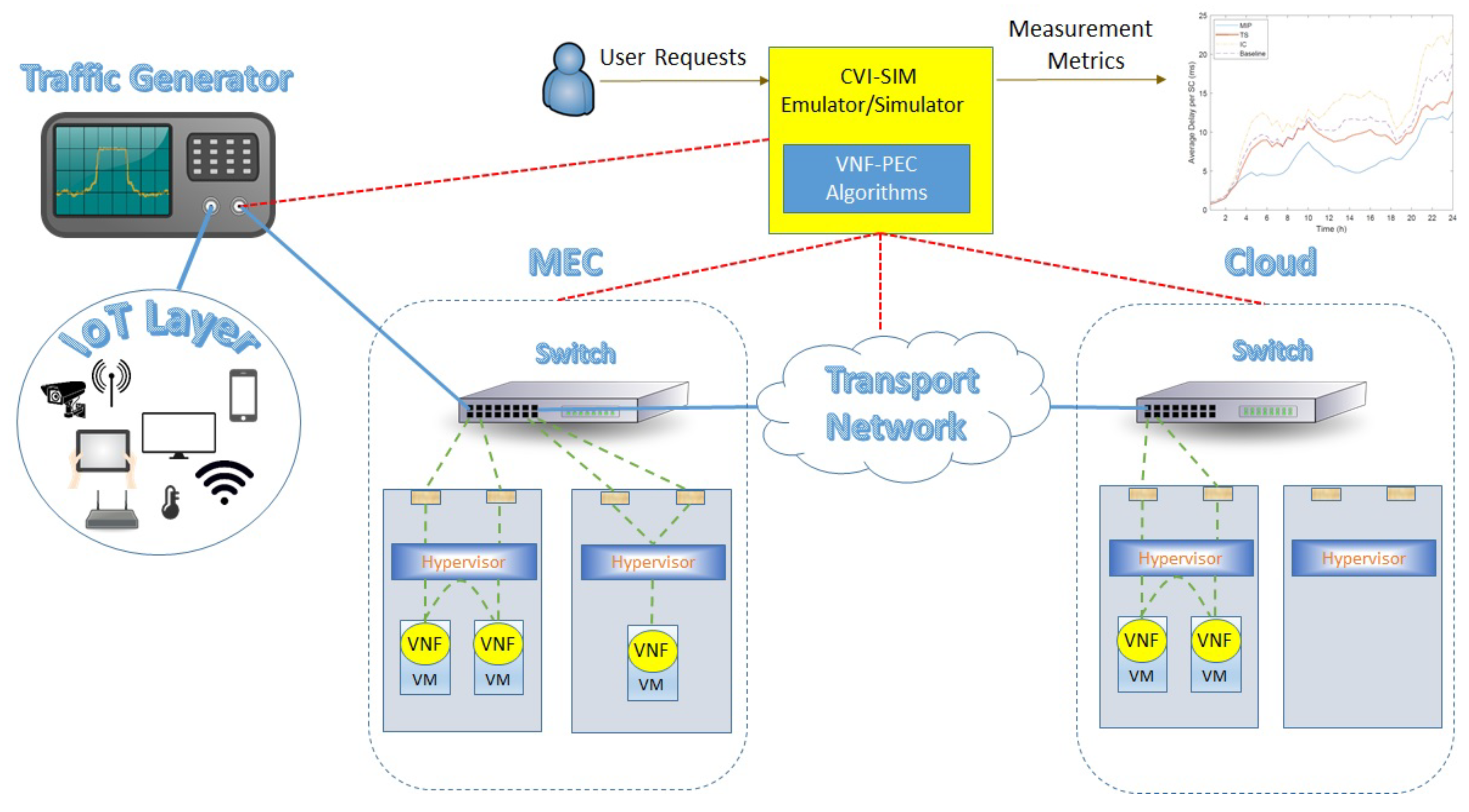
An example of such a scenario is cloud-based managed services for IoT applications (Figure 1). In this case, multiple IoT devices can generate huge amounts of traffic. This traffic can be routed through appropriate IoT gateways located at the edge of the network to a cloud environment consisting of multiple data centers. Hence, according to the amount of data generated by the IoT devices and the type of network services that are required to be applied, appropriate Service Chains (SCs) must be deployed in the MEC and Cloud infrastructures. At the same time, the generated traffic has specific requirements in terms of bandwidth and overall delay that can further guide the deployment of the SC. For example, for mission critical IoT applications, SCs should be deployed in the MEC taking advantage the close proximity to the IoT layer and, thus, lower latency is introduced. However, more resource intensive applications can benefit from the abundant and reliable resources in the Cloud.
The deployment of SCs essentially amounts to solving the problem of finding the underlying physical resources to instantiate the various VNFs comprising the SCs. A problem also known as the VNF Placement problem [11]. One major concern when solving the VNF Placement problem in such an environment is how to efficiently utilize the resources between the MEC and Cloud infrastructures in order to reconcile the conflicting goals of latency performance and deployment cost. This is a major challenge even if the Cloud was the only infrastructure available. For example, a Service Provider (SP) needs to balance the conflicting goals of minimizing the cloud resources used (e.g., for reducing the overall deployment cost) and minimizing the end-to-end delay for meeting pre-specified service-level agreements (SLA) [12,13]. However, minimizing the number of used servers can lead to an over-utilization of the server resources that can have a serious effect on the overall network delay [14].
The existence of both the MEC and Cloud creates an extra level of complexity when trying to balance the two particular metrics. On the one hand, utilizing the resources of the MEC can significantly reduce the perceived propagation delay. However, the MEC has a limited amount of resources and over-provisioning can lead to overutilization of the underlying infrastructure. On the other hand, the Cloud has many more available resources, but are usually remote from the IoT devices adding delay overhead. Furthermore, there are additional constraints that should be taken into consideration during the deployment of the SCs. For example, a subset of VNFs may come with location constraints. In this case, some VNFs must be deployed at the reliable and more resource powerful Cloud Computing layer (e.g., video optimization, deep packet inspection [15]), while others need to be instantiated close to the end users at the MEC (e.g., network address translation-NAT, firewall, traffic prioritazion) [4,16].
The topological characteristics of the SC can impose further limitations. Until now, most of the existing works assume that an SC is a simple line sequentially connecting several VNFs. However, more realistic scenarios include topologies with bifurcated paths (i.e., service graphs) [17]. Furthermore, the rate of the data can change according to the type of VNF processing that is applied. For example, a firewall can drop untrusted data streams resulting in flows with lower data rate, and video rendering VNFs can change the encoding of the traffic leading to higher/lower data rates [18]. These are factors that should also be considered, especially in a delay sensitive environment such as IoT.
To this end, we propose a novel resource allocation strategy to reconcile the conflicting goals of concurrently minimizing overall deployment costs and delays. In contrast with other existing approaches, we take into consideration a realistic scenario, incorporating a complete set of constraints, while we extend our framework and incorporate new directions in an intermix of different platforms and requirements.
The main contributions of the paper are listed as follows:
- Extend the VNF Placement problem taking into consideration the existence of both the Edge and Cloud infrastructures (VNF Placement at the Edge and Cloud VNF-PEC).
- Introduce an optimal placement algorithm formulated as a Mixed Integer Programming problem and a sub-optimal but fast approach based on the Tabu Search meta-heuristic.
- Take into consideration realistic SC topologies with features that can modify the incoming and outgoing data rate.
- Provide additional constraints regarding the location requirements imposed by the VNFs.
- Formulate the total experienced delay by considering all different delay levels during this end-to-end communication.
- Create a realistic experimentation environment using real data for the resource characteristics of the MEC and Cloud infrastructures and for the requirements of the IoT traffic.
The remainder of the paper is organized as follows: in Section 2, we present a detailed overview of the related work. Section 3 provides the system model followed to perform the VNF-PEC optimization. Section 4 introduces the proposed resource allocation algorithms. Section 5 presents the experimentation environment. Section 6 presents the performance evaluation of the proposed solution. Finally, in Section 7, we summarize and discuss future work.
2. Related Work
In this section, we review the different VNF approaches proposed in the literature and how the VNF Placement problem can be applied when both MEC and Cloud resources are available.
In particular, many works address the VNF-PEC problem with the goal to minimize the deployment cost of an SC. In the traditional VNF placement problem, deployment cost is usually expressed as the computational and communication resources that an SC needs to in order to be provisioned [19]. The same objective also applied in the context of the VNF-PEC problem [20]. Nonetheless, there may be monetary costs associated with leasing the MEC and Cloud resources [21,22], which may be different according to the ownership of the infrastructures (e.g., different pricing models followed from the MEC and Cloud providers).
One other major concern during the SC deployment and VNF placement is the delay perceived in the overall communication. Up until recently, the major consideration in minimizing the overall delay was only the propagation delay [18,23,24,25]. However, in the context of NFV, there are other major delay contributors that need to be taken into account. One additional delay factor that should be also minimized is the processing delay. This processing delay can be assumed as fixed [26] provided that the servers have enough capacity to execute the VNFs, or it can be proportional to the server utilization [12,27]. Thus, both processing and propagation delays should be taken into consideration when the objective is to minimize the delay during the VNF placement [28,29,30]. Attention should be drawn to the fact that the processing delay also includes a queueing delay that is highly affected by the number of users/IoT devices associated with each SC and their traffic rate [1]. Apart from queuing models, state-space models combined with feedback controllers can be used to approximate the overall processing delay [31]. All of these delay factors apply in all layers of the IoT to Cloud communication and should be jointly minimized. This is particularly important in an IoT communication environment, since many IoT applications are characterized as mission critical and delay sensitive. Furthermore, within this context, the positioning of the VNFs can highly affect the overall delay [32]. Placing the VNFs in the physical devices of the infrastructure that are closer to the wireless devices can also reduce the communication delay [33]. An approach to accomplish this is to create clusters of available VNFs in the MEC layer, where the various requested SCs can be deployed [34]. Minimizing the number of clusters and appropriately positioning the VNFs can lead to a minimization of the communication delay.
Another objective that is mainly arised by the requirements of the infrastructure providers (e.g., MEC/Cloud providers) is how to carefully allocate and schedule the available resources. Thus, there is a high interest in path optimization, efficient resource usage, and load balancing when solving the VNF placement problem [35]. The goal is to provide the necessary scalability by increasing the availability of the resources, increasing the number of SCs that can be concurrently deployed in the physical infrastructure, and facilitate VNF placement of future SC requests. This objective can be translated into minimizing the overall resource usage, in order to enable multiple heterogeneous SCs servicing heterogeneous IoT users co-existing in the MEC layer [36,37] or minimizing the resource idleness of the infrastructure [38]. Load balancing can also be applied by minimizing the maximum link utilization and reducing bandwidth consumption [39]. This can be achieved by adopting appropriate queuing and Quality of Service (QoS) modeling during the optimization problem to minimize resource utilization [40]. This is particularly important for the MEC provider since applying load balancing can prevent its infrastructure from being overloaded, especially when it has to handle an intense amount of incoming traffic [41]. In addition, the manipulated traffic can be bursty and can dynamically change during different time periods [38]. Hence, an appropriate load balancing scheme can easily facilitate any bursts and spikes of the incoming traffic. There are multiple benefits of this approach that include the avoidance of Service Level Agreement (SLA) violations and the need to utilize additional resources from the Cloud that have to cross a possible expensive transport network.
In case that there are both Cloud and MEC resources available, an additional objective can be how to optimally offload and redirect traffic between the two layers [42]. This is particularly important for applications that generate a huge amount of data and an optimal decision needs to be made on where these data should be processed. Of course, the MEC layer may not have the necessary infrastructure to provide networking services for these huge amounts of traffic. Hence, a first decision can be performed in the MEC to determine in real time which traffic should be forwarded to the Cloud to apply the necessary VNFs [43]. The decision of which VNFs should be deployed to the Cloud is very important, since a continuous data transmission to the Cloud can cause cost, privacy, and data storage overheads [44]. Another important action comes when performing traffic offloading and load balancing at the same time. In this case, a vertical approach can be considered by appropriately offloading the wireless traffic to a set of cloudlets residing at the edge of the network [45]. To optimize traffic offloading, real-time VNF placement solutions should be devised. This way, traffic can be redirected on the fly according to the computational and communication requirements of the aggregated traffic stream. The objective function should reflect the dynamic nature of the streams and perform the VNF allocation wisely to efficiently offload the traffic to the Cloud respecting any location and latency requirements imposed by the IoT application.
The above objectives entail different requirements and component goals that are usually conflicting, making the VNF-PEC a very challenging problem. For example, aiming to minimize deployment cost can lead to a consolidation of multiple VNFs on the same server. This can have an immense impact on the processing delay, which is roughly proportional to resource utilization. Similarly, the minimization of deployment cost can affect the load balancing objective by inefficiently utilizing the available resources. Another conflict can be generated when the traffic is offloaded to the Cloud. Either a cost and delay increase will be noticed, since the traffic now has to cross the expensive transport network adding a delay overhead to the overall communication. Load balancing and delay is another pair of conflicting objectives. Load balancing can dictate the VNF placement solution to utilize less loaded resources to equalize the average resource utilization. However, this can lead to placing parts of the same SCs in physical hosts that are very distant, increasing the overall propagation delay. These conflicts arise from the different requirements of the involved actors of this communication model. The infrastructure providers (either MEC or Cloud) want to efficiently utilize their resources by performing load balancing and VNF consolidation. Network service providers aim for a minimization of the total cost of providing their networking solutions to the end users, while the end users require a high QoS by experiencing low delays.
Hence, in contrast with the research endeavours existing above, which consider only a subset of the total set of factors that can influence VNF-PEC performance, in this work, we target finding an optimal trade-off by jointly optimizing the total set of requirements and objectives. Furthermore, we consider SCs with different topological characteristics and traffic manipulation (e.g., compressed/decompressed traffic) that can influence the overall solution. Finally, we also include additional realistic constraints regarding the location of the VNFs that can have an immense impact in terms of cost, delay, resource utilization, and traffic offloading to the overall placement solution.
3. System Model
In order to perform VNF-PEC allocation, we model our infrastructure, based on Figure 1, as a graph denoted by , where V represents the set of nodes and E the set of the links. Two types of nodes are identified: (i) servers that are used to host the VNFs as VMs, and (ii) routers that are used only for forwarding purposes, where (e.g., N and Q sets are mutually exclusive). Moreover, servers are further divided based on their location into MEC servers and Cloud servers , where . Each node is attributed with a vector of available resource capacities (e.g., CPU, Memory, etc.). Moreover, every edge is associated with a bandwidth capacity .
We assume that there is a set of SCs available, representing I IoT applications. Each SC consists of a random number of K VNFs, i.e., , . Each VNF in the SC is characterized a vector of demands (CPU and Memory) that needs to be satisfied. Furthermore, as stated in Section 1, there may exist only a subset T of the servers N that can host a specific VNF . For example, some VNFs need to be close to the end-users (e.g., MEC servers ), while others are in the Cloud (e.g., Cloud servers ). Moreover, we assume that the end-users/IoT devices associated with an SC are randomly entering and leaving the SC according to an i.i.d. Poisson point process. Thus, the traffic demand of each SC is time varying according to the number of devices that needs to be serviced at each time. Additionally, according to the type of the VNF, the rate of the incoming traffic may differ from the rate of the outgoing traffic by a percentage .
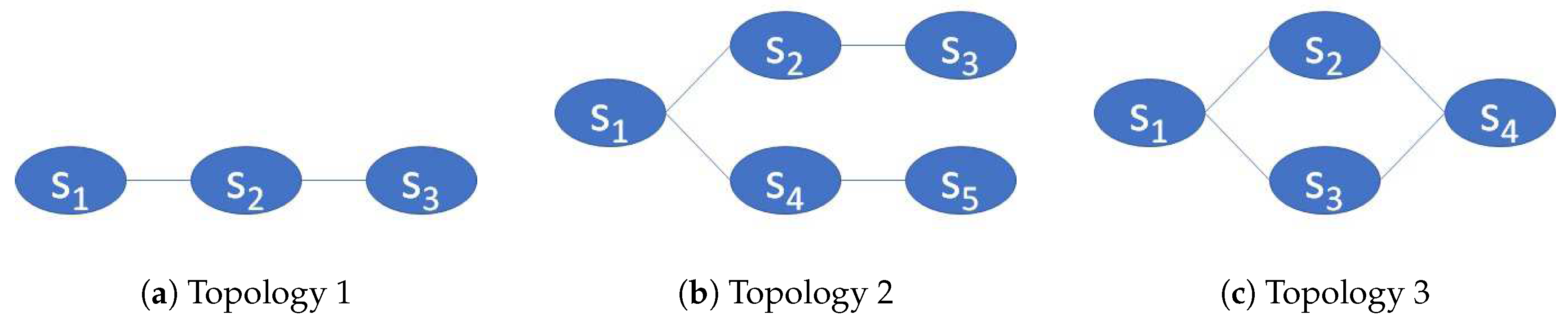
Furthermore, we assume that the SCs can have different topological characteristics following three different cases as shown in Figure 2. The first topology (Figure 2a) is the most common and simple case, where an SC is a line sequentially connecting VNFs. The second and third case is when we have bifurcated paths, where two branches are created after a VNF splits the traffic. This can happen when a reclassification occurs. As packets traverse an SC, reclassification may result in the selection of a new SC path, referred as branching. The new branch can later return to the original SC (Figure 2c) or not (Figure 2b). Further details and technical examples on these topological cases can be found in [2].
Finally, regarding delay, we assume that we have four different communication delays: (i) propagation delay , (ii) transmission delay , (iii) node queuing delay , and (iv) processing delay .
Propagation Delay
The propagation delay in a link , depends on the distance between the two communicating nodes. In this work, our network is comprised of the MEC and Cloud layers. Hence, a different propagation delay is considered according to the network layer in which the layer the VNFs are placed.
Transmission Delay
The transmission delay can be defined as the time needed to transfer the packets from a communicating device to the outgoing link , . The transmission delay depends on the average length of the packet and the transmission capacity allocated to the SC ; and it can be expressed as: .
Processing Delay
The processing delay includes the time needed by the VM hosting the VNF to apply a specific network operation on the arriving packets. Thus, the processing delay depends on the type of the VNF that is used and the resource footprint allocated to the VM. In this work, we assume an optimal server configuration, avoiding multiple packet copy operations between NIC, OS, and VM (e.g., by using Single Root Input/Ouput Virtualization for our I/O technology), providing a meticulous Non-Uniform Memory Access (NUMA) socket design, and an efficient CPU memory access [46] that can minimize the effect of those in the overall processing delay. Thus, we assume that we can fully use the total processing capacity of the server.
Queuing Delay
The last delay contributor is the queuing delay and is the time the packets spend in a node of the network as they traverse the SC path. Taking into consideration that, in this particular work, the users are randomly associated with an SC according to a Poisson point process, while the lifetime of each user is exponentially distributed, we model the communicating devices as M/M/1 queues, which have been argued as appropriate to be used for server queues [4]. Hence, the average time a packet spends in a queue can be expressed as , where is the arrival rate and is the service time of the packets [47].
Furthermore, there are extra delays for creating, booting up, and loading VNFs. However, since this is an extra level of latency that cannot be avoided, we do not consider this in our total delay evaluation.
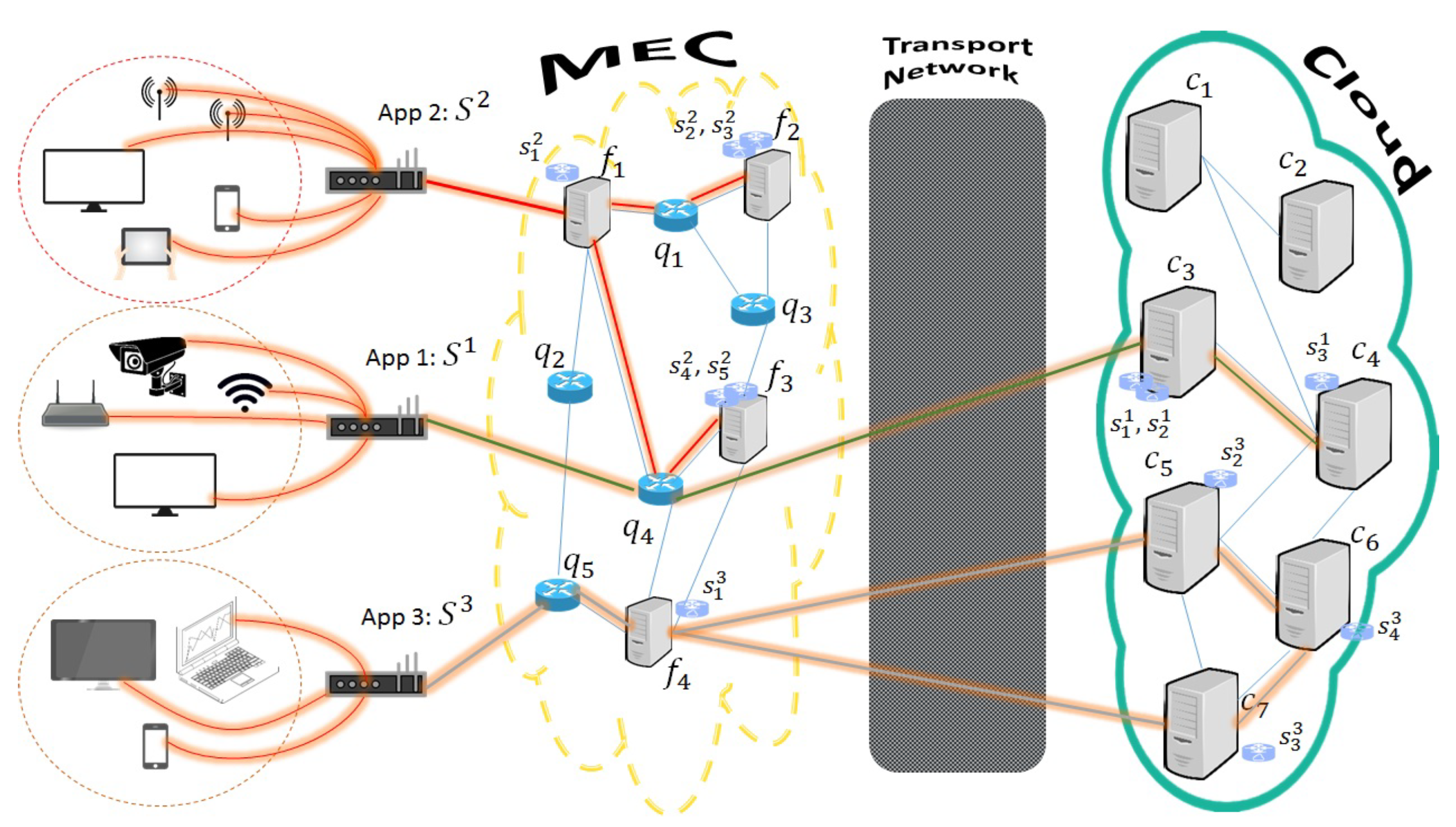
An example of the VNF-PEC placement is illustrated in Figure 3. In this example, we have three SCs () that represent the networking services that should be applied in three different applications and have the topological characteristics of Figure 2. The first SC consists of three sequentially interconnected VNFs (Figure 2a) that are allocated only in the Cloud infrastructure (e.g., due to location constraints, or due to limited resources in the MEC). Specifically, VNFs and are allocated on the Cloud site , while the third VNF is placed on the Cloud site . For the interconnection of the two first VNFs, we don’t need to find any path since they are both provisioned on the same Cloud server. On the other hand, the link between the VNFs () is allocated on the path . For the second SC, we only utilize the MEC resources (e.g., for lower latency and deployment cost) in this case the bifurcated SC (Figure 2b) is allocated as follows: VNF is allocated on the MEC device , VNFs () on MEC device , while VNFs () on MEC device . In this case, the flow of the second application is splitted in the first VNF and follows two branches. The first branch follows the {} path, and the second branch the {} path. For the last SC (Figure 2c), we utilize both MEC and Cloud resources (e.g., for traffic offloading). In particular, VNF is placed on MEC device , on Cloud site , on Cloud site , and on Cloud site . Regarding the paths that are used to interconnect the VNFs, for the first two VNFs (), the path is allocated on a set of routers that belong to the transport network, while the rest of the VNFs are placed on the Cloud and they are using inter-cloud links for the interconnection (e.g., {} and {}). There may be many placement solutions, but, in this example, we are just showing three different possible placement solutions to shed light on how the MEC and Cloud infrastructures can be utilized to facilitate the VNF placement. In the following, we explain how the appropriate available resources should be selected to optimally place the VNFs.
4. Algorithm Design
During the allocation of an SC, our goal is threefold. First of all, we need to minimize the overall deployment cost as defined in Secion Section 2 by minimizing the number of used resources both in MEC and Cloud infrastructures. Secondly, we need to minimize the communication delay expressed by the four terms presented in Section 3. Finally, we are trying to achieve the necessary load balancing by appropriately offloading the traffic between the two infrastructures. Two algorithms are proposed: (i) a Mixed Integer Programming (MIP) formulation solved using a CPLEX Branch-and-Cut search algorithm [48] and (ii) a Tabu Search Algorithm.
4.1. Mixed Integer Programming (MIP) Formulation
In order to jointly minimize all the set of requirements (e.g., deployment cost, delay, resource utilization, etc.), we introduce a Mixed Integer Programming (MIP) formulation. Two variables are defined:
: a binary variable set to 1 if the VNF is allocated on the server .
: the amount of traffic that flows between the VNFs that is routed over the link .
Objective:
The goal of the Objective 1 is as follows:
- Regarding the first two terms, it tries to minimize the number of computational and communication resources for placing the SC. This way, the overall deployment cost will be minimized.
- The weights and are included to guarantee load balancing among the available resources and are set equal to the inverse values of the available capacity of the servers n and links . To this end, we will avoid selecting only MEC resources that will lead to lower costs and appropriately offload traffic to the Cloud.
- For the third and fourth term, it tries to minimize the total delay experienced in the SC paths by selecting VNFs with minimum queuing and processing delays and links with minimum transmission and propagation delays.
The objective function is minimized subject to the following constraints. First of all, we need to ensure that the MEC and Cloud resources will not be oversubscribed (Equations (2) and (3)):
The next constraint respects flow conservation conditions, where the sources and sinks of the flows are considered, the servers that host consecutive VNFs (Equation (4)). We need to mention that the particular constraint allows path splitting towards providing a more efficient load balancing approach:
4.2. Tabu Search Algorithm
Even though MIP formulations can provide the optimal solution, they are characterized by an increased complexity that can lead to computational intractability, especially for large scale experimentation. To this end, we adopt the Tabu Search (TS) algorithm to model the VNF-PEC problem. TS is a meta-heuristic approach that applies local search to provide solutions very close to optimality [49]. In contrast with other heuristics and meta-heuristics, TS can avoid being trapped in a local optimum by incorporating a short-term memory, called Tabu List. In general, the TS algorithm is comprised of five components: (i) the Initial Solution; (ii) the Neighbor Solution; (iii) the Tabu List; (iv) the Aspiration Criterion; and (v) the Termination Criterion. These components are appropriately adapted for our problem and are described in detailed as follows, while the pseudocode for our TS implementation is provided in Algorithm 1:
- Generate Initial Solution: The initial solution is the starting point for the TS algorithm. In this work, three different initial solutions are examined. First, a random initial solution is applied. For each VNF in the SC , a random server is selected. In the second solution, we sort the available Edge and Cloud servers according to their capacity. Finally, in the third solution, we select the server with the highest capacity. If we cannot place the whole SC, we place the rest of the VNFs to neighboring servers, with the goal to jointly place the VNFs of the SC and interconnect them to minimize the propagation delay. In all cases, the selected server needs to satisfy both the resource capacity requirements and location constraints. For the interconnection of VNFs possibly residing on different servers, a shortest path algorithm is used. In the following, we set this initial solution as our best solution and current solution (lines 1–2 of Algorithm 1).
- Neighborhood Solution: This component actually defines the movement from a current solution F to a new solution in the neighborhoood of F, (lines 5–6 of Algorithm 1). It is essentially a local search mechanism for finding local improvements of the solution. In this particular work, we define three different neighborhoods. In the first case, a neighbor solution is a simple type of movement of one random VNF of the SC to a new server , while in the second case the neighbor solution is provided by moving jointly two consecutive VNFs of an SC to a new server . In the third case, we randomly reallocate all the VNFs of the SC. It should be noted that we do not restrict to move only to feasible solutions, since it is sometimes desirable to explore all parts of the search space [49].
- Tabu List: The Tabu List J is actually a short-term memory of the local search and contains the few last transformations performed on the current solution. Before applying a local search improvement, TS algorithm checks the Tabu List in order to avoid using a solution that has been recently selected. This way: (i) it prevents the algorithm for cycling into previous explored solutions; (ii) it facilitates the algorithm to move from local optima and explore other parts of the search space. In our implementation, for every VNF , we explore the impact of the length of the tabu list in the final solution by taking into consideration the last five, ten, or fifteen movements of the VNFs on different servers (lines 10–13). If the list is full, the first element of the list is removed (e.g., the oldest value in the list) (line 12).
- Aspiration Criterion: The aspiration criterion revokes a tabu, when a tabu move does not necessarily lead to cycling or to a restriction of the search space. Thus, in our implementation, the aspiration criterion is to allow a tabu move only if the new solution provides a lower cost than the current best solution. Thus, we extend the neighborhood of a current solution to include solutions allowed by the aspiration. We denote this extended neighborhood as (line 5). It should be noted that the cost is calculated using the objective function 1 (lines 7–9).
- Termination Criterion: The TS algorithm is terminated after a maximum number of iterations is reached. The number of iterations is appropriately fine-tuned in order to find the best trade-off between solution quality and time execution. In our implementation, we explore a wide range of iterations from 200 to 2000 in order to find when the algorithm converges to a local optimal solution (line 4).
| Algorithm 1 Tabu Search Algorithm |
|
5. Experimentation Environment
To model and evaluate our approach, we used and extended a discrete event java-based simulator called simulator for controlling virtual infrastructures (CVI-SIM) [50]. The particular simulator enables the evaluation of resource allocation approaches in the existence of single or multi-provider cloud infrastructures. CVI-SIM allows for modelling the physical infrastructure along with the control and management plane for more realistic scenarios. It further supports various probabilistic distributions to model the end-user requests.
In order to model the VNF-PEC problem, we created three different infrastructures representing the cloud, edge, and transport networks. To create and interconnect these infrastructures, the JUNG library was used that facilitates the modelling of the various networks as graphs. The JUNG library generates random graphs using the erdos-renyi model, while the simulator guarantees the repeatability of the experimental set up by setting up a specific seed at the beginning of the execution.
The SCs are also modeled as graphs using the JUNG library, while they belong under the IoT layer package of the CVI-SIM. In the same package, the IoT devices are also modeled including their requirements, their association with the IoT applications, their inter-arrival time, and their lifetime distribution.
Another package of the CVI-SIM includes the VNF placement algorithms. In the above section, we have already presented the theoretical aspects of the VNF-PEC algorithms along with their mathematical formulation and pseudocode. However, in this part of the paper, we provide a more complete description of the proposed algorithms and optimization approaches, including their technical aspects and how they were executed in the CVI-SIM simulator.
Regarding MIP approaches, they are characterized by an increased complexity. In addition, for the VNF Placement problem, the MIP approach is characterized as an Non-deterministic Polynomial-time (NP)-hard problem [51]. This makes the particular solution computational intractrable for large scale experimentations and thus we can only use it as a benchmark approach or an offline solution. The main reason is that the particular algorithms, as the optimal ones, are exhaustive, meaning they are trying to go through every possible solution to extract the optimal one. Thus, appropriate solvers are needed to model and solve MIP problems.
In this work, we utilized the IBM CPLEX 12.8 package to solve the MIP formulation [48]. In particular, we used the Cplex Java API to execute the MIP algorithm in our discrete event java-based simulator. Cplex library uses a generic branch and cut approach to extract the final solution. In the particular approach, the problem is decomposed in a number of continuous subproblems in a form of a tree. At the beginning, the problem is treated as a continuous relaxation of the integer constraint. If the solution contains one or more fractional variables, CPLEX will try to find cuts to remove areas of the search space that contain fractional solutions. Then, it branches to the cut (subproblem) with the more restrictive bounds until it finds an all-integer solution.
In contrast to MIP, the TS algorithm is very simple and easy to implement by simply translating the pseudocode into a java class with a dozen lines of code. Specifically, it needs a total of operations, where is the number of iterations needed to evoke the termination criterion of the algorithm, while at each iteration we only perform four operations: (i) select a random neighbor solution, (ii) calculate the cost of the new solution, (iii) compare the new solution with the current best, and (iv) finally update the Tabu List. From these four operations, the cost calculation is only proportional to the number of VNFs K consisting of the SC.
6. Results and Discussions
In this section, a comparison of the two approaches is presented via simulation. However, it should be noted that the MIP algorithm is used as a benchmark since it is not implementable for large-scale systems (e.g., MIP needs 200 × more execution time than TS). To better illustrate the efficiency of the proposed approaches, we compare them against the Instance Consolidation (IC) [38] and Baseline [40] heuristics. The IC algorithms try to consolidate as many adjacent VNFs of an SC as possible to a single instance that can be deployed on a server with the goal to minimize the resource idleness. This can be a very cost-effective solution since it can minimize the number of physical resources used for the placement of the VNFs. In the Baseline approach, the algorithm tries first to place the VNFs at the Edge. If there are not enough resources at the Edge, then it offloads the rest of the VNFs at the Cloud. The reason we selected this algorithm is to compare our approach with an algorithm that tries to benefit as much as possible from the presence of the Edge infrastructure.
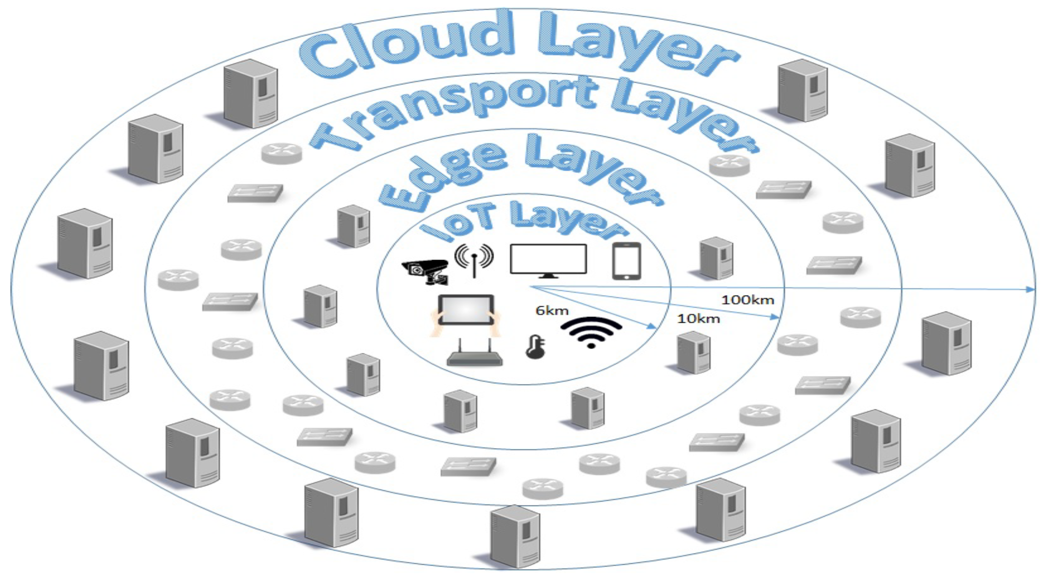
Our physical infrastructure consists of 50 nodes, with 60% cloud servers, 20% MEC servers, and 20% routers used only for forwarding purposes (e.g., for our transport network). Nodes are interconnected with 50% probability. The resource characteristics of the physical resources are provided in Table 1. Regarding the propagation delay, we assume we cover IoT applications on a smart city with a radius of 6 km. The edge servers are uniformly distributed in the vicinity of the IoT service area in a radius of 10 km. Finally, the core network lies in an area of 100 km away from our IoT devices. The infrastructure topology used to extract the propagation delay characteristics is illustrated in Figure 4.
There are 10 SCs available consisting of a number of VNFs uniformly distributed in the range from 2 to 5 following the topological characteristics as in Figure 2. The resource demands are provided in Table 1. The demands of CPU and Memory are per VNF, while the demands of bandwidth are per IoT device. Regarding the requested bandwidth, we are using typical rate values generated per IoT device according to the IoT application it belongs (e.g., Virtual Reality [52], Retail [53], e-Health [54], Wearables [55], and Autonomous Vehicles [56]). To better illustrate the importance of an efficient resource allocation, we utilize high traffic rate IoT applications in order to stress the capabilities of our infrastructure.
Each SC is assumed to handle a random number of devices according to the type of the service being processed. To this end, each SC is modeled with a different arrival rate between the range of 2–10 devices per hour, while the lifetime lies in the range of 1–24 h. The experiments last for a period of one day, while measurements are taken every half an hour. Based on this distribution, we can model a M/M/1 queue as described in Section 3. Furthermore, to model the transmission and processing delays, we assume that a server that is not fully loaded can process packets with a rate of 0.88 Mpps using packets of 1518 bytes. Moreover, we consider that each VNF may cause the traffic to be compressed, decompressed, or remain intact with an equal probability. For compression and decompression, a 20% change in the traffic is applied. Finally, we assume that 20% of the VNFs of an SC need to be deployed on the MEC layer, 30% on the Cloud, and the remaining 50% does not pose any location restrictions.
To quantify the achieved performance, two experiments are carried out. In the first experiment, we evaluate the impact of each component of the TS algorithm in the allocation solution and we extract the optimal configuration. Following that, in the second experiment, we evaluate the various allocation algorithms in terms of the deployment cost. For modeling the deployment cost, we use the pricing model provided in [57]. Furthermore, we evaluate the number of resources used by each algorithm both in terms of the number of servers and links to interconnect them and the number of SCs instantiated. Finally, the algorithms are compared in terms of the overall delay.
6.1. Experiment 1: Tabu Search Evaluation
In this experiment, we try to find the optimal configuration of the TS algorithm to provide solutions with low deployment cost. The default configuration of the TS components are set as follows: (i) random initial solution, (ii) neighborhood of one VNF, (iii) tabu list size of 10, and (iv) 1000 iterations as our termination criterion. In the following experiments, we use this default configuration and we only change the component under consideration.
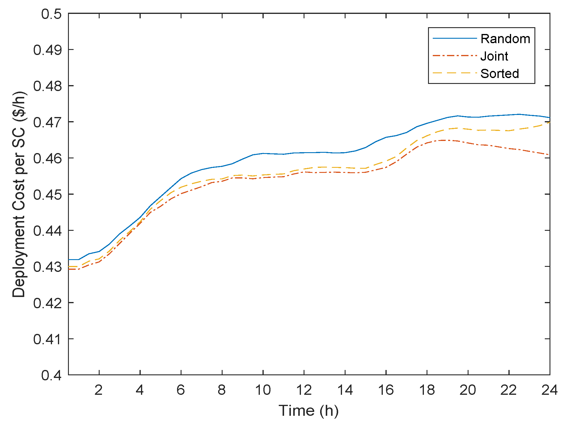
Figure 5 illustrates that the initial solution can impact the overall deployment cost. Specifically, the more sophisticated the initial solution, the better the results. For example, the Random initial solution provides the worst deployment cost, while the Joint approach (placing VNFs in neighboring servers and interconnect the VNFs) presents the best. By selecting the servers with the highest availability (Sorted), we can get a solution in between these two extremes. This reveals that providing as input to the local search mechanism an initial solution with a lower cost can help the TS algorithm to converge to a better overall solution. It is worth noting that, even though the Joint solution is the most computational intense approach, the execution-time overhead is relatively small since it is executed only once at the beginning of the algorithm.
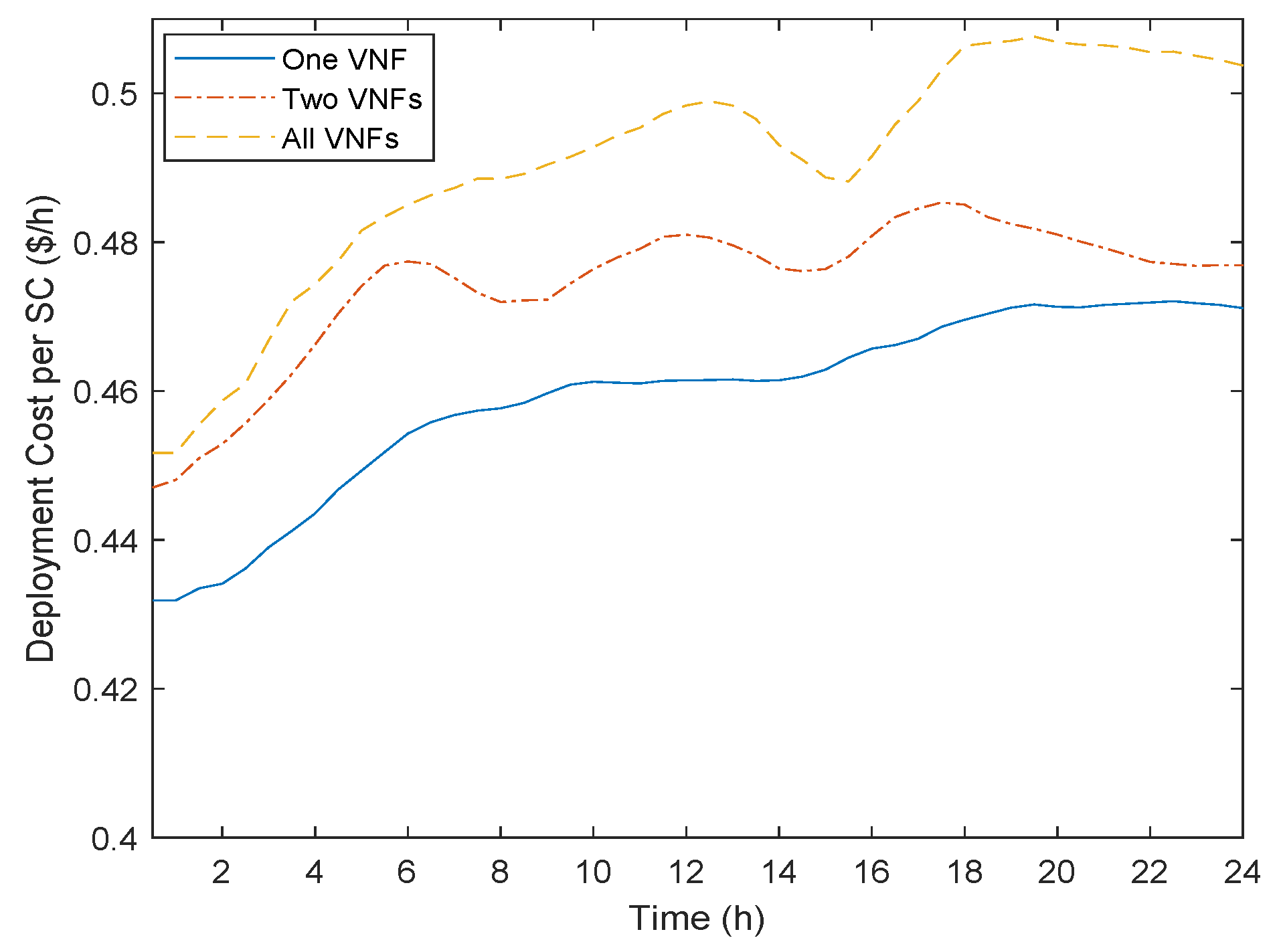
Regarding the neighborhood, as illustrated in Figure 6, for movements of one VNF at each iteration of the Local Search, we can have better results. As the neighborhood grows (for example, more VNFs), the results get worse. The reason is that moving only one VNF to a new server can help the TS algorithm to escape from local optima easier. In contrast, moving two VNFs or the whole SC at each iteration does not help the algorithm avoid a local optima, since we cannot efficiently explore the search space of available solutions. In order to perform a detailed exploration of the search space, a higher number of iterations would be needed, which would significantly increase the execution time. To this end, as our goal is to propose an algorithm that can reduce the execution time in comparison to MIP, we adopt the “One VNF” neighborhood approach.
As a third step of the fine tuning of the TS algorithm, we evaluate the impact of the Tabu List size. Figure 7 shows that, with a Tabu List of size 10, we can achieve the highest cost reduction. For a small sized Tabu List, we do not efficiently restrict the TS to not cycle into previously explored solutions, which can affect the overall deployment cost. On the other hand, if we utilize a large sized Tabu List, we significantly eliminate the search space and the available neighborhood of each VNF. For example, if a neighbor solution of a current solution is the optimal one but we select a different one from the available neighborhood, then we eliminate the algorithm to not find it for at least 15 iterations.
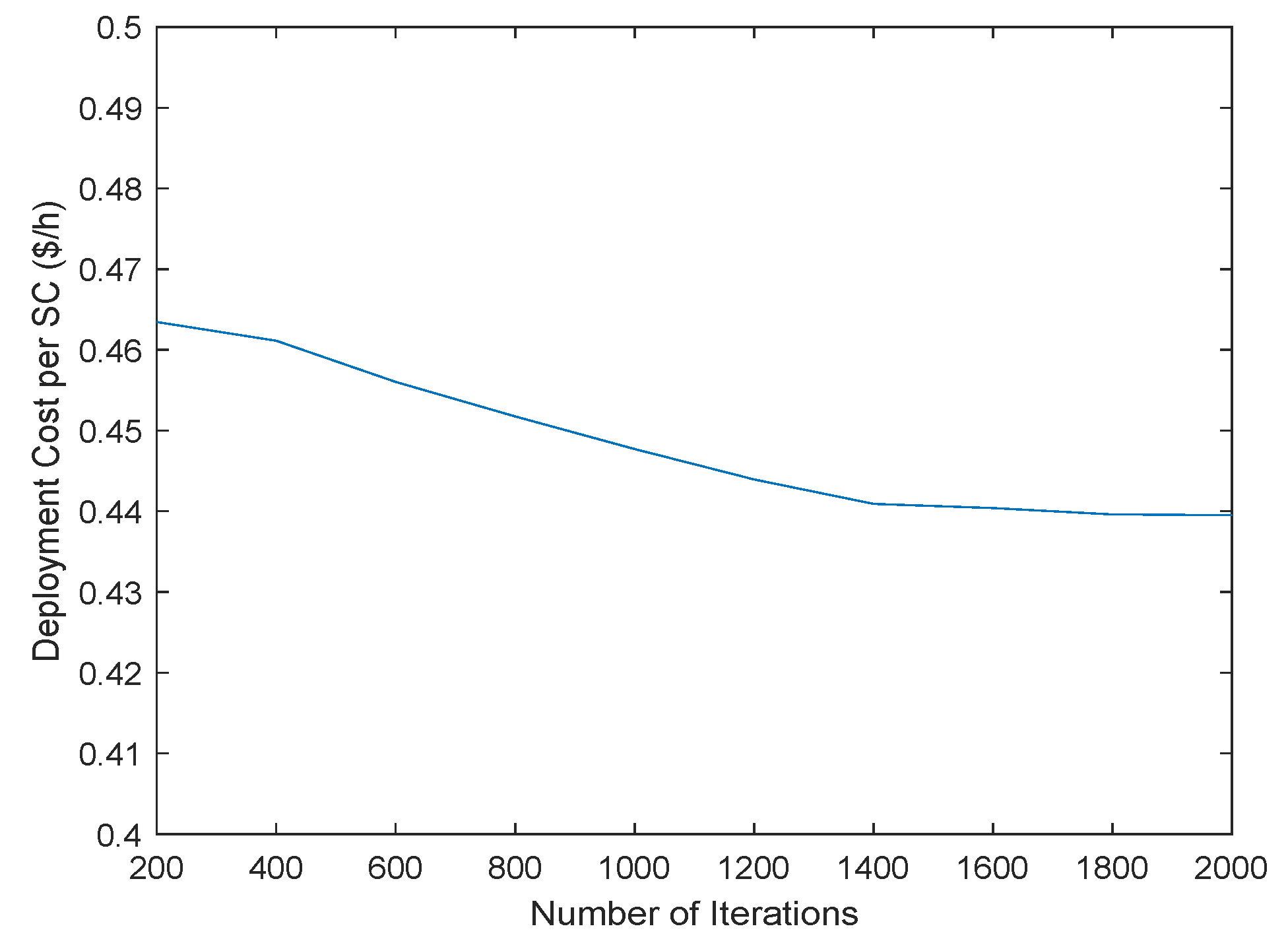
As a final performance tuning step, we evaluate the impact of the termination criterion to the overall solution. We evaluate how the cost evolves as we increase the total number of iterations from 200 to 2000 with a step of 200. As Figure 8 illustrates, as we increase the number of iterations, a more refined final solution can be extracted. However, after 1400 iterations, the algorithm converges to a local optimum and no further improvements can be achieved. To this end, in the following experiment, we configure the TS algorithm to use a Joint initial solution, with a single movement of a VNF as the neighbor solution, a Tabu List with size 10, and 1400 iterations for our termination criterion.
6.2. Experiment 2: VNF-PEC Evalution
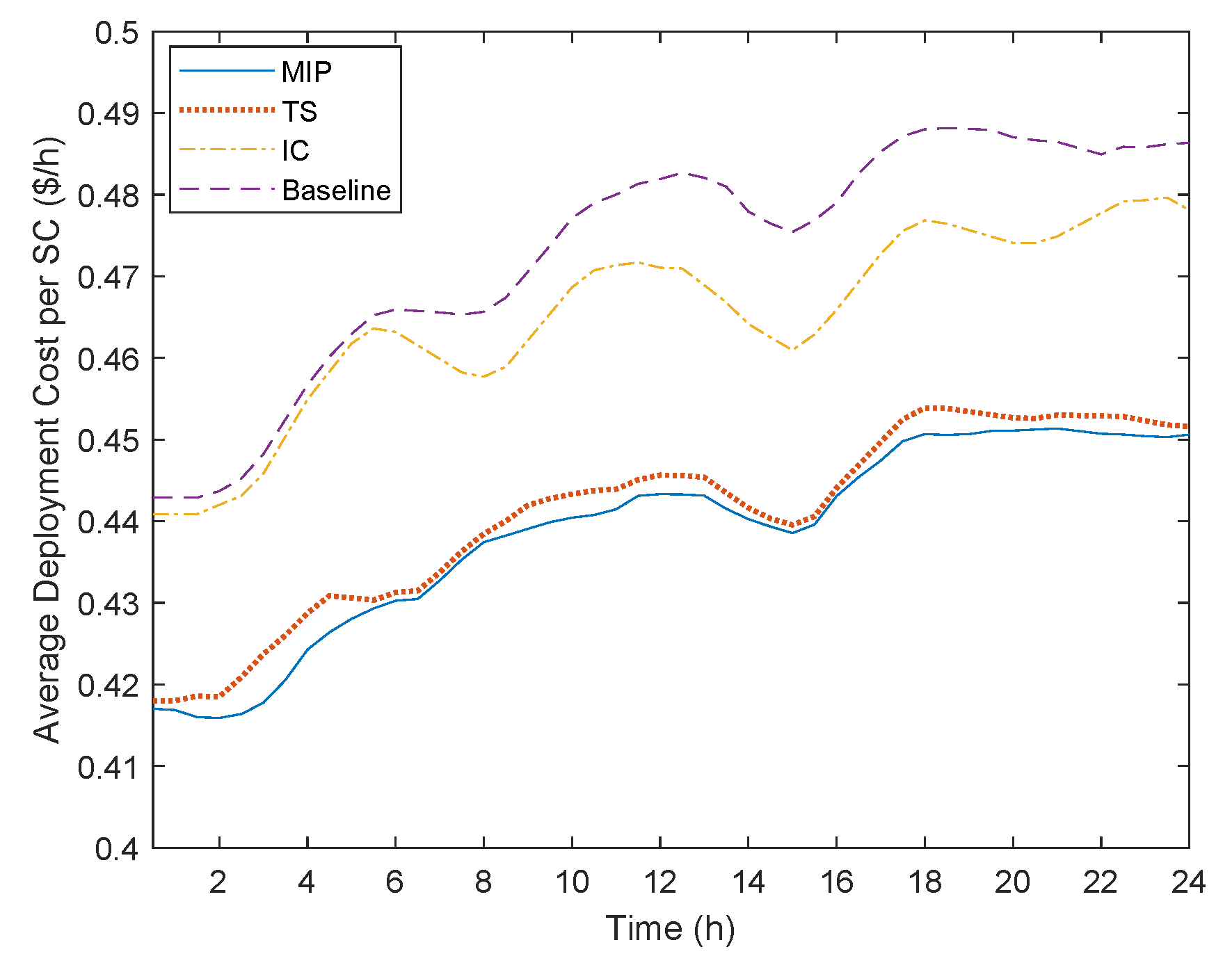
In this experiment, we evaluate the performance of the four algorithms under consideration. Figure 9 illustrates the average deployment cost per SC. As was expected, the MIP algorithm provides the lowest cost. Nonetheless, the TS approach manages to provide a very cost-efficient solution close to an optimal one. The reason is that TS adopts the same multi-objective function as the MIP algorithm. Hence, only solutions that lead to lower costs are produced at each step of the local search mechanism. On the other hand, the IC and Baseline algorithms present the worst performance. Even though both algorithms try to consolidate the VNFs on the same server or at the Edge, they fail to do it as efficiently as the other two algorithms. The rationale behind this behavior is that both algorithms do not consider any possible location constraint. Hence, they may not find neighbor servers that can host the rest of an SC, leading to using a higher number of links and thus a higher cost. This can be more evident for the Baseline algorithm, where VNFs constrained to be located at the cloud can lead to multiple crossings of the transport network, which significantly adds to the overall cost.
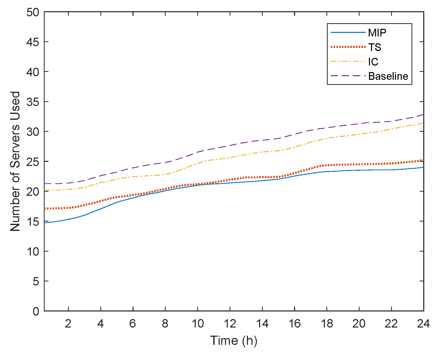
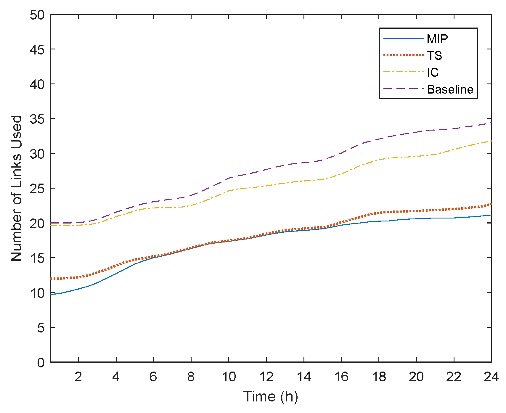
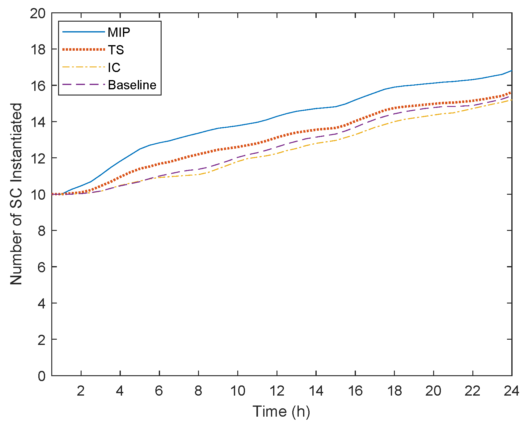
To better understand the deployment solutions produced, we also evaluate the total number of servers and links used as illustrated in Figure 10 and Figure 11. Our first observation is that, in the course of time, the number of nodes and links needed to facilitate the incoming users increases for all algorithms. This happens because even though we may consider 10 SCs, which is a typical number of a service portfolio by a SP, some of them need to be duplicated to serve all the incoming users. This can be validated by Figure 12, where we can see that initially only 10 SCs are deployed. However, as more users are associated with the SCs, more instances of the SCs are provisioned to serve the total traffic generated.
The second observation is that the IC and Baseline algorithms utilize the highest number of resources, which also validates the highest cost noticed in Figure 9. On the one hand, IC tries to consolidate as many adjacent VNFs as possible in one server. However, if two or more consecutive VNFs are constrained to be located at the Edge or Cloud, efficient consolidation is not possible, leading to higher resource utilization. Similarly, for the Baseline algorithm, if the Edge resources are stressed or if there are VNFs with Cloud resource requirements, the resource allocation performance is significantly deteriorated. On the other hand, the MIP and TS algorithms utilize less physical resources and more efficiently. This validates the efficiency of a multi-objective approach, when considering both the Edge and Cloud infrastructures. The MIP algorithm as an optimal solution provides the lowest number of resources, while TS through the refinement mechanism applied by the Local Search can minimize the performance gap.
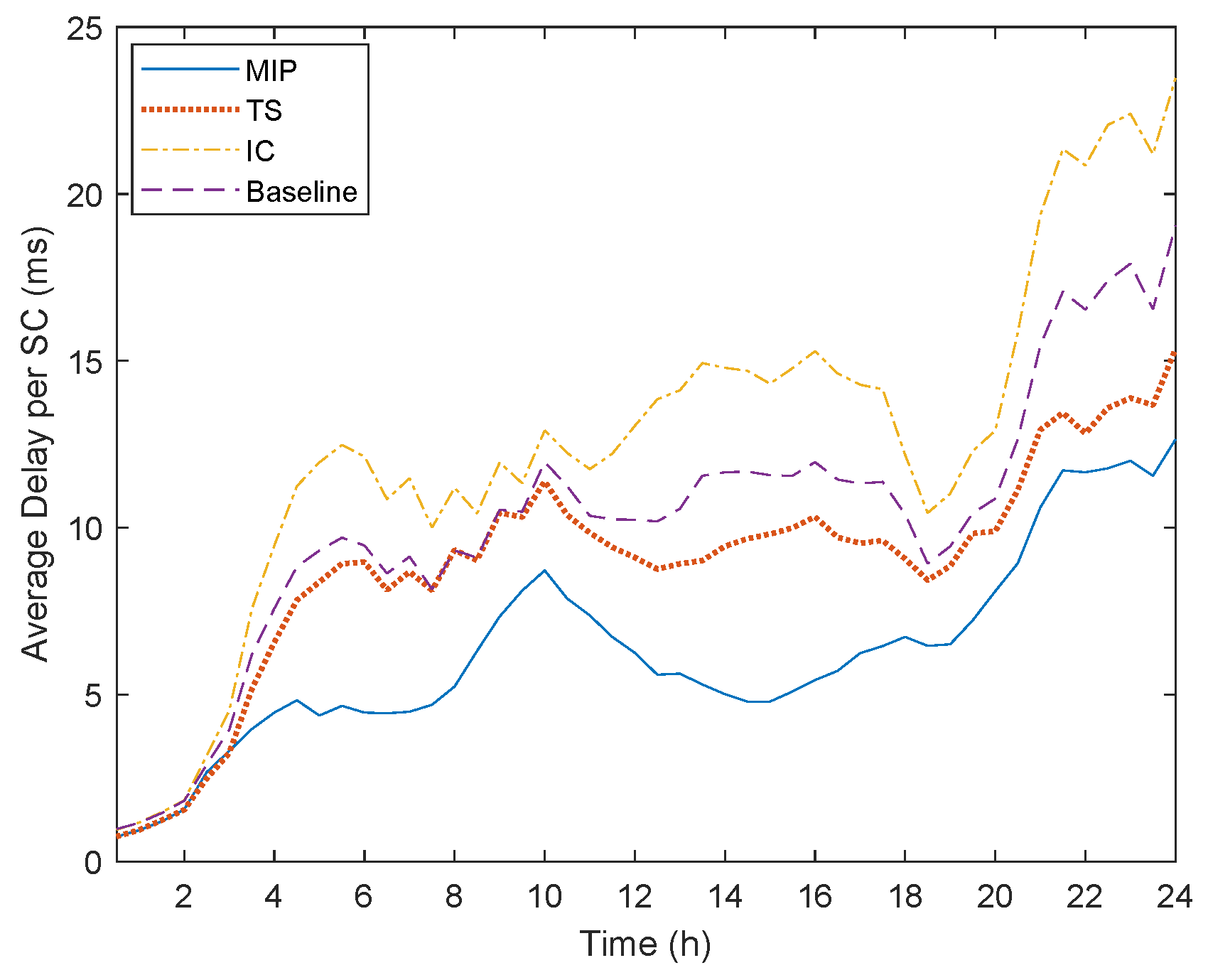
Even though we would expect that the MIP and TS algorithms would present a higher total delay, since they utilize less resources than the other two algorithms, this is not the case. As illustrated in Figure 13, the MIP algorithm manages to succeed the least total delay per SC. This is because the MIP algorithm instantiates a higher number of SC and thus distributes more efficiently the load between the servers, while minimizing processing and queuing delays. At the same time, since it jointly tries to allocate the VNFs and interconnect them with the goal to minimize the deployment cost and overall delay, it performs a much more efficient link selection. On the other hand, the TS algorithm utilizes a simple shortest path algorithm similar to the other heuristics. Nevertheless, TS presents a lower delay since it takes into consideration the location constraints and thus can avoid long paths between the Edge and Cloud. The two heuristics once again show a poor performance. The Baseline algorithm, exactly due to the fact that does not take into consideration the latency overhead of using the transport network, presents a high propagation delay that significantly contributes to the overall delay. Similarly, IC even as tries to minimize the propagation delay (e.g., through consolidating the VNFs in one server), does not take into account how overloading the servers can exponentially increase the overall queuing and processing delay. Finally, it is worth noting that the high fluctuations observed in Figure 13 are due to the dynamic traffic model that is followed.
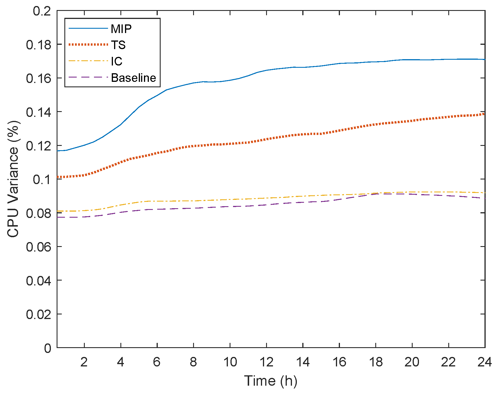
The above results demonstrate that the MIP and TS algorithms can actually reconcile the conflicting goals of reduced deployment cost and delay. In contrast, the IC and Baseline approaches, even though they consider the interoperation of Cloud and Edge layers, only consider the efficient resource utilization in terms of resource usage. This is validated by the average CPU variance among the servers utilized by their solution (Figure 14). This particular behavior, along with the other results, reveal that the two algorithms try to deplete the resources of each server before activating a new server in order to minimize resource idleness. Even though that behavior would be desirable in an environment where we only had just the Edge or Cloud infrastructures or when they are not location constrained VNFs, this is not a realistic approach. In addition, minimizing resource idleness can greatly affect the overall delay, which can be performance-harmful when considering mission critical IoT applications.
6.3. A Hybrid Simulation Approach
Above, we evaluated the performance of the proposed VNF-PEC algorithms using a java-based simulator. A simulation-based evaluation introduces many benefits, especially in terms of cost and time execution of the experiments. However, using a purely simulated environment to evaluate the performance of such a complex system, where different and heterogeneous hardware and software components are merged together towards providing a flexible and efficient end-to-end networking solution from the things to the Cloud, can lead to a discrepancy in the results extracted under an emulation approach (e.g., using IoT, Edge, and Cloud testbeds).
Even though this deviation in the results between a simulation-based and an emulation-based approach can be significant, in the particular work, we tried to create a realistic experimentation environment using real data from industrial use-cases and literature reviews to reduce the gap between these two testing methodologies. Furthermore, bearing in mind that we have to deal with mission critical IoT applications in which the delay is of utmost importance in the overall evaluation, we introduced a complete and thorough delay model to simulate the latency performance of our approaches.
On the other hand, aiming to conduct real experiments for large-scale IoT, MEC, and Cloud research concepts comes with a high setup and implementation cost. For example, in order to reproduce our experimentation set-up, we would need hundreds of IoT devices, dozens of servers, dozens of different software packages and licenses, and an extremely high amount of time for configuring our hardware and software components, making a purely emulation approach impossible.
Thus, inspired by the hybrid simulation approach proposed in [58], we design and propose a hybrid simulation alternative that can combine emulation and simulation together towards providing a more realistic evaluation.
Figure 15 illustrates the design of a hybrid simulation/emulation approach for the VNF-PEC implementation. In the particular framework, the first step is to emulate our IoT platform. For this step, we envision the utilization of an IoT testbed, where we can deploy our IoT applications and gather statistics regarding their traffic characteristics. The data statistics will be stored as traffic profiles that we will load to our traffic generator, which will be used to emulate the IoT traffic. However, since we are assuming a dynamic traffic model, we will simulate the random inter-arrival and lifetime distribution of the IoT devices, which will constitute the input of our CVI-SIM simulator. The CVI-SIM will then accordingly update the traffic profile of the traffic generator (e.g., by adjusting the number of flows corresponding to the number of IoT devices associated with the IoT applications).
The infrastructure topology including the networking aspects of representing the Edge and Cloud will be simulated as typical network graphs, upon which the VNF placement will be performed. From this placement, we will extract offline statistics of the VNF-PEC evaluation like the total deployment cost, number of leased resources and routing decisions. In other words, the CVI-SIM will act as a controller with a complete knowledge of the underlying infrastructure and the status of the available resources.
However, in this case, the intercommunication of the VNFs will be emulated by using two small-scale data centers to emulate the delay behavior of the placement solution. Specifically, as shown in Figure 15, we assume that we have an SC of five VNFs that is allocated in two servers at the Edge and another one at the Cloud. At the edge, two VNFs of the SC are allocated on the same server, while the third one at a different server. Finally, the rest two VNFs are allocated on a Cloud server. By sending the traffic and configuring the routing path, we can extract real processing and queuing delays, while the propagation delays will be simulated and added to the overall delay communication by simulating the distances between the communicating servers. In the same manner, the transport network will be simulated as a link connecting the two data centers, adding the corresponding propagation delay.
Finally, for the chaining of the VNFs, two different approaches will be used according to the placement decision. In the first case, assuming that two consecutive VNFs are allocated on the same server, a Virtual Ethernet Bridging (VEB) technique will be used by creating a bridge at the hypervisor level that will facilitate the interconnection of the VNFs. In the second case, the traffic forwarding between two VNFs residing on different servers will be performed through the switch, using a Virtual Ethernet Port Aggregator (VEPA) technique. The CVI-SIM will monitor and gather real-time metrics (e.g., delay, throughput) and will extract the necessary results after the completion of the experiment.
Nonetheless, the major challenge in this hybrid system is the response time to interconnect and synchronize the different modules. We need to make sure that the communication of the involved modules will be performed seamlessly without adding any significant delays, especially since we are measuring the response-time of mission critical IoT applications.
7. Conclusions
In this paper, we studied the problem of SC allocation for providing networking services to IoT applications, a problem called VNF Placement at the Edge and Cloud (PEC). The allocation scenario is based on a dynamic IoT multi-user model that creates dynamic traffic conditions according to the number of IoT devices associated with the IoT applications. The ultimate goal was to reconcile the conflicting requirements of reduced deployment cost and overall delay. Furthermore, in contrast with existing works, a more detailed and complete delay model is considered, while integrating additional constraints that may be encountered in a real environment, such as location constraints, SCs with different topological characteristics, and compression/decompression of the processed traffic. Two algorithms were used: (i) an optimal solution formulated as MIP problem and (ii) a Tabu Search meta-heuristic. The superior performance of the proposed solution is validated through the comparison with two algorithms proposed in the literature. The results indicate the fact that a coordinated placement of servers and links can satisfy the conflicting goals of reduced cost and delay.
Future work lies in the area of throughput performance and delay evaluation when deploying SCs both at the Edge and Cloud layers. Furthermore, we intend to assess the viability of our approach in a real-world environment and record the effects of a low-cost capacity planning solution on the overall delay. Finally, aspects of reduced reliability in the Edge will be studied and fault-tolerance models will be developed.
Author Contributions
Conceptualization, A.L. and M.I.; methodology, A.L. and I.L.; software, A.L.; validation, A.L., G.K. and I.L.; formal analysis, A.L., G.K. and I.L.; investigation, A.L., G.K.; resources, A.L., M.I.; data curation, A.L., G.K., M.I. and I.L.; writing—original draft preparation, A.L., G.K., M.I. and I.L.; visualization, A.L.
Funding
This research received no external funding.
Conflicts of Interest
The authors declare no conflict of interest.
Abbreviations
The following abbreviations are used in this manuscript:
| NFV | Network Function Virtualization |
| VNF | Virtualized Network Function |
| IoT | Internet of Things |
| MEC | Mobile Edge Computing |
| European Telecommunication Standards Institute | ETSI |
| National Institute of Standards and Technology | NIST |
| Radio Access Network | RAN |
| Service Provider | SP |
| Service Level Agreement | SLA |
| VNF-PEC | VNF Placement at the Edge and Cloud |
| VM | Virtual Machine |
| SC | Service Chain |
| QoS | Quality of Service |
| SLA | Service Level Agreement |
| SR-IOV | Single Root Input/Output Virtualization |
| NUMA | Non Uniform Memory Access |
| MIP | Mixed Integer Programming |
| TS | Tabu Search |
| NP | Non-deterministic Polynomial-time |
| IC | Instance Consolidation |
References
- Otokura, M.; Leibnitz, K.; Koizumi, Y.; Kominami, D.; Shimokawa, T.; Murata, M. Application of Evolutionary Mechanism to Dynamic Virtual Network Function Placement. In Proceedings of the IEEE International Conference on Network Protocols (ICNP), Workshops on Control, Operation and Application in SDN Protocols (CoolSDN), Singapore, 9–11 November 2016; pp. 1–6. [Google Scholar] [CrossRef]
- Halpern, J.; Pignataro, C. Service Function Chaining (SFC) Architecture; RFC: 7665; Internet Engineering Task Force (IETF): Fremont, CA, USA, 2015; Available online: https://tools.ietf.org/html/rfc7665 (accessed on 8 March 2019).
- Taleb, T.; Samdanis, K.; Mada, B.; Flinck, H.; Dutta, S.; Sabella, D. On Multi-Access Edge Computing: A Survey of the Emerging 5G Network Edge Cloud Architecture and Orchestration. IEEE Comm. Surv. Tutor. 2017, 19, 1657–1681. [Google Scholar] [CrossRef]
- Bhamare, D.; Samaka, M.; Erbad, A.; Jain, R.; Gupta, L.; Chan, H.A. Optimal Virtual Network Function Placement in multi-core service function chaining architecture. Elsevier J. Comput. Commun. 2017, 102, 1–16. [Google Scholar] [CrossRef]
- Bruschi, R.; Davoli, F.; Lago, P.; Lombardo, A.; Lombardo, C.; Rametta, C.; Schembra, G. An SDN/NFV Platform for Personal Cloud Services. IEEE Trans. Netw. Serv. Manag. 2017, 14, 1143–1156. [Google Scholar] [CrossRef]
- ETSI, Mobile Edge Computing (MEC). Framework and Reference Architecture. 2016. Available online: https://www.etsi.org/deliver/etsi_gs/mec/001_099/003/01.01.01_60/gs_mec003v010101p.pdf (accessed on 8 March 2019).
- OpenFog Consortium Architecture Working Group. OpenFog Reference Architecture for Fog Computing. 2017. Available online: https://www.openfogconsortium.org/wp-content/uploads/OpenFog_Reference_Architecture_2_09_17-FINAL-1.pdf (accessed on 8 March 2019).
- Iorga, M.; Feldman, L.; Barton, R.; Martin, M.J.; Goren, N.S.; Mahmoudi, C. Fog Computing Conceptual Model; Special Publication (NIST SP)—500-325; National Institute of Standards and Technology: Gaithersburg, MD, USA, 2018.
- Shi, W.; Cao, J.; Zhang, Q.; Li, Y.; Xu, L. Edge Computing: Vision and Challenges. IEEE Internet Things 2016, 3, 637–643. [Google Scholar] [CrossRef]
- Mao, Y.; You, C.; Zhang, J.; Huang, K.; Letaief, K.B. Mobile Edge Computing: Survey and Research Outlook. IEEE Internet Things 2017. Available online: https://arxiv.org/abs/1701.01090 (accessed on 8 March 2019).
- Leivadeas, A.; Falkner, M.; Lambadaris, I.; Kesidis, G. Optimal Virtualized Network Function Allocation for an SDN Enabled Cloud. Elsevier Comput. Stand. Interfaces 2017, 54, 266–278. [Google Scholar] [CrossRef]
- Chua, F.C.; Ward, J.; Zhang, Y.; Sharma, P.; Huberman, B.A. Stringer: Balancing Latency and Resource Usage in Service Function Chain Provisioning. IEEE Internet Comput. 2016, 20, 22–31. [Google Scholar] [CrossRef] [Green Version]
- Dechouniotis, D.; Leontiou, N.; Athanasopoulos, N.; Christakidis, A.; Denazis, S. A control-theoretic approach towards joint admission control and resource allocation of cloud computing services. Int. J. Netw. Manag. 2015, 25, 159–180. [Google Scholar] [CrossRef] [Green Version]
- Luizelli, M.C.; Raz, D.; Sa’ar, Y.; Yallouz, J. The actual cost of software switching for NFV chaining. In Proceedings of the IFIP/IEEE Symposium on Integrated Network and Service Management, Lisbon, Portugal, 8–12 May 2017; pp. 335–343. [Google Scholar] [CrossRef]
- Choi, T.; Kim, T.; Tavernier, W.; Korvala, A.; Pajunpaa, J. Agile Management of 5G core network based on SDN/NFV technology. In Proceedings of the IEEE International Conference on Information and Communication Technology Convergence (ICTC), Jeju Island, Korea, 18–20 October 2017; pp. 840–844. [Google Scholar] [CrossRef]
- Salman, O.; Elhajj, I.; Kayssi, A.; Chehab, A. Edge Computing Enabling the Internet of Things. In Proceedings of the IEEE World Forum on Internet of Things (WF-IoT), Milan, Italy, 14–16 December 2015; pp. 603–605. [Google Scholar] [CrossRef]
- Luizelli, M.C.; Bays, L.R.; Buriol, L.S.; Barcellos, M.P.; Gaspary, L.P. Piecing Together the NFV Provisioning Puzzle: Efficient Placement and Chaining of Virtual Network Functions. In Proceedings of the IFIP/IEEE International Symposium on Integrated Network Management, Ottawa, ON, Canada, 11–15 May 2015; pp. 98–106. [Google Scholar] [CrossRef]
- Mehraghdam, S.; Keller, M.; Karl, H. Specifying and Placing Chains of Virtual Network Functions. In Proceedings of the IEEE 3rd International Conference on Cloud Networking (CloudNet), Luxembourg, 8–10 October 2014; pp. 7–13. [Google Scholar] [CrossRef]
- Sahhaf, S.; Tavernier, W.; Rost, M.; Schmid, S.; Colle, D.; Pickavet, M.; Demeester, P. Network Service Chaining with Optimized Network Function Embedding Supporting Service Decompositions. Elsevier Comput. Netw. 2015, 93, 492–505. [Google Scholar] [CrossRef]
- Antevski, K.; Martín-Pérez, J.; Molner, N.; Chiasserini, C.F.; Malandrino, F.; Frangoudis, P.; Ksentini, A.; Li, X.; SalvatLozano, J.; Martínez, R.; et al. Resource Orchestration of 5G transport networks for vertical industries. In Proceedings of the 2018 IEEE 29th Annual International Symposium on Personal, Indoor and Mobile Radio Communications (PIMRC), Montreal, QC, Canada, 9–12 September 2018. [Google Scholar]
- Benkacem, I.; Taleb, T.; Bagaa, M.; Flinck, H. Optimal VNFs placement in CDN Slicing over Multi-Cloud Environment. IEEE J. Sel. Areas Commun. 2018, 36, 616–627. [Google Scholar] [CrossRef]
- Chiaraviglio, L.; D’Andreagiovanni, F.; Siderotti, G.; Melazzi, N.B.; Salsano, S. Optimal Design of 5G Superfluid Networks: Problem Formulation and Solutions. In Proceedings of the IFIP/IEEE International Conference on Innovation in Clouds, Internet and Networks (ICIN), Paris, France, 20–22 February 2018; pp. 1–8. [Google Scholar] [CrossRef]
- Pham, C.; Tran, N.H.; Ren, S.; Saad, W.; Hong, C.S. Traffic-aware and Energy-efficient VNF Placement for Service Chaining: Joint Sampling and Matching Approach. IEEE Trans. Serv. Comput. 2018, 99, 1. [Google Scholar] [CrossRef]
- Wen, T.; Yu, H.; Sun, G.; Liu, L. Network Function Consolidation in Service Function Chaining Orchestration. In Proceedings of the IEEE International Conference on Communications (ICC), Kuala Lumpur, Malaysia, 23–27 May 2016; pp. 1–6. [Google Scholar] [CrossRef]
- Leivadeas, A.; Falkner, M.; Lambadaris, I.; Kesidis, G. Resource Management and Orchestration for a Dynamic Service Chain Steering Model. In Proceedings of the IEEE Conference on Global Communications (GLOBECOM), Washington, DC, USA, 4–8 December 2016; pp. 1–6. [Google Scholar] [CrossRef]
- Feng, H.; Llorca, J.; Tulino, A.M.; Molisch, A. Dynamic Network Service Optimization in Distributed Cloud Networks. In Proceedings of the IEEE International Conference on Computer Communications (INFOCOM), Workshops on Software-Driven Flexible and Agile Networking, San Francisco, CA, USA, 10–15 April 2016; pp. 300–305. [Google Scholar] [CrossRef]
- Savi, M.; Tornatore, M.; Verticale, G. Impact of Processing Costs on Service Chain Placement in Network Functions Virtualization. In Proceedings of the IEEE Conference on Network Function Virtualization and Software Defined Network (NFV-SDN), San Francisco, CA, USA, 18–21 November 2015; pp. 191–197. [Google Scholar] [CrossRef]
- Lombardo, A.; Manzalini, A.; Riccobene, V.; Schembra, G. An analytical tool for performance evaluation of software defined networking services. In Proceedings of the IEEE Network Operations and Management Symposium (NOMS), Krakow, Poland, 5–9 May 2014; pp. 1–7. [Google Scholar] [CrossRef]
- Luizelli, M.C.; Cordeiro, W.L.C.; Buriol, L.S.; Gaspary, L.P. A fix-and-optimize approach for efficient and large scale virtual network function placement and chaining. Elsevier J. Comput. Commun. 2017, 102, 67–77. [Google Scholar] [CrossRef]
- Addis, B.; Belabed, D.; Buet, M.; Secci, S. Virtual Network Functions Placement and Routing Optimization. In Proceedings of the IEEE International Conference on Cloud Networking (CloudNet), Niagara Falls, ON, Canada, 5–7 October 2015; pp. 171–177. [Google Scholar] [CrossRef]
- Leontiou, N.; Dechouniotis, D.; Denazis, S.; Papavassiliou, S. A hierarchical control framework of load balancing and resource allocation of cloud computing services. Elsevier J. Comput. Electr. Eng. 2018, 67, 235–251. [Google Scholar] [CrossRef]
- Hegyi, A.; Flinck, H.; Ketyko, I.; Kuure, P.; Nemes, C.; Pinter, L. Application Orchestration in Mobile Edge Cloud: Placing of IoT Applications to the Edge. In Proceedings of the IEEE International Workshops on Foundations and Applications of Self* Systems, Augsburg, Germany, 12–16 September 2016; pp. 230–235. [Google Scholar] [CrossRef]
- Leivadeas, A.; Falkner, M.; Lambadaris, I.; Kesidis, G. Dynamic Virtualized Network Function Allocation in a Multi-Cloud Environment. In Proceedings of the IEEE International Conference on Telecommunications (ICT), Thessaloniki, Greece, 16–18 May 2016; pp. 1–5. [Google Scholar] [CrossRef]
- Nam, Y.; Song, S.; Chung, J.M. Clustered NFV Service Chaining Optimization in Mobile Edge Clouds. IEEE Commun. Lett. 2017, 21, 350–353. [Google Scholar] [CrossRef]
- Ma, W.; Beltran, J.; Pan, Z.; Pan, D.; Pissinou, N. SDN-Based Traffic Aware Placement of NFV Middleboxes. IEEE Trans. Netw. Serv. Manag. 2017, 14, 528–542. [Google Scholar] [CrossRef]
- Zanzi, L.; Giust, F.; Sciancalepore, V. M2EC: A Multi-tenant Resource Orchestration in Multi-Access Edge Computing Systems. In Proceedings of the IEEE International Conference on Wireless Communications and Networking Conference (WCNC), Barcelona, Spain, 15–18 April 2018; pp. 1–6. [Google Scholar] [CrossRef]
- Alleg, A.; Ahmed, T.; Mosbah, M.; Riggio, R.; Boutaba, R. Delay-aware VNF placement and chaining based on a flexible resource allocation approach. In Proceedings of the IEEE International Conference on Network and Service Management (CNSM), Tokyo, Japan, 26–30 November 2017; pp. 1–7. [Google Scholar] [CrossRef]
- Wang, J.; Qi, H.; Li, K.; Zhou, X. PRSFC-IoT: A Performance and Resource Aware Orchestration System of Service Function Chaining for Internet of Things. IEEE Internet Things J. 2018, 5, 1400–1410. [Google Scholar] [CrossRef]
- Cao, J.; Zhang, Y.; An, W.; Chen, X.; Sun, J.; Han, Y. VNF-FG Design and VNF Placement for 5G Mobile Networks. Springer J. Inf. Sci. 2017, 60, 1–15. [Google Scholar] [CrossRef]
- Jemaa, F.B.; Pujolle, G.; Pariente, M. QoS-aware VNF placement Optimization in Edge-Central Carrier Cloud Architecture. In Proceedings of the IEEE International Conference on Global Communications Conference (GLOBECOM), Washington, DC, USA, 4–8 December 2016; pp. 1–7. [Google Scholar] [CrossRef]
- Carpio, F.; Dhahri, S.; Jukan, A. VNF Placement with Replication for Load balancing in NFV networks. In Proceedings of the IEEE International Conference on Communications (ICC), Paris, France, 21–25 May 2017; pp. 1–6. [Google Scholar] [CrossRef]
- Munoz, R.; Vilalta, R.; Yoshikane, N.; Casellas, R.; Martinez, R.; Tsuritani, T.; Morita, I. Integration of IoT, Transport SDN and Edge/Cloud computing for Dynamic Distribution of IoT Analytics and Efficient Use of Network Resources. IEEE J. Lightwave Technol. 2018, 36, 1420–1428. [Google Scholar] [CrossRef]
- Lingen, F.V.; Yannuzzi, M.; Jain, A.; Irons-Mclean, R.; Lluch, O.; Carrera, D.; Perez, J.L.; Gutierrez, A.; Montero, D.; Marti, J.; et al. The Unavoidable Convergence of NFV, 5G, and Fog: A Model-Driven Approach to Bridge Cloud and Edge. IEEE Commun. Mag. 2017, 55, 28–35. [Google Scholar] [CrossRef]
- Yannuzzi, M.; Lingen, F.V.; Jain, A.; Lluch, O.; Flore, M.M.; Carrera, D.; Perez, J.L.; Montero, D.; Chacin, P.; Corsaro, A.; et al. A New Era for Cities with Fog Computing. IEEE Internet Comput. 2017, 21, 54–67. [Google Scholar] [CrossRef]
- Jia, M.; Liang, W.; Xu, Z.; Huang, M. Cloudlet Load Balancing in Wireless Metropolitan Area Networks. In Proceedings of the IEEE International Conference on Communications (INFOCOM), San Francisco, CA, USA, 10–14 April 2016; pp. 1–9. [Google Scholar] [CrossRef]
- Pitaev, N.; Falkner, M.; Leivadeas, A.; Lambadaris, I. Multi-VNF Performance Characterization for Virtualized Network Functions. In Proceedings of the IEEE Conference on Network Softwarization (NetSoft), Bologna, Italy, 3–7 July 2017; pp. 1–5. [Google Scholar] [CrossRef]
- Ng, C.-H.; Boon-Hee, S. Queuing Modelling Fundamentals with Applications in Communication Networks, 2nd ed.; Wiley: Hoboken, NJ, USA, 2008; ISBN 978-0-470-51957-8. [Google Scholar]
- IBM ILOG CPLEX Optimizer. Available online: https://www.ibm.com/analytics/cplex-optimizer (accessed on 8 March 2019).
- Gendreau, M.; Potvin, J.Y. Handbook of Metaheuristics, 2nd ed.; Springer: Berlin, Germany, 2010; ISBN 978-1-4419-1665-5. [Google Scholar]
- Simulator for Controlling Virtual Infrastructures (CVI-SIM). Available online: https://github.com/arisleiv/CVI_SIM (accessed on 8 March 2019).
- Ma, W.; Medina, C.; Pan, D. Traffic-Aware Placement of NFV Middleboxes. In Proceedings of the IEEE International Conference on Global Communications (GLOBECOM), San Diego, CA, USA, 6–10 December 2015; pp. 1–6. [Google Scholar] [CrossRef]
- Chen, M.; Saad, W.; Yin, C. Virtual Reality Over Wireless Networks: Quality-of-Service Model and Learning-based Resource Management. IEEE Trans. Commun. 2018, 66, 5621–5635. [Google Scholar] [CrossRef]
- Intel. The Business Case for MEC in Retail: A TCO Analysis and its Implications in the 5G era, Intel Technical White Paper. 2017. Available online: https://builders.intel.com/docs/networkbuilders/the-business-case-for-mec-in-retail-a-tco-analysis-and-its-implications-in-the-5g-era.pdf (accessed on 8 March 2019).
- Huawei. 5G Unlocks a World of Opportunities—Top Ten 5G Use Cases. Huawei Whitepaper, 2017. Available online: http://www.huawei.com/en/industry-insights/outlook/mbb-2020/trends-insights/5g-unlocks-a-world-of-opportunities (accessed on 8 March 2019).
- Porambage, P.; Okwuibe, J.; Liyanage, M.; Ylianttila, M.; Taleb, T. Survey on Multi-Access Edge Computing for Internet of Things Realization. IEEE Commun. Surv. Tutor. 2018, 20, 2961–2991. [Google Scholar] [CrossRef]
- Krzanich, B. Data is the New Oil in the Future of Automated Driving. Intel Editorial, 2016. Available online: https://newsroom.intel.com/editorials/krzanich-the-future-of-automated-driving/ (accessed on 8 March 2019).
- Amazon EC2 Pricing. Available online: https://aws.amazon.com/ec2/pricing/ (accessed on 8 March 2019).
- Ficco, M.; Pietrantuono, R.; Russo, S. Hybrid Simulation and Test of Vessel Traffic Systems on the Cloud. IEEE Access 2018, 6, 47273–47287. [Google Scholar] [CrossRef]
Figure 1.
Cloud-based Internet of Things platform.

Figure 2.
Different service chain topologies.

Figure 3.
VNF Placement at the Edge and Cloud example.

Figure 4.
Infrastructure topology.

Figure 5.
Impact of initial solution in Tabu Search.

Figure 6.
Impact of the Neighborhood of Local Search in Tabu Search.

Figure 7.
Impact of the Tabu list size in Tabu Search.

Figure 8.
Impact of the Termination Criterion in Tabu Search.

Figure 9.
Average deployment cost per service chain.

Figure 10.
Total number of nodes used.

Figure 11.
Total number of links used.

Figure 12.
Total number of service chains instantiated.

Figure 13.
Total average delay per service chain.

Figure 14.
Average CPU variance of activated servers.

Figure 15.
Hybrid simulation/emulation approach.


Table 1.
Resource characteristics.
| Characteristic | Server | VNF Demand |
|---|---|---|
| CPU (cores) | 8 | 1, 2, 4 |
| Memory (GB) | 24 | 4, 8 |
| Bandwidth (Gbps) | 10 | 0.1, 0.2, 0.3, 0.5 |
© 2019 by the authors. Licensee MDPI, Basel, Switzerland. This article is an open access article distributed under the terms and conditions of the Creative Commons Attribution (CC BY) license (http://creativecommons.org/licenses/by/4.0/).
Share and Cite
MDPI and ACS Style
Leivadeas, A.; Kesidis, G.; Ibnkahla, M.; Lambadaris, I. VNF Placement Optimization at the Edge and Cloud †. Future Internet 2019, 11, 69. https://doi.org/10.3390/fi11030069
AMA Style
Leivadeas A, Kesidis G, Ibnkahla M, Lambadaris I. VNF Placement Optimization at the Edge and Cloud †. Future Internet. 2019; 11(3):69. https://doi.org/10.3390/fi11030069
Chicago/Turabian StyleLeivadeas, Aris, George Kesidis, Mohamed Ibnkahla, and Ioannis Lambadaris. 2019. "VNF Placement Optimization at the Edge and Cloud †" Future Internet 11, no. 3: 69. https://doi.org/10.3390/fi11030069
Note that from the first issue of 2016, this journal uses article numbers instead of page numbers. See further details here.