1. Introduction
Testing is an essential activity in software engineering. In the simplest terms, it amounts to observing the execution of a software system to validate whether it behaves as intended and to identify potential malfunctions [
1]. Software testing constitutes about 40% to 60% of the development costs [
2]. A major part of the testing effort is for specifying and running the tests, and these are usually performed manually. Model-based testing is a promising technology to reduce the testing effort and increase the test efficiency.
Automation of software development and software testing on the basis of executable models and simulation promises significant reductions in fault-removal cost and development time. Utting
et al. [
3] define model-based testing as a variant of testing that relies on explicit behavior models that encode the intended behavior of a system, and possibly the behavior of its environment. According to Bertolino [
1], the major goal of model-based testing (MBT) is automatic generation of test artifacts from models. MBT offers considerable promise in reducing the cost of test generation, increasing the effectiveness of the tests, and shortening the testing effort [
4].
The software life cycle starts with requirements capturing by the business analyst; these requirements are used by the design analyst for designing the software architecture, and later both of these are used for developing test models. Requirements specification, design models and test models can be considered the integral parts of model-based testing. Defining relationships between models could provide effective verification and analysis of the consistencies and dependencies between models. Study has to be focused to bridge the gap by defining strong relationships between these models.
In this paper, we present an approach for defining relationships between the major constituents of model-based testing. We discuss how these models can be defined and how to define the relationships between these models, thus filling the gap between different phases of the software life cycle. This paper is organized into an overview of the need for traceability between requirements model, design model, and test model, related work, and the new approach.
2. The Need for Traceability in Model-Based Testing
The Institute of Electrical and Electronics Engineers (IEEE) defines traceability as the degree to which relationships can be established between two or more products of the development process, especially products having a predecessor–successor or master-subordinate relationship to one another [
5]. Typically, traceability relations denote satisfiability, dependency, evolution, and rationalization relations between software artifacts [
6]. Gotel and Finkelstein in [
7] define traceability as the ability to describe and follow the life of a requirement in both a forwards and backwards direction. Murray
et al. refer to traceability as the ability to identify requirements at different levels of abstraction and to show that they have been implemented and tested [
8].
The above definitions do not cover all aspects of traceability, and most of them focus on requirements traceability. Since design models and test models also play a major role in model-based testing, there is a need for defining the design model and test model relationship as well. The automation of bidirectional traceability between requirements and test cases is a key aspect of MBT [
9]. Bidirectional traceability is the ability to trace links between two parts of the software development process with respect to each other [
9]. Dalal
et al. [
4] suggest that defects of a model can be minimized by ensuring the traceability from requirements to the part of models.
Traceability is widely used in the software development life cycle and is an active research area in software engineering [
10]. Since tests are derived from models, the correctness of model and the consistency of requirements are important. Therefore, there is a need to understand the following:
What are the requirements?
How to derive system design from the requirements model?
How to derive tests from system design and the requirements model?
How are they related?
What is the impact on other models, when any of the models is changed?
Traceability between these models will help to understand the above questions. Traceability in model-based testing helps to:
Trace back to the respective requirements and design models when a test fails.
Identify the problems in the design model and the inconsistencies in the requirements elicitation and tests.
Fills the gap between business analyst, system designer, and test developer.
Specify the evolution of design model from requirements.
Show the evolution of test models from requirements and design model.
3. Related Work
Traceability is a popular and an active research topic in software engineering [
10]. Researchers have proposed different ways for traceability, including information retrieval based on the similarity between texts present in different software artifacts [
11]. Another approach is using the hypertext technology. Here, traceability is achieved by maintaining hypertext links between different software artifacts [
12]. Annotations with identifier tags are another traceability technique. During the modeling phase, models are annotated with requirement identifier tags [
13].
Traceability is also used in model-based testing tools. In MATERA [
14], the requirements can be linked to different parts of the UML-based (Unified Modeling Language) system specification, for instance, to models or to model elements, to ensure requirements traceability throughout the process. In MATERA, models are annotated with OCL. Bouquet
et al. [
13] propose an approach based on annotating the model with requirements for traceability. The Leirios tool (Smarttesting) [
15] is then used for generating tests and test cases, and a traceability matrix is obtained after the test is executed.
All the above proposed approaches use requirements traceability. Since system models and test models are also the major constituents, system model traceability and test model traceability is as important as the requirements traceability. Our approach proposes a traceability technique that covers requirements model, design model, and test model.
4. Proposed Approach
Drawing upon the key motivation factors identified in
Section 2 and
Section 3, in this section we describe the proposed approaches for bridging the gap between the requirements model, design model, and the test model.
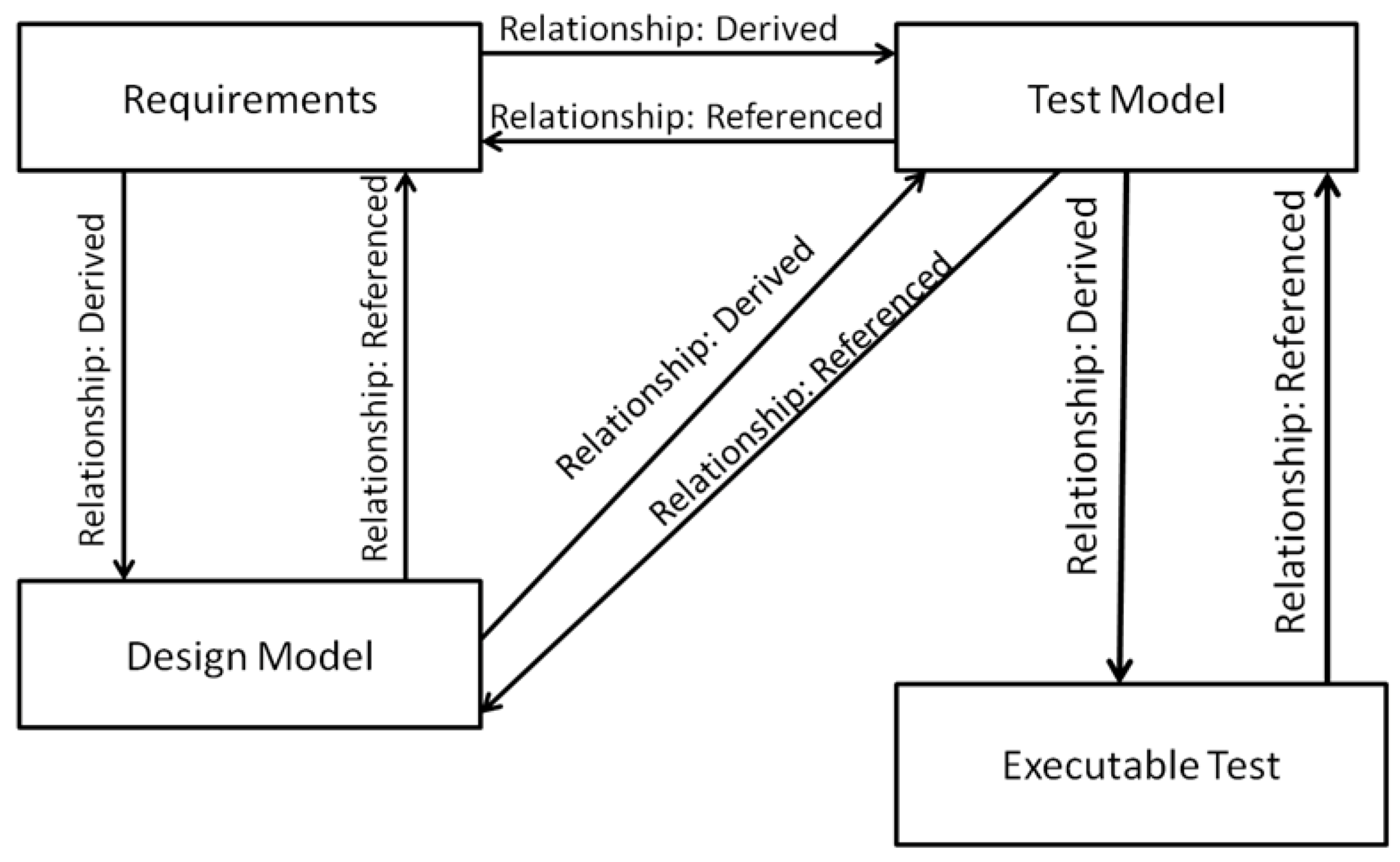
Figure 1 provides an overview of the relationship between the different models.
Figure 1.
Overview of relationships.
Figure 1.
Overview of relationships.
Our approach starts from analyzing the informal requirements formulated in any natural language. Natural language requirements will be formulated and structured into different use case scenarios based on predefined templates. Usage scenarios will be used for creating design models. Design models will be developed using appropriate UML diagrams. Each element in the use case scenario will be connected to the corresponding design model items. From the use case model and design model, the test model will be created. UML diagrams will be used for creating the test models. Executable tests will be generated from the test model. Relationships between use case model (requirements model), corresponding design model, test model and executable tests will be defined using our approach. The main focus of this paper will be confined only in bridging the gap between these models by providing efficient traceability; test generation from the test model is not in the scope of this paper. Therefore, the approach will be completed by defining relationships between these models.
4.1. Defining Relationships between Models
Relationships between two models can be classified as “derived” and “referenced.”
4.1.1. Derived Relationship
By this relationship, the evolution of models and model elements from one phase to another is represented. The design model is derived from the requirements model, so the evolution of the design model and its model parts from requirements model and its model parts is defined as a derived relationship. Each part in the design model will have a derived relationship with the requirements model. Similarly, test models derived from the requirements model and design model have a derived relationship to the requirements model and design model. The relationship that shows the evolution of a model or model parts from another model or a model part is referred to as a derived relationship.
4.1.2. Referenced Relationship
This relationship defines the backward relationship to the source elements. The relationship from the design model to the requirements model is a referenced relationship.
4.2. Relation Definition Markup Language
In our approach, the relationship from one model to another is defined by exploiting XML technologies. The relationship is formalized through a formal XML structure called RDML, whose syntax is defined using the XML schema. RDML stands for relation definition markup language based on an XML schema that comprises specific elements to define the relationship between models [
16]. For each model, an “RDML” definition will be available that defines the relationship with other models, the type of relationship, the relationship of each model part,
etc. We propose the RDML structure in order to express the derived and referenced relationship between the different models in a formal manner.
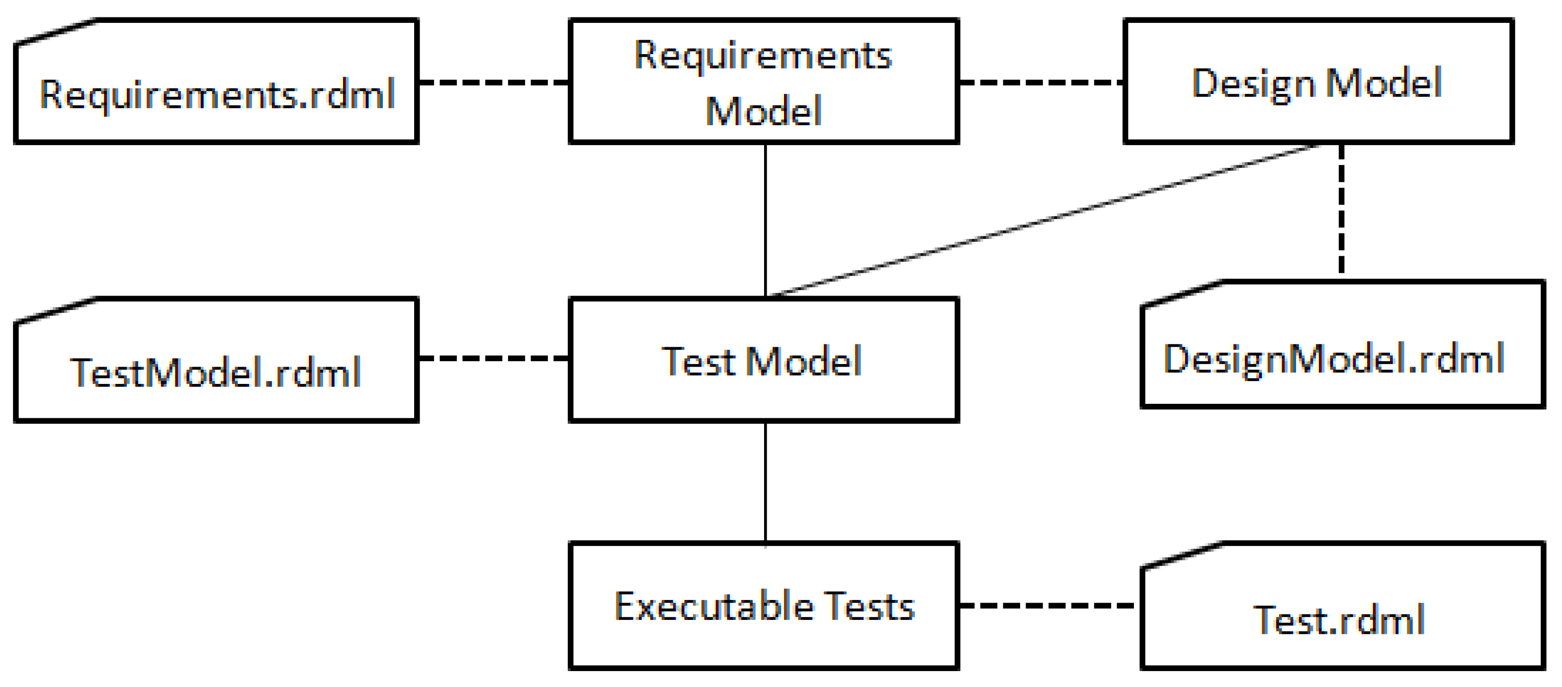
Each model will have a separate RDML file (
Figure 2), based on an XML schema. Each RDML file will have an entry for the model, for instance, <Scenario>, <DesignModel>, <TestScenario>. Relationship is represented by the element <Relationship> that will contain the <DerivedRelationship> and <ReferencedRelationship> elements. <DerivedRelationship> element will have two subelements referring to the derived models. For example, the requirements.RDML will contain two elements <DesignModel> and <TestModel> within the <DerivedRelationship>. Each model part derived will be denoted in the <DerivedRelationship>, both the source model part and the corresponding derived model part will be grouped here.
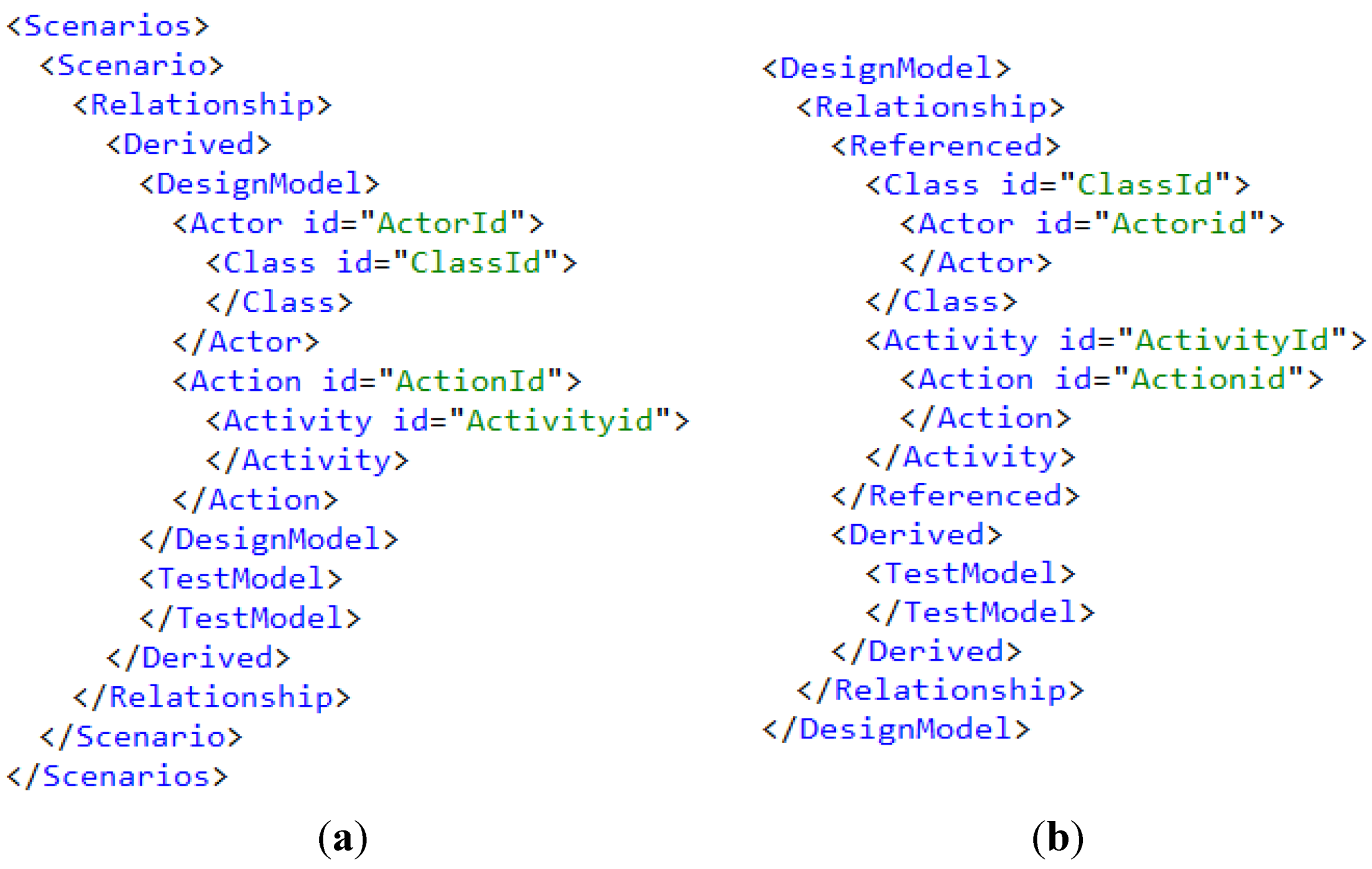
Figure 3a shows how the derived relationship is defined for each model part to another model part.
Figure 2.
RDML for each model.
Figure 2.
RDML for each model.
Similarly, the <ReferencedRelationship> element will have two subelements referring to the derived models. For example, in the DesignModel, RDML will contain two elements <RequirementsModel> and <TestModel> under the <ReferencedRelationship>.
Figure 3b shows how the referenced relationship is defined for each model part to another model part. A detailed view of RDML is given in the later sections.
Figure 3.
(a) requirements.RDML; (b) designmodel.RDML.
Figure 3.
(a) requirements.RDML; (b) designmodel.RDML.
Our approach starts with formulating the requirements, a scenario-based requirements elicitation. A major advantage of scenarios is that they allow for an effective exploration of users’ problems and goals [
17]. Scenarios encourage designers to envision outcomes before attempting to specify outcomes, thereby helping to make requirements more proactive in system development [
18]. Our scenario-based requirement elicitation comprises the following terminologies (see
Table 1):
Table 1.
Scenario based requirements—terminology.
Table 1.
Scenario based requirements—terminology.
| Terminology | Meaning |
|---|
| Scenario | A group of predefined actions and actors for accomplishing a goal |
| Objective | Objective or the main goal of the scenario |
| Actors | Actors are players involved either in the scenario or in an action |
| Precondition | Assumptions or conditions for achieving a particular goal |
| Postcondition | State of the system after executing the scenario |
| Trigger | A trigger is an interaction that starts the scenario. It could be either an action or a scenario |
| Action | A set of operations performed by different actors to achieve a subgoal |
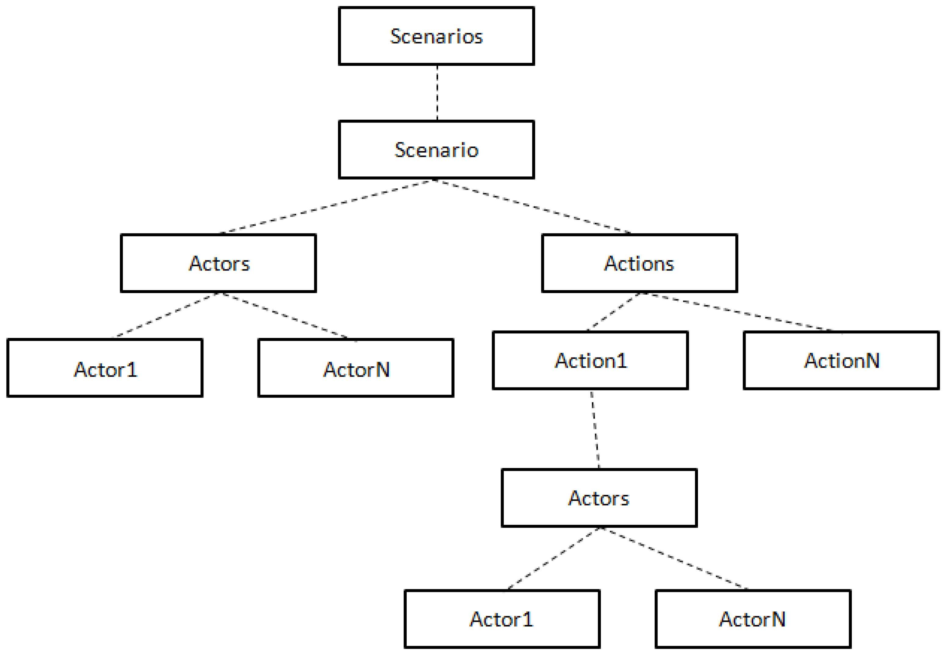
Typically, a business analyst will identify different scenarios from the informal requirements specification and is formally organized, so that the design analyst can derive the design models easily. The main tasks during this phase are identifying the scenarios, the actors, and the activities involved in the scenario. A formal scenario tree can be considered for organizing the scenario (see
Figure 4). The business analyst identifies different usage scenarios defined in the informal requirements and each usage scenario is further analyzed to find the different activities and actors. A scenario can contain any number of actors and actions. Each action is further analyzed to find the actors involved in this action. In the figure given below, scenarios are a collection of scenarios, which in turn is a collection of different actors and actions.
A scenario will have a unique id (scenario id) and source that points to a document where the requirement has been specified. Actor and action will also have a unique id. Actor will contain the necessary attributes and the action will contain the details of the action.
Our design model is derived from the structured requirements model defined above. Here, the design analyst refines the requirements model by finding, analyzing, and defining the actors and actions in different UML diagrams. From actors, appropriate classes are defined. Similarly, the actions are also grouped as functions into suitable classes and are described in UML activity diagrams. The main tasks involved in this phase are:
4.3. Defining the Relationship between Requirements Model and Design Model
Figure 3a is an example of a “requirements.RDML” file. Here the “Derived” element contains the design model and the test model. The “DesignModel” element defines the evolution of class diagram from actors and activity diagram from the actions in the requirements model. Similarly, the test model contains the test scenarios derived from the requirements model.
“Designmodel.RDML” contains the backward relationship to the requirements model defined in the “Referenced” element. The derived relationship to the test model will be defined in the “Derived” element.
Figure 3b is an example of designmodel.RDML.
Defining the relationship will help to define the fine granular evolution of design models from the requirements model. It will help to provide traceability during test generation and test execution, and helps to find the issues and inconsistencies in the requirements model, design model, and test model.
4.4. Test Model
Our test model is derived from the structured requirements model and the design model described in the above sections. Here, the test analyst refines the requirements model and the design model by finding different test scenarios. Each test scenario will be associated with a scenario described in the requirements model and the appropriate classes and activity diagrams in the design model. In this phase, the test analyst will also identify the expected input, expected output of each test scenario, actors and actions involved in the test scenario. How to model the test scenario using appropriate UML diagrams is part of our ongoing research. From the test model the executable tests will be generated.
4.5. Defining the Relationship of Test Models and Executable Tests with Other Models
“Testmodel.RDML” represents the relationship of test models with the requirements model and the design model. Derived relationships will contain the relationship between different parts of the test model with the requirements model and the test model. Referenced relationships will contain the backward relationship between test model and requirements model as well as design model.
TestModel.RDML file will have a main entry <TestScenario>. In the <TestScenario> element, the relationship is represented by the element <Relationship> that will contain the <DerivedRelationship> and <ReferencedRelationship> elements. The <DerivedRelationship> element will have two subelements referring to the derived models. The <ReferencedRelationship> will contain the relationship of the test model parts to the design model and requirements model. Similarly the “Test.RDN” represents the relationship of executable tests with test model, design model and requirements model.
5. Examples of RDML and Discussion
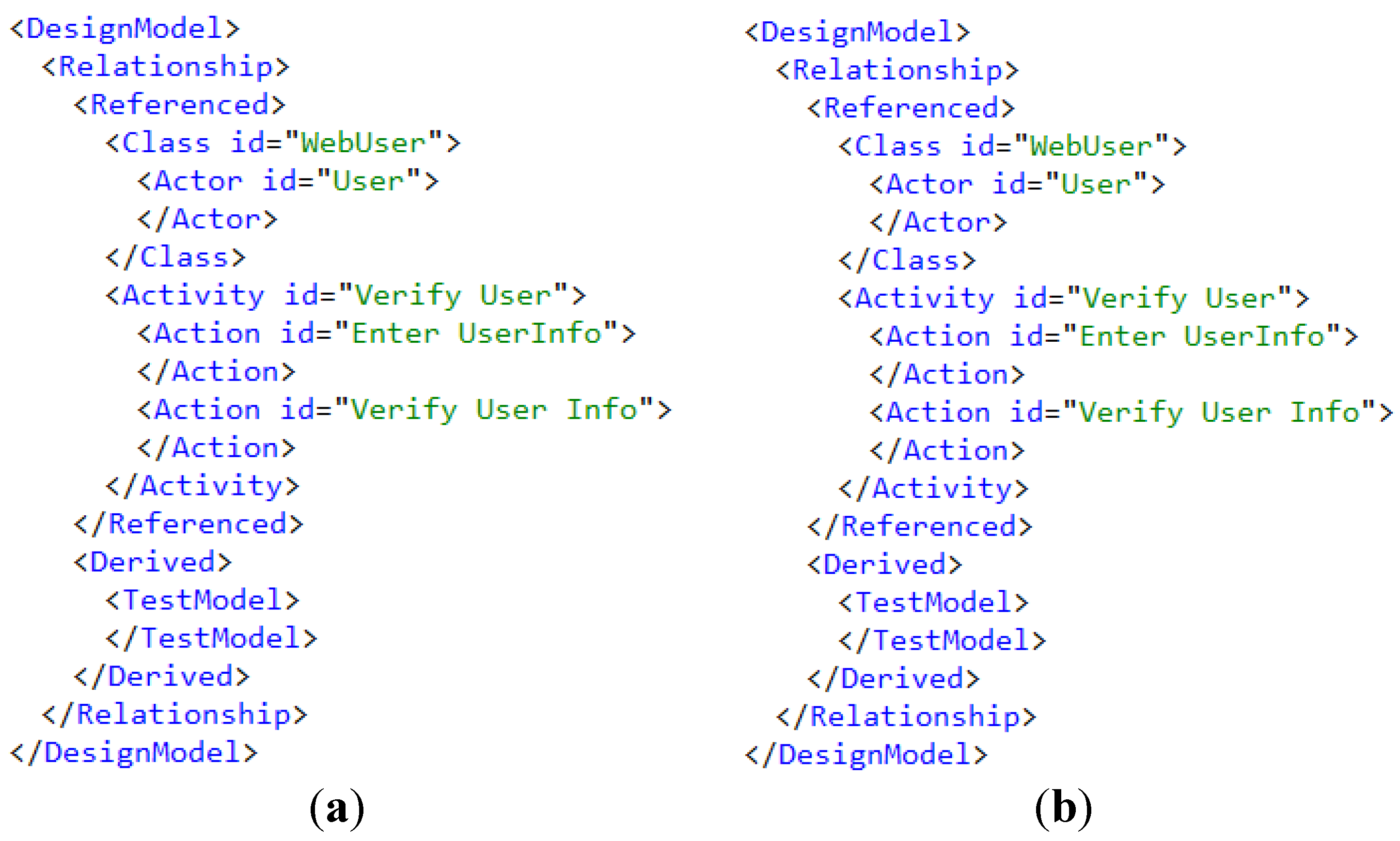
In this section, a “user log-in,” a functional requirement in an online library system, is represented as an RDML expression. Here the functional requirements and the design model are represented (see
Figure 5).
Here, the functional requirement is classified into different use case scenarios. The “online login” is taken as an example. In the functional requirements the “online login” scenario is identified, which contains an actor “User”. This “User” has a relationship with a class “WebUser” in the design model. An action identified in the scenario is the “VerifyUser” which has a relationship with the activities “EnterUserInfo” and “VerifyUserInfo” in the design model. In this example, we can see that the relationship between the two model/model parts is represented, which provides traceability. Entries in the requirements.rdml and designmodel.rdml can be related to test functions in the test model.
Figure 5.
(a) requirements.RDML; (b) designmodel.RDML.
Figure 5.
(a) requirements.RDML; (b) designmodel.RDML.
6. Benefits and Novelty
Traceability approaches in model-based testing in the literature only provide requirements traceability. None of the traceability approaches in model-based testing provides traceability between requirements model, test model and executable tests. Our approach provides the way to manage the link between the requirements model, design model, test model and the executable tests. Traceability between the different model artifacts and model elements can be achieved through our approach. The granularity of the traceability between model elements is another benefit of our approach. This granularity will help to find the design model elements, test model elements and executable tests associated with each requirement. Usage of RDML in test generation, and test generation from models is another benefit of this approach. Usage of standard XML in our approach will help to understand the concept easily. Since the models and tests are the integral parts of model-based testing, traceability between these artifacts and elements are important for navigating from requirements to executable test. This will help to find the coverage of requirements in test models and subsequent tests. Another benefit of the approach is to find the impact analysis on design models, test models and tests, when a requirement is changed. In the ongoing research we will undertake a case study for the proof of concept and quantify the benefits of our approach. This concept is part of ongoing research on model-based testing and the validation of this approach will be done as part of this research using different case studies.
7. Conclusions and Future Work
This paper has proposed an approach for defining relationships between the requirements model, design model, and test model and executable tests in a model-based testing approach. We have shown how these models can be defined and how to define the relationship between these models, thus filling the gap between different phases of the software life cycle. We have proposed a new formal way of defining the relationship between models using RDML (relation definition markup language) that uses standard XML technology. RDML helps to define the relationship between different models and parts of those models using a model-based testing approach. We have also classified and defined the relationship between models as derived and referenced relationships. Our approach tries to bridge the gap between the business analyst, system designer, and test analyst. Relationships between different models will help professionals to navigate from one model to another and to trace back to the respective requirements and the design model when system testing fails.
In our ongoing research, we will evaluate different modeling languages to define the scenarios formally in the requirements model in conjunction with UML diagrams to define the test model from the requirements model and design model. We will also provide traceability from each generated test to its respective requirements model, design model, and test model using the RDML definition of each model. A case study will be carried out to consider the efficiency and effectiveness of our approach.


