An Ontology-Based Approach to Enable Knowledge Representation and Reasoning in Worker–Cobot Agile Manufacturing


1
Department of Visual Assistance Technologies, Fraunhofer Institute for Computer Graphic Research IGD, 18059 Rostock, Germany
2
Institute of Computer Science, University of Rostock, 18059 Rostock, Germany
*
Author to whom correspondence should be addressed.
Future Internet 2017, 9(4), 90; https://doi.org/10.3390/fi9040090
Submission received: 20 September 2017
/
Revised: 15 November 2017
/
Accepted: 20 November 2017
/
Published: 24 November 2017
Abstract
:There is no doubt that the rapid development in robotics technology has dramatically changed the interaction model between the Industrial Robot (IR) and the worker. As the current robotic technology has afforded very reliable means to guarantee the physical safety of the worker during a close proximity interaction with the IR. Therefore, new forms of cooperation between the robot and the worker can now be achieved. Collaborative/Cooperative robotics is the new branch of industrial robotics which empowers the idea of cooperative manufacturing. Cooperative manufacturing significantly depends on the existence of a collaborative/cooperative robot (cobot). A cobot is usually a Light-Weight Robot (LWR) which is capable of operating safely with the human co-worker in a shared work environment. This is in contrast with the conventional IR which can only operate in isolation from the worker workspace, due to the fact that the conventional IR can manipulate very heavy objects, which makes it so dangerous to operate in direct contact with the worker. There is a slight difference between the definition of collaboration and cooperation in robotics. In cooperative robotics, both the worker and the robot are performing tasks over the same product in the same shared workspace but not simultaneously. Collaborative robotics has a similar definition, except that the worker and the robot are performing a simultaneous task. Gathering the worker and the cobot in the same manufacturing workcell can provide an easy and cheap method to flexibly customize the production. Moreover, to adapt with the production demands in the real time of production, without the need to stop or to modify the production operations. There are many challenges and problems that can be addressed in the cooperative manufacturing field. However, one of the most important challenges in this field is the representation of the cooperative manufacturing environment and components. Thus, in order to accomplish the cooperative manufacturing concept, a proper approach is required to describe the shared environment between the worker and the cobot. The cooperative manufacturing shared environment includes the cobot, the co-worker, and other production components such as the product itself. Furthermore, the whole cooperative manufacturing system components need to communicate and share their knowledge, to reason and process the shared information, which eventually gives the control solution the capability of obtaining collective manufacturing decisions. Putting into consideration that the control solution should also provide a natural language which is human readable and in the same time can be understood by the machine (i.e., the cobot). Accordingly, a distributed control solution which combines an ontology-based Multi-Agent System (MAS) and a Business Rule Management System (BRMS) is proposed, in order to solve the mentioned challenges in the cooperative manufacturing, which are: manufacturing knowledge representation, sharing, and reasoning.
1. Introduction: Evolution of Industrial Robotics
Indeed, the concept of a mechanical creatures and beings can be seen in very old civilizations such as ancient Egypt, Greece, and China. Passing by the era of Leonardo Da Vinci who sketched a mechanical man around 1495, to Nicola Tesla who is the first to demonstrate a radio controlled boat. However, the term robotics has been mentioned for the first time in 1941 by the science fiction writer Isaac Asimov to emphasis the idea of a new generation of intelligent machines which can take control of their actions and act autonomously. The term robot comes from the word robota in the Slavic language, this term has been introduced for the first time in Czechoslovakia in 1920 by the writer Karel Capek in his fiction “Rossunis Universal Robot”. Robota means a forced labor and has been used during the fiction to describe an artificial human-like creature who has been built to be used as an inexpensive worker. The fiction behind inventing the word robot has influenced the robot image which is still perceived in people minds till now. This image is a human-like being which is following the human orders to perform a variety of tasks such as walking, talking, and objects manipulation. Although this image is merely describing one specific type of robots which is the humanoid. A more generic definition of the robot which can be found in a dictionary is a machine which is capable of carrying out a complex series of actions automatically, especially one programmable by a computer. An IR extends the generic definition of the robot by specifying its functionality. An IR is an automatically controlled, reprogrammable, multipurpose manipulator with at least three degree of freedom, which may be either fixed stationary manipulator, or autonomous by fusing a stationary manipulator with a mobile base [1]. IRs are used to transport objects (e.g., material handling of work pieces between machines), in additive-manufacturing (e.g., assembly, welding, gluing, painting etc.), or in subtractive-manufacturing (e.g., milling, cutting, grinding, de-burring, polishing, etc.).
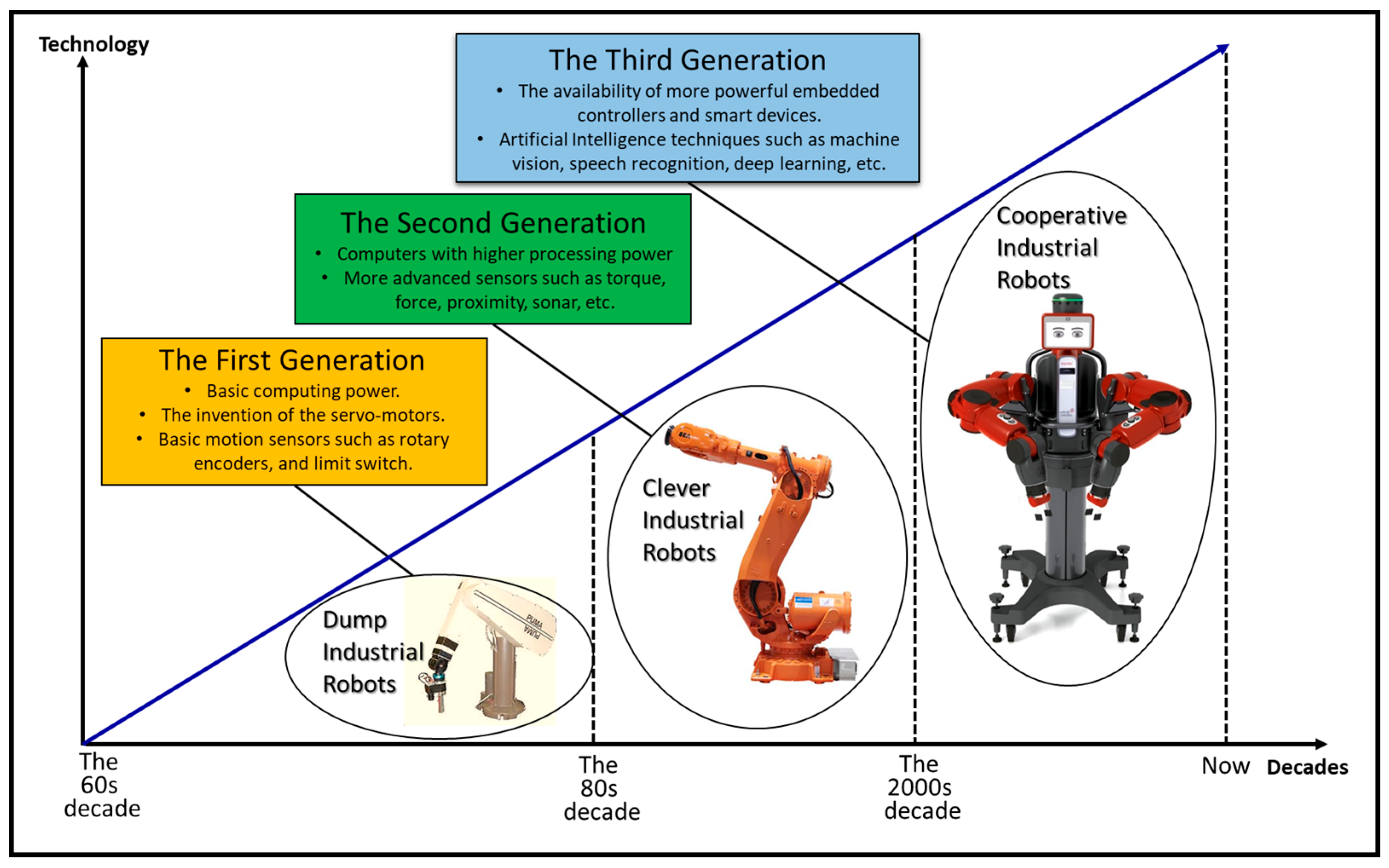
The history of the industrial robotics is closely tied to the creation of the robotics concept itself [2,3]. The first programmable IR implementation was in 1952 based on the designs of George Devol who also found the first IR commercial company Unimation. However, 1962 was the actual involvement of an IR in manufacturing, as General Motors cooperation installed the first Unimation IR in their automotive production line. This was the official start of the first IR generation which can be seen in Figure 1. The first generation of IR was a natural extension of the present technology at that time. The first IR generation is a simple mechanical manipulator which is capable of performing precise motion profiles with high speed, according to a fixed sequence of events. Therefore, it is a dump-IR. This is because it is very restricted to one program sequence regardless the changes in the work environment, thus it could not alter its actions. The second IR generation showed better signs of intelligence, due to the progress in the sensory technologies and the computing power by the beginning of the eightieth. This generation can be called the clever-IR, as it could determine the status of the outside world based on the feedback loop of its control system. Therefore, it could adjust its operation parameters such as velocity, acceleration, torque, or force. During the nineties, an intense research focused on the safety in industrial robotics, which derived new control techniques such as impedance and admittance control that allowed a collision free cooperation between the IR and the worker. This progress in safety techniques together with the advances in artificial intelligence technology led to the appearance of the third IR generation by the beginning of the current century. The third IR generation—which is commonly known as cobot—provides many different aspects of intelligence. Most of the available cobots can be programmed by a demonstrative teaching, this means that a worker without any programming background can move the cobot arm in a specific path with a specific speed then the cobot shall repeat the same motion profile. Also, the cobots are usually able to automatically stop their motion when a collision happens with their environment. They are also equipped with a variety of sensors especially cameras. All the cobots peripherals and inputs/outputs can be flexibly coded due to the manufacturing scenario, for instance the cobot can detect different products via customized image processing algorithms. Furthermore, the cobot operating systems are always very flexible to apply deep learning methods when it is needed in sophisticated task programming or learning.
Worker–cobot cooperative manufacturing is a novel trend in automation. The novelty in this trend comes from the idea of merging the advantages of both the worker and the cobot in the same shared work environment. On the one hand, the worker is a very important component of the manufacturing system, as he does not only add the high flexibility of taking the proper actions and decisions based on the current production situation, but also he is able during the manufacturing to use his natural senses intuitively to form complex solutions which are very hard to be programmed and executed by a cobot. On the other hand, the cobot is a very reliable component in terms of speed, accuracy, and weight lifting. A new generation of cobots is now available in the commercial market such as KUKA lightweight (KUKA Robotics, Augsburg, Germany), Rethink Baxter (Rethink Robotics, Boston, MA, USA), YuMi ABB dual arm (ABB Robotics, Zürich, Switzerland), and Universal Robots (Universal Robots, Odense, Denmark). Those cobots are able to provide the physical safety for the worker during the cooperative manufacturing.
One of the biggest advantages of the cooperative robotics is leveraging the manufacturing agility [4,5]. An agile manufacturing system is capable of responding rapidly and effectively to the unanticipated changes that take place in the production. The goal of the agile manufacturing is to proactively develop solutions which adapt with the customer needs. This research is proposing the cooperation between the worker and the cobot as a new approach to achieve the agile manufacturing goal. Thus, in order to accomplish this cooperation, a solution is needed to represent the shared environment and knowledge in the cooperative workcell. Putting into consideration the complexity of this environment, as it includes the production components which are continuously changing due to the definition of the agile manufacturing. Moreover, sharing and reasoning this information by the suitable technology is another challenge which is also introduced in this article. Therefore, during this research we propose a solution that can overcome these challenges. Furthermore, we demonstrate the solution over a case-study of two workers in cooperation with one cobot to manufacture a customized product.
In order to see the whole picture of cooperative manufacturing, a summary of some related work and the most influential challenges in cooperative manufacturing is briefly discussed in Section 2. This will guide the research later to focus on some specific problems which are the main concern of this article. In Section 3, the key concepts of the research will be highlighted. Those key concepts will be very beneficial when formulating the solution approach in Section 4. Accordingly, Section 5 will apply in detail the solution approach over a case-study. Finally, Section 6 will summarize and discuss the research, and screen the possible future work.
2. Related Work and Challenges in Cooperative Manufacturing
The challenges and the problems in the cooperative workcell are a broad subject of research, which can be seen from different angles. However, the most significant challenges are shown in Figure 2 and can be summarized as the following:
- Worker Safety: it is one of the earliest challenges which gained a lot of attention from the robotics community [6,7]. The safety in cooperative manufacturing extends from preventing the possibilities of any potential physical collision which might happen between the robot and the workcell components, to the psychological protection of the worker due to his cooperation with the robot. The research in [8] presents a real-time safety system which is capable of achieving the cooperative manufacturing with a standard IR – ABB-IRB-120. The system does not need to modify the standard robot hardware by adding any external sensors. Instead, it uses a virtual 3D representation of the cooperative workcell, to automatically control the robot speed based on the worker distance from it. The research in [9] is extensively discussing the different methodologies that can be used to grantee the physical and psychological safety in Human-Robot Interaction (HRI). The research in [10] introduces a neural network solution which dynamically compensates the robot path planning due to the changes in the work environment.
- Worker Activity Recognition: worker activity recognition is a very essential requirement to achieve the cooperative manufacturing, this is because it is the very first step to physically communicate with the cobot. The recognition could be for acquiring the worker status (i.e., busy or free), or for interacting with cobot during the manufacturing, for example to start or stop a cooperative task. The recognition of the worker activity can be also based on his natural movements during the manufacturing. For instance, picking and placing activity could be an indication that the worker is busy during that time, while holding a specific tool could express which operation is performed by the worker at the moment. The research in [11] proposes the use of the worker hand gestures to communicate with the cobot to add more flexibility to the manufacturing operations. Two modes of gesture recognition were defined due to this work. The first mode is an explicit gesture recognition, where a specific gesture which is not in the context of the manufacturing is detected. In other words, this mode of cooperation occurs when the worker is commanding the cobot directly via a set of a predefined gestures. The second mode is an implicit gesture recognition, where a specific gesture which is in the context of the manufacturing is detected, thus the cobot will perform a subsequent action. The research in [12] offers in detail a wide range of hand gestures which can be used by the worker during the cooperation with the cobot.
- Cooperative Workcell Integration in the Industrial Enterprise: The workcell is the smallest building block of the industrial enterprise, therefore it is important to define a method which can connect all the cooperative workcells horizontally over the shop floor, and vertically over the different layers of the enterprise. The research in [13] proposes the idea of linking the concept of holonic manufacturing architecture to the international society of automation (ISA)-95 standard to obtain this integration. On the horizontal level, the research proposes a supervisor holon which is providing coordination services when it is needed to cooperate outside the boundaries of the cooperative workcell. On the vertical level, the research defines the responsibilities of various types of holons and distributes them over the different layers of the industrial enterprise.
- Cooperative Workcell Self-organization: a form of self-organization must exist in the cooperative workcell to fulfill the purpose of the cooperative manufacturing. Self-organization is an adaptation mechanism which is used by the cooperative workcell to overcome the variations in the manufacturing environment. The articles in [13,14,15] mention four important sources of variations that can be found in the cooperative workcell. The first source comes from the variation in the production requirements such as the production customization and volume. The second source of variation is due to the change in the time which is taken from the worker to accomplish a specific task. The third source of variation occurs due to the change in the number of co-workers or cobots during the manufacturing, and finally the last source of variation can happen when there are more than one co-worker or cobot in the manufacturing workcell, each has different set of skills or tasks. The research in [16] addresses the problem of self-organization of a group of cooperative mobile robots. The research proposes an ontology-based concept to obtain the self-organization, however it does not show a clear implementation of this concept.
- Cooperative Tasks Planning and Scheduling: cooperative tasks planning means to select at least one cobot and one co-worker to assign a cooperative task. The researches in [13,17,18] assign the cooperative task based on matching the skills of the available workers and cobots with the required product recipe. Furthermore, the proposed control solution monitors the productivity of the workers and the cobots to balance the task assignment process. An automatic assembly planning of complex products has been considered in [19], the research provides a method which utilizes the information stored into a Computer-Aided Design (CAD) model to generate the assembly sequence, and then monitors the assembly execution in order to support the assembly joining plans. cooperative tasks scheduling is the problem of selecting the right sequence of executing a group of standing tasks. This problem is mainly affecting the overall efficiency of the cooperative workcell. The research in [20] shows the effect of the cooperative workcell scheduling by comparing two different techniques which are based on First Come First Serve (FCFS) and Johnson’s algorithm. Then, it proves that Johnson’s scheduling method will always give better results than FCFS by minimizing the overall makespan.
- Manufacturing Knowledge Representation: in order to obtain the cooperation between a cobot and a human co-worker, all the knowledge in their shared environment including themselves should be represented in form of meta-data. Descriptive meta-data are essential to give a meaning of the objects, tasks, and operations within the cooperative workcell. Structural meta-data are required to structure bonds between the objects to compound new descriptive meta-objects, this also can be done by associating new attributes to an existing object. Also, the structure meta-data can be used to define the parent-child relation among the objects. Finally, administrative meta-data is required to control the cooperative task assignment and the cooperation planning, management, and execution.
- Manufacturing Knowledge Sharing: the knowledge cannot be shared unless a proper mean of communication allows the knowledge exchange. In the context of cooperative manufacturing, the knowledge format should be understandable by both the human worker and the cobot. Therefore, finding the proper approach which can provide a common natural communication language between the human and the cobot is a crucial focus of this article.
- Manufacturing Knowledge Reasoning: after representing the knowledge and exchanging it among the different entities in the cooperative manufacturing system, a specific reasoning for this knowledge is necessary to be performed by every entity in the system to adapt to the variations in the production demands. The reasoning in the cooperative manufacturing is needed as every component in the system must have certain responsibilities and behaviors. Therefore, every component has to understand the production demands and the overall status of the workcell, thus they can comprehend the manufacturing knowledge and fulfill their functions.
The previously discussed related work shows that the information exchange among the cooperative workcell components is a necessity to achieve the cooperation. However, the information exchange at the shown related work was based on a simple message which contains a String data type. In complex interaction scenario which requires to represent the relations between the cooperative workcell components and the actions that can be taken by every component, a new approach is needed beyond the simple String messaging. Accordingly, this article extends our previous work which can be seen in [11,13,14,15,17,20]. For that reason, during this article we only focus on the last three mentioned challenges which concern the cooperative manufacturing knowledge representation, sharing, and reasoning.
3. Key Concepts
3.1. Ontology-Based Multi-Agent System
A software agent is a computer system situated in a specific environment that is capable of performing autonomous actions in this environment in order to meet its design objective [21]. An agent is autonomous by nature, this means an agent operates without a direct intervention of the humans, and has a high degree of controlling its actions and internal states. In order to achieve this autonomy, an agent must be able to fulfil the following characteristics:
- Responsive: an agent is capable of perceiving its environment and respond in a timely fashion to the changes occurring in it.
- Pro-active: an agent is able to exhibit opportunistic, goal directed behavior and take initiative.
- Social: an agent can interact with other artificial agents or humans within its environment in order to solve a problem.
Conceptually, an agent is a computing machine which is given a specific problem to solve [22]. Therefore, it chooses certain set of actions and formulates the proper plans to accomplish the assigned task. The set of actions which are available to be performed by the agent are called a behavior. The agent behaviors are mainly created by the agent programmer. An agent can execute one or more behavior to reach its target. The selection of an execution behavior among others would be based on a certain criterion which has been defined by the agent programmer. Building an execution plan is highly depending on the information which the agent infers from its environment including the other agents. An MAS is a collective system composed of a group of artificial agents, teaming together in a flexible distributed topology, to solve a problem beyond the capabilities of a single agent.
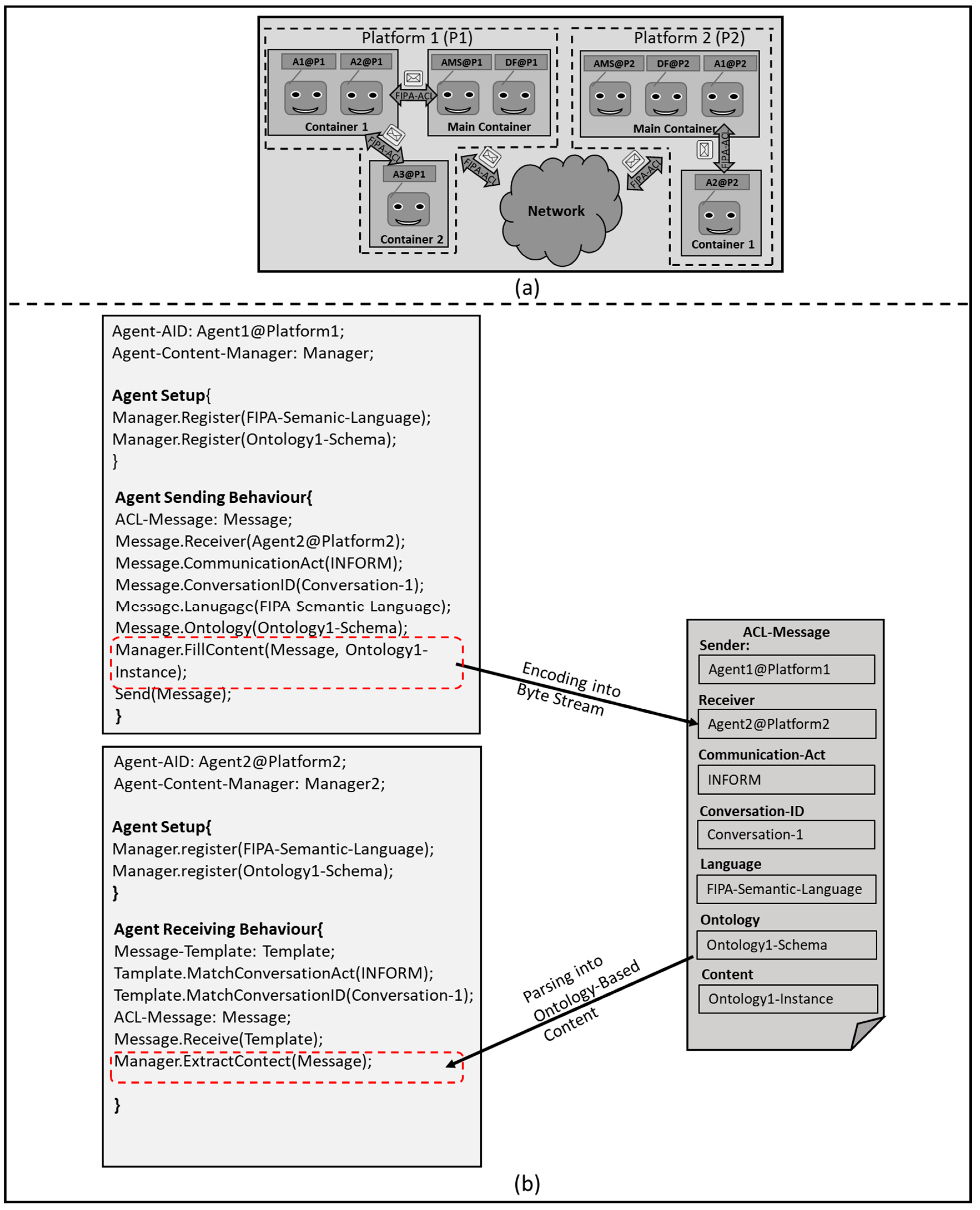
JAVA Agent Development Environment (JADE) is a distributed MAS middleware framework as it is shown in Figure 3a [23]. Each JADE instance is an independent thread which contains a set of containers. A container is a group of agents run under the same JADE runtime instance. Every platform must contain a main container. The main container contains two necessary agents which are: an Agent Management System (AMS) and a Directory Facilitator (DF). AMS provides a unique ID for every agent under its platform to be used as an agent communication address. While the DF announces the services which agents can offer under its platform, to facilitate the agent services exchange, so that every agent can obtain its specific goal. JADE applies the reactive agent architecture which complies with the Foundation for Intelligent Physical Agent (FIPA) specifications, and provides a graphical interface to deploy and debug an MAS. FIPA is an IEEE Computer Society standards organization that promotes agent-based technology and the interoperability of its standards with other technologies [24]. JADE agents use FIPA-Agent Communication Language (FIPA-ACL) to exchange messages either inside its own platform or with another platform in a distributed MAS.
The interaction mechanism for sending and receiving an ontology-based ACL-message between two JADE agents is illustrated in Figure 3b. Every JADE agent must have an Agent Identification (AID). The AID is composed of a unique name for the agent over a specific platform, and it is used as an address for the agent to send or receive a message. Also, every agent must have a setup method. The setup method is automatically triggered after the agent creation. The main function of the setup method is to initialize the required parameters and behaviors needed for the agent to perform its tasks. In order to complete a communication process between two agents, one agent must have a behavior which is responsible for constructing and sending an ACL-message, the other agent must have a behavior which is responsible for receiving the ACL-message. An ACL-message is composed from variety of fields, and it must have at least a Sender and a Receiver AIDs. Other fields such as the Communication-Act and the Conversation-ID are necessary to distinguish the message at the receiver side. The Communication-Acts are defining the ACL-message in terms of standard FIPA actions or functions, for instance a communication-act field can contain INFORM, REQUEST, CONFIRM, etc. The Conversation-ID parameter can be any unique string to distinguish or record a specific conversation topic or thread among the agents.
The content field of an ACL-message contains a String data type in case of simple agent conversation. However, in a complex agent conversation, an ontology-based content will be the proper conversation method. In order to communicate via agent ontologies, every agent must deploy a content-manager. The content-manager registers a common language of conversation between the agents [25]. The FIPA Semantic Language (FIPA-SL) is not mandatory but preferable in a complex JADE conversation. FIPA-SL is a human readable language which defines the syntactic rules needed to parse or encode an ontology-based content. Also, the content-manager registers the common ontology schemas. The ontology schema is defining the abstract structure pattern and the semantics needed to construct or interpret an ontology-based ACL-message. At the sender agent side, the content-manager checks the semantics of the sent ACL-message based on a common ontology schema, and decodes that message into a stream of Bytes via FIPA-SL. At the receiver side, the content-manager parses the received ACL-message into a human readable content via FIPA-SL, and structures it based on a common ontology schema.
3.2. Rule-Based System
A rule-based system is a form of an expert system which usually uses an ontology-based representation to codify the information into a knowledge-base that contains facts which can be used later in the reasoning stage [26]. A rule-based system depends on two kinds of memory as it is shown in Figure 4a. The working memory holds the facts which present the domain knowledge, while the production memory holds a set of rules. A rule is a declarative method to represent the knowledge in a concise, non-ambiguous conditional statement. The reasoning engine is the brain of the rule-based system which solves a given problem by matching the present facts with the existing rules. Initially, an external event must trigger a reasoning session in the reasoning engine. When one or more fact matches the IF condition in one or more rule statement, the THEN conclusion will be inferred and a new facts will be generated, then the new facts will be updated into the working memory. A new reasoning session will be triggered automatically, every time a match between a fact and a rule condition occurs. A chain of reasoning sessions will take place until no more matching happens. An example of a reasoning chaining can be seen in Figure 4b.
The reasoning engine organizes and controls the flow of the solution route based on one of the following reasoning methods [27]:
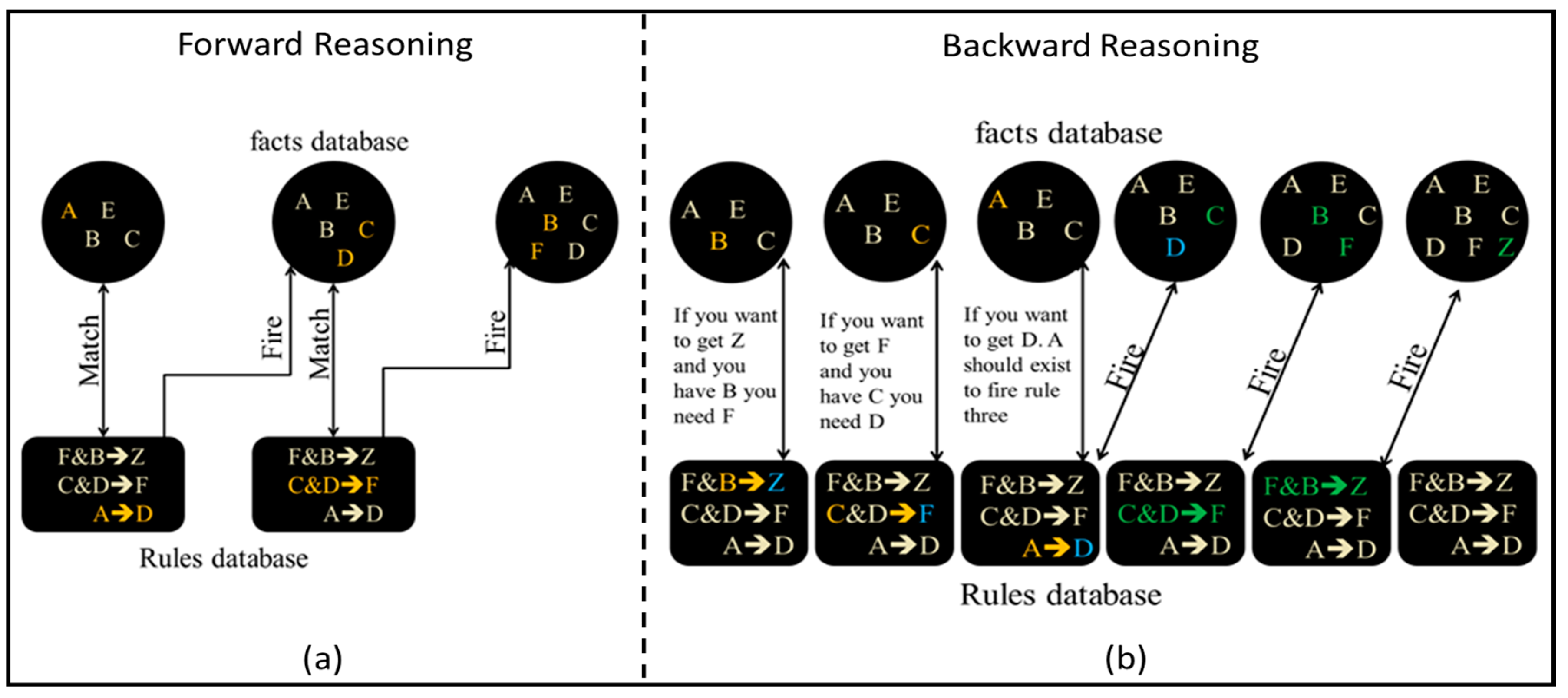
- Forward reasoning: in forward chaining, the rule-based system starts with the initial facts and derives new facts whenever a rule matches a fact. The reasoning engine goes through consequence of rules firing to find its final goal, which ultimately leads to find the solution route from the initial facts to the final goal in a forward reasoning style. An example of the forward chaining is shown in Figure 5a.
- Backward reasoning: in backward chaining, the rule-based system starts from the final goal, then it finds which rules must be fired to lead to this goal, therefore the reasoning engine can determine the facts which are needed to reach the final goal. During the backward chaining a consequence of sub-goals will appear, which ultimately leads to find the solution route from the final goal to the initial facts in a backward reasoning style. An example of the backward chaining is shown in Figure 5b.
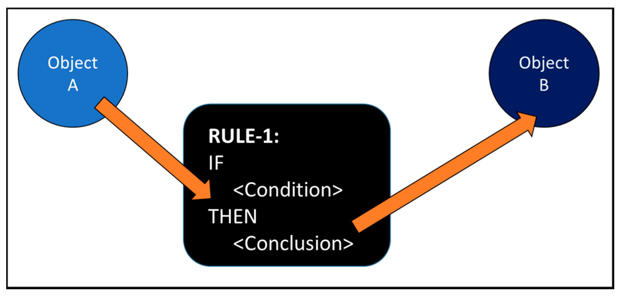
Drools is a BRMS that has been created by jboss organization, therefore it adds more features than a regular rule-based system [28]. As it provides a tool for a rule-based solution creation, managing, deploying, and analyzing. Drools has the capability of applying a hybrid chaining reasoning. A hybrid chaining reasoning is a mix between the forward and the backward chaining which can be more efficient in some cases than both. Drools applies two mechanisms of reasoning, the first mechanism is called a stateless reasoning. In this technique. The reasoning engine does not take into consideration the change in the values of the facts during executing the reasoning session. Therefore, the rules which are based on these facts will not be fired. The second mechanism is called a stateful reasoning. In this technique, the reasoning engine considers the change in the values of the facts during executing a reasoning session. Therefore, the rules which are associated with these facts will be fired. The stateless reasoning session can be used to derive new results based on facts, while stateful reasoning session is useful in more complicated scenarios such as diagnosis or monitoring. Moreover, Drools evolves the pattern matching Rete algorithm to ReteOO algorithm [29]. ReteOO denotes the enhancement of Rete algorithm by combing it with other Object Oriented (OO) concepts such as abstraction, inheritance, and encapsulation. The basic interactivity between Drools object via ReteOO pattern matching can be seen in Figure 6. In Figure 6, the attributes of an instance of object-A matches the conditional part of the rule. Therefore, the rule creates a new instance of object-B which holds attributes that assigned by the conclusion part of the rule.
Drools can be seen as a deliberative agent which can be coded by a higher level language than a symbolic one, to model the agent world and its reasoning scheme. Furthermore, Drools affords many other privileges in the following sense:
- Declarative programming: rules programming technique is far easier to express complicated solutions for difficult problems, and to verify those solutions as well. Furthermore, Drools provides a decision making table option in a form of MS-excel, which makes it possible for someone with no coding background to read and modify the rules.
- Logic and data separation: as a direct result of the ReteOO algorithm, the data locates in the domain of the object, while the logic locates in the domain of the rules. This can be very useful to provide different levels of authorities and accessibilities for the users.
- Centralization of the knowledge: by creating a single knowledge base which contains all the facts, the knowledge will be accessible and shared by all the agents. Thus, problems can be solved in faster and more efficient ways.
- Speed and reliability: using the available options such as ReteOO, hybrid reasoning technique, or stateful reasoning session makes Drools very fast and reliable tool.
3.3. Holonic Control Architecture
In the late sixties, the term holon has been introduced for the first time by philosopher Koestler [30]. Koestler developed the term as a basic unit in his explanation of the evolution of the biological and social structures. Based on his observations that organisms (e.g., biological cells) are autonomous self-reliance units, which have a certain degree of independent control of their actions, yet they still subject to higher level of control instructions. His conclusion was that any organism is a whole “holos” and a part “on” in the same time, which derived the term holon [31]. The concept of holon has been adopted in the early nineties by the intelligent manufacturing systems (IMS) consortium, to define a new paradigm for the factory of the future.
The following terminologies has been defined by the IMS to provide a better understanding of the Holonic Control Architecture (HCA):
- Autonomy: the capability of the holon to create and control the execution of its own plans.
- Cooperation: a process whereby a set of holons develop mutual plans to execute them together.
- Holarchy: a system of holons which cooperate to achieve a goal or objective. The holarchy defines the basic rules for cooperation of the holons and thereby limits their autonomy.
The HCA is a distributed control and communication topology which divides the manufacturing process tasks and responsibilities over different holon categories. Product-Resource-Order-Staff-Architecture (PROSA) which can be seen in Figure 7b is the most known HCA model [33]. The PROSA basic holons are:
- Product Holon (PH): is responsible for processing and storing the different production plans which are required to insure the correct manufacturing of a certain product. Different production plans are needed to manufacture different products within the same workcell. Therefore, the PH has to match the required product type with its plans.
- Order Holon (OH): is responsible for composing, managing the production orders. Furthermore, in a small scale enterprise, it should assign the tasks to the existing operating resources and monitor the execution status of the assigned tasks.
- Operational Resource Holon (ORH): is a physical entity within the manufacturing system, it can represent a robot, machine, worker, etc.
4. Solution Approach
4.1. CPROSA-Holarchy
In the context of the cooperative agile manufacturing, we found that it is necessary to modify the PROSA model. Therefore, a new holon is introduced by this research which is the Customer Holon (CH). A CH is deployed on the customer platform to provide a User Interface (UI) for the customer to select and customize the product order. Furthermore, it interacts with the PH to trigger a new production order. Therefore, we are going to refer to our modified PROSA holarchy as CPROSA which can be seen in Figure 8.
While the HCA is a conceptual model that focuses on the holons functionalities and responsibilities, it does not specify a certain technology to apply that concept. The autonomous agent technology is a general purpose solution which can implement the HCA [34]. Thus, during this research, JADE framework has been selected to implement the proposed CPROSA-holarchy. JADE empowers the object oriented concepts such as abstraction and inheritance, which makes it very suitable for applying the CPROSA-holarchy. For example, a Worker Holon (WH) can have many different instances originate from it, yet every WH instance can act differently than the others. Figure 8 illustrates the main concept to implement an agile cooperative manufacturing workcell, which can contain different workers and cobots as operational resources, the manufacturing workcell can simultaneously process different customized orders from various customers. Using JADE to implement the CPROSA-holarchy empowers another very strong concept which is the agent communication via ontology [35]. The CPROSA-holarchy implements many different objects. This is not only obligating the holons to send or receive messages with objects content, but also it obligates them to express relations between these objects and perform actions over them [36].
The term ontology can sometime be considered as vague, therefore we state below the most suitable definitions of ontologies for our research [37,38,39].
- An ontology defines the basic terms and relations comprising the vocabulary of a topic area as well the rules for combining terms and relations to define extensions for this vocabulary [40].
- An ontology is a formal, explicit specification of a shared conceptualization [41].
- An ontology is a logical theory accounting for the intended meaning of a formal vocabulary [42]. i.e., “it is a commitment to a particular conceptualization of the world”.
- An ontology provides the meta-information to describe the data semantics, represent knowledge, and communicate with various types of entities (e.g., software agents and humans) [43].
- An ontology can be described as “means of enabling communication and knowledge sharing by capturing a shared understanding of terms that can be used both by humans and machine software” [44].
All the previous definitions draw the complete picture of the ontology meaning in the context of our research. Thus, an ontology is a conceptual tool to represent and create a common understanding for the manufacturing workcell entities (i.e., holons). Furthermore, this common understanding would enable to exchange, reuse and extend the manufacturing knowledge. JADE supports an ontology-based MAS by defining three types of schemas:
- Terms: expressions that indicate entities that exist in the MAS and that agents may reason about. Terms can be seen as primitives which are atomic data types such as strings or integers, and concepts which are complex structure such as objects.
- Predicates: expressions that describe the status of the world and the relationships between the concepts.
- Actions: expressions that describe routines or operations that can be executed by an agent.
4.2. CPROSA-Holon Model
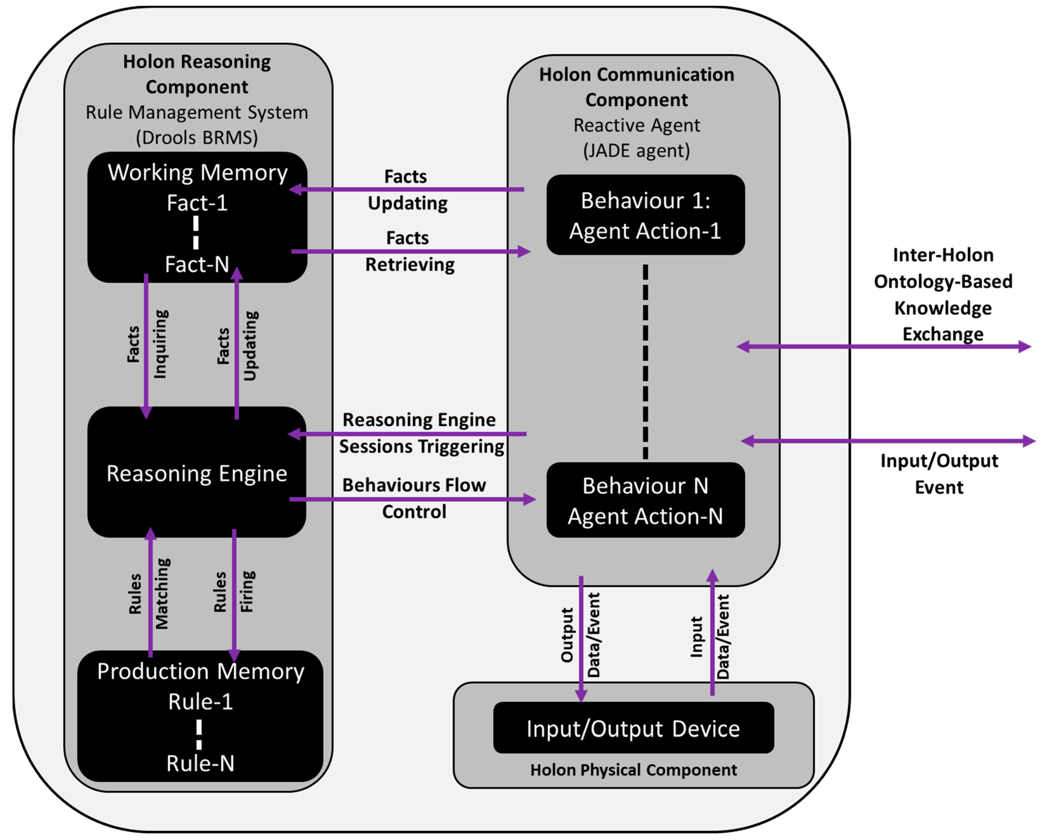
Figure 9 explains the structure of the CPROSA-holarchy. Each holon is composed of three components. The first component is the physical component, which is responsible for dealing with the input/output (I/O) data and events. The source of the I/O data and events is an automation device which could be a controller, a sensor, or a Human-Machine Interface (HMI). Therefore, the holon can interact with the human or the machine via the physical component. The second component is the communication component which is responsible for sending, receiving the information. The communication component can be implemented as a JADE agent. Therefore, the holon can interact with the other holons via the communication component. The third component is the reasoning component which is responsible for processing and reasoning the information. The reasoning component can be implemented as a Drools BRMS.
5. Case-Study
5.1. Case-Study Description
During this research we selected a specific case-study where two workers are cooperating with one cobot as it can be seen in Figure 10a. In this scenario, the customer initializes a production order by selecting the main features of the product and the required number of units. A centrifugal pump has been chosen as a customized product example. When the customer sends the production order to be executed, the cobot will pick and place the proper amount of the product parts from their storage space to the worker workstation, where the worker is able to assemble the product.
The goal of the case-study is to implement the solution concept. Accordingly, the deployment CPROSA-holarchy via JADE is shown in Figure 10b, JADE framework contains four containers which present the previously described CPROSA holons. Two CHs can be found in this case-study as it can be seen in Figure 10c. Both the CHs have a similar UI. The UI of the CH is providing a tool for ordering a specific product with certain features (i.e., parts). The customer selects the basic features and defines the needed amount of the product then sends the order to the PH. A customized centrifugal pump can be manufactured in this case- study. The UI of the pump holon can be seen in Figure 10d. The pump has four features which are the casing, the electrical-motor, the impeller and the shaft. When a PH receives a product order from the CH, it constructs the building plans for this product order as it will be discussed later in detail. The PH also has the ability to rearrange the orders or modify them before sending them to the OH.
The OH is responsible for collecting the orders from the PH as it is shown in Figure 10e. Simultaneously the OH discovers the existence of the operation resources. Furthermore, it starts and stops the production process. Two WHs (WH1, WH2) and one Robot Holon (RH) can be found as operation resources in this implementation as it is shown in Figure 10f. The function of the workers within this case-study is to perform an assembly operation of the customized pump orders, while the function of the cobot is to pick and place the right amount of the pump features to the worker workstation. As we do not have a robot hardware during this implementation, we assumed that the cobot always takes two seconds to pick and place one pump. Therefore, the RH multiplies the number of pumps by two to obtain the overall time needed for the whole pick and place operations. Accordingly, the RH can have two statuses, either busy or free. Another status is required for the WH which is a reserve status. In the reserve status the WH is waiting the cobot to load at least one pump, therefore the worker can start the assembly operation and subsequently the WH status turns to be busy. The WH stays in the busy status till the worker presses the task-done button, then the WH status would be free.
5.2. Case-Study Ontology
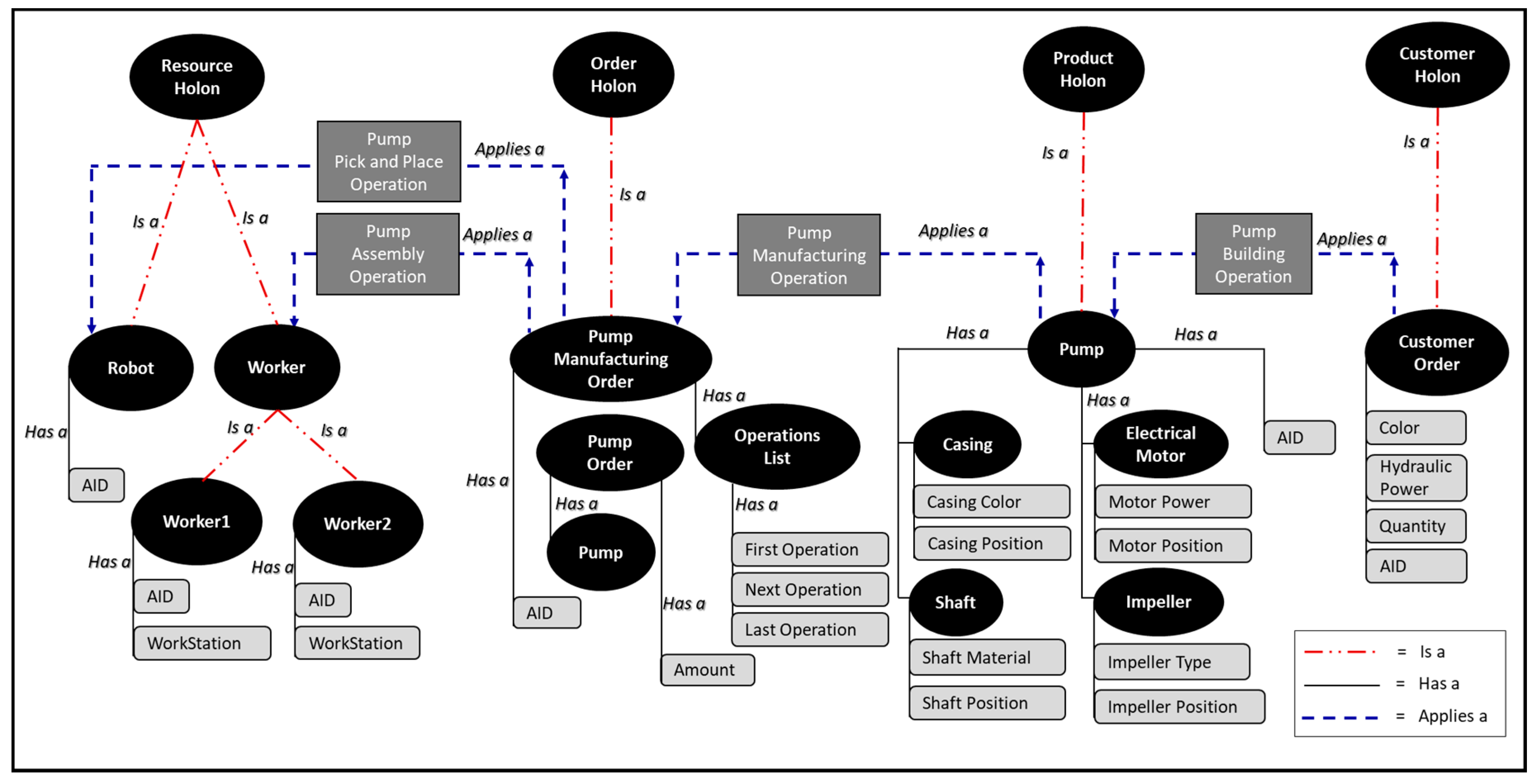
As has been discussed earlier at the solution concept, JADE is using three different types of schemas to construct its ontology. Figure 11 shows all the required schemas used to build the case-study ontology. The first set of schemas which can be seen in Figure 11 are the terms (i.e., concepts and primitives):
- Customer-Order: a schema which encapsulates some attributes such as the required color, the needed hydraulic power, and the required amount of units. Also, it contains an AID as every customer-order is an agent which needs an ID.
- Casing: a shared feature between the pump and the compressor. The casing schema contains two attributes which are the casing color, and position at the features storage space.
- Electrical-Motor: a shared feature between the pump and the compressor. The motor schema contains two attributes which are the motor electrical power, and position at the features storage space.
- Impeller: a unique feature of the pump. The impeller schema contains two attributes which are the impeller type, and position at the features storage space.
- Shaft: a unique feature of the pump. The shaft schema contains two attributes which are the shaft material, and position at the features storage space.
- Pump: a concept schema which encapsulates many other schemas under it, those schemas are the casing, electrical-motor, shaft, and impeller. Every pump is an agent, therefore it must contain an AID attribute.
- Pump-Order: this schema extends the pump schema by adding the required amount of units.
- Operations-List: a schema which includes a list of operations which can be used to manufacture either a pump or a compressor. The schema can be used to manufacture a product which needs three operations or less.
- Pump-Manufacturing-Order: a schema which combines a Pump-Order schema and an Operations-List schema. Also, it has an AID attribute as it acts as an agent.
- Worker: a schema which contains two attributes, the first one is the worker AID, and the second is the worker location within the workcell (i.e., workstation). The worker agent is providing an UI for the worker for providing the assigned task and inquiring the task done event (see Figure 10f). Two instances of the worker agent exist in this case-study scenario. As has been mentioned before in Section 5.1, the worker can have three statuses. A free status when there are no product orders or the production is not started. A reserve status when the worker is waiting the first product unit to be placed by the cobot. A busy status while the cobot is still handling the orders and till the worker triggers the task-done button.
- Robot: a schema which contains one attribute which is the robot AID. The robot schema does not have a workstation attribute because in this specific case-study, we have one cobot which is responsible for the pick and place. Therefore, the location of the cobot is not necessary required, however in case of more than one cobot this attribute could be important. The robot agent is providing an UI to show the assigned task and the status of the cobot (see Figure 10f). As has been mentioned before in Section 5.1, the cobot can have two statuses. A free status when there are no product orders or the production is not started. A busy status when the cobot is picking and placing the production orders. A timer of two second has been assigned to every pick and place operation.
The second set of schemas are the predicate as shown in Figure 11 and explained as following:
- (concept-x) <Is-a> (concept-y): usually a relation between two concept schemas. This relation is similar to the object oriented abstraction. Thus, this predicate expression has been used to express the parent-child relationship between the concepts.
- (concept-x) <Has-a> (attribute-x): usually a relation between a concept and an attribute, an attribute can be a concept schema or a primitive. This relation is similar to object oriented inheritance. Thus, this predicate expression has been used to form sophisticated objects from simpler ones.
- (agent-x) <Applies-an> (action-x): usually a relation between a concept and an action schema. A concept uses this predicate expression to trigger one or more than one actions at the same time. The action schemas will be discussed below in detail.
The third set of schemas are the action as shown in Figure 12 and explained as following:
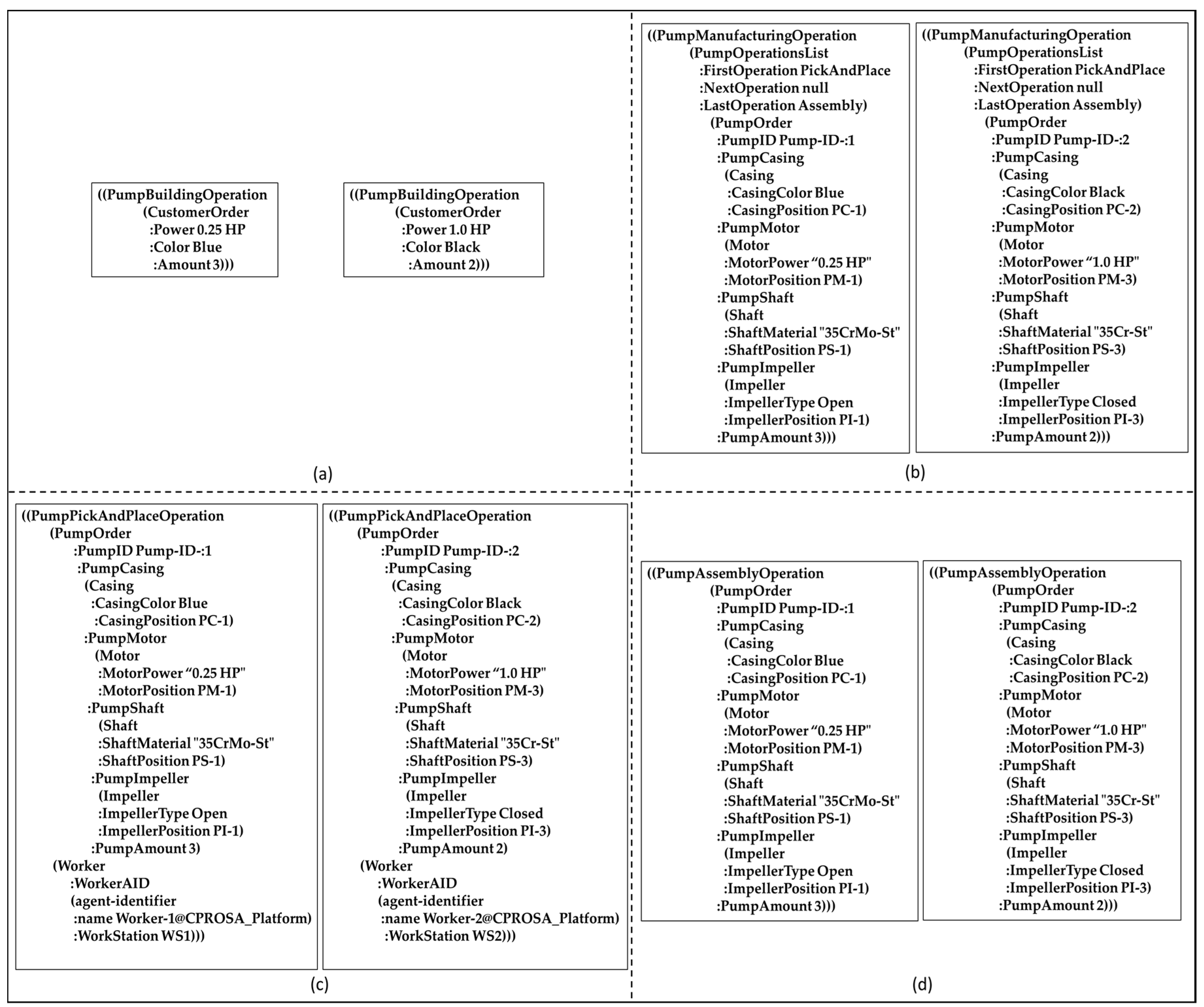
- Pump-Building-Operation: this action schema expects a pump customer-order concept as an input, and it can be deployed by either customer-1 or customer-2 agents. An example of this operation can be seen at the ACL-message content in Figure 12a.
- Pump-Manufacturing-Operation: this action schema expects a Pump-Order and a Pump-Operations-List concept schema as an input, and it is deployed by the pump agent. A detailed example of this operation can be seen at the ACL-message content in Figure 12b.
- Pump-Pick-And-Place-Operation: this action schema expects two concept schema inputs; the first concept schema input is the pump-order which contains the detailed specifications of the pump. Therefore, the cobot can use this information especially the pump features positions to perform the pick operation. The second concept schema input is the target worker. Therefore, the cobot can use the worker workstation location to place the pump features at this location. This action schema is deployed by the orders agent to assign a task to the robot agent. A detailed example of this operation can be seen at the ACL-message content in Figure 12c.
- Pump-Assembly-Operation: this action schema expects one concept schema input which is the pump-order. This operation is beneficial for the worker to provide him with the required features to build a customized pump. Moreover, it provides the amount of required units. This action schema is deployed by the orders agent to assign a task to any of the worker agents based on their status. A detailed example of this operation can be seen at the ACL-message content in Figure 12d.
5.3. Pump-Orders Building
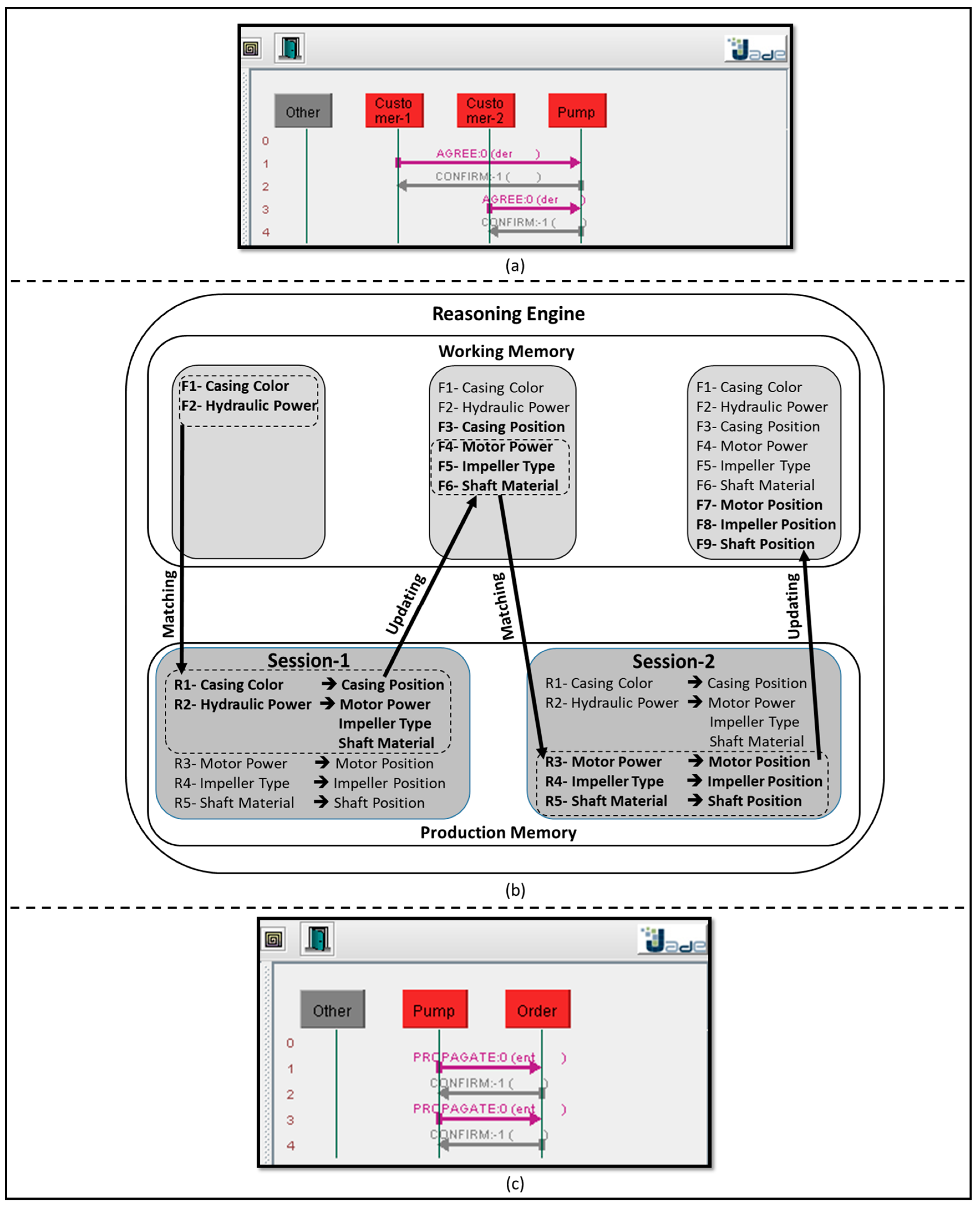
Figure 13a shows JADE interaction scenario among the CHs (i.e., customer-1 agent and customer-2 agent) and the PH (i.e., pump agent). In this scenario, customer-1 agent sends the product order in form of an ACL-message with an AGREE communicative act to the pump agent. The AGREE-message contains a Pump-Customer-Order as has been shown in Figure 12a. When the AGREE-message is received by the pump agent, the pump agent confirms the receiving by sending back a CONFIRM-message to customer-1 agent. The same mechanism is used again between cusomter-2 agent and the pump agent. Two facts can be extracted by the pump agent from the received customer order AGREE-message, which are the casing color and the hydraulic power.
Processing the customer-order to build a pump order is done via a forward chaining reasoning and can be seen in Figure 13b. When a new customer order AGREE-message is received by the pump agent it triggers the reasoning session-1. The casing color fact derives new fact which is the casing position. While the hydraulic power fact derives other three facts which are the motor power, the impeller type, and the shaft material. Those new facts are being updated to the PH working memory. When the reasoning engine realizes that some of the new facts in the working memory are matching some of rules in the production memory, it triggers the reasoning session-2. In this session, the motor power fact derives the motor position fact, the impeller type fact derives the impeller position, and the shaft material derives the shaft position. The new facts at the PH working memory can be now used to formulate the pump manufacturing operation message which has been shown before in Figure 12b. The communication act of the pump manufacturing operation message is PROPAGATE-message. The same interaction scenario which has been shown in Figure 13a is followed between the PH and the OH as can be seen in Figure 13c.
5.4. Pump-Orders Execution
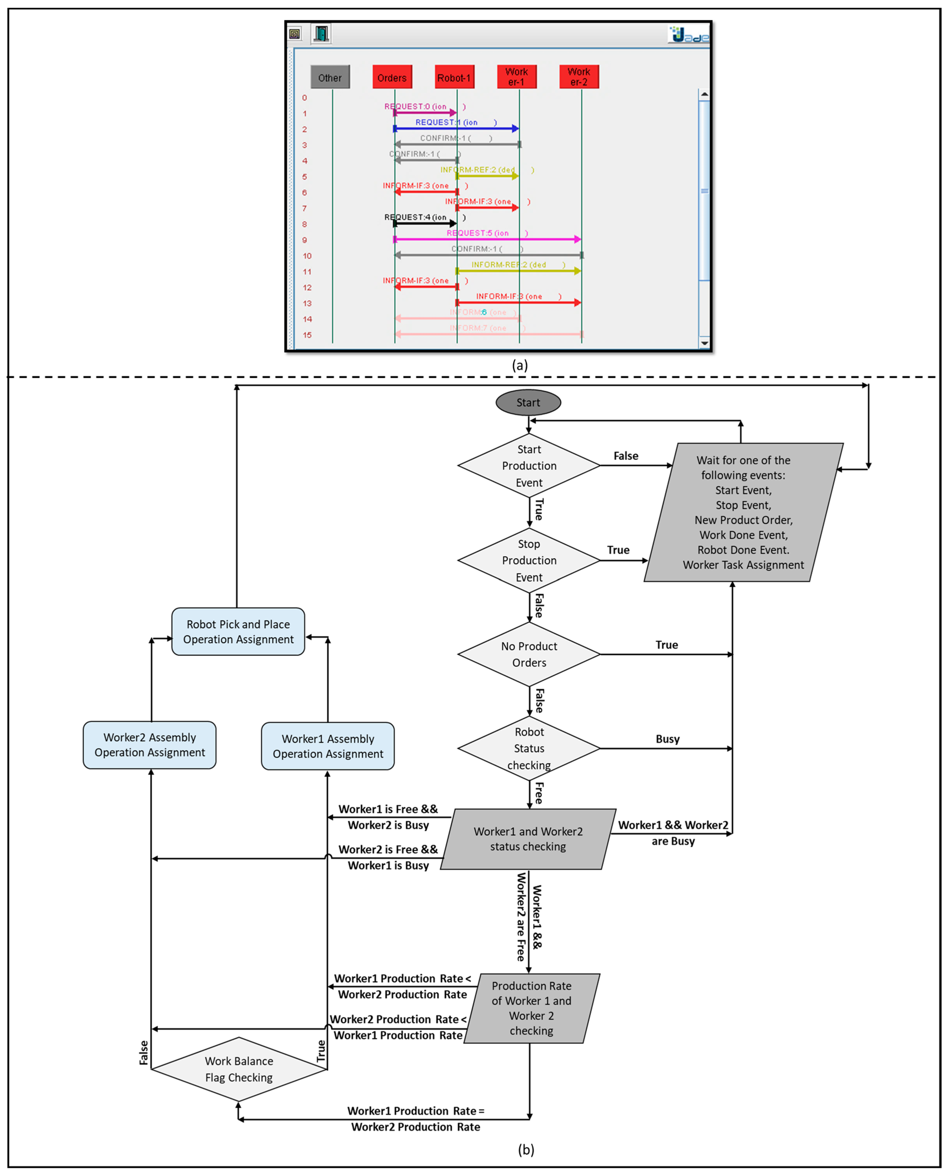
Figure 14a shows JADE interaction scenario between the OH and the ORHs (i.e., worker-1 agent, worker-2 agent, and robot agent). During this interaction, the manufacturing operations are assigned to the operational resources based on their status. As it can be seen in lines 1, 2, 3, and 4 of Figure 14a, the orders agent sends two REQUEST-messages which are replied by two CONFIRM-messages. The first REQUEST-message assigns a Pump-Pick-And-Place-Operation to the robot agent (the content of this message can be seen in Figure 12c at the left). The second REQUEST-message assigns a Pump-Assembly-Operation to worker-1 agent (the content of this message can be seen in Figure 12d at the left). The reason that the pump-order has been processed first by the orders agent is that it is the first product order at the order list (refer to Figure 10e). In line 5 of Figure 14a, the robot agent sends an INFORM-REF-message to worker-1 agent to tell that it placed the first pump unit. Then, the robot agent sends two INFORM-IF-messages to the orders agent and worker-1 agent to tell that it finished handling all the required pump amounts (i.e., three pump units by referring to Figure 10c,d,f). The two INFORM-IF-messages can be seen in lines 6, and 7 of Figure 14a. The same interaction mechanism can be seen in lines 9,10,11,12, and 13 to assign the second pump-manufacturing-order to the worker-2 agent and the robot agent. Lines 14, and 15 of Figure 14a shows the INFORM-messages to express done-signal which is generated from the worker-1 and worker-2 agents to the orders agent.
Reasoning the interaction scenario between the OH and the ORHs is done by the algorithm shown in Figure 14b. This algorithm has been writing in form of Drools rules, however it is much simpler to show it as a flow chart. The algorithm begins by checking that start production condition is true, and stop production is false. If so, the algorithm check if there are pump orders waiting for execution. If not, Drools waits a new event to be received by the OH to start the algorithm again. After checking all the previously mentioned conditions, Drools checks the status of the robot agent to assign the first order at the Pick-And-Place-Operation. IF the robot agent is free, Drools checks the status of both the workers. If worker-1 agent is free and worker-2 agent is busy, Drools assigns the Assembly-Operation to worker-1 agent and starts the algorithm again. If worker-1 agent is busy and worker-2 agent is free, Drools assigns the Assembly-Operation to worker-2 agent and starts the algorithm again. If both the workers are busy, Drools waits a new event to be received by the OH to start the algorithm again. If both the workers are free, Drools checks which worker has assembled more pumps than the other, then the Assembly-Operation will be assigned to the worker who assembled less pumps. This is because the algorithm tries to obtain the balance in distributing the assembly tasks between the two workers. In case both the workers are free and they have been equally assembled the same amount of pumps. Drools assigns to one of them randomly only the first time this case happens. Then, the next time the case happens, Drools assigns to the other worker. After that, Drools keeps switching between the two workers every time this case happens.
6. Discussion, Conclusions, and Future Work
During this article we stated a novel topic of research which is the agile manufacturing in worker–cobot cooperative workcell. The article addressed three related steps to fulfil the research topic. There is no doubt that the first step of establishing an agile cooperative manufacturing is to agree about a common language which can represent the shared environment between the worker and the cobot including themselves. The second step is to exchange this knowledge in a form which is understandable by the human worker and the industrial cobot. The final step is to understand and reason this shared language in order to adapt the overall status of the cooperative workcell with the production demands. Therefore, obtaining the agile manufacturing purpose.
From those mentioned steps, the solution approach was constructed. The proposed solution approach combined three different methodologies, the first methodology is the HCA which guaranteed the autonomy of the cooperative manufacturing system, and moreover the HCA categorized the different entities within the cooperative manufacturing system and defined the responsibilities of every entity. The second methodology is the autonomous agent communication via ontologies. This methodology was not only used to implement the HCA, but also to represent and exchange the knowledge among the different entities of the HCA. Three categories of agent ontology has been used to achieve that purpose. The agent descriptive ontology (i.e., the terms) were used to represent the various objects and entities within the system. The agent structural ontology (i.e., the predicates) were used to indicate the relations between the entities of the HCA for better understanding of the shared domain. The agent administrative ontology (i.e., the actions) were used to express the operations and the routines which can be done by the entities of the HCA. By the last three mentioned ontologies, the holons of the cooperative manufacturing system were completely capable of perceiving themselves and the surrounding. The third methodology which has been used to reason the perceived information is the rule-based system. Some holons of the proposed HCA solution encapsulated a BRMS to create a set of rules which were necessary to process and comprehend the exchanged information and the production requirements.
Combing the HCA, the autonomous agent communication via ontologies, and the BRMS gave the cooperative system the ability to take a collective decision, therefore it can continuously adapt to the required customization in the cooperative manufacturing system. A case-study was shown to demonstrate the viability of the solution approach. In the case-study two customized pumps where introduce to a cooperative workcell which contains two workers in cooperation with one cobot. The task of the workers were to assembly the customized order. While the task of the cobot was to handle the right amount of the pump features to the workers based on their status. The case-study illustrated in detail the idea of using the agent ontology to represent and share the common domain information. The BRMS has been used to infer the required information to manufacture the customer orders. Also, the BRMS was not only able to monitor the status of the operational resources (i.e., the workers and the cobot) to assign the task. But also it was able to follow the productivity of every worker in order to solve some situations such as a worker job assignment in case both the workers are free. Furthermore, the BRMS was very successfully to solve more complicated situations were the two workers are free and have the same productivity.
Even the case-study did not involve a lot of operational resources. It illustrated the concept of the solution approach to achieve the agile manufacturing in worker–cobot cooperative workcell. This solution approach can be scaled over more operational resources and extended all over the shop floor, which is going to be a part of our future research. Moreover, it is so important to avoid the confusion between the HCA and the agent technology. As the HCA is a conceptual approach while agent technology is a tool of implementation. Other technology like industrial web service can used as well to implement be future research. Finally, the future work will implement the solution concept over a real cobot hardware.
Acknowledgments
This research has been supported by the German Federal State of Mecklenburg-Western Pomerania and the European Social Fund under grant ESF/IV-BM-B35-0006/12 and by grants from University of Rostock and Fraunhofer IGD.
Author Contributions
Ahmed R. Sadik conceived the implementation and the analysis of the case study and studied the interaction; Bodo Urban conceived the research concept and the problem statement.
Conflicts of Interest
The authors declare that there is no conflict of interest.
References
- Singh, B.; Sellappan, N.; Kumaradhas, P. Evolution of Industrial Robots and Their Applications. Int. J. Emerg. Technol. Adv. Eng. 2013, 3, 763–768. [Google Scholar]
- Shimon, Y. Handbook of Industrial Robotics; Wiley: New York, NY, USA, 1999; ISBN 0-471-17783-0. [Google Scholar]
- Kutta, A. Robotics; I.K. International Publishing House (Penguin Group): New Delhi, India, 2007; ISBN 978-81-89866-38-9. [Google Scholar]
- Krüger, J.; Lien, T.K.; Verl, A. Cooperation of human and machines in assembly lines. CIRP Ann.-Manuf. Technol. 2009, 58, 628–646. [Google Scholar] [CrossRef]
- Morioka, M.; Sakakibara, S. A new cell production assembly system with human–robot cooperation. CIRP Ann.-Manuf. Technol. 2010, 59, 9–12. [Google Scholar] [CrossRef]
- Heyer, C. Human-robot interaction and future industrial robotics applications. In Proceedings of the 2010 IEEE/RSJ International Conference on Intelligent Robots and Systems (IROS), Taipei, Taiwan, 18–22 October 2010; pp. 4749–4754. [Google Scholar]
- Makris, S.; Karagiannis, P.; Koukas, S.; Matthaiakis, A.S. Augmented reality system for operator support in human–robot collaborative assembly. CIRP Ann.-Manuf. Technol. 2016, 65, 61–64. [Google Scholar] [CrossRef]
- Lasota, A.; Rossano, F.; Shah, A. Safe Close-Proximity Human-Robot Interaction with Standard Industrial Robots. In Proceedings of the IEEE International Conference on Automation Science and Engineering (CASE), Taipei, Taiwan, 18–22 August 2014. [Google Scholar]
- Lasota, A.; Fong, T.; Shah, A. A Survey of Methods for Safe Human-Robot Interaction. Found. Trends Robot. 2017, 5, 261–349. [Google Scholar] [CrossRef]
- Meziane, R.; Otis, M.; Ezzaidi, H. Human-robot collaboration while sharing production activities in dynamic environment: SPADER system. Robot. Comput.-Integr. Manuf. 2017, 48, 243–253. [Google Scholar] [CrossRef]
- Sadik, A.; Bodo, U.; Adel, O. Using Hand Gestures to Interact with an Industrial Robot in a Cooperative Flexible Manufacturing Scenario. In Proceedings of the 3rd International Conference on Mechatronics and Robotics Engineering, Paris, France, 8–12 February 2017; pp. 11–16. [Google Scholar]
- Gleeson, B.; MacLean, K.; Haddadi, A.; Croft, E.; Alcazar, J. Gestures for industry Intuitive human-robot communication from human observation. In Proceedings of the 8th ACM/IEEE International Conference on Human-Robot Interaction (HRI), Tokyo, Japan, 3–6 March 2013. [Google Scholar]
- Sadik, A.; Bodo, U. Combining Adaptive Holonic Control and ISA-95 Architectures to Self-Organize the Interaction in a Worker-Industrial Robot Cooperative Workcell. Future Internet 2017, 9, 35. [Google Scholar] [CrossRef]
- Sadik, A.; Bodo, U. A Novel Implementation Approach for Resource Holons in Reconfigurable Product Manufacturing Cell. In Proceedings of the 13th International Conference on Informatics in Control, Automation and Robotics (ICINCO-2016), Lisbon, Portugal, 29–31 July 2016; pp. 130–139. [Google Scholar]
- Sadik, A.; Bodo, U. Applying the PROSA Reference Architecture to Enable the Interaction between the Worker and the Industrial Robot—Case Study: One Worker Interaction with a Dual-Arm Industrial Robot. In Proceedings of the 9th International Conference on Agents and Artificial Intelligence (ICAART-2017), Porto, Portugal, 24–26 February 2017; pp. 190–199. [Google Scholar]
- Smirnov, A.; Kashevnik, A.; Mikhailov, S.; Mironov, M.; Mikhail, P. Ontology-based collaboration in multi-robot system: Approach and case study. In Proceedings of the 11th System of Systems Engineering Conference (SoSE), Kongsberg, Norway, 12–16 June 2016. [Google Scholar]
- Sadik, A.; Bodo, U. A Holonic Control System Design for a Human & Industrial Robot Cooperative Workcell. In Proceedings of the 2016 International Conference on Autonomous Robot Systems and Competitions (ICARSC), Bragança, Portugal, 4–6 May 2016; pp. 118–123. [Google Scholar]
- Müller, R.; Vette, M.; Mailahn, O. Process-oriented Task Assignment for Assembly Processes with Human-robot Interaction. Proc. CIRP 2016, 4, 210–215. [Google Scholar] [CrossRef]
- Bikas, C.; Argyrou, A.; Pintzos, G.; Giannoulis, C.; Sipsas, K. An automated assembly process planning system. Proc. CIRP 2016, 44, 222–227. [Google Scholar] [CrossRef]
- Sadik, A.; Bodo, U. Flow Shop Scheduling Problem and Solution in Cooperative Robotics—Case-Study: One Cobot in Cooperation with One Worker. Future Internet 2017, 9, 48. [Google Scholar] [CrossRef]
- Jennings, N.; Wooldridge, M. Agent Technology, 1st ed.; Springer: Berlin, Germany, 1998; pp. 3–28. [Google Scholar]
- Shen, W.; Hao, Q.; Yoon, H.; Norrie, D. Applications of agent-based systems in intelligent manufacturing: An updated review. Adv. Eng. Inform. 2006, 20, 415–431. [Google Scholar] [CrossRef]
- Jade Site. Available online: http://jade.tilab.com/ (accessed on 8 January 2017).
- FIPA Site. Available online: http://www.fipa.org/ (accessed on 1 February 2017).
- Bellifemine, F.; Caire, G.; Greenwood, D. Developing Multi-Agent Systems with JADE, 1st ed.; Wiley: Chichester, UK, 2008. [Google Scholar]
- Ordóñez, A.; Eraso, L.; Ordóñez, H.; Merchan, L. Comparing Drools and Ontology Reasoning Approaches for Automated Monitoring in Telecommunication Processes. Proc. Comput. Sci. 2016, 95, 353–360. [Google Scholar] [CrossRef]
- Al-Ajlan, A. The Comparison between Forward and Backward Chaining. Int. J. Mach. Learn. Comput. 2015, 5, 106–113. [Google Scholar] [CrossRef]
- Drools Guide. Available online: https://docs.jboss.org/drools/release/5.2.0.CR1/drools-expert-docs/html_single/ (accessed on 18 April 2017).
- Sottara, D.; Mello, P.; Proctor, M. A configurable rete-oo engine for reasoning with different types of imperfect information. IEEE Trans. Knowl. Data Eng. 2010, 22, 1535–1548. [Google Scholar] [CrossRef]
- Leitão, P.; Restivo, F. Implementation of a Holonic Control System in a Flexible Manufacturing System. IEEE Trans. Syst. Man Cybern. Part C Appl. Rev. 2008, 38, 699–709. [Google Scholar] [CrossRef]
- Botti, V.; Giret, A. Holonic Manufacturing Systems. In ANEMONA—A Multi-Agent Methodology for Holonic Manufacturing Systems, 1st ed.; Springer: London, UK, 2008; pp. 7–20. [Google Scholar]
- Babiceanu, R.; Chen, F. Development and Applications of Holonic Manufacturing Systems: A Survey. J. Intell. Manuf. 2006, 17, 111–131. [Google Scholar] [CrossRef]
- Van Brussel, H.; Wyns, J.; Valckenaers, P.; Bongaerts, L.; Peeters, P. Reference architecture for holonic manufacturing systems: PROSA. Comput. Ind. 1998, 37, 255–274. [Google Scholar] [CrossRef]
- Black, G.; Vyatkin, V. Intelligent Component-Based Automation of Baggage Handling Systems with IEC 61499. IEEE Trans. Autom. Sci. Eng. 2008, 7, 699–709. [Google Scholar] [CrossRef]
- Balakirsky, S. Ontology based action planning and verification for agile manufacturing. Robot. Comput.-Integr. Manuf. 2015, 33, 21–28. [Google Scholar] [CrossRef]
- Fiorini, S.R.; Carbonera, J.L.; Gonçalves, P.; Jorge, V.A.; Rey, V.F.; Haidegger, T.; Abel, M.; Redfield, S.A.; Balakirsky, S.; Ragavan, V.; et al. Extensions to the core ontology for robotics and automation. Robot. Comput.-Integr. Manuf. 2015, 33, 3–11. [Google Scholar] [CrossRef]
- Rodrigues, N. Development of an Ontology for a Multi-Agent System Controlling a Production Line. MSc Thesis, Instituto Politécnico de Bragança, Bragança, Portugal, 2012. [Google Scholar]
- Freitas, F.L.; Bittencourt, G. An ontology-based architecture for cooperative information agents. Int. Jt. Conf. Artif. Intell. 2003, 18, 37–42. [Google Scholar]
- Takeda, H.; Iwata, K.; Takaai, M.; Sawada, A.; Nishida, T. An ontology-based cooperative environment for real-world agents. Proc. Second Int. Conf. Multiagent Syst. 1996, 353, 360. [Google Scholar]
- Neches, R.; Fikes, R.; Finin, T.; Gruber, T.; Patil, R.; Senator, T.; Swartout, W. Enabling Technology for Knowledge Sharing. Al Mag. 1991, 12, 36–56. [Google Scholar]
- Gruber, T. Toward principles for the design of ontologies used for knowledge sharing. Int. J. Hum.-Comput. Stud. 1995, 43, 907–928. [Google Scholar] [CrossRef]
- Wang, H.; Gibbins, N.; Payne, T.; Redavid, D. A formal model of the Semantic Web Service Ontology (WSMO). Inf. Syst. 2012, 37, 33–60. [Google Scholar] [CrossRef]
- Fensel, D. Ontology-based knowledge management. Robot. Comput.-Integr. Manuf. 2002, 35, 56–59. [Google Scholar] [CrossRef]
- Lai, L. A knowledge engineering approach to knowledge management. Inf. Sci. 2007, 117, 4072–4094. [Google Scholar] [CrossRef]
Figure 1.
Evolution of Industrial Robotics.

Figure 2.
Challenges in Cooperative Manufacturing.
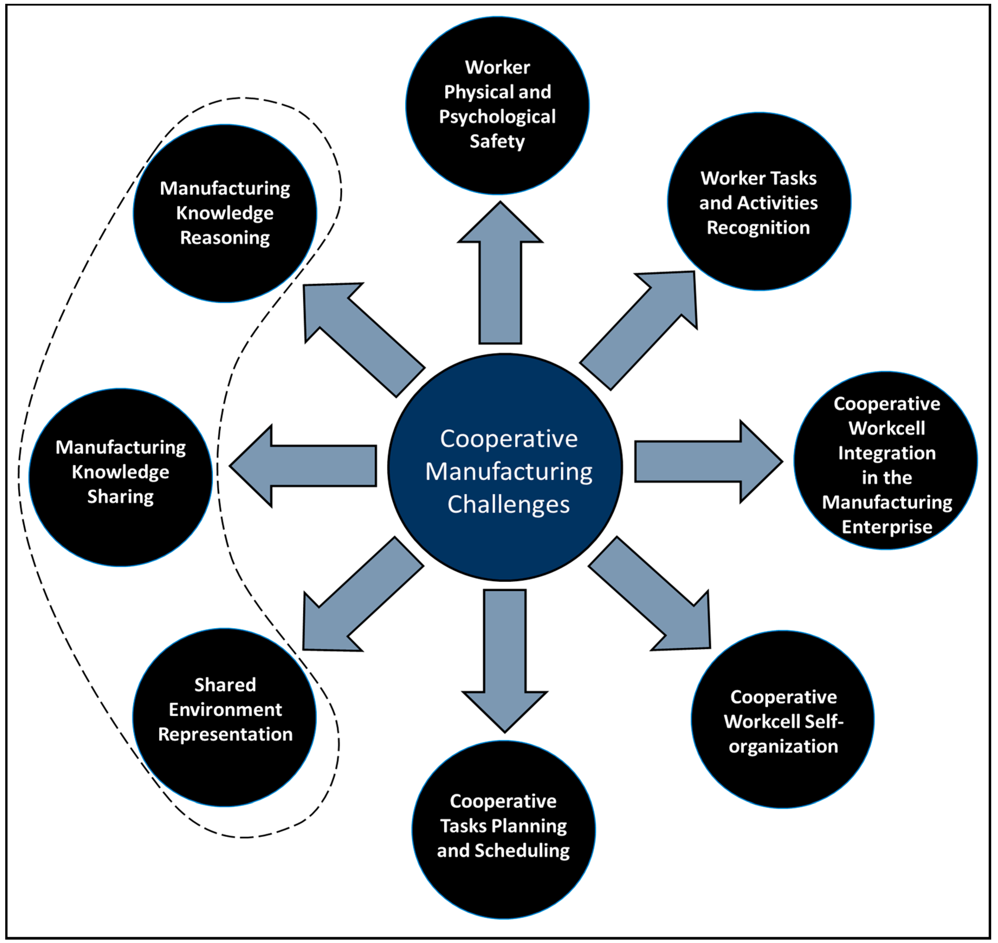
Figure 3.
(a) Java Agent Development (JADE); (b) Ontology-Based Agent Communication Language (ACL)-Message Exchange.
Figure 3.
(a) Java Agent Development (JADE); (b) Ontology-Based Agent Communication Language (ACL)-Message Exchange.

Figure 4.
Rule-based System (a) Components and Operating Mechanism; (b) An Example.
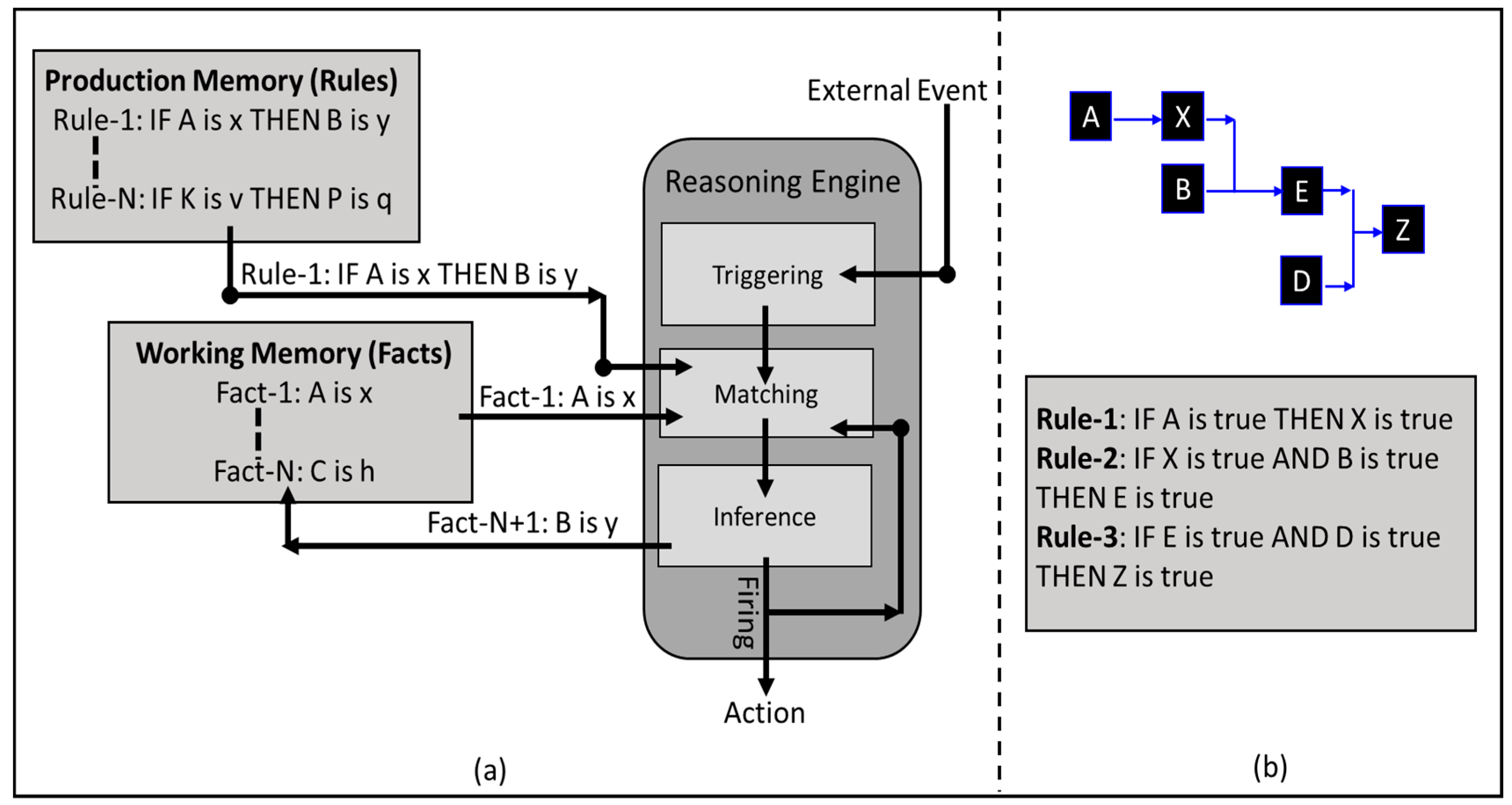
Figure 5.
(a) Forward Reasoning—an Example; (() Backward Reasoning—an Example.

Figure 6.
Drools Pattern Matching Mechanism.

Figure 7.
(a) Holon Generic Anatomy; (b) Product-Resource-Order-Staff-Architecture (PROSA) Model Holarchy.
Figure 7.
(a) Holon Generic Anatomy; (b) Product-Resource-Order-Staff-Architecture (PROSA) Model Holarchy.
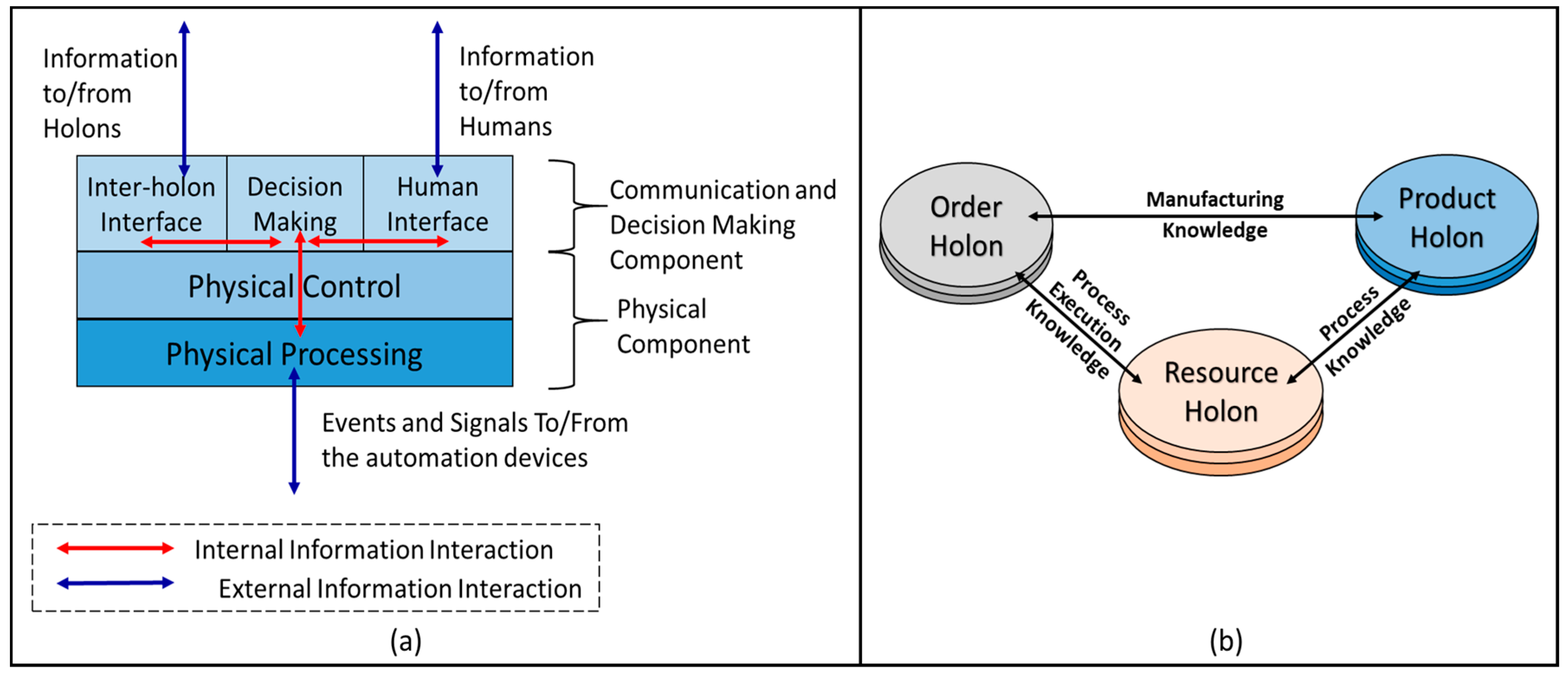
Figure 8.
Proposed Holonic Control Architecture Model.
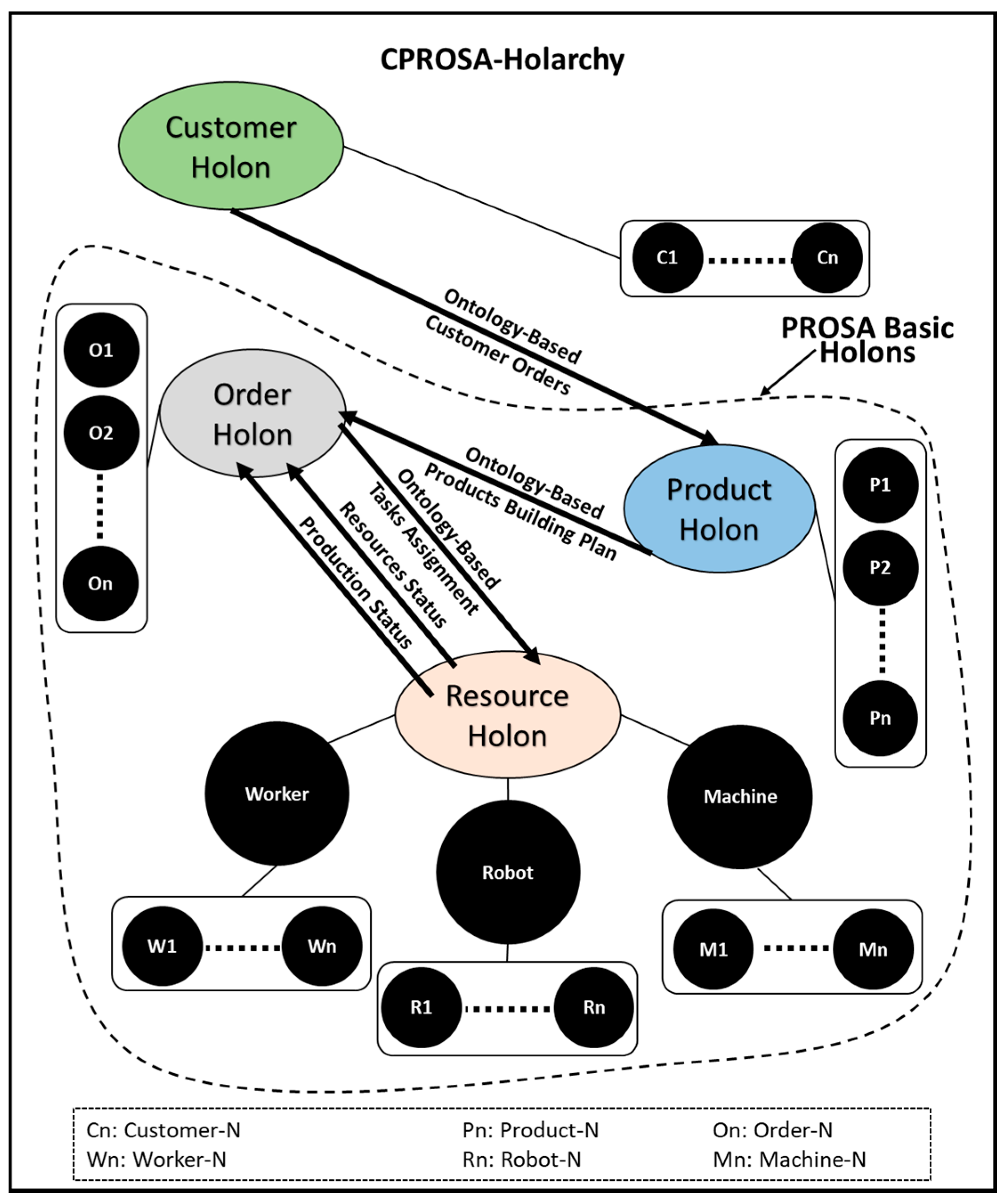
Figure 9.
Proposed Holon Model.

Figure 10.
(a) Case-Study Schematic; (b) JADE Multi-Agent System; (c) Customer Holon Interface; (d) Products Holons Interface; (e) Order Holon Interface; (f) Operation Resources Holons Interface.
Figure 10.
(a) Case-Study Schematic; (b) JADE Multi-Agent System; (c) Customer Holon Interface; (d) Products Holons Interface; (e) Order Holon Interface; (f) Operation Resources Holons Interface.
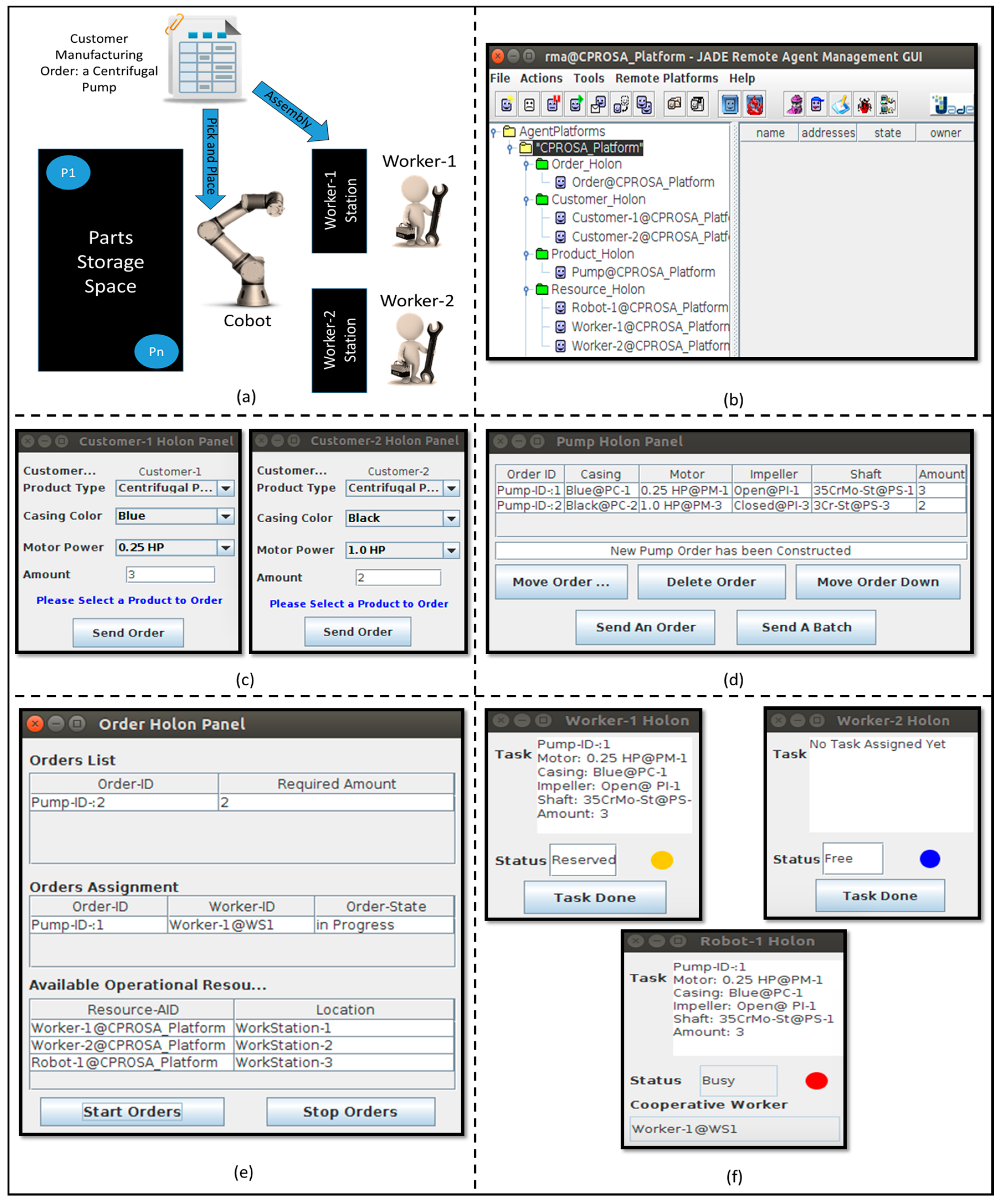
Figure 11.
Case-Study Ontology.

Figure 12.
The Contents of the Ontology-Based ACL-Messages during the Case-Study (a) Building Operations; (b) Manufacturing Operation; (c) Pick and Place Operation; (d) Assembly Operation.
Figure 12.
The Contents of the Ontology-Based ACL-Messages during the Case-Study (a) Building Operations; (b) Manufacturing Operation; (c) Pick and Place Operation; (d) Assembly Operation.

Figure 13.
(a) JADE interaction among the customer holons and the pump holon; (b) Drools reasoning to build a pump details from a customer order; (c) JADE interaction between the pump holon and the order holon.
Figure 13.
(a) JADE interaction among the customer holons and the pump holon; (b) Drools reasoning to build a pump details from a customer order; (c) JADE interaction between the pump holon and the order holon.

Figure 14.
(a) JADE interaction among the order holon and the operational resources holon; (b) Drools algorithm to assign the operations to the operational resources.
Figure 14.
(a) JADE interaction among the order holon and the operational resources holon; (b) Drools algorithm to assign the operations to the operational resources.

© 2017 by the authors. Licensee MDPI, Basel, Switzerland. This article is an open access article distributed under the terms and conditions of the Creative Commons Attribution (CC BY) license (http://creativecommons.org/licenses/by/4.0/).
Share and Cite
MDPI and ACS Style
Sadik, A.R.; Urban, B. An Ontology-Based Approach to Enable Knowledge Representation and Reasoning in Worker–Cobot Agile Manufacturing. Future Internet 2017, 9, 90. https://doi.org/10.3390/fi9040090
AMA Style
Sadik AR, Urban B. An Ontology-Based Approach to Enable Knowledge Representation and Reasoning in Worker–Cobot Agile Manufacturing. Future Internet. 2017; 9(4):90. https://doi.org/10.3390/fi9040090
Chicago/Turabian StyleSadik, Ahmed R., and Bodo Urban. 2017. "An Ontology-Based Approach to Enable Knowledge Representation and Reasoning in Worker–Cobot Agile Manufacturing" Future Internet 9, no. 4: 90. https://doi.org/10.3390/fi9040090
Note that from the first issue of 2016, this journal uses article numbers instead of page numbers. See further details here.