
Research on the Stability Control Strategy of High-Speed Steering Intelligent Vehicle Platooning

College of Automobile and Traffic Engineering, Nanjing Forestry University, Nanjing 210037, China
*
Author to whom correspondence should be addressed.
World Electr. Veh. J. 2024, 15(4), 169; https://doi.org/10.3390/wevj15040169
Submission received: 12 March 2024
/
Revised: 11 April 2024
/
Accepted: 16 April 2024
/
Published: 18 April 2024
(This article belongs to the Special Issue Design Theory, Method and Control of Intelligent and Safe Vehicles)
Abstract
:Based on an investigation of how vehicle structural characteristics and system parameters influence the motion stability of high-speed steering intelligent vehicle platooning, a control strategy for ensuring motion stability is proposed. This strategy is based on a virtual articulated concept and is validated using both characteristic equation analysis and time domain analysis methods. To create a system, any two adjacent front and rear vehicles in the intelligent vehicle platooning are connected using a virtual articulated model constructed through the virtual structure method. A ten-degrees-of-freedom model of the intelligent vehicle platooning system is established, taking into account the nonlinearities of the tire and steering systems, utilizing the principles of the second Lagrange equation theory. The system damping ratio is determined through characteristic equation analysis, and the system’s dynamic critical speed is assessed by examining the relationship between the damping ratio and the motion stability of the intelligent vehicle platooning, serving as an indicator of system stability. By applying sensitivity analysis, control variable analysis, and time domain analysis methods, the influence of vehicle structural characteristics and system parameters on the system’s dynamic critical speed and motion stability under lateral disturbances within the intelligent vehicle platooning is thoroughly investigated, thereby validating the soundness of the proposed control strategy.
1. Introduction
In recent years, the exponential rise in the number of automobiles has brought about pressing concerns regarding resource depletion, environmental degradation, and traffic congestion. To tackle these challenges, intelligent transportation research has shifted its focus towards exploring more sustainable, eco-friendly, and efficient modes of transportation [1,2,3]. Among these advancements, intelligent vehicle platooning (IVP) has garnered significant attention owing to its remarkable benefits. Studies reveal that vehicles within intelligent vehicle platooning leverage communication technologies to regulate real-time acceleration and deceleration, maintaining consistent spacing and velocity, thus forming tight-knit convoys that enhance road safety, alleviate traffic congestion, and reduce fuel consumption [4,5]. Consequently, intelligent vehicle platooning holds substantial practical value and research importance.
The dynamic interaction among vehicles within a platoon presents a formidable obstacle to ensuring stability in the motion of intelligent vehicle platooning. For instance, this includes addressing the security issues of longitudinal vehicle platoons facing denial-of-service attacks and developing resilient, event-triggered model predictive control strategies for adaptive cruise control systems under sensor attacks [6,7]. Presently, investigations into the motion stability of intelligent vehicle platooning primarily concentrate on scrutinizing string stability. Approaches to studying the longitudinal string stability of intelligent vehicle platooning can be broadly classified into three categories: transfer function analysis, Lyapunov function analysis, and characteristic equation analysis.
(1) The transfer function analysis method transforms a time domain system into a frequency domain system through Laplace transformation and evaluates the amplitude of the transfer function. This method primarily examines the frequency response between system input and output variables [8,9]. Widely adopted for analyzing the stability of linear system queues, the transfer function analysis method was utilized by Zhang et al. to study the longitudinal dynamics design of networked cruise vehicles, exploring the effects of various connection structures and communication delays on vehicle platooning. By applying transfer function theory, they established boundary conditions for the string stability [10]. Additionally, Jin et al. investigated the impact of vehicle platooning heterogeneity and driver reaction time, deriving the head-to-tail transfer function by removing intermediate vehicles and analyzing string stability conditions [11]. Building on this, Qin Yan et al. and Qin et al. integrated the throttle control angle of vehicles into their analysis, incorporating speed, acceleration, and communication delay feedback from multiple leading vehicles to construct a platooning model [12,13]. By considering the local leader vehicle’s speed disturbance as the system input and tail speed disturbance as the output, they deduced constraints for the platooning’s motion stability using the transfer function analysis method. Meanwhile, Wang Hao et al. utilized the platooning model to determine the transfer function of disturbance propagation in traffic flow and investigated the stability domain in heterogeneous fleets with varying proportions of networked vehicles [14]. Results indicated that under specific equilibrium speeds and networked car ratio conditions, the system approached asymptotic stability.
While the transfer function analysis method simplifies the intelligent vehicle platooning system into a quantitative mathematical model, its complex mathematical requirements and limited applicability to nonlinear systems are notable drawbacks. Consequently, the application of the Lyapunov analysis method for nonlinear system models is warranted.
(2) The Lyapunov analysis method evaluates the stability of dynamic systems by leveraging Lyapunov stability theory. This approach involves selecting and manipulating Lyapunov functions related to system state variables or errors to assess system stability, typically determining stability by verifying that the Lyapunov function’s rate of change is negative [15]. Yadlapalli et al. and Klinge et al. developed identical structured intelligent vehicle platooning system models. They derived a formula for minimum time progression to guarantee motion stability under initial condition disturbances based on and norm constraints [16,17]. Subsequently, Besselink et al. explored the nonlinear system model established with the vehicle dynamics model and the delay interval strategy, analyzing system queue stability under dual disturbances of initial and external factors by employing Lyapunov functions [18]. Moreover, Feng et al. summarized the methods for assessing the string stability of nonlinear intelligent vehicle platooning systems and highlighted the analysis process of Lyapunov stability for diverse systems [15].
While the Lyapunov analysis method offers notable benefits for analyzing nonlinear systems, its widespread adoption is hindered by the challenges in constructing Lyapunov functions for specific cases. However, the characteristic equation analysis method facilitates the analysis of nonlinear system equations and reduces complexity, making it a more practical choice.
(3) The characteristic equation analysis method linearizes vehicle dynamics equations to establish the interdependence between leading and following vehicles, deriving system equations with characteristic values [19]. Subsequently, it examines the system’s stability conditions based on Lyapunov’s first theorem to determine stability criteria. Zheng et al. employed feedback linearization techniques to create a linearized vehicle dynamics model considering dynamic inertia delays. Using algebraic graph theory and Routh–Hurwitz stability criterion theory, they analyzed the system matrix eigenvalues to assess the impact of three specific information flow topology structures on the string stability and scalability [20,21]. Building on this, Liu et al. investigated a generic information flow topology structure and established necessary and sufficient conditions for the string stability by analyzing the Laplace matrix eigenvalues of the vehicle platooning system [22]. Furthermore, they developed a third-order vehicle platooning dynamics model and formulated a distributed linear control approach based on an equidistant strategy [23]. This design ensured single-vehicle stability, scalability, rapid convergence, and string stability performance by evaluating the system matrix eigenvalues, controller gains, and model parameters across a general information flow structure.
In conclusion, in the domain of intelligent vehicle platooning dynamics, parameter design, extensive comparison, and optimization schemes are prevalent. Yet, these methods typically fall short in scientific rigor, leaving the reasons for improved queue driving stability through optimized parameter matching schemes unclear. Concurrently, research on the lateral stability control of intelligent fleets and the analysis of system parameters’ impact on overall stability is limited. Thus, utilizing the characteristic equation analysis method, this paper investigates the motion stability of high-speed steering in intelligent platoons and endeavors to provide a more systematic approach. Firstly, the study accounts for the nonlinearity of tire and steering characteristics during high-speed driving. A virtual articulated model is developed via the virtual structure method, and the dynamic model of the nonlinear system is constructed using the second Lagrange equation analysis method. Next, by analyzing the interplay between the structural features of intelligent vehicle platooning and system parameters based on virtual articulation, a control strategy aimed at mitigating the motion stability in high-speed turns is presented. Lastly, the application of pertinent nonlinear equations and time domain analysis methods is employed to validate the suggested control approach for the intelligent vehicle platooning system, offering a scientific rationale for platooning stability control strategies in high-speed turning scenarios for intelligent vehicle platooning.
The rest of this paper is organized as follows. Section 2 discusses the modeling process of the intelligent vehicle platooning system. Section 3 presents the control strategy for maintaining the system’s dynamic stability. Section 4 calculates the system’s critical speed for dynamic stability and examines the impact of system parameters on this stability. Section 5 analyzes how initial disturbances affect the system’s lateral stability. Finally, Section 6 summarizes the study’s findings and proposes directions for future research.
2. Intelligent Vehicle Platooning System Model
This paper constructs an intelligent vehicle platooning system dynamics model based on virtual articulation based on analogies with the actual semi-trailer system structure. Firstly, a single-vehicle model is established, including a nonlinear “magic formula” tire model and a nonlinear steering system model; secondly, a virtual articulated model is established; and finally, the intelligent vehicle platooning system model is constructed by combining the virtual articulated model with the method that analyzes the second Lagrange equation.
2.1. Single-Vehicle Model and Virtual Articulated Model
In the actual semi-trailer system structure, the tractor pulls the trailer through a rigid linkage to enable the trailer to follow the tractor in lateral turns and during longitudinal acceleration and deceleration periods. In an intelligent vehicle platoon, considering that the following vehicle needs to maintain the desired spacing and speed with the leading vehicle, with the position, velocity, and acceleration of the leading vehicle as the stimuli, the following vehicle autonomously maintains the convoy with the leading vehicle. Therefore, in an intelligent vehicle platoon, the continuous leading and following vehicles are analogized with regards to the actual semi-trailer structure of the tractor and trailer. By introducing the concept of “virtual force” through the virtual structure method, the leading vehicle “pulls” the following vehicle in motion.
As shown in Figure 1, any two vehicles in the convoy are connected by a virtual articulated point P, forming a virtual articulated intelligent vehicle platooning system model. The vehicles in the system model all adopt a front wheel gear rack steering structure, assuming that the left and right wheel structures are symmetrical in force, and the steering wheel remains fixed with a steady response while ignoring the effects of suspension, aerodynamics, and wheel load transfer.
The subscripts and represent the front and rear axles of the vehicle, respectively; the subscripts and represent the leading and following vehicles in the virtual articulated intelligent vehicle platooning system; and represent the longitudinal and lateral tire forces, e.g., represents the lateral force acting on the front axle of the following vehicle; represent the distances from the front axle to the center of mass, from the rear axle to the center of mass, and from the center of mass to the virtual articulated point; and represents the intersection of the longitudinal axes of the leading and following vehicles.
In a single-vehicle model, the tire model is an important component. Tires provide the necessary forces for acceleration, deceleration, and steering by contacting the road surface, and when the vehicle is in high-speed steering mode, the contact force between the tire and the ground shows strong nonlinear characteristics due to the tire characteristics approaching or being in saturation. Therefore, this paper adopts the nonlinear magic formula tire model to calculate the longitudinal and lateral forces acting on the system tires.
Here, are the axle top factor, curve shape factor, stiffness factor, and curve curvature factor, respectively; are the horizontal and vertical drift values of the curve; is the longitudinal slip rate of the wheel; and is the lateral deflection angle of the wheel. The parameter values are shown in Table 1.
The expression for the lateral inclination angle of the front and rear axles is as follows:
where is the wheel turning angle, is the vehicle transverse angular velocity, is the transverse velocity at the center of mass of the vehicle, is the angle between the front and rear axle lines, and .
The expression for the longitudinal slip rate of a tire is as follows:
where is the tire radius and is the tire rotation angular velocity.
The force exerted on the tires is decomposed into the vehicle coordinate system, and the resulting total forces along the and axes of the wheels are calculated as follows:
When the system becomes unstable, the pressure on the main axle of the wheel changes drastically, leading to a continuous change in the friction force on the main axle of the wheel. Therefore, in order to ensure the accuracy of the model, this article considers the effect of dry friction force on the system. The dry friction force is calculated using the Coulomb dry friction model.
To simplify the calculation, the sign function is Fourier-transformed and then linearized to obtain the expression.
where is the dry friction force, is the dry friction torque, is the friction factor, is the positive pressure at the main pin, and is the effective length of the steering knuckle arm.
The virtual articulated point connects the front and rear vehicles, as shown in Figure 2. This point experiences the ‘traction force’ from the front vehicle and the ‘drag force’ from the rear vehicle. The system achieves balance when these forces are equal. In this study, we define ‘traction force’ and ‘drag force’ as virtual forces, which are further divided into lateral and longitudinal forces acting on the front and rear vehicles. In the diagram, the subscripts and denote the vehicle’s ordinate and abscissa, respectively. For instance, represents the lateral virtual drag force acting on the following vehicle.
Relationship between front and rear vehicle virtual forces.
When the intelligent vehicle platooning is cruising steadily, the lateral velocity at the virtual point satisfies the following expression.
2.2. Intelligent Vehicle Platooning State Space Model
Based on a single-vehicle model and a virtual articulated model, this paper uses the method that analyzes the second Lagrange equation to establish a ten-degrees-of-freedom virtual articulated intelligent vehicle platooning system model. The ten-degrees-of-freedom model provides steering column rotation, rack and pinion motion, wheel rotation, and both lateral and yaw motions of the vehicle.
Due to the complex spatial structure and force conditions of the steering system, in order to facilitate the analysis of the kinetic energy, potential energy, and dissipated energy in the system model, as well as to identify the influence of the steering system on the motion stability of the system, this paper establishes a three-degrees-of-freedom steering system model and proposes an equivalent method to equivalently represent the deformation of the steering tie rod and the gear rack separately to the main pin and the steering column, where and are equivalent coefficients [24,25].
The intelligent vehicle platooning system model is established using the second Lagrange equation analysis theory. Firstly, the kinetic energy, potential energy, and dissipated energy in the system model are analyzed. The system kinetic energy includes steering column torsional kinetic energy, rack displacement kinetic energy, wheel swing kinetic energy, vehicle lateral motion kinetic energy, and yaw motion kinetic energy, which can be specifically expressed as the following:
where is the mass of the vehicle; is the moment of inertia of the vehicle; and are the moment of inertia of the steering column, the equivalent moment of inertia of the rack to the kingpin, and the moment of inertia of the front wheel around the kingpin.
The system potential energy consists of steering column variable situation energy, gear rack meshing variable situation energy, and rod variable situation energy between the rack and kingpin, which can be expressed as the following:
where are the torsional stiffness of the steering wheel, the equivalent stiffness of the gear and rack meshing, and the equivalent deformation stiffness of the steering tie rod, respectively.
The system dissipation energy consists of steering column deformation, gear rack meshing deformation, rod deformation between the rack and kingpin, and the energy consumed by the front wheel swinging around the kingpin, which can be specifically expressed as the following:
where are the torsional damping of the steering wheel, the equivalent damping of the rack and pinion meshing, the equivalent damping of the deformation of the steering tie rod, and the rotational damping of the front wheel around the kingpin.
By combining Equations (10)–(12) and using the second Lagrange equation and the Newtonian kinematic equation, the system of dynamic equations can be derived. These equations include the rotational motion of the steering wheel around the main pin, the rotational motion of the rack translated to the main pin, the lateral motion, and the yaw motion.
(1) The rotational motion of the steering wheel around the main pin
(2) The rotational motion of the rack translated to the main pin
(3) The lateral motion
(4) The yaw motion
where are the generalized coordinates of the system and is the generalized force corresponding to the generalized coordinate.
The state variables and system input of the system are then defined.
By combining Equations (8), (9), and (13)–(16), we can derive the system’s nonlinear dynamic differential equations.
where and are system matrices, and contains the nonlinear part of the system state equation and the input part of the system.
3. Motion Stability Control Strategy
This paper proposes a high-speed steering stability control strategy for signal-free intersection for intelligent vehicle platooning considering system dynamics models and compact driving. The motion stability performance of intelligent vehicle platooning depends on the characteristics of the fleets themselves and is also influenced by external disturbances. For intelligent vehicle platooning at high speeds, external disturbances include disturbances such as rough road surfaces and crosswinds.
In the study of the high-speed steering stability of intelligent vehicle platooning, as the system exhibits strong nonlinear characteristics, different stability states will be demonstrated under different curved road conditions. Therefore, it is necessary to determine the steering wheel angle of the front vehicle.
Figure 3 shows that as the system’s driving speed increases, the stable region of the system decreases, the unstable region increases, and the influence of the critical steering input angle on the system’s driving speed becomes smoother under high-speed conditions. Therefore, to ensure the motion stability of the system, it is necessary to rely on the constraints of the vehicle’s own characteristics on the system, mainly achieved through certain steering system parameters, mass, and rotational inertia to achieve vehicle stability. From Figure 4, it can be seen that the overall vehicle mass and yaw rotational inertia are negatively correlated with the system’s motion stability, the steering system rotational inertia is positively correlated with the system’s motion stability, and the sensitivity of the overall vehicle mass to the system’s stability is the highest. When the vehicle’s own characteristics are not sufficient to improve the system’s motion stability, system stability can be further enhanced by coupling between vehicles.
Based on the above analysis, a control strategy for the motion stability of intelligent vehicle platooning based on virtual articulation is proposed, as shown in Figure 5. For the design of the high-speed steering motion stability of intelligent vehicle platooning, it is essential to ensure that the intelligent vehicle platooning system has sufficient stable driving capability first; secondly, when the stability of the intelligent vehicle platooning system is insufficient, the characteristics of the vehicle itself can be considered to improve stability; and finally, the coupling relationship between vehicles in the intelligent vehicle platooning system can be considered to further enhance the system stability performance.
4. Motion Stability Analysis
To validate the control strategy for the stability of intelligent vehicle platooning, analyzing the system’s movement stability is essential. A key indicator for assessing system stability is the critical vehicle speed in the system dynamics. In this study, Formula (18) is adapted for a general system, with the state equation represented as follows:
Here, is the state vector, is a vector function, , is the parameter vector, and is the input vector of the system.
By solving the characteristic equation of the system matrix, the system’s characteristic roots can be obtained, as shown below.
The system damping ratio is defined as follows:
Here, and represent the real and imaginary parts of the characteristic roots of the vehicle system characteristic equation. When the system damping ratio , the system is in a critical stable state; when , the system is in a stable state; and under other conditions, the system is in an unstable state. Therefore, according to the variation in the system damping ratio curve, as defined, the dynamic critical speed of the system can be determined.
According to the theory of the characteristic equation analysis method, this paper linearizes the complex nonlinear system dynamic equations near the equilibrium point using Taylor series expansion. Firstly, by taking the speed of the front vehicle as the control variable of the system and keeping the front wheel steering angle of the front vehicle constant, the equilibrium points corresponding to the system under different speeds are calculated as follows:
The system is Taylor-expanded near the equilibrium point, and, after neglecting higher-order terms, the following is obtained:
In the formula, the first derivative is expanded as follows:
The internal stability of vehicle platooning near the equilibrium point depends on the eigenvalues of the coefficient matrix’s characteristic equation. The characteristic equation is as follows:
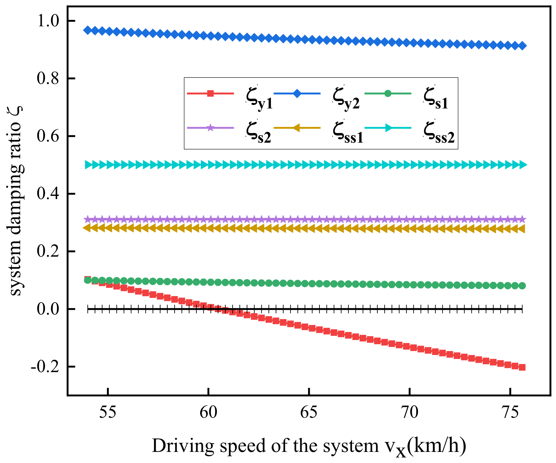
According to the theory mentioned above, the dynamic response characteristics at the equilibrium point can be analyzed by adopting the system damping ratio. The vehicle platooning system established in this paper has a total of six pairs of conjugate complex roots. Therefore, six damping characteristic curves can be plotted, including the steering damping characteristics and the lateral stability damping characteristics of the system.
Utilizing the characteristic equation analysis method for nonlinear systems, the system damping ratio (ζ) is defined. A system damping ratio (ζ) of 0 indicates a critical stable state; a ratio between 0 and 1 denotes stability; and any other values signify instability. This approach allows the dynamic critical speed of the system to be determined based on changes in the damping ratio curve. Figure 6 shows the variation in the six damping ratio characteristic curves as the vehicle speed gradually increases from 54 km/h to 75.6 km/h. The figure shows that as the system speed increases, the steering damping characteristic curves , , , and remain almost unchanged, indicating that the steering characteristics do not change with the increase in system speed, only related to the inherent parameters of the steering system itself, such as stiffness, damping, etc. However, the lateral stability damping characteristic curves and gradually change from positive damping to negative damping as the system speed increases, indicating that the system is critically stable at this time, and the critical speed is approximately 60.48 km/h.
Based on the dynamic critical vehicle speed of the system, the maximum stable speed at which the system can operate under different conditions is determined. Additionally, when the intelligent vehicle platooning makes turns, the parameters between the front and rear vehicles, the rear wheel steering angle, the following distance, and the distance from the virtual articulated point to the front axle of the lead vehicle collectively affect the dynamic stability of the system. Therefore, a control variable analysis method is used to study the effects of the rear vehicle actively steering, adjusting the following distance, and positioning the virtual articulated e-point on the dynamic critical vehicle speed of the intelligent vehicle platooning system.
Figure 7 illustrates the influence of changes in the rear wheel steering angle, the following distance, and the virtual articulated point on the system’s critical vehicle speed. Figure 7a shows the impact of the front and rear vehicle distance on the system’s dynamic critical vehicle speed. It can be observed from the graph that with an increase in the following distance, the system’s dynamic critical vehicle speed shows an approximate linear growth, enhancing the system’s disturbance rejection capability. Figure 7b depicts the effect of the virtual articulated point distance from the front axle of the lead vehicle on the system’s dynamic critical vehicle speed. It is evident from the graph that as the hinge point moves away from the front vehicle, the system’s dynamic critical vehicle speed first increases then decreases, reaching a peak when the distance from the front of the vehicle is 1.5 m. Figure 7c illustrates the impact of rear vehicle active steering within a certain range under different following distances on the system’s dynamic critical vehicle speed, with the front vehicle’s front wheel steering angle set at 20°. Considering the compactness of the intelligent vehicle fleet during operation, the range for the rear vehicle’s front wheel steering angle is chosen to be in the range of 11° to 30°. It can be seen from the graph that with an increase in , the system’s dynamic critical vehicle speed slowly increases to a peak and then gradually decreases, and, as the following distance increases, the peak shifts slowly to the right. Therefore, during turns in the intelligent vehicle platooning, a certain front and rear vehicle distance can be selected based on road conditions, along with slight active steering, to control the fleet for stable high-speed operation. Thus, the accuracy of the proposed control strategy can be demonstrated.
5. Simulation Analysis
Intelligent vehicle platooning frequently encounters lateral disturbances, such as wind, while driving. To assess the system’s stability under lateral disturbances near its dynamic critical speed, MATLAB- - R2021b simulation software is utilized to analyze the platoon system model, focusing on the yaw motion response at various speeds.
Figure 8 shows the initial response curve of the front vehicle’s yaw rate under different driving speeds. The initial states are represented by and . When the system’s driving speed is 54 km/h, the front vehicle’s yaw rate oscillates and converges to 0 under the initial lateral velocity disturbance. The oscillation amplitude increases as the initial lateral velocity disturbance increases, but the convergence speed decreases. When is 60.48 km/h, the front vehicle’s yaw rate continues to oscillate and increases when the initial lateral velocity disturbance is increased to approximately 1°/s and 6°/s, respectively. This indicates that the system is in a critical stable state. When the system is subject to significant external disturbances, the amplitude of the yaw rate increases rapidly, leading to system instability. When is 75 km/h, the front vehicle’s yaw rate diverges over time under the initial lateral velocity disturbance, and the divergence amplitude increases with an increasing initial lateral velocity disturbance. When subjected to a lateral disturbance of 0.5 m/s, the system’s amplitude rapidly increases after 10 s and reaches around 20°/s at 19 s, indicating an unstable state. On the other hand, when subjected to a lateral disturbance of 0.1 m/s, the divergence speed is slower, but the yaw rate continues to increase over time until instability is reached.
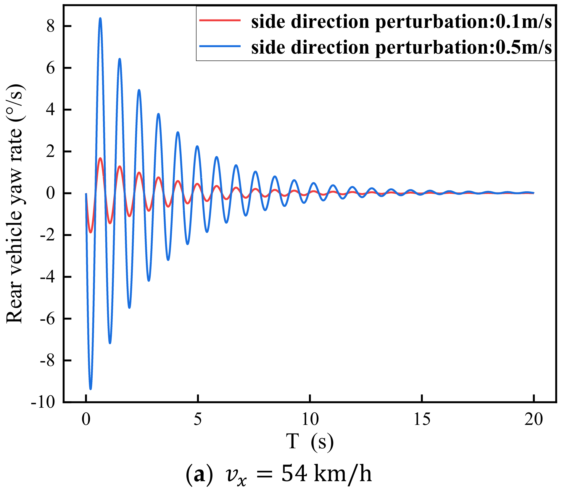
Figure 9 depicts the response curve of the rear vehicle’s initial yaw rate under different driving speeds. The initial states are represented by and . When the system’s driving speed is 54 km/h, the yaw rate of the rear vehicle converges to zero over time, regardless of the lateral velocity disturbance. When is 60.48 km/h, the yaw rate of the rear vehicle continues to oscillate. However, when is 75 km/h, the yaw rate of the rear vehicle oscillates and amplifies continuously, with a significantly greater amplitude than that of the front vehicle’s divergence. At approximately 19 s, the amplitude of the rear vehicle’s yaw rate reaches about 80°/s. At this point, the rear vehicle becomes severely unstable and becomes unable to maintain formation.
From the above analysis, it can be seen that when the driving speed of the system is less than the critical speed, the yaw motion of the system oscillates and converges under different lateral disturbances. When the driving speed of the system is greater than the critical speed, the yaw motion of the system oscillates and diverges under different lateral disturbances. In other words, whether the lateral motion of the system is stable is only related to the driving speed. The magnitude of the lateral disturbance only affects the amplitude of the system motion response oscillation and the speed of convergence or divergence.
6. Conclusions
(1) A virtual articulation-based dynamic model for the high-speed steering system of intelligent vehicle platoons is developed. The study initially focuses on assessing how structural characteristics and system parameters affect the motion stability of the system, culminating in the proposal of a virtual articulated point-based control strategy for high-speed steering.
(2) The system’s damping ratio is defined according to nonlinear dynamics theory, having utilized the characteristics of the damping ratio to determine the dynamic critical speed necessary for the stable operation of the intelligent platoon system. Sensitivity analysis and control variable analysis methods are employed to examine the intelligent platoon’s structural characteristics and the impact of system parameters, having subsequently validated the proposed control strategy’s accuracy. Additionally, this approach offers novel insights into lateral motion stability analysis for vehicle platoons.
(3) The study employs time domain analysis to analyze the lateral angular velocities of both front and rear vehicles within the system when they are subjected to external disturbances. It is found that, away from the critical speed, the system’s stability primarily depends on the current driving speed, while external disturbances impact both the amplitude of system oscillations and the convergence or divergence speed.
Additionally, in developing the system model, this study focuses on the nonlinear steering and tire models. Future work will concentrate on how the suspension system influences the system’s motion stability.
Author Contributions
Study conception and design: G.X. and Z.L.; data collection: N.S.; the analysis and interpretation of results: Z.L. and N.S.; draft manuscript preparation: Z.L. and Y.Z. All authors have read and agreed to the published version of the manuscript.
Funding
This research was funded by the National Natural Science Foundation of China (61803206), the key R-D Program of Jiangsu Province (BE2022053-2), and the Nanjing Forestry University Youth Science and Technology Innovation Fund (CX2018004).
Data Availability Statement
The original contributions presented in the study are included in the article, further inquiries can be directed to the corresponding author.
Conflicts of Interest
The authors declare no conflicts of interest.
Nomenclature
| Symbol | Description | Value |
| The equivalent moment of inertia of the rack to the kingpin | 120 kg·m2/rad | |
| The moment of inertia of the steering column | 120 kg·m2/rad | |
| The moment of inertia of the front wheel around the kingpin | 130 kg·m2/rad | |
| The equivalent stiffness of the gear | 35,000 N/rad | |
| The torsional stiffness of the steering wheel and rack meshing | 35,000 N/rad | |
| The equivalent deformation stiffness of the steering tie rod | 35,200 N/rad | |
| The equivalent damping of the rack and pinion meshing | 250 N·m·s/rad | |
| The torsional damping of the steering wheel | 250 N·m·s/rad | |
| The rotational damping of the front wheel around the kingpin | 250 N·m·s/rad | |
| The equivalent damping of the deformation of the steering tie rod | 250 N·m·s/rad | |
| Front and rear vehicle quality | 1980, 1880 kg | |
| Moment of inertia of front and rear vehicles | 5020, 4150 kg·m2 | |
| The distances from the front axle to the center of mass, from the rear axle to the center of mass, and from the center of mass to the virtual articulated point | m | |
| Steering wheel angle and steering wheel angle | rad | |
| Yaw angle and yaw rate | rad, rad/s | |
| Longitudinal speed and lateral speed | m/s | |
| Front axle sideslip angle and rear axle sideslip angle | rad | |
| the angle between the front and rear axle lines | rad |
References
- Li, S.-E.; Zheng, Y.; Li, K.; Wang, J. An overview of vehicular platoon control under the four-component framework. In Proceedings of the 2015 IEEE Autonomous Vehicles Symposium (IV), IEEE, Seoul, Republic of Korea, 28 June–1 July 2015; pp. 286–291. [Google Scholar]
- Guanetti, J.; Kim, Y.; Borrelli, F. Control of connected and automated vehicles: State of the art and future challenges. Annu. Rev. Control. 2018, 45, 18–40. [Google Scholar] [CrossRef]
- Montanino, M.; Punzo, V. On string stability of a mixed and heterogeneous traffic flow: A unifying modelling framework. Transp. Res. Part B Methodol. 2021, 144, 133–154. [Google Scholar] [CrossRef]
- Solyom, S.; Idelchi, A.; Salamah, B.B. Lateral control of vehicle platoons. In Proceedings of the 2013 IEEE International Conference on Systems, Man, and Cybernetics, IEEE, Manchester, UK, 13–16 October 2013; pp. 4561–4565. [Google Scholar]
- Alleleijn, J.; Nijmeijer, H.; Öncü, S.; Ploeg, J. Lateral String Stability of Vehicle Platoons; Eindhoven University of Technology: Eindhoven, The Netherlands, 2014. [Google Scholar]
- Hu, Z.; Su, R.; Wang, Y.; Wang, B.; Huang, L.; Lu, Y. Security Enhancement for Longitudinal Vehicle Platooning Under Denial-of-Service Attacks: From Resilient Controller Design Perspective. IFAC-PapersOnLine 2023, 56, 1088–1093. [Google Scholar] [CrossRef]
- Hu, Z.; Su, R.; Zhang, K.; Xu, Z.; Ma, R. Resilient Event-Triggered Model Predictive Control for Adaptive Cruise Control under Sensor Attacks. IEEE/CAA J. Autom. Sin. 2023, 10, 807–809. [Google Scholar] [CrossRef]
- Bubnicki, Z. Modern Control Theory; Springer: Berlin, Germany, 2005. [Google Scholar]
- Dorf, R.C.; Bishop, R.H. Modern Control Systems, 12th ed.; Pearson: London, UK, 2011. [Google Scholar]
- Zhang, L.; Orosz, G. Motif-based design for connected vehicle systems in presence of heterogeneous connectivity structures and time delays. IEEE Trans. Auton. Transp. Syst. 2016, 17, 1638–1651. [Google Scholar] [CrossRef]
- Jin, I.G.; Orosz, G. Optimal control of connected vehicle systems with communication delay and driver reaction time. IEEE Trans. Auton. Transp. Syst. 2016, 18, 2056–2070. [Google Scholar]
- Qin, Y.-Y.; Wang, H. Improving Traffic Safety via Traffic Flow Optimization of Connected and Automated Vehicles. China J. Highw. Transp. 2018, 31, 202–210. [Google Scholar]
- Qin, Y.; Wang, H. Analytical framework of string stability of connected and autonomous platoons with electronic throttle angle feedback. Transp. A Transp. Sci. 2021, 17, 59–80. [Google Scholar] [CrossRef]
- Qin, Y.-Y.; Wang, H. Asymptotic stability analysis of traffic flow mixed with connected vehicles. J. Harbin Inst. Technol. 2019, 51, 88. [Google Scholar]
- Feng, S.; Zhang, Y.; Li, S.-E.; Cao, Z.; Liu, H.X.; Li, L. String stability for vehicular platoon control: Definitions and analysis methods. Annu. Rev. Control. 2019, 47, 81–97. [Google Scholar] [CrossRef]
- Yadlapalli, S.K.; Darbha, S.; Rajagopal, K.R. Information flow and its relation to stability of the motion of vehicles in a rigid formation. IEEE Trans. Autom. Control. 2006, 51, 1315–1319. [Google Scholar] [CrossRef]
- Klinge, S.; Middleton, R.H. String stability analysis of homogeneous linear unidirectionally connected systems with nonzero initial conditions. In Proceedings of the IET Irish Signals and Systems Conference (ISSC 2009), Dublin, Ireland, 10–11 June 2009. [Google Scholar]
- Besselink, B.; Johansson, K.H. String stability and a delay-based spacing policy for vehicle platoons subject to disturbances. IEEE Trans. Autom. Control. 2017, 62, 4376–4391. [Google Scholar] [CrossRef]
- Jing, Y.-S.; Gu, Q.-F.; Yao, Z.-H. Review of Stability Analysis Method for Mixed Traffic Flow with Connected Automated Vehicles. J. Southwest Jiaotong Univ. 2022, 57, 927–940. [Google Scholar]
- Zheng, Y.; Li, S.E.; Wang, J.; Cao, D.; Li, K. Stability and scalability of homogeneous vehicular platoon: Study on the influence of information flow topologies. IEEE Trans. Auton. Transp. Syst. 2015, 17, 14–26. [Google Scholar] [CrossRef]
- Zheng, Y.; Li, S.E.; Li, K.; Wang, L.-Y. Stability margin improvement of vehicular platoon considering undirected topology and asymmetric control. IEEE Trans. Control. Syst. Technol. 2015, 24, 1253–1265. [Google Scholar] [CrossRef]
- Liu, Y.; Gao, H.; Zhai, C.; Xie, W. Internal stability and string stability of connected vehicle systems with time delays. IEEE Trans. Auton. Transp. Syst. 2020, 22, 6162–6174. [Google Scholar] [CrossRef]
- Liu, Y.; Gao, H. Stability, scalability, speedability, and string stability of connected vehicle systems. IEEE Trans. Syst. Man Cybern. Syst. 2021, 52, 2819–2832. [Google Scholar] [CrossRef]
- Kang, J.-Y.; Burkett, G., Jr.; Bennett, D.; Velinsky, S.A. Nonlinear vehicle dynamics and trailer steering control of the towplow, a steerable articulated snowplowing vehicle system. J. Dyn. Syst. Meas. Control. 2015, 137, 081005. [Google Scholar] [CrossRef]
- Wei, H.; Xu, Y.; Wang, X.; Li, L. Nonlinear shimmy and dynamic bifurcation in vehicle system with driver steering input. Proc. Inst. Mech. Eng. Part D J. Automob. Eng. 2023. [CrossRef]
Figure 1.
Ten-degrees-of-freedom-virtual articulated intelligent platooning system model diagram.

Figure 2.
Virtual articulated point and its force analysis.

Figure 3.
Stability diagram of system stability at critical steering wheel angles.

Figure 4.
Sensitivity analysis of vehicle stability to its intrinsic characteristics.

Figure 5.
Intelligent vehicle platooning stability control strategy.

Figure 6.
System damping ratio characteristic curve.

Figure 7.
The impact of a single-parameter variation on the dynamic critical speed of the system.

Figure 8.
Response curve of front vehicle’s yaw rate under different driving speeds.


Figure 9.
Response curve of rear vehicle’s yaw rate under different driving speeds.


Table 1.
Tire parameters.
| Parament | Value | Parament | Value |
|---|---|---|---|
| 15,650, 15,120 | 1.29, 9.3, −0.8 | ||
| 0 | 0 |
Disclaimer/Publisher’s Note: The statements, opinions and data contained in all publications are solely those of the individual author(s) and contributor(s) and not of MDPI and/or the editor(s). MDPI and/or the editor(s) disclaim responsibility for any injury to people or property resulting from any ideas, methods, instructions or products referred to in the content. |
© 2024 by the authors. Licensee MDPI, Basel, Switzerland. This article is an open access article distributed under the terms and conditions of the Creative Commons Attribution (CC BY) license (https://creativecommons.org/licenses/by/4.0/).
Share and Cite
MDPI and ACS Style
Xiao, G.; Li, Z.; Sun, N.; Zhang, Y. Research on the Stability Control Strategy of High-Speed Steering Intelligent Vehicle Platooning. World Electr. Veh. J. 2024, 15, 169. https://doi.org/10.3390/wevj15040169
AMA Style
Xiao G, Li Z, Sun N, Zhang Y. Research on the Stability Control Strategy of High-Speed Steering Intelligent Vehicle Platooning. World Electric Vehicle Journal. 2024; 15(4):169. https://doi.org/10.3390/wevj15040169
Chicago/Turabian StyleXiao, Guangbing, Zhicheng Li, Ning Sun, and Yong Zhang. 2024. "Research on the Stability Control Strategy of High-Speed Steering Intelligent Vehicle Platooning" World Electric Vehicle Journal 15, no. 4: 169. https://doi.org/10.3390/wevj15040169