A Sustainable Decision-Making Framework for Transitioning to Robotic Welding for Small and Medium Manufacturers

School of Integrated Sciences, College of Integrated Science and Engineering, James Madison University, Harrisonburg, VA 22801, USA
*
Author to whom correspondence should be addressed.
Sustainability 2018, 10(10), 3651; https://doi.org/10.3390/su10103651
Submission received: 17 September 2018
/
Revised: 8 October 2018
/
Accepted: 10 October 2018
/
Published: 12 October 2018
(This article belongs to the Special Issue Sustainable Intelligent Manufacturing Systems)
Abstract
:Small and medium-sized enterprises (SMEs) face challenges in implementing industrial robotics in their manufacturing due to limited resources and expertise. There is still good economic potential in using industrial robotics, however, due to manufacturers leaning toward newer technology and automated processes. The research on sustainability decision-making for transitioning a traditional process to a robotic process is limited for SMEs. This study presents a systemic framework for assessing the sustainability of implementing robotic techniques in key processes that would benefit SMEs. The framework identifies several key economic, technical, and managerial decision-making factors during the transition phase. Sustainability assessments, including cost, environmental impact, and social impact, are used in the framework for engineers and managers to evaluate the technical and sustainability trade-offs of the transition. A case study was conducted on a typical US metal fabrication SME focusing on transitioning a shielded metal arc welding (SMAW) process to a robotic gas metal arc welding (GMAW) process. A sustainability assessment was conducted following the framework. The results suggest that the transition phase involves numerous factors for engineers and managers to consider and the proposed framework will benefit SMEs by providing an analytical method for industrial robotics implementation decision-making.
1. Introduction and Literature Review
As small and medium-sized enterprises (SMEs) move toward Industry 4.0, their manufacturing environments are changing. These changes include automation realization on the shop floor and increased customer expectations regarding carbon footprint reduction, waste, and unemployment [1]. To address these concerns, SMEs acknowledge the importance of sustainable manufacturing to assist in the transition from traditional to robotic manufacturing processes [2,3]. Statistics show that in 2015, robotics sales increased by 15%, which is the highest percentage increase ever recorded for one year. The two main industries that contributed to the increase in sales of industrial robotics are the automotive and electronic industries [4]. This paints a picture that manufacturing environments are leaning toward robotic processes to meet increased globalization throughout the world. SMEs consist of mostly privately owned businesses that are managed by a single owner [5]. The management structure differs greatly from larger organizations that have more capital for research projects and initiatives. The current economic focus is local; however, as globalization continues to increase, exportation will increase for SMEs in the United States. Therefore, automating processes will be necessary [6]. However, the main concern is the scarcity of resources within SMEs [7].
Research on planning and implementing robotics in manufacturing processes focuses largely on decision support for the transition phase. Deuse et al. [8] proposed a system architecture that includes an internet portal joining customers and robotics manufacturers for data and information communication, a database containing technical robotic solutions, a planning and decision support system for component selection and process planning, and a simulation where proposed processes can be reviewed. The National Institute of Standards and Technology (NIST) identified several challenges associated with robotic transition and indicated that while robotics are becoming increasingly easier to use, they are more difficult to integrate due to the sacrifices required to reduce cost and broaden application scope. The challenges include locating the part, grasping the part, moving the part, placing the part within the assembly, manipulating parts, fastening, and other moves that need to be calibrated [2]. Talalaev et al. [9] developed a methodology that considers product analysis and robot cell configuration, and applied the method in a metal inert gas or metal active gas (MIG/MAG) process. Sarkans and Roosimölder [10] used a modular and systems approach with multiple system layers such as process, system configuration, installation, variables, program, and simulation to assist robotic implementation. Research has also considered other aspects of robotic use in production systems, such as coordination, scheduling, reuse of process knowledge, and monitoring system control [10,11,12,13,14,15,16,17,18]. However, a decision support system that focuses on sustainability is lacking in transitioning traditional processes to robotic manufacturing processes.
Welding is a materials joining process in which two parts are coalesced at their contacting surfaces by a suitable application of heat and/or pressure [19]. Welding is employed in industrial sectors such as automotive, aerospace, shipbuilding, construction, nuclear, energy/power generation, electronics, household appliances, petrochemicals, and machinery fabrication [20,21,22]. Studies on the sustainability of welding processes have been carried out by multiple researchers [23,24,25,26,27]. Chang et al. [28] conducted a study of environmental impact assessment and social life cycle assessment (LCA) of welding technologies, and found that manual welding results in lower productivity and higher health risk than automatic welding processes. Nakhla et al. [29] calculated shield gas production and transportation carbon emissions associated with a welding process and showed that the environmental impact of weld gas utilization expands beyond the release of the weld gas into the atmosphere, and the use of a weld gas regulator can result in significant savings for the production process and reduce the amount of greenhouse gas emission. Sproesser et al. [30] studied the energy efficiency of gas metal arc welding (GMAW) by using a tandem GMAW (TGMAW) and found that electricity consumption for higher-power TGMAW was decreased by 23% and the process time was reduced by 55%. Sangwan et al. [31] conducted an LCA study on a welding training section and used a CML (centrum voor milieuwetenschappen, a Dutch phrase) midpoint assessment method to evaluate environmental impact in 13 categories. The study found that machine and equipment copper and steel production is the major polluter, and copper is the major contributor in the end-of-life phase. Sproesser et al. [32] compared the environmental impact of manual metal arc welding (MMAW), GMAW, laser arc hybrid welding (LAHW), spray, and modified arch welding processes, and found that MMAW had the highest environmental impact for an operation on 20 mm thick structural steel with a weld bead length of 1 m. Vimal et al. [33] studied the shielded metal arc welding (SMAW) process and identified five sustainability strategies: energy modeling and optimization studies, waste minimization and disposal studies, process parametric optimization, process emission studies, and employee skill training and involvement programs. The study found that the waste minimization and disposal strategy resulted in improved environmental performance and conservation of materials. From the economic aspect, several cost-effective approaches have been used in welding parametric optimization, such as the Taguchi method and genetic algorithms [22]. Jármai et al. [34] conducted a cost optimization study on cylindrical orthogonally stiffened shells and revealed that orthogonal stiffening could result in more than 50% savings in material and manufacturing related costs. Patrick et al. [35] showed that material costs represent a small percentage of the total cost (welding consumables, 8% to 15%, and power and equipment, 2% to 5%) of the overall welding cost in a typical US operation, and labor and overhead costs represent around 80–85% of total operating cost. The study suggested that changing SMAW to flux-cored arc welding can reduce labor cost and increase productivity. From the social aspect, health hazards and risks are the main concerns related to welding processes [22]. Welding fumes mainly consist of heavy metals such as chromium (Cr), manganese (Mn), nickel (Ni), and iron (Fe) [36]. Inhalation exposure may lead to acute or chronic respiratory disease. Risks include asphyxiation due to dangerous inhalants, damage to skin and eyes due to ultraviolet light, chemical or electrical fires, and long-term negative effects from fumes [37,38]. Hutchins et al. [39] used a process-based approach to characterize the social impacts of a welding process and emphasized that it is important to clearly identify the scope of activities related to products/processes of interest, life cycle stages, and the source and type of impact/risk in order to assess the social dimension of sustainability. In addition, studies revealed that welders’ salaries are fair and sufficient to sustain a good quality life [28]. The focus of current welding sustainability research efforts, however, has been largely on one pillar of sustainability: economic, environmental, or social. Research on welding process transition and sustainability decision-making is very limited.
To address the knowledge gap of sustainability decision support for robotic welding process implementation in SMEs, the objective of this research is to propose a sustainable decision-making framework for manufacturing engineers and managers to analyze economic, environmental, and social outcomes during the transition phase of robotics for intelligent manufacturing systems. Specifically, within this paper a framework is presented focusing on transitioning a manual welding process to a robotic welding process and evaluating the sustainability performance. The framework will assist SMEs to move toward a robotic manufacturing environment by concurrently considering economic, environmental, and social outcomes.
2. Methodology
The methodology used in this study follows the framework displayed in Figure 1.
The framework identifies sustainability factors that will be involved in the decision-making. For example, material, energy, labor, and equipment and fixtures are input factors that directly affect the economic, environmental, and social impact of the process. During the transition phase, layout, safety, human resources, training, scheduling, and quality are identified as transformative factors because they are related to the changes during the robotic transition and are key factors in effectively implementing the new process. In order to compose a transition plan, economic, environmental, and social impact assessments need to be conducted to evaluate the overall performance of the manual process and the robotic process. The decision-making will be based on the results from the sustainability assessments and the transformative factors, which are further explained in the following sections.
2.1. Inputs and Transformative Factors
Inputs: There are three major inputs: materials, energy, and equipment and fixtures. Materials for welding processes typically include steel, aluminum, zinc, nickel, titanium, and brass. Filler metal and electrodes may also be necessary depending on the welding process. Energy is constantly used in the production process, mostly consisting of electricity usage and heating and cooling for the facility. It is noted that robots do not have to work in bright lighting, therefore energy savings occur compared to manual operations [40]. Equipment and fixtures consist of the machinery and tools that are necessary to produce the product. For example, within welding processes this would consist of the shield gas container, welding gun, product fixtures to properly weld the part, etc. When the transformation to automation occurs, the equipment will consist of the robot and any subassemblies required.
Transformative factors: There are numerous factors involved in the transition phase. However, several key considerations include safety, human resources and training, layout, scheduling, and quality. Safety is always a priority when transforming a process from manual operation to robotic automation. For example, Occupational Safety and Health Administration (OSHA) standard 1910, subpart Q states that there shall be a safety-type disconnecting switch or a circuit breaker near the machine for manual resistance seam welding. This is to prevent electrocution. Similarly, all manual welding processes must have effective guarding devices such as an electronic eye safety circuit or adequate guards [41]. Surveying past accidents, it can be seen that many robot accidents happened during the programming sequences and during maintenance of the robot [41]. Therefore, a hazard analysis of the robotic system is always recommended and the following factors should be considered:
- Startup and command or programming procedures
- Location and installation requirements
- Possible human errors
- Typical robot malfunctions
- Scheduled and unscheduled maintenance
OSHA also recommends implementing safeguarding and awareness devices, and providing adequate training to programmers, operators, and maintenance workers who are going to interact with the robot daily to prevent future accidents from occurring.
Related to human resources, another transformative factor is human-centric effects from technological change. Change is not always well received on shop floors. For example, employee unions could raise concerns about replaced operators. Retraining programs for current and replaced employees are often introduced to keep them up to date. Human error is one key reason companies implement automation [42]. When companies purchase robots, they are buying standard products that can be measured and tested for reliability and performance, unlike human workers [43]. Therefore, the new roles of human workers need to be redefined in automated systems.
To better understand how to implement robotic work cells, this study partitions robotic cells into three types: blocking, no-wait, and interval. In a blocking cell, the part to be processed cannot be loaded unless the part that is completed is moved and the area is unoccupied. With the no-wait pickup criterion, the part must be removed from the machine and moved directly to another machine. In interval robotic cells, each stage has a specific interval of time during which a part can be processed [44]. The following assumptions are made in this study: (1) the robot cannot be instructed to load an occupied machine, and (2) the robot cannot be instructed to unload an unoccupied machine.
As for the layout transition, the following factors need to be evaluated [45]:
- Structural obstructions
- Energy drop in locations (electrical, air)
- Clear height below the structure, piping, fire protections
- Forklift travel aisles
- Raw material delivery locations
- Current machine layouts
Often, simulation is necessary before implementation to make sure the current layout will suffice for production. The geometric simulation uses 3D visualizations, collision detection, and offline programming methods to see the robotic work cell before implementation. The main issue with all simulation software is the overall affordability for SMEs [46]. Therefore, the costs of the associated planning need to be considered.
The International Organization for Standardization (ISO) defines quality as “the totality of features and characteristics of a product or service that bear on its ability to satisfy stated and implied needs” [47]. A high-quality weld must adhere to the following characteristics:
- It must be functional for its required lifespan.
- It must be manufactured with specified materials along with design specifications for the process.
- It must be maintained properly throughout its required lifespan.
A good way to test welds is with a destructive examination. If it does not meet the standard, the weld can be repaired so that it is brought up to acceptable standard. With manual SMAW, the key quality consideration is the correct implementation of the welding procedure and the skillful manipulation of the welding arc by the operator. In robotic GMAW, the key quality considerations include proper design of the product, optimizing the welding process, feedback control of the process, and diagnosis of the cause of quality disturbances.
2.2. Economic Assessment
To assess the implementation of industrial robotics, the implementation team should select a series of alternative choices based on monetary investment. This can be done through life cycle costing (LCC), which considers the sum of all recurring and one-time costs over the full lifespan of the robot. They include the purchase price, installation costs, operating costs, and maintenance and upgrade costs [48]. Through this methodology, the team can determine the least costly design alternatives for implementation to be effective. The cost calculations for a typical welding process are shown below [49].
Total cost per unit (C) of the process includes labor cost (LC), electrode cost (EC), shield gas cost (SGC), electrical power cost (EPC), robotic cost (RC), safety system cost (SSC), transition cost (TC), and equipment cost (EC). The cost per unit equation is displayed with the costs that are associated with each functional unit:
Cost per unit = LC + EC + SGC + EPC + RC + SSC + TC + EC
To calculate the labor cost associated with manual and robotic GMAW, the following equation is used:
where weld deposit is the portion of a fusion weld that has been completely melted during welding; deposition rate is the rate that weld metal can be deposited by a given electrode or welding wire, expressed in kg per hour; and operating factor is the time that the welder is actually welding, which is the arc time divided by the total hours worked multiplied by 100 and expressed as a percentage.
The cost of the shield gases can be calculated with the following equation:
SGC = Arc time × Gas flow rate × Cost of gas per cubic foot
Once shielding gas cost is considered, electrical power can be calculated with:
Electrode cost can be calculated with the following equation:
where wire rate per unit length is the amount of welding material in unit length (e.g., g/cm).
EC = Arc time × Wire feed rate × Wire rate per unit length × Wire cost
Transition cost includes costs associated with the labor time for installation and coordination of production (information flow). This is because a new system takes time to adapt to a production environment and become stable. The equipment cost accounts for initial cost, annual maintenance, and end-of-life depreciation value. Interest rate will be accounted for to consider the time value of money. The overall end-of-life value is based on the scrap amount of the valuable materials, complexity of the disassembly, number of devices ending their lives, and pureness of the disassembling components. By evaluating the end-of-life strategy, the overall cost over the robot’s life cycle can be determined [50].
2.3. Environmental Impact Assessment
Life cycle assessment (LCA) can be used to determine the potential environmental impacts of a process. LCA contains four main phases: goal and scope definition, life cycle inventory, impact assessment, and interpretation [51]. Goal and scope definition identifies the objective, system boundary, and functional unit of the product or system to be analyzed. A functional unit can be a unit length of welding for a particular part or a complete operation to finish a welding part. A cradle-to-gate analysis accounts for material production, equipment manufacturing, and energy and material consumption during the welding process, while a gate-to-gate analysis focuses on the welding process itself, not counting stages before manufacturing. The life cycle inventory compiles energy and material flows involved in the system boundary. Typical information in the welding life cycle assessment includes amount of material (e.g., feedstock, ancillary materials), energy required by the process (e.g., electricity), equipment usage, and hazardous materials. Once the inventory of different ideas of possible impact is collected, inventory indicators are converted into a series of impact categories through environmental impact assessment methods such as ReCiPe, CML, and Tool for Reduction and Assessment of Chemicals and Other Environmental Impacts (TRACI) [52,53,54]. A typical list of impact categories includes acidification potential, climate change, eutrophication potential, freshwater aquatic ecotoxicity potential, freshwater sediment ecotoxicity potential, human toxicity potential, ionizing radiation, marine aquatic ecotoxicity potential, marine sediment ecotoxicity potential, photochemical oxidants, abiotic depletion potential, ozone depletion potential, and terrestrial ecotoxicity potential [31]. Once the impacts are completed, the last step of analyzing the LCA is to interpret the results, which leads to the conclusion and interpretation [55].
2.4. Social Impact Assessment
Social life cycle assessment (SLCA) assesses the social and socioeconomic aspects of producing products and their potential positive and negative impacts along the robot’s life cycle [56]. The framework is the same as the LCA, beginning with an objective, scope, and functional unit. In goal and scope definition, stakeholders involved in this technology transition shall be included. These stakeholders can provide input on impacts and within the assessment itself. Location is another factor that affects social impact assessment. In some locations, assessment may also need to include political attributes such as laws and policies. Therefore, in defining a goal and scope, practitioners need to consider various factors to identify stakeholders and potential impacts to analyze. Social life cycle inventory collects both quantitative and qualitative data from processes to be analyzed. Quantitative data might include number of working hours, injury rate, and number of local employees hired. Qualitative data can be collected when the metrics are difficult to quantify, such as public opinion and social relationships. In the impact assessment stage, some common social aspects around manufacturing processes are related to wages and compensation, safety, personal and technical growth, and social interaction [57]. For the robotic welding process transition in this study, social impact assessment primarily focuses on fair salaries and health and safety [58]. Fair salaries can be assessed by evaluating the difference between the local performance standard (Plocal), e.g., average operator wage, and the work cell performance (Pj), e.g., wage for the operator position under study [3].
Pdifference = Pj − Plocal
In addition, wages can be compared with the national poverty threshold in order to identify the operator’s quality of life. However, national poverty thresholds vary considerably among countries, and poverty here is relative poverty such that the standard of living with a certain income is high enough to satisfy basic needs (e.g., water, food, clothing, housing, and basic healthcare), but still significantly lower than that of the majority of the population under consideration [59].
In order to quantitatively estimate health and safety impact, a model is used to calculate the hazard figure (Gehfahrdungszahl, GZ) of the welding process [60]. It can be calculated with the following equation:
GZs = (Ep × Wp) × L × R × Kb
where Ep is the emission factor of the specific substance per functional unit; Wp is the potential effect of the specific substances in the fume (by comparison, it can be assumed as 1 if the deposition material is the same); L is the ventilation factor; R is the spatial factor (by comparison, it can be assumed as 1 if the location condition is the same); and Kb is the factor of relative distance of head/body and fume source from 1 to 4, with 1 indicating far distance and 4 close distance [58,60].
2.5. Application and Decision-Making of the Framework
After all assessments, a transition plan will be formulated at the end of the systematic methodology. For SMEs, due to capability limitations, some of the above methods might not be conducted professionally. However, the proposed framework provides a guideline for economic, environmental, and social assessments. The practice can be flexible in the condition that the three pillars of sustainability are fully considered. A decision guideline/algorithm is presented for SMEs to follow.
The transition plan should be completed by a team of stakeholders during the transition. For example, technical personnel such as engineers and technicians need to come up with an initial plan for implementation. Then personnel who are in charge of cost, environmental regulation compliance, and safety assurance conduct independent assessments (LCC, LCA, and SLCA). The assessment results should reflect both satisfaction and dissatisfaction with the initial plan. The dissatisfaction will be revisited by the technical team and the corresponding team (e.g., safety) until a solution is found and the requirements are met (Figure 2).
3. Case Study
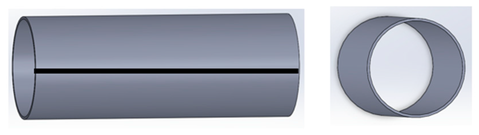
To demonstrate the application of the proposed framework, presented is a case study to convert a manual shielded metal arc welding process to a robotic gas metal arc welding process [49] for welding an aluminum cylinder (Figure 3).
3.1. Case Background
The function unit is a 300 mm welding part, which is an aluminum cylinder with the dimensions displayed in Table 1 below.
Shielded metal arc welding is a process that uses a consumable electrode consisting of a filler metal rod coated with chemicals that provide flux and shielding. Coating materials include powdered cellulose mixed with oxides, carbonates, and other ingredients held together by a silicate binder. This process is usually performed manually [19]. GMAW is an arc welding process in which there is a consumable bare metal wire that is continuously fed through a welding gun. Wire diameters range from 0.8 to 6.5 mm. With GMAW, shielding the weld is necessary when using gases such as argon, helium, and carbon dioxide. The continuously fed welding gun and shielding gas remove the possibility of slag forming from the weld bead and ensures a high-quality weld.
Figure 4 describes the manual process work cell layout that is to be changed.
3.2. Inputs
Due to the complex mechanism of robotics, it uses more energy to operate the machine than a manual device does during the same time period. However, when processing a part, in this case 300 mm welding line, a robotic welder takes less time (28.35 s) than a manual welder (78.74 s). Nevertheless, the robotic welder has higher power efficiency (80%) than the manual device (50%). When not working, the idle power for the robotic welder is 60 w. The electric power specifications are shown in Section 3.4. For the equipment setup, within a manual welding process, typical components of each work cell consist of the following: wire feed unit, power source, fixture, part or component being welded, and welding gun. Within a robotic work cell, most of these components are combined into a single machine. The material used in this case study is aluminum. Shield gas is contained in the manual welding electrode. The rod’s material consists of mostly aluminum for both manual and robotic processes [61]. This is displayed in Table 2.
3.3. Transformative Factors
Quality: A major factor that should be considered is the overall quality of the product that the customer will receive. One of the positives about implementing robotics is that the room for error is minimal compared to human operators. The quality management, however, involves several aspects, such as welding parameters and geometric variables of the torch and the workpiece (e.g., torch angle and cord length). Often, an experienced welding operator generates better-quality welding joints compared to beginners with less experience.
Safety: Within manual arc welding, a key safety issue is the arc rays generated by the welding equipment. Therefore, it is essential that eyes and skin are protected from radiation exposure. If a helmet is not worn, the UV radiation can cause an eye burn known as “welder’s flash”. Another critical factor is ventilation. Spaces that do not meet the standards should be equipped with mechanical ventilating equipment that exhausts at least 2000 cfm of air for each welder [41]. Another factor to consider when operating the equipment is not entering the robotic cell while it is in automatic operation. Mechanical safety devices should be in place, such as fences and barriers, light curtains, door interlocks, warning lights, and floor markings. These need to be checked regularly [41].
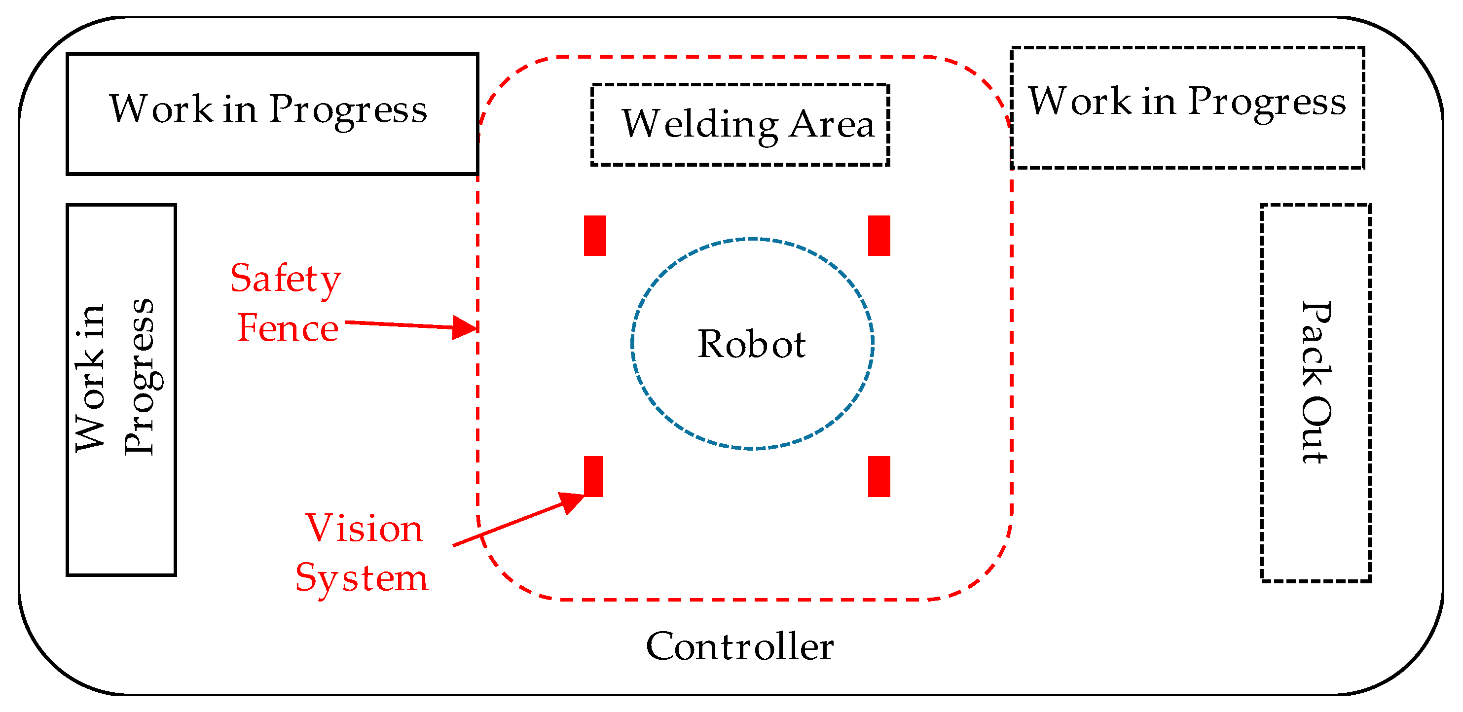
Layout: Determining the factors and costs associated with layout planning is complex [45]. In this study, a fully automated system is implemented. Therefore, some of the major physical factors that we need to consider are the current characteristics of the work area such as electrical lines, water lines, current assembly areas, Heating, Ventilation, and air conditioning (HVAC) systems, and safety systems.
Changes to the work layout (Figure 5) based on the factors explained above are as follows:
Scheduling: When automation takes place, the capability of processes will also increase. Due to the process cycle time change, the production line will be rebalanced to accommodate the change. In manual welding processes, the process time varies from part to part depending on the operator’s fatigue and experience. In robotic welding, a new schedule with fixed and predictable process times should be generated to reflect this change.
Human Resources: When automation and implementation occur, the company has a few different options for manual welders. They can:
- Be retrained to operate and maintain the robot;
- Be retrained to work in a different area of the factory; or
- Leave the company.
Negative and positive effects of moving a worker or letting a worker go need to be evaluated based on the company situation. Potential positive effects include less liability and lower labor costs. Negative effects could include union issues (if the company is unionized), human worker integrity, and bad publicity. Therefore, the socioeconomic implications are yet to be known [62].
3.4. Economic Assessment
The cost assessment for implementing a robotic welder considers shield gas cost, electric power cost, electrode cost, equipment cost, and labor and overhead cost. All costs are based on the functional unit of one part. The process operates 4000 h per year with two shifts per day.
Shielding gases are used mostly to protect the welding area from oxygen and water vapor. This prevents defects from occurring. Table 3 shows the shield gas and electrode costs.
Electrical power cost is shown in Table 4. The total time that it takes to process one part is shorter for robotic than manual operation. Therefore, the cost per part is lower for robotic than manual. This is calculated using Equation (4).
Arc time is the time it takes for the machine or operator to complete the part. Labor cost is considered in Table 5. The manual welding operator is paid $18/h. No operator is present at the workstation for robotic GMAW. However, the robot requires $500 in maintenance cost each year.
A major difference between manual and robotic welding is the overall amount of parts that can be produced annually. Life cycle costing is conducted to calculate the annual equipment cost (robot and safety systems) based on its lifespan of 10 years (Table 6). Table 7 shows the overall cost comparison considering shielding gas, electrical power, labor, electrode, and equipment costs.
Based on this analysis and the factors considered, the robotic process costs less than the manual process. The additional infrastructure cost associated with the safety systems and automation should be considered once the transformation is made.
3.5. Environmental Impact Assessment
The environmental impact assessment of the transition is a cradle-to-gate analysis focusing on the welding process with the functional unit of one part (300 mm length seam welding). The functional unit is defined consistent with cost assessment, which is one part. The boundary of the analysis includes part material (aluminum in Table 1), welding process ancillary materials (shield gas in Table 3), tools (electrode materials in Table 2), and energy (electricity in Table 4). However, the production of the welding robot and the manual welding device are not included in the boundary due to data availability. Environmental impact results (Table 8) were generated with GaBi software using the ReCiPe method with the Hierarchist perspective [54]. The Ecoinvent database was used to get the environmental impact results [63].
Contribution analysis: When comparing manual versus robotic, the biggest impact category is water depletion. This is due to the processes to create the inputs and materials to weld the components. Climate change is another significant impact in the change from manual to robotic. This is due to the shield gases required for robotic compared with manual welding on the basis that shield gas is contained within the electrode. The shield gases chosen were argon and carbon dioxide. Therefore, these gases contribute to increased climate change when implementation occurs. Fossil fuel depletion results in a greater environmental impact for manual than robotic. This is due to the overall amount of processing and arc time associated with manual SMAW. Because the manual process takes longer, its electricity consumption is higher than the robotic process.
3.6. Social Impact Assessment
The social impact assessment focuses on two aspects, fair salaries and health and safety.
The company in this case study is located in Virginia, United States. Therefore, in the fair salary assessment, the salary rate for the work cell welder ($18/h, $37,440/year) is compared with the average rate in Virginia, the location-specific rate, and the national poverty level.
The statistics shown in Table 9 are from US Occupational Employment Statistics and the data were collected from national, state, and local industries and all occupations [64]. The comparison results show that the local welder wage, $18/h, is $0.69 lower than the national welder mean wage and $3.58 lower than the state (Virginia) welder mean wage, but $0.03 higher than the local welder mean wage. This is because manufacturing companies are mostly located in the northern and eastern part of the state and the living expenses are higher there than in the company’s location (midwestern part of the state). In terms of quality of life, the company welder annual income is $12,840 above the national poverty level, which is defined as a specific dollar amount considered to be the minimum level of resources necessary to meet the basic needs of a family unit (in this case a four-person family) [59]. However, the welder’s annual income is $16,540 less than the Virginia mean income and $3640 less than the local annual income for all occupations. By replacing the manual welding process, the welder has several alternatives, such as getting retrained and relocated to another process, getting retrained to program and operate the automation of the shop floor (a career advancement), or leaving the company. In this study, the robotic welding process is maintained and programed by the engineer. Therefore, a comparison is made based on the case that the welder is retrained to operate other processes on the shop floor (Table 10) [64].
For most of the positions in the same geographic location, the mean wage rates are slightly above or below the welder’s wage ($18/h). If the welder is relocated to metal fabrication, machining, or painting, the salary will increase by $0.49/h, $2.96/h, or $0.75/h, respectively. If the welder is relocated to an assembling or inspection position, the salary will decrease by $1.88/h or $0.18/h, respectively. If the welder is retrained and promoted to a supervisor position, the salary will increase by $8.65/h.
In order to assess the health and safety impact of the process transition, the risk equation (Equation (7)) is used. The welding fume amount is 3.48 g in the manual welding process and 1.08 g in the standard gas metal arc welding process [58]. Therefore, here Ep_manual is set as 3.48 and Ep_robotic is set as 1.08. Since the location conditions and the deposition material are the same for the process transition, Wp, L, and R are set as 1 for comparison. For the manual welding process, the distance between the welder’s body and the hazardous materials is very small, while in the robotic process, the distance between the operator/engineer and the hazardous materials is large. Therefore, the relative distance factor (Kb) for the manual process is set as 4 and for the robotic process is set as 1. The hazard risk is calculated in Table 11.
The final GZ result means that the safety and health risk for the manual welding process is 12.89 times higher than that of the robotic welding process.
In summary, the social impact assessment reveals that unless the welder is promoted to a supervisor position, implementing a robotic process does not significantly affect the welder’s salary if he is relocated to a similar manufacturing process. However, there will be a significant impact on quality of life if the welder has to leave the company and is unable to find a job for a certain length of time. By implementing a robotic process, the company could significantly reduce health and safety risk due to improvements in process setup and reduction of the human–machine distance.
3.7. Decision-Making
With all the results from the above assessments, the decision-making should focus on the environmental impact of the transition, because both production cost per unit and the safety and health impact of robotics perform better than the manual process. The decision will depend on the cost of environmental violations. So two alternative situations are presented:
- The environmental impact of the robotic process does not violate regulations.In this case, the implementation plan can be carried out and use the new robotic process.
- The environmental impact violates regulations.
(1) A solution can be found to mitigate the environmental impact and meet the requirements.
In this case, a team consisting of environmental and technical personnel can seek alternative materials and equipment and conduct assessments to ensure compliance with regulations.
(2) A solution cannot be found to mitigate the environmental impact.
The violation cost (Cv) should be assessed and the overall profit of the robotic process (Pr = Cr − Cv) should be compared with the overall profit of the manual process (Pm). If Pr < Pm, from the economic perspective, the new process should not be implemented due to high violation fees. If Pr < Pm, the new process can be implemented, as the overall benefits exceed the manual process benefit.
4. Discussion and Conclusions
To develop a sustainable approach to transform manual SMAW to robotic GMAW, vital characteristics and factors must be considered. The implementation of the robotic work cell will have social, environmental, and economical effects. Advance planning is the most vital element of sustainable implementation. The proposed methodology provides SMEs with a framework for this transition phase. By mapping out the current state of the process and the overall tangible inputs, the decision-making team can identify problem areas that could limit implementation.
The case study shows that the associated economic costs would benefit from robotic implementation. The cost of manual GMAW was $2.47 per part, while robotic GMAW was $1.42. The production rate would increase with robotic welding. However, supply chain factors should be considered concurrently, especially when it comes to the scheduling of workers, materials, and machines. Therefore, integrating suppliers and customers in preplanning is critical for sustainable implementation. Within environmental life cycle assessment, it was found that the associated environmental impacts would not benefit from robotic implementation. Water depletion and climate change impacts would increase dramatically. It is noted that fossil fuel usage would be less for robotics due to reduced processing time for parts. Socially, training workers to operate and program the robots is vital to counteract the effects of displacing workers. Using a robotic process will decrease safety and health risks for workers. This paper also proposes a decision-making process for SME manufacturing practitioners. The process involves evaluating the outputs from economic, environmental, and social impact assessments and creating a revision plan when certain requirements are not met. However, sustainability decision-making in manufacturing systems is a complex process, because economic, environmental, and social pillars are linked and their relationships need to be explored in order to make a holistic decision. Nevertheless, in the robotic transition, other factors need to be considered. For example, information handling and cybersecurity issues could possibly affect the quality of production. In addition, implementing a new process or technology requires an adaptation period during which process failures and modifications could affect economic, environmental, and social performance of the new process. These factors need to be addressed in further studies.
The framework presented in this study could assist manufacturing engineers and managers in small and medium manufacturing companies with conducting assessments and composing a transition plan to systemically implement robotic technologies on the shop floor.
Author Contributions
Conceptualization, methodology, case study, formal analysis, K.E. and H.Z.; writing-original draft preparation, K.E.; writing–review and editing, H.Z.; Supervision, H.Z.; project administration, H.Z.; Funding acquisition, H.Z.
Funding
The APC was funded by James Madison University School of Integrated Sciences.
Conflicts of Interest
The authors declare no conflicts of interest.
References
- Schröder, C. The Challenges of Industry 4.0 for Small and Medium-sized Enterprises; Friedrich Ebert Foundation: Bonn, Germany, 2015; pp. 1–28. [Google Scholar]
- Marvel, J.A.; Messina, E.R.; Antonishek, B.; Wyk, K.V.; Fronczek, L.J. Tools for Robotics in SME Workcells: Challenges and Approaches for Calibration and Registration; NIST Interagency Internal Report NISTIR-8093; National Institute of Standards and Technology: Gaithersburg, MD, USA, 2015. [Google Scholar]
- Zhang, H.; Haapala, K.R. Integrating sustainable manufacturing assessment into decision making for a production work cell. J. Clean. Prod. 2015, 105, 52–63. [Google Scholar] [CrossRef]
- IFR (International Federation of Robotics). Executive Summary World Robotics 2017 Industrial Robots; International Federation of Robotics: Frankfurt, Germany, 2017; pp. 1–10. [Google Scholar]
- OECD. OECD Glossary of Statistical Terms—Small and Medium-Sized Enterprises (SMEs) Definition. Available online: https://stats.oecd.org/glossary/detail.asp?ID=3123 (accessed on 9 May 2018).
- Seidel, M.; Seidel, R.; Tedford, D.; Cross, R.; Wait, L. A Systems Modeling Approach to Support Environmentally Sustainable Business Development in Manufacturing SMEs. Int. J. Ind. Syst. Eng. 2008, 2, 1305–1313. [Google Scholar]
- McKeiver, C.; Gadenne, D. Environmental Management Systems in Small and Medium Businesses. Int. Small Bus. J. 2005, 23, 513–537. [Google Scholar] [CrossRef]
- Deuse, J.; Roßmann, J.; Kuhlenkötter, B.; Hengstebeck, A.; Stern, O.; Klöckner, M. A Methodology for the Planning and Implementation of Service Robotics in Industrial Work Processes. Procedia CIRP 2014, 23, 41–46. [Google Scholar] [CrossRef]
- Talalaev, R.; Sarkans, M.; Laansoo, A.; Veinthal, R. Methodology for Configuration of Robot Welding Cell for SMEs under Conditions of Small and Medium Sized Production Using MIG/MAG Process. In Proceedings of the 8th International DAAAM Baltic Conference, Tallinn, Estonia, 19–21 April 2012. [Google Scholar]
- Sarkans, M.; Roosimölder, L. Implementation of robot welding cells using modular approach. Est. J. Eng. 2010, 16, 317. [Google Scholar] [CrossRef]
- Ben-Horin, P.; Shoham, M. Singularity analysis of a class of parallel robots based on Grassmann–Cayley algebra. Mech. Mach. Theory 2006, 41, 958–970. [Google Scholar] [CrossRef]
- Bhangale, P.P.; Agrawal, V.P.; Saha, S.K. Attribute based specification, comparison and selection of a robot. Mech. Mach. Theory 2004, 39, 1345–1366. [Google Scholar] [CrossRef] [Green Version]
- Bruccoleri, M. Reconfigurable control of robotized manufacturing cells. Robot. Comput.-Integr. Manuf. 2007, 23, 94–106. [Google Scholar] [CrossRef]
- Dolinsky, J.U.; Jenkinson, I.D.; Colquhoun, G.J. Application of genetic programming to the calibration of industrial robots. Comput. Ind. 2007, 58, 255–264. [Google Scholar] [CrossRef]
- González-Galván, E.J.; Loredo-Flores, A.; Jesús Cervantes-Sánchez, J.; Antonio Aguilera-Cortés, L.; Skaar, S.B. An optimal path-generation algorithm for manufacturing of arbitrarily curved surfaces using uncalibrated vision. Robot. Comput.-Integr. Manuf. 2008, 24, 77–91. [Google Scholar] [CrossRef]
- Gultekin, H.; Ekin Karasan, O.; Akturk, M.S. Pure cycles in flexible robotic cells. Comput. Oper. Res. 2009, 36, 329–343. [Google Scholar] [CrossRef] [Green Version]
- Kim, I.-S.; Son, J.-S.; Yarlagadda, P.K.D.V. A study on the quality improvement of robotic GMA welding process. Robot. Comput.-Integr. Manuf. 2003, 19, 567–572. [Google Scholar] [CrossRef]
- Zacharia, P.T.; Aspragathos, N.A. Optimal robot task scheduling based on genetic algorithms. Robot. Comput.-Integr. Manuf. 2005, 21, 67–79. [Google Scholar] [CrossRef]
- Groover, M.P. Fundamentals of Modern Manufacturing, Binder Ready Version: Materials, Processes, and Systems, 6th ed.; Wiley: Hoboken, NJ, USA, 2015; ISBN 978-1-119-12869-4. [Google Scholar]
- Khan, I. Welding Science and Technology; New Age International Pvt Ltd. Publishers: New Delhi, India, 2009; ISBN 978-81-224-2073-9. [Google Scholar]
- DuPont, J.N.; Babu, S.; Liu, S. Welding of Materials for Energy Applications. Metall. Mater. Trans. A 2013, 44, 3385–3410. [Google Scholar] [CrossRef]
- Alkahla, I.; Pervaiz, S. Sustainability assessment of shielded metal arc welding (SMAW) process. IOP Conf. Ser. Mater. Sci. Eng. 2017, 244, 12001. [Google Scholar] [CrossRef] [Green Version]
- Moon, H.-S.; Na, S.-J. A neuro-fuzzy approach to select welding conditions for welding quality improvement in horizontal fillet welding. J. Manuf. Syst. 1996, 15, 392–403. [Google Scholar] [CrossRef]
- Lim, D.-C.; Gweon, D.-G. In-Process joint strength estimation in pulsed laser spot welding using artificial neural networks. J. Manuf. Syst. 1999, 18, 31–42. [Google Scholar] [CrossRef]
- Datta, S.; Nandi, G.; Bandyopadhyay, A. Application of entropy measurement technique in grey based Taguchi method for solution of correlated multiple response optimization problems: A case study in welding. J. Manuf. Syst. 2009, 28, 55–63. [Google Scholar] [CrossRef]
- Zhang, Y.; Gao, X.; Katayama, S. Weld appearance prediction with BP neural network improved by genetic algorithm during disk laser welding. J. Manuf. Syst. 2015, 34, 53–59. [Google Scholar] [CrossRef]
- Sharma, A. A fundamental study on qualitatively viable sustainable welding process maps. J. Manuf. Syst. 2018, 46, 221–230. [Google Scholar] [CrossRef]
- Chang, Y.-J.; Sproesser, G.; Neugebauer, S.; Wolf, K.; Scheumann, R.; Pittner, A.; Rethmeier, M.; Finkbeiner, M. Environmental and Social Life Cycle Assessment of Welding Technologies. Procedia CIRP 2015, 26, 293–298. [Google Scholar] [CrossRef]
- Nakhla, H.; Shen, J.Y.; Bethea, M. Environmental impacts of using welding gas. J. Technol. Manag. Appl. Eng. 2012, 28, 1–11. [Google Scholar]
- Sproesser, G.; Pittner, A.; Rethmeier, M. Increasing Performance and Energy Efficiency of Gas Metal Arc Welding by a High Power Tandem Process. Procedia CIRP 2016, 40, 642–647. [Google Scholar] [CrossRef]
- Sangwan, K.S.; Herrmann, C.; Egede, P.; Bhakar, V.; Singer, J. Life Cycle Assessment of Arc Welding and Gas Welding Processes. Procedia CIRP 2016, 48, 62–67. [Google Scholar] [CrossRef]
- Sproesser, G.; Chang, Y.-J.; Pittner, A.; Finkbeiner, M.; Rethmeier, M. Life Cycle Assessment of welding technologies for thick metal plate welds. J. Clean. Prod. 2015, 108, 46–53. [Google Scholar] [CrossRef]
- Vimal, K.E.K.; Vinodh, S.; Raja, A. Modelling, assessment and deployment of strategies for ensuring sustainable shielded metal arc welding process—A case study. J. Clean. Prod. 2015, 93, 364–377. [Google Scholar] [CrossRef]
- Jármai, K.; Snyman, J.A.; Farkas, J. Minimum cost design of a welded orthogonally stiffened cylindrical shell. Comput. Struct. 2006, 84, 787–797. [Google Scholar] [CrossRef]
- Patrick, C.W.; Newell, J.; William, F. Understanding Welding Cost: Using Flux-Cored Arc Welding (FCAW) for Cost Reduction and Productivity Improvement. ASME Proc. 2014. [Google Scholar] [CrossRef]
- Antonini, J.M.; Stone, S.; Roberts, J.R.; Chen, B.; Schwegler-Berry, D.; Afshari, A.A.; Frazer, D.G. Effect of short-term stainless steel welding fume inhalation exposure on lung inflammation, injury, and defense responses in rats. Toxicol. Appl. Pharmacol. 2007, 223, 234–245. [Google Scholar] [CrossRef] [PubMed]
- Mistry, P.K.J. Impact of Welding Processes on Environment and Health. Int. J. Adv. Res. Mech. Eng. Technol. 2015, 1, 17–20. [Google Scholar]
- Fard, M.H.; Fard, M.H. Impacts of weldiing on environmental problems and health and solutions to overcome these problems. In Proceedings of the 41st IASTEM International Conference, Paris, France, 15–16 December 2016. [Google Scholar]
- Hutchins, M.J.; Robinson, S.L.; Dornfeld, D. Understanding life cycle social impacts in manufacturing: A processed-based approach. J. Manuf. Syst. 2013, 32, 536–542. [Google Scholar] [CrossRef]
- Robotics Industries Association Robotics and Energy Cost Reduction. Available online: https://www.robotics.org/content-detail.cfm/Industrial-Robotics-Industry-Insights/Robotics-and-Energy-Cost-Reduction/content_id/1047 (accessed on 15 May 2018).
- OSHA Authority for 1910 Subpart Q—1910 Subpart Q|Occupational Safety and Health Administration. Available online: https://www.osha.gov/pls/oshaweb/owadisp.show_document?p_table=STANDARDS&p_id=10133 (accessed on 15 May 2018).
- Myhre, B.A.; McRuer, D. Human error—A significant cause of transfusion mortality. Transfusion 2000, 40, 879–885. [Google Scholar] [CrossRef] [PubMed]
- Wilson, M. Implementation of Robot Systems: An Introduction to Robotics, Automation, and Successful Systems Integration in Manufacturing; Butterworth-Heinemann: Oxford, UK, 2014; ISBN 978-0-12-404749-5. [Google Scholar]
- Dawande, M.; Geismar, H.N.; Pinedo, M.; Sriskandarajah, C. Throughput optimization in dual-gripper interval robotic cells. IIE Trans. 2009, 42, 1–15. [Google Scholar] [CrossRef]
- Rajapakshe, T.; Dawande, M.; Sriskandarajah, C. Quantifying the Impact of Layout on Productivity: An Analysis from Robotic-Cell Manufacturing. Oper. Res. 2011, 59, 440–454. [Google Scholar] [CrossRef]
- Yap, H.J.; Taha, Z.; Md Dawal, S.Z.; Chang, S.-W. Virtual Reality Based Support System for Layout Planning and Programming of an Industrial Robotic Work Cell. PLoS ONE 2014, 9. [Google Scholar] [CrossRef] [PubMed]
- ISO. ISO 9000:2015(EN), Quality Management Systems—Fundamentals and Vocabulary. Available online: https://www.iso.org/obp/ui/#iso:std:45481:en (accessed on 15 May 2018).
- Cole, R.J.; Sterner, E. Reconciling theory and practice of life-cycle costing. Build. Res. Inf. 2000, 28, 368–375. [Google Scholar] [CrossRef]
- Naval Education & Training Center. Navy Steelworker: Volume 1—Navedtra 14250—(Nonresident Training Course); Lulu.com: Morrisville, NC, USA, 2013; ISBN 978-1-304-27337-6. [Google Scholar]
- Kopacek, P.; Kopacek, B. End of Life Management of Automation and IT Devices. IFAC Proc. Vol. 2014, 47, 3503–3508. [Google Scholar] [CrossRef]
- ISO (International Organization for Standardization). ISO 14040:2006 Environmental Management—Life Cycle Assessment—Principles and Framwork; International Organization for Standardization: Geneva, Switzerland, 2006. [Google Scholar]
- Heijungs, R.; Guinée, J.B.; Huppes, G.; Lankreijer, R.M.; Udo de Haes, H.A.; Wegener Sleeswijk, A.; Ansems, A.M.M.; Eggels, P.G.; van Duin, R.; de Goede, H.P. Environmental Life Cycle Assessment of Products: Guide and Backgrounds (Part 1). Available online: https://openaccess.leidenuniv.nl/handle/1887/8061 (accessed on 7 August 2018).
- Guinée, J. (Ed.) Handbook on Life Cycle Assessment: Operational Guide to the ISO Standards; Eco-Efficiency in Industry and Science; Springer: Dordrecht, The Netherlands, 2002; ISBN 978-1-4020-0228-1. [Google Scholar]
- Goedkoop, M.; Heijungs, R.; Huijbregts, M.; Schryver, A.D.; Struijs, J.; van Zelm, R. ReCiPe 2008 A Life Cycle Assessment Method Which Comprises Harmonised Category Indicators at the Midpoint and the Endpoint Level; PRé Consultants: Amersfoort, The Netherlands, 2009. [Google Scholar]
- Keoleian, G.A. The application of life cycle assessment to design. J. Clean. Prod. 1993, 1, 143–149. [Google Scholar] [CrossRef]
- Benoît, C.; Norris, G.A.; Valdivia, S.; Ciroth, A.; Moberg, A.; Bos, U.; Prakash, S.; Ugaya, C.; Beck, T. The guidelines for social life cycle assessment of products: Just in time! Int. J. Life Cycle Assess. 2010, 15, 156–163. [Google Scholar] [CrossRef]
- Lee, W.-T.; Haapala, K.R.; Edwards, M.E.; Funk, K.H. A Framework for the Evaluation and Redesign of Human Work Based on Societal Factors. In Leveraging Technology for a Sustainable World; Springer: Berlin/Heidelberg, Germany, 2012; pp. 575–580. ISBN 978-3-642-29068-8. [Google Scholar]
- Sproesser, G.; Chang, Y.-J.; Pittner, A.; Finkbeiner, M.; Rethmeier, M. Sustainable Technologies for Thick Metal Plate Welding. In Sustainable Manufacturing; Sustainable Production, Life Cycle Engineering and Management; Springer: Cham, Switzerland, 2017; pp. 71–84. ISBN 978-3-319-48513-3. [Google Scholar] [Green Version]
- ASPE Poverty Guidelines. Available online: https://aspe.hhs.gov/poverty-guidelines (accessed on 6 August 2018).
- Spiegel-Ciobanu, V.E. Occupational health and safety regulations with regard to welding and assessment of the exposure to welding fumes and of their effect. Weld. Cut. 2012, 11, 61. [Google Scholar]
- Lincoln Electric. Aluminum GMAW—Gas Metal Welding for Aluminum Guide; The Lincoln Electric Company: Cleveland, OH, USA, 2016. [Google Scholar]
- Decker, M.; Fischer, M.; Ott, I. Service Robotics and Human Labor: A first technology assessment of substitution and cooperation. Robot. Autom. Syst. 2017, 87, 348–354. [Google Scholar] [CrossRef] [Green Version]
- Ecoinvent Ecoinvent Version 3. Available online: https://www.ecoinvent.org/database/database.html (accessed on 15 May 2018).
- Bureau of Labor Statistics Harrisonburg, VA—May 2017 OES Metropolitan and Nonmetropolitan Area Occupational Employment and Wage Estimates. Available online: https://www.bls.gov/oes/current/oes_25500.htm#(8) (accessed on 6 August 2018).
- Zhang, H.; Haapala, K.R. Integrating Sustainability Assessment into Manufacturing Decision Making. In Leveraging Technology for a Sustainable World; Dornfeld, D.A., Linke, B.S., Eds.; Springer: Berlin/Heidelberg, Germany, 2012; pp. 551–556. ISBN 978-3-642-29068-8. [Google Scholar]
- Mahbub, N.; Oyedun, A.O.; Zhang, H.; Kumar, A.; Poganietz, W.-R. A life cycle sustainability assessment (LCSA) of oxymethylene ether as a diesel additive produced from forest biomass. Int. J. Life Cycle Assess. 2018. [Google Scholar] [CrossRef]
- Zhang, H.; Calvo-Amodio, J.; Haapala, K.R. A conceptual model for assisting sustainable manufacturing through system dynamics. J. Manuf. Syst. 2013, 32, 543–549. [Google Scholar] [CrossRef]
- Zhang, H.; Amodio-Calvo, J.; Haapala, K. A Systems Thinking Approach for Modeling Sustainable Manufacturing Problems in Enterprises. In Proceedings of the International Annual Conference (IAC) of the American Society for Engineering Management (ASEM), Minneapolis, MI, USA, 17–20 October 2013. [Google Scholar]
- Schenker, S.; Vierhaus, I.; Borndörfer, R.; Fügenschuh, A.; Skutella, M. Optimisation Methods in Sustainable Manufacturing. In Sustainable Manufacturing; Sustainable Production, Life Cycle Engineering and Management; Springer: Cham, Switzerland, 2017; pp. 239–253. ISBN 978-3-319-48513-3. [Google Scholar] [Green Version]
- Turki, S.; Rezg, N.; Turki, S.; Rezg, N. Impact of the Quality of Returned-Used Products on the Optimal Design of a Manufacturing/Remanufacturing System under Carbon Emissions Constraints. Sustainability 2018, 10, 3197. [Google Scholar] [CrossRef]
Figure 1.
General framework for robotic processing transition phase.

Figure 2.
Decision-making process for small to medium-sized enterprises (SMEs) transition plan implementation.
Figure 2.
Decision-making process for small to medium-sized enterprises (SMEs) transition plan implementation.

Figure 3.
Representative part and seam welding line.

Figure 4.
Layout of the manual work cell.

Figure 5.
Robotic work cell layout.


Table 1.
Workpiece dimensions.
| Dimension | Value | Unit |
|---|---|---|
| Part area (Al) | 30,000 | mm2 |
| Rod length | 1000 | mm |
| Workpiece length | 300 | mm |
| Workpiece diameter | 100 | mm |
| Wall thickness of workpiece | 3 | mm |
| Volume of cylinder | 23.55 | cm3 |
Table 2.
Chemistry component comparison of the case study, manual vs. robotic welding rod.
| Manual | Robotic | ||||
|---|---|---|---|---|---|
| Material | Value (%) | Weight (kg) | Material | Value (%) | Weight (kg) |
| Al | 99.8 | 0.42415 | Al | 94.35 | 0.42796 |
| Fe | 0.13 | 0.00055 | Fe | 0.8 | 0.00363 |
| Si | 0.02 | 0.00008 | Si | 4.5 | 0.02041 |
| Cu | 0.01 | 0.00004 | Cu | 0.3 | 0.00136 |
| Mn | 0.05 | 0.00021 | Mn | 0.05 | 0.00023 |
Table 3.
Shielding gas and electrode costs.
| Manual | Robotic | Unit | |
|---|---|---|---|
| Arc time | 78.7402 | 28.3465 | s |
| Gas flow rate | N/A | 0.0003 | m3/s |
| Cost of gas per cubic meter | N/A | 0.1060 | $ |
| Electrode costs | 1 | 1.21 | $/part |
| Total shielding gas cost | N/A | 0.0008 | $/part |
Table 4.
Electric power cost.
| Manual | Robotic | Unit | |
|---|---|---|---|
| Welding current | 250.00 | 350.00 | Amps |
| Welding voltage | 25.00 | 24.00 | Volts |
| Idle power | 50 | 60 | w |
| Power source efficiency | 0.50 | 0.80 | % |
| Arc time | 78.74 | 28.35 | s |
| Power cost rate (kW hour) | 0.12 | 0.12 | $/kWh |
| Idle power cost per part | 0.00049 | 0.000017 | $/part |
| Electric power total cost | 0.33 | 0.01 | $/part |
Table 5.
Labor and overhead cost.
| Manual | Robotic | Unit | |
|---|---|---|---|
| Arc time | 78.74 | 28.34 | s |
| Deposition rate | 0.00061 | 0.0017 | kg/s |
| Operator factor | 0.35 | 0.8 | % |
| Kilograms of weld deposit | 0.048 | 0.048 | kg |
| Labor and overhead cost per part | 0.005 | 0.00008 | $/s |
| Total welding time | 224.9 | 35.4 | s |
| Total labor and overhead cost | 1.13 | 0.003 | $ |
Table 6.
Equipment cost.
| Manual | Robotic | Unit | |
|---|---|---|---|
| Annual parts produced | 91,440 | 254,000 | parts |
| Equipment cost | 489 | 50,000 | $ |
| Total equipment cost (per part) | 0.0053 | 0.197 | $/part |
Table 7.
Cost per part comparison between manual and robotic welding.
| Characteristic | Manual | Robotic |
|---|---|---|
| Shielding gas cost | $- | $0.0008 |
| Electrical power cost | $0.33 | $0.01 |
| Labor and overhead cost | $1.13 | $0.003 |
| Electrode costs | $1.00 | $1.20 |
| Equipment cost | $0.01 | $0.197 |
| Total cost per part | $2.47 | $1.42 |
Table 8.
Environmental impact comparison between manual and robotic welding.
| Impact Category | Manual | Robotic |
|---|---|---|
| Climate change (kg CO2-equiv) | 3.39 × 10⁻¹ | 5.79 × 10⁻¹ |
| Terrestrial acidification (kg SO2 eq.) | 6.84 × 10⁻⁴ | 1.76 × 10⁻³ |
| Freshwater eutrophication (kg P eq.) | 5.22 × 10⁻⁷ | 6.20 × 10⁻⁷ |
| Ozone depletion (kg CFC-11 eq.) | 1.23 × 10⁻¹¹ | 9.5 × 10⁻¹² |
| Fossil depletion (kg oil eq.) | 1.14 × 10⁻¹ | 7.16 × 10⁻⁴ |
| Freshwater ecotoxicity (kg 1, 4 DB eq.) | 6.35 × 10⁻⁵ | 8.84 × 10⁻⁵ |
| Human toxicity (kg 1, 4 DB eq.) | 6.22 × 10⁻³ | 4.18 × 10⁻² |
| Ionizing radiation (kg U235 eq.) | 5.64 × 10⁻² | 5.92 × 10⁻² |
| Marine ecotoxicity (kg 1, 4 DB eq.) | 4.19 × 10⁻⁶ | 3.80 × 10⁻⁴ |
| Marine eutrophication (kg N-equiv) | 3.69 × 10⁻⁵ | 6.49 × 10⁻⁵ |
| Metal depletion (kg Fe eq.) | 3.72 × 10⁻² | 1.24 × 10⁻¹ |
| Natural land transformation (m2) | −1.91 × 10⁻⁶ | 2.12 × 10⁻⁵ |
| Particulate matter formation (kg PM10 eq.) | 2.61 × 10⁻⁴ | 9.21 × 10⁻⁴ |
| Photochemical oxidant formulation (kg NMVOC) | 8.38 × 10⁻⁴ | 1.50 × 10⁻³ |
| Terrestrial ecotoxicity (kg 1, 4 DB eq.) | 3.45 × 10⁻⁶ | 2.54 × 10⁻⁵ |
| Water depletion (m3) | 1.17 | 1.51 |
Table 9.
Welder wage comparison with national, state, and local wage means.
| Income Comparison Standards (Plocal) | ||||||
|---|---|---|---|---|---|---|
| National Welder Mean ($/hour) | Virginia Welder Mean ($/hour) | Local Welder Mean ($/hour) | Local Annual Mean Income ($/year) | National Poverty Level ($/year) | Mean Virginia Income ($/year) | |
| Work cell: Pj = $18 | 18.69 | 21.58 | 17.97 | 41,080 | 25,100 | 53,980 |
| Pdifference | −0.69 | −3.58 | 0.03 | −3640 | 12,340 | −16,540 |
Table 10.
Welder wage comparison with means of possible relocated positions.
| Supervisor | Metal Fabricator | Assembler | Machinist | Inspector | Painting | |
|---|---|---|---|---|---|---|
| Local mean | $26.65 | $18.49 | $16.12 | $20.96 | $17.82 | $18.75 |
| Salary increase | $8.65 | $0.49 | –$1.88 | $2.96 | –$0.18 | $0.75 |
Table 11.
Safety and health impact of the two processes.
| Ep | Wp | L | R | Kb | GZ | |
|---|---|---|---|---|---|---|
| Manual | 3.48 | 1 | 1 | 1 | 4 | 13.92 |
| Robotic | 1.08 | 1 | 1 | 1 | 1 | 1.08 |
© 2018 by the authors. Licensee MDPI, Basel, Switzerland. This article is an open access article distributed under the terms and conditions of the Creative Commons Attribution (CC BY) license (http://creativecommons.org/licenses/by/4.0/).
Share and Cite
MDPI and ACS Style
Epping, K.; Zhang, H. A Sustainable Decision-Making Framework for Transitioning to Robotic Welding for Small and Medium Manufacturers. Sustainability 2018, 10, 3651. https://doi.org/10.3390/su10103651
AMA Style
Epping K, Zhang H. A Sustainable Decision-Making Framework for Transitioning to Robotic Welding for Small and Medium Manufacturers. Sustainability. 2018; 10(10):3651. https://doi.org/10.3390/su10103651
Chicago/Turabian StyleEpping, Kyle, and Hao Zhang. 2018. "A Sustainable Decision-Making Framework for Transitioning to Robotic Welding for Small and Medium Manufacturers" Sustainability 10, no. 10: 3651. https://doi.org/10.3390/su10103651
Note that from the first issue of 2016, this journal uses article numbers instead of page numbers. See further details here.