Article

Experimental Investigation on Establishing the HCCI Process Fueled by N-Heptane in a Direct Injection Diesel Engine at Different Compression Ratios

1
School of Transportation Engineering, Hanoi University of Science and Technology, Hanoi 100000, Vietnam
2
Faculty of Mechanical Engineering, University of Transport and Communications, Hanoi 100000, Vietnam
3
University of Fire Fighting and Prevention, Hanoi 100000, Vietnam
*
Authors to whom correspondence should be addressed.
Sustainability 2018, 10(11), 3878; https://doi.org/10.3390/su10113878
Submission received: 24 August 2018 / Revised: 18 October 2018 / Accepted: 19 October 2018 / Published: 25 October 2018
(This article belongs to the Special Issue Energy Security and Sustainability)

Abstract

:
Establishing the homogeneous charge compression ignition (HCCI) process in a diesel engine, in order to improve exhaust emission quality while extending the HCCI regime, is one of the challenges in applying HCCI in worldwide applications. This can be done by decreasing the compression ratio, and controlling the exhaust gas recirculation (EGR) rate and charging temperature. In this paper, an original single cylinder diesel engine was converted to n-heptane-fueled HCCI with the fuel injected into the intake manifold. At the designed compression ratio of 20:1, the HCCI engine could operate stably at low speed (from 1600 rpm to 2000 rpm) and low load (10% to 20% load). In addition, reducing the compression ratio from 20:1 to 14.87:1 by changing the thickness of the cylinder head gasket and with no EGR applied extended the operating range to 50% load and 3200 rpm speed.

1. Introduction

In order to align with future emissions and greenhouse gas legislation for internal combustion engines, research efforts are now focused on the mixing process and in-cylinder combustion together with costly and advanced after-treatment devices. Homogeneous charge compression ignition (HCCI) combustion is one of the most important solutions in reducing both NOx and soot emissions while maintaining fuel consumption and engine performance at the level of diesel engines. In other words, HCCI combustion possesses diesel-like power efficiency while producing gasoline-like soot-free emissions [1,2,3,4]. The low levels of NOx and soot emissions are achieved by sufficiently lean premixed air–fuel mixture to keep the flame temperature in the combustion chamber lower than 1900 K. However, due to its operating characteristics, the operating HCCI engine range is restricted by an excessive pressure rise rate in high load region, which causes engine knock. To solve this problem, the gas temperature should be controlled properly by retarding ignition timing after top dead center (TDC) [5]. In addition, combustion duration also needs to be adjusted accordingly.
HCCI combustion can be established in the combustion chamber at the high temperatures required for auto-ignition of the intake mixture. Therefore, many methods were adopted to achieve HCCI combustion, including heating of the intake mixture, varying the compression ratio, and utilizing the exhaust gas recirculation (EGR) [5,6,7,8]. For instance, the inlet temperature, the equivalence ratio, and the compression ratio were adjusted to evaluate their influences on the HCCI auto-ignition process of the test engine fueled by a primary fuel and n-heptane [8]. Consequently, the inlet temperature and the equivalence ratio, respectively, varied from 25 °C to 70 °C and from 0.18 to 0.41, while the compression ratio increased from 6 to 13.5. The results of this research showed that the inlet temperature directly affects the ignition delays, but it does not affect the heat release process, while the equivalence ratio affects both the ignition delay because of the higher energy supply and the compressive heating because of the heat capacity increase of the mixture.
The unwanted pre-ignition and knocking of the heavy load operating conditions are the main factors that restrict the loading condition of the HCCI process. Therefore, besides research activities establishing HCCI combustion, extending the operating regimes of the HCCI engine is crucial in developing an engine that operates in a wider range on HCCI processes. Many issues have been addressed recently regarding HCCI combustion such as control of ignition timing, widening the HCCI operation range to high loads, and reducing the carbon monoxide (CO) and hydrocarbons (HC) emissions [9]. Systems such as hot EGR [10], variable compression ratio (VCR) [11], and variable valve actuation (VVA) [12] show promise for these purposes, while for high engine load operation, intake pressure boosting can be used [13]. The research showed that in the absence of a higher equivalent ratio, the engine power can be enhanced by increasing the intake pressure. The pressure rise rate should be reduced by thermal stratification, and power is increased by boost pressure at the same time [13].
Hybrid combustion systems (HCCI and conventional combustion) have been preferred in mass production by original equipment manufacturers (OEMs), of which HCCI is used only at low and moderate loads; at high load conditions the engine reverts back to conventional spark ignition or compression ignition combustion mode.
Another study of an HCCI, gasoline-based engine showed that increasing the compression ratio from 10 to 13 by piston geometry change was not adequate for gasoline auto-ignition if the ambient intake air was not heated. So, sufficiently heated intake air, injection quantity, and EGR rate applications were possible solutions to this problem [14].
N-heptane, a liquid reference fuel with a low boiling point and well-known chemistry, is a popular fuel for HCCI engines [15]. Some previous research studies have been performed to demonstrate its ability to generate stable and repeatable HCCI combustion. Most of these studies have focused on numerical simulations to study the effects of fuel chemistry on HCCI engine performance [16,17,18]. These studies used the computational fluid dynamic (CFD) model to explore the combustion process of the HCCI engine. Of course, CFD is very helpful for engine performance and emissions characteristics, in which the presence of the boundary layer and crevices is of great importance. However, the CFD model limits the ability to implement detailed fuel chemistry, which has been demonstrated to be critical in HCCI research. In this study, the diesel-originated single cylinder and the direct-injected diesel engine were modified to operate with HCCI process, fueled with n-heptane fuel. The compression ratio of the original engine was decreased, and the external EGR was prepared for further research on extending the operating limit of the HCCI engine. The results of this research will likely cause the old-model diesel engine to be replaced with HCCI engines in Vietnam.

2. Test Procedure

2.1. Test Engine and Fuel
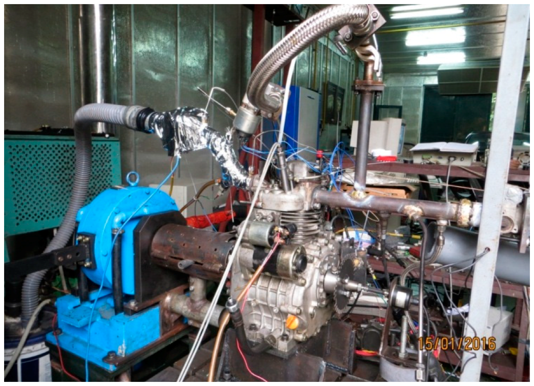
A small, single cylinder, direct injected diesel engine was used to convert to HCCI with n-heptane fuel. Specification of this engine is described in Table 1.
N-heptane (C7H16) is usually used as a reference fuel for octane rating of gasoline fuel, since it has zero points on the octane rating scale. N-heptane has similar properties (Table 2) as diesel fuel; however, due to its low density, this fuel can evaporate easily in the intake manifold that drives its usage as the chosen fuel for HCCI process set-up.
Due to the high latent heat of evaporation, the evaporation process of n-heptane in the intake pipe results in lowering of the intake air temperature, which can negatively affect the auto-ignition process of the fuel-air mixture in the combustion chamber. The heating device located in the intake pipe is, therefore, necessary to ensure the HCCI combustion process.

2.2. Test Equipment

The schematic diagram of the test engine is presented in Figure 1, and a picture of the engine installed in the dynamometer is provided in Figure 2.
As seen in Figure 1, the intake manifold of the test engine was modified for n-heptane fuel, thereby supplying and heating the intake mixture.
The electric heater, located just after the air filter, was used to heat up the intake mixture from a temperature of about 8 °C to a fixed temperature of 25 °C (to compensate for the cooling effect caused by the evaporation process of n-heptane in the intake pipe) for HCCI process set-up and various compression ratio test points. A temperature of 25 °C was identified as the minimum temperature to stably establish the HCCI process at the original compression ratio of 20:1.
An eddy current dynamometer DW16 was used in this test-rig. This dynamometer has 16 kW max. power, 70 Nm max. torque, and 13.000 rpm max. speed, at an accuracy of 0.1%. Fuel consumption was measured by AVL 733S with fuel temperature control based on the principle of gravimetric measurement. The measurement system enables a high-precision fuel-consumption measurement, even at low consumption and short measuring times. The recommended measuring range of this device is up to 150 kg/h with an accuracy of 0.12%. The Bosch lambda sensor LSU 4.9 was used for lambda value measurement. This sensor is a wideband lambda sensor that has a measuring range from 0.65 to ∞. The accuracy at lambda 1 is ±0.007 and the accuracy at lambda 1.7 is ±0.05.

3. Results and Discussion

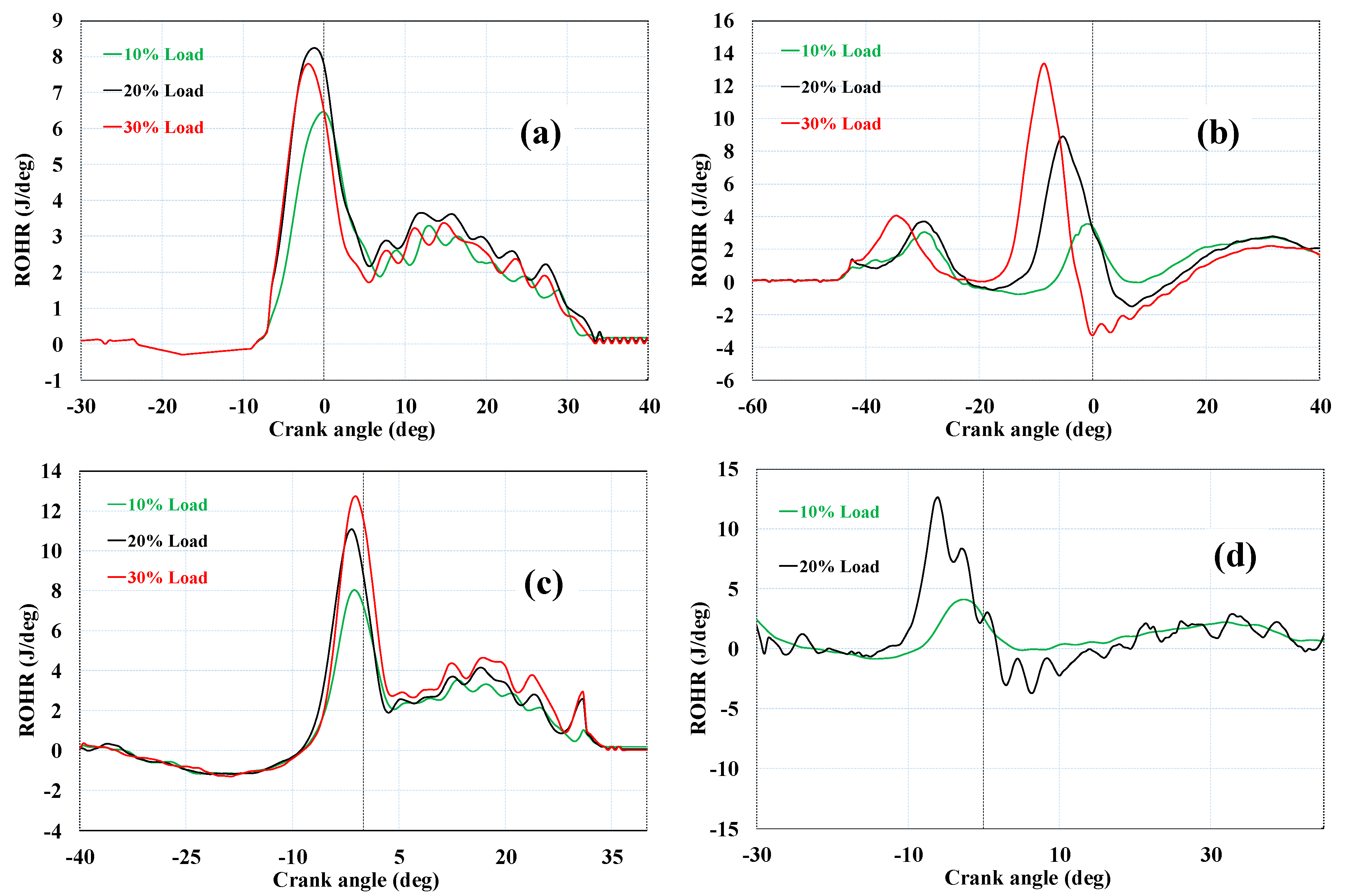
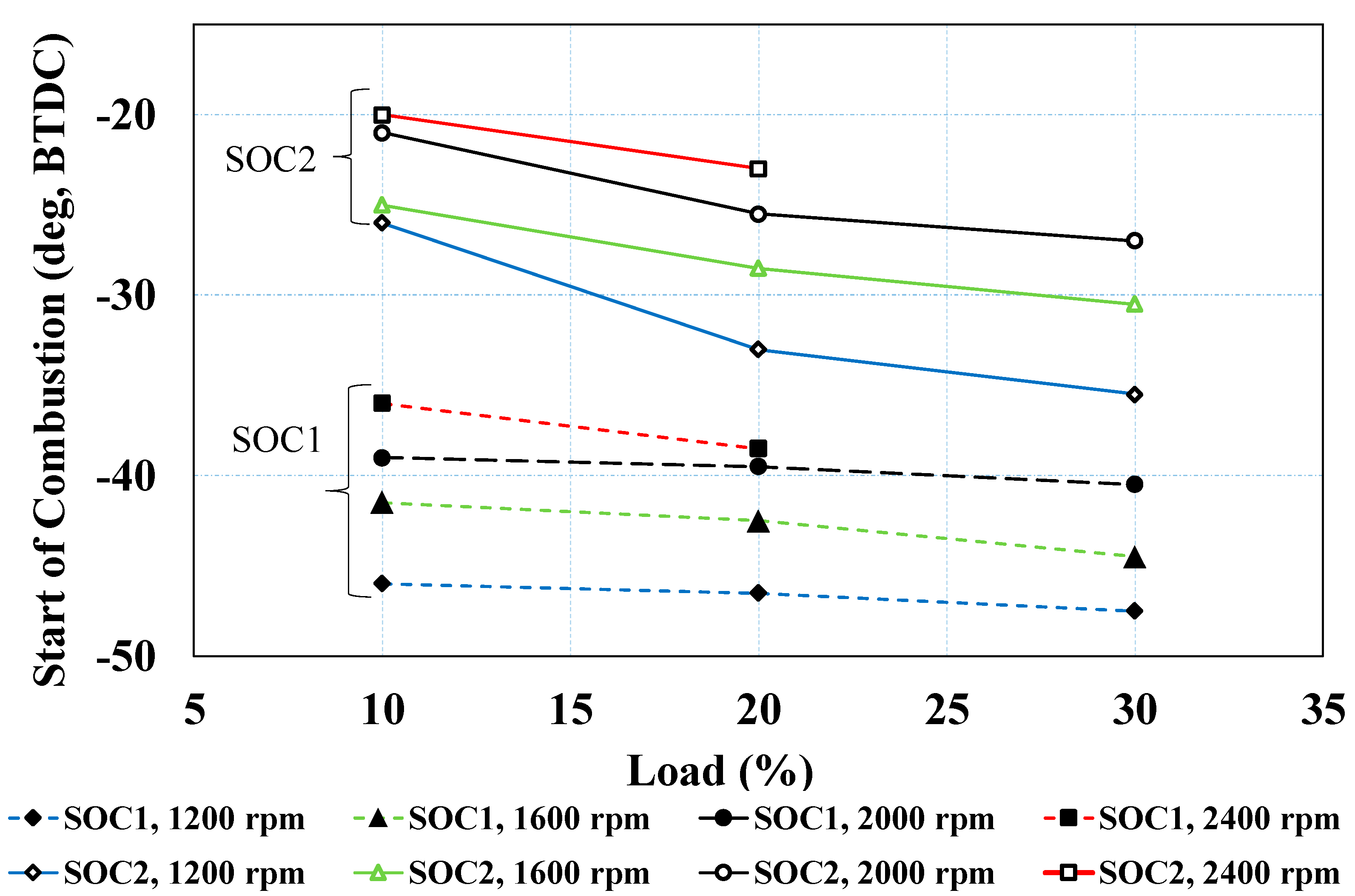
3.1. The Rate of Heat Release (ROHR) and Start of Combustion Calculation

The ROHR is calculated from the average of the continuous 50 measured cycle’s pressure data (p) at each testing condition for every crank angle as follows:
d Q n d φ = γ γ 1 p d V d φ + 1 γ 1 V d p d φ ,  
in which dQn/dϕ is net heat release rate [9]; γ is the ratio of the specific heats, given by γ = Cp/Cv; and dV is the change of volume for the different crank angle.
The curve of ROHR versus crank angle of an HCCI engine has two peaks; the first one indicates low-temperature oxidation (LTO), and the second shows high-temperature oxidation (HTO). Thus, two starts of combustion (SOC) locations are available. In this research, SOC1 and SOC2 were designated as the start of combustion locations for LTO and HTO, respectively. The SOC can be calculated as 10% of the cumulative heat release location, or it can be the derivative of the ROHR versus crank angle.

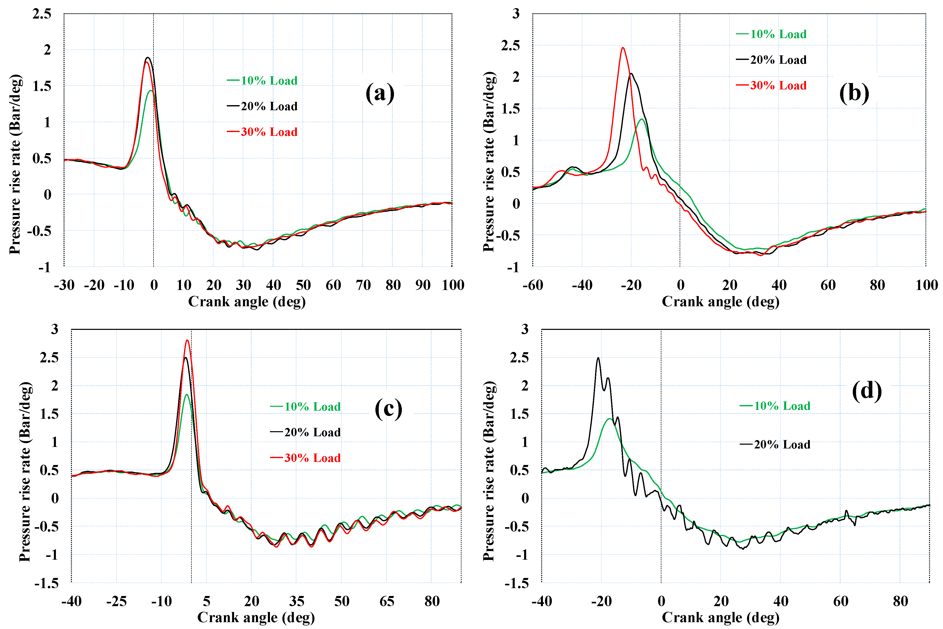
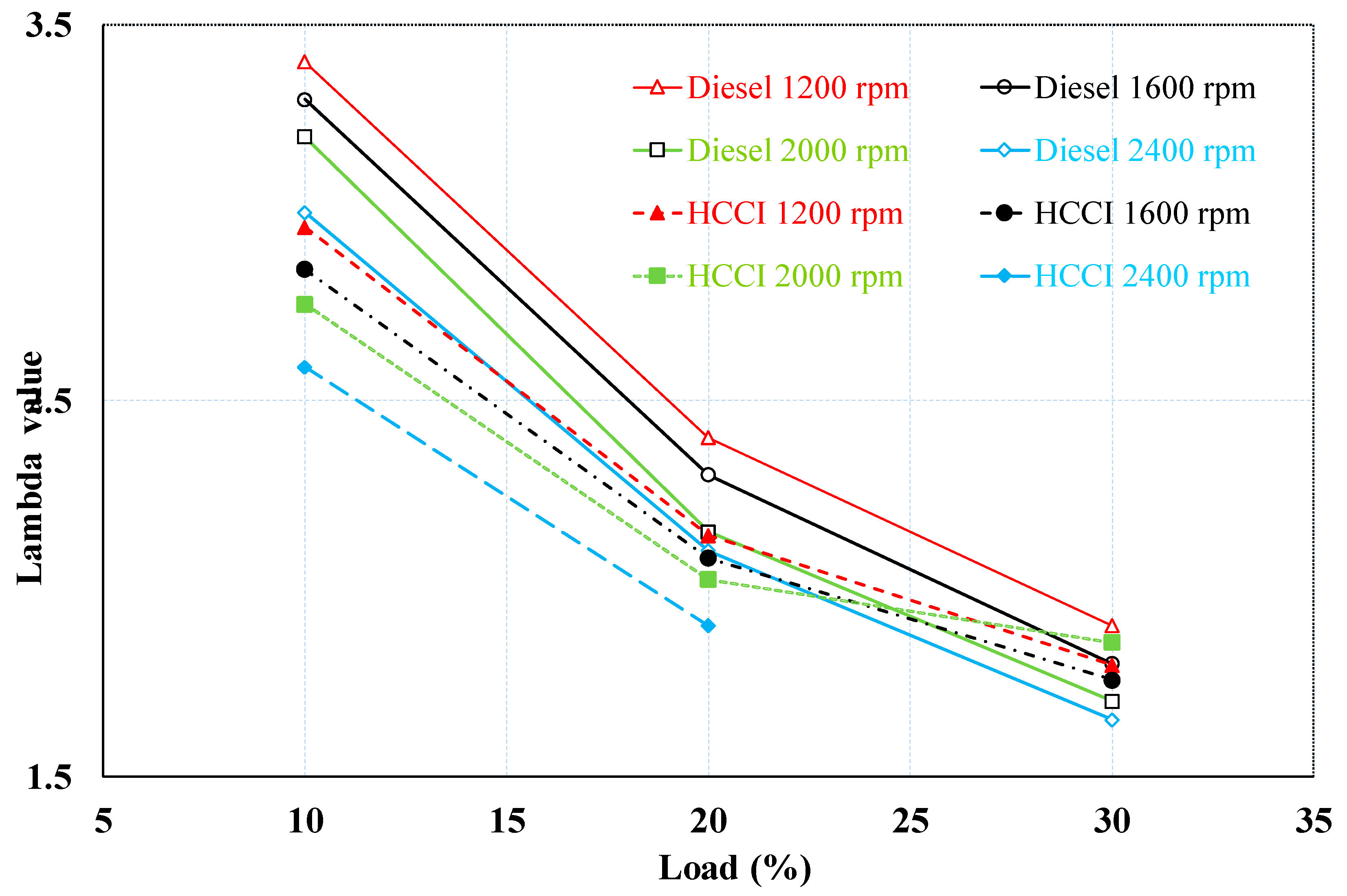
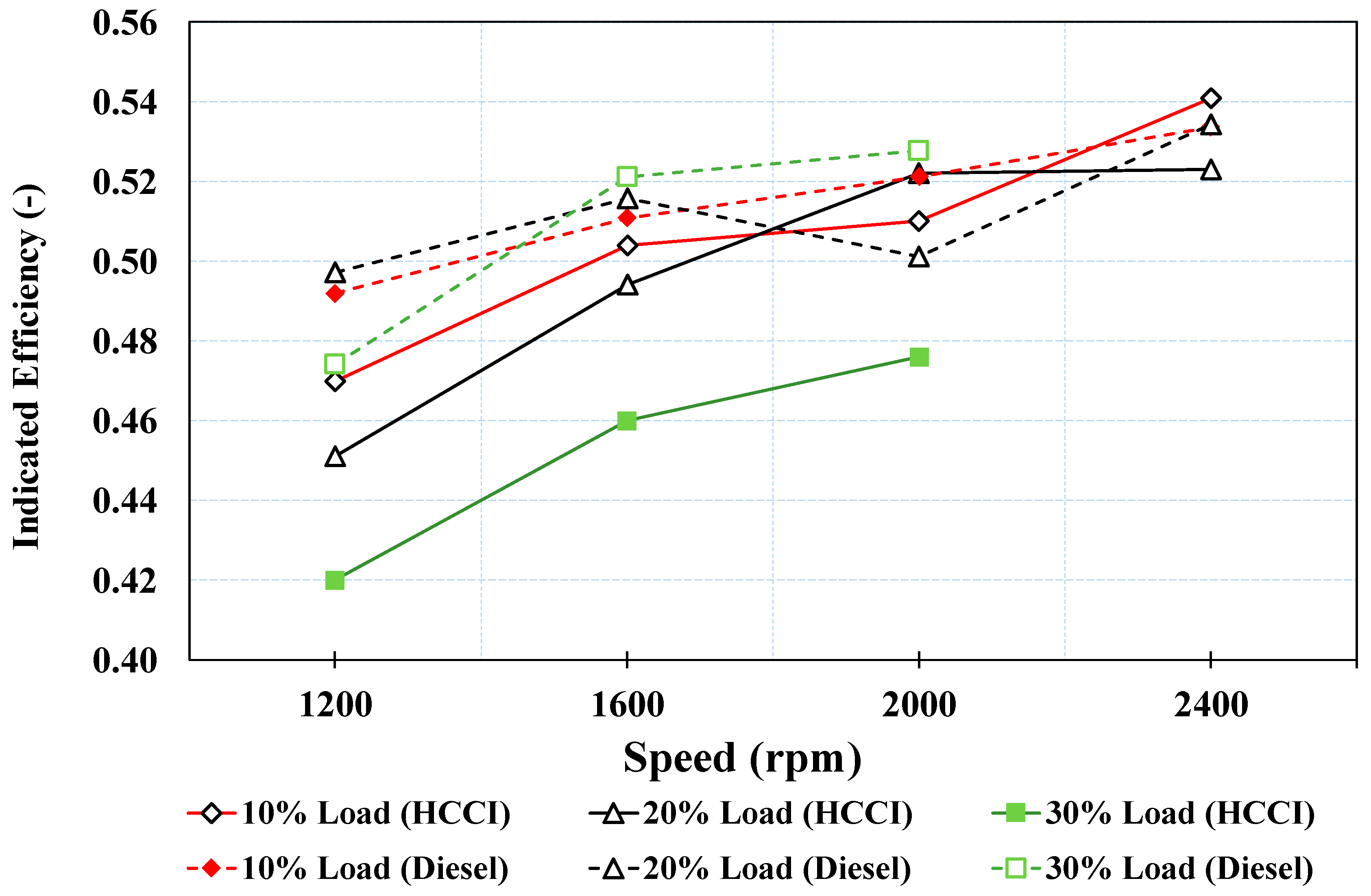
3.2. Combustion Characteristics

To determine the load positions, the original diesel engine was tested at full load condition; the rated torque was at 100% load, which was then used to define the partial loads of the original diesel and HCCI engines. For better comparison, the HCCI engine characteristics were compared with those of the diesel engine at the same load condition.
At the original compression ratio of 20:1, the rates of heat release and pressure of the diesel and the HCCI engines are illustrated in Figure 3. It is can be clearly seen that, at 2000 rpm engine speed, the HCCI process was achieved at 30% load; however, at higher speed (2400 rpm), the HCCI could not be established until 20% load. Higher loads of the HCCI engine could not be reached due to high knocking.
A feature of the diesel engine is that the peaks of ROHC usually appear after TDC, as shown in Figure 3a,c; therefore, the large positive figures of ROHC are after TDC. However, in case of HCCI engine fueled by N-heptane, the maximum ROHR can reach peak value before TDC due to the N-heptane’s characteristics. N-heptane is the straight-chain alkane with the chemical formula C7H16. N-heptane has similar properties to diesel fuel; however, thanks to low density, this fuel can evaporate easily in the intake manifold that drives this fuel to be used as a fuel for HCCI process set-up. In addition, an air-intake heating system was also designed to assist the evaporation process of N-heptane. Furthermore, the cetane number of n-heptane is higher than original diesel. The higher the cetane number of fuel, the shorter the ignition delay; therefore, the large positive figures for ROHR can be observed before top dead center (TDC).
In the diesel engine, the ROHR curves show two peaks; the first indicates the pre-mixed combustion phase, while the latter (often occurring after TDC) plays the mixing-controlled combustion phase. In this HCCI engine, three peaks are observed along the ROHR curves; from left to right, these peaks are the LTO phase, HTO phase, and the HTO phase. The last peak (HTO phase) may have resulted from the late combustion caused by too early, weak ignition. It is also very similar to the mixing-controlled combustion phase in diesel engine combustion. This assumption derives from the negative value of the ROHR just before the TDC in the below graphs of Figure 3. The higher heating temperature at low load conditions and the EGR method may be necessary to merge the second and last peaks as the HTO phase and to retard the combustion. At 30% load, the first and second peaks occurred very early, which might have resulted in lower indicated thermal efficiency due to high compression work. In this case, the EGR is again important to retard the ignition.
Figure 4 shows the pressure rise rate (PRR) profiles of the HCCI and diesel engines at different speeds and loads. Consequently, at loads of 10% and 20%, the PRR of the HCCI engine was lower than that the diesel engine; however, it increased dramatically at a load of 30%. When the PRR profiles of the HCCI reached the value of 2.5 bar/deg, the knocking phenomenon occurring inside the cylinder could be observed. Accordingly, the engine vibrated significantly and the HCCI combustion process was unstable. In addition, the PRR value of the HCCI engine also reached the peak value before the original engine. Furthermore, when increasing the engine speed, the PRR curves moved close to the TDC; however, the maximum value of HRR has a declining trend.
At these low load positions, the lambda values (Figure 5) of the HCCI engine are high but a little lower than those of the diesel engine at all testing speeds and loads. This means more n-heptane fuel was consumed compared with the diesel one. This is reasonable, as, at high and similar compression ratio, HCCI process is probably less efficient than that of a diesel engine. To compensate for this, the HCCI process produced very low NOx and smoke emissions.
The start of combustion of SOC1 and SOC2 was shifted earlier with higher load due to the higher temperature of the mixture, while at the same load, SOC1 and SOC2 were moved closer to the TDC with higher speeds (Figure 6). This means that, at high speed, the combustion was retarded, and thus it is necessary to apply a measure to maintain the start of combustion to achieve high engine-efficiency. In addition, the SOC1 did not change much when the engine load increased from 10% to 30%; however, the second start of combustion occurred significantly earlier as the load increased.
In Figure 7, the indicated efficiency (IE) is plotted, in which it is easy to see that at 30% load, the IE of the HCCI engine is much lower than that at other load regimes. With better starts of combustion, the IE of HCCI engine, at 10% load, with speed ranging from 1200 rpm to 2400 rpm, and at 20% load, with speeds of 1600 rpm and of 2000 rpm, is even slightly higher than that of a diesel engine. Adjustment of the start of combustion at different operating conditions by means of VCR, intake temperature tuning, and EGR is crucial for obtaining high IE of the HCCI engine.

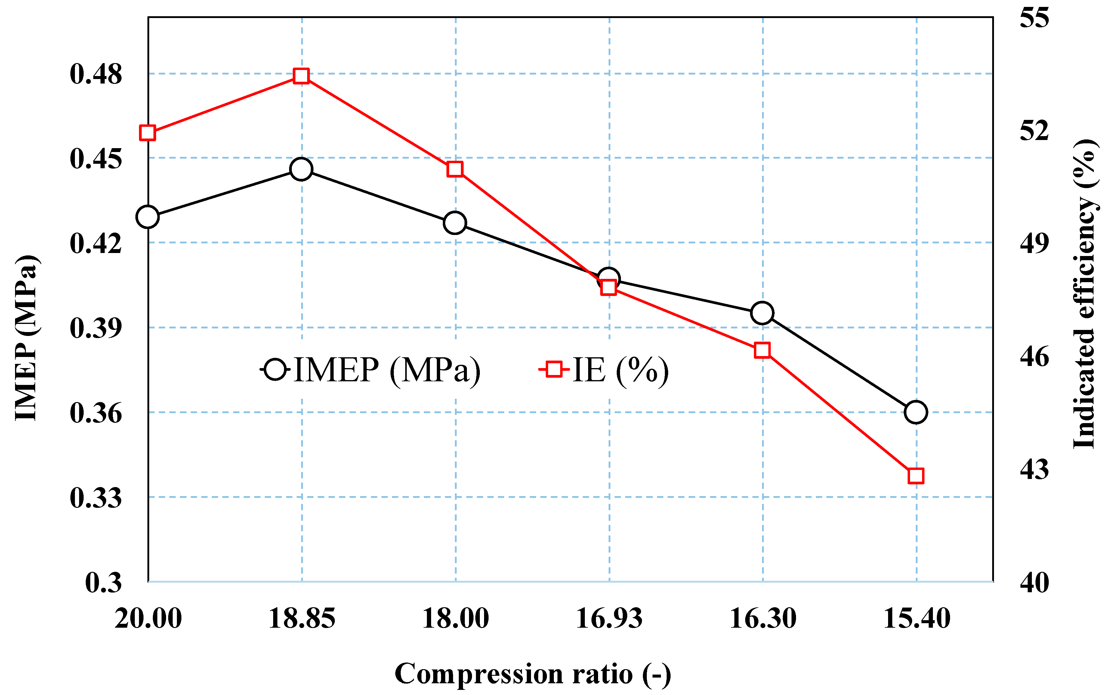
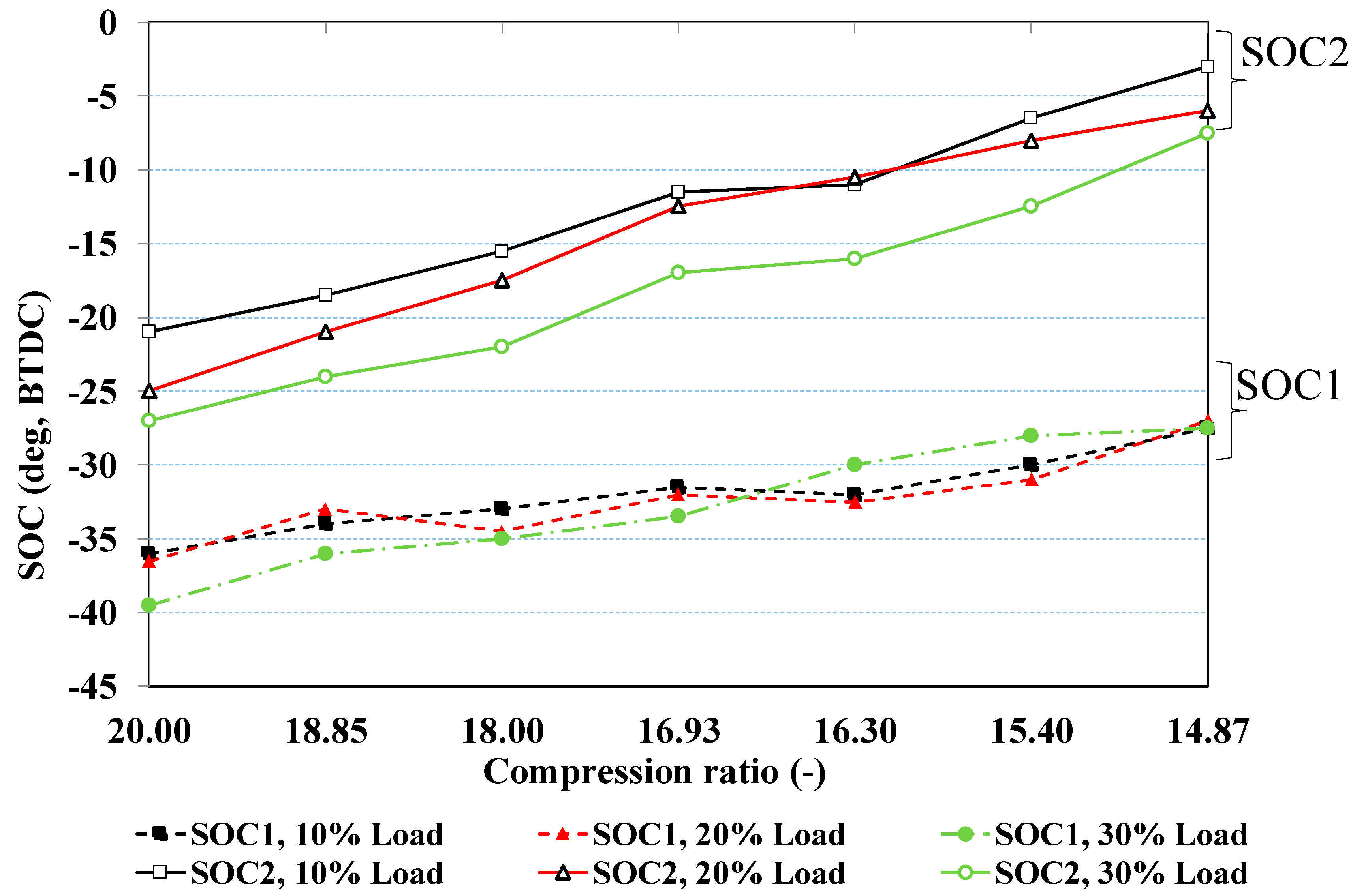
3.3. HCCI Engine Parameters at Different Compression Ratios

Many methods can be applied for extending the HCCI operating regime. In this study, the compression ratio was reduced from 20:1 to 14.87:1 by replacing the thickness of the cylinder gasket. The intake temperature before the intake valve was maintained at 25 °C by electric heater during the various compression ratio test conditions.
The experimental results at 2000 rpm speed show that, despite the compression ratio, the SOC1 was not changed so much at various loads up to 30%, while the start of the second combustion (SOC2) was clearly earlier at high load (Figure 8). This result aligns with that shown in Figure 5. As the compression ratio was reduced from 20:1 to 14.87:1, both absolute values of SOC1 and SOC2 decreased; in other words, the combustion was retarded due to lower pressure and temperature that resulted from lower compression ratio. Thanks to the retarded combustion, the engine vibration was reduced; thus, the engine load and speed were able to increase. The operating range of the HCCI process was extended to 50% and 3200 rpm at low compression ratios, although at high load and speed, the engine vibration signal that resulted from knocking sensor was significantly higher.
The indicated mean effective pressure (IMEP) and the IE versus compression ratio of the diesel and HCCI engine at 30% load and 2000 rpm are plotted in Figure 8. In this research, the IMEP is considered as the average pressure produced inside the cylinder during the operating cycle (it is equal to brake mean effective pressure plus friction mean effective pressure). Meanwhile, IE is defined as the ratio of the work produced per cycle to the amount of fuel energy supplied per cycle that can be released in the combustion process. The research results showed that the best compression ratio for the HCCI engine at this operating condition is 18:1. At this compression ratio, the IMEP and the IE of HCCI engine are even higher than that of a diesel engine (0.446 MPa and 53.43% compared to 0.437 MPa and 50.10% of the diesel engine, respectively).
It was also seen that at a compression ratio of 15.4:1 and lower, the engine could operate very stably at 50% load and high speed. At a low compression ratio (14.87:1), due to late combustion, the IMEP and IE of the engine were very low, as depicted in Figure 9. Thus, the compression ratio of 15.4:1 will be chosen to investigate the next step of application of exhaust gas recirculation.

4. Summary and Conclusions

The HCCI process was set up a single cylinder diesel engine with n-heptane fuel, although at the original compression ratio of 20:1, the operating range of the HCCI process was limited to maximum 2400 rpm and 30% load due to engine knocking. Furthermore, at 30% load, the engine speed was better (no more than 2000 rpm). The operating range of the HCCI process can be extended to 3200 rpm and 50% load by reducing the compression ratio from 20:1 to 14.87:1. At the operating condition of 2000 rpm and 30% load, the best compression ratio, in terms of indicated mean pressure and indicated efficiency, is 18:1. However, at higher loads such as 50% and 2400 rpm speed, the compression ratio of 15.4:1 brought the HCCI process more stability, due to the proper start of the combustion and concomitant low knocking.

Author Contributions

Experimental design was performed by H.K.T. and T.L.A.; fieldwork was conducted by T.L.A.; and statistical analyses were performed by T.L.A., H.K.T. and H.N.X.; T.L.A. and V.N.D. contributed to the writing—review & editing of the paper.

Funding

This research received no external funding.

Acknowledgments

This work was supported by School of Transpiration and Engineering, Hanoi University of Science and Technology.

Conflicts of Interest

The authors declare no conflict of interest.

References

  1. Hassan, A.O.; Abu-Jrai, A.; Al-Muhatseb, A.H.; Jamil, F. Impact of EGR and engine speed on HCCI engine performance and tail pipe emissions. Energy Procedia 2017, 136, 208–212. [Google Scholar] [CrossRef]
  2. Hadia, F.; Wadhah, S.; Ammar, H.; Ahmed, O. Investigation of combined effects of compression ratio and steam injection on performance, combustion and emissions characteristics of HCCI engine. Case Stud. Therm. Eng. 2017, 10, 262–271. [Google Scholar] [CrossRef]
  3. Um, S.; Park, S.W. Numerical Study on Combustion and Emission Characteristics of Homogeneous Charge Compression Ignition Engines Fueled with Biodiesel. Energy Fuels 2010, 24, 916–927. [Google Scholar] [CrossRef]
  4. Yousefi, A.; Gharehghani, A.; Birouk, M. Comparison study on combustion characteristics and emissions of a homogeneous charge compression ignition (HCCI) engine with and without pre-combustion chamber. Energy Convers. Manag. 2015, 100, 232–241. [Google Scholar] [CrossRef]
  5. Nishi, M.; Kanehara, M.; Iida, N. Assessment for innovative combustion on HCCI engine by controlling EGR ratio and engine speed. Appl. Therm. Eng. 2016, 99, 42–60. [Google Scholar] [CrossRef]
  6. Lü, X.C.; Chen, W.; Huang, Z. A fundamental study on the control of the HCCI combustion and emissions by fuel design concept combined with controllable EGR. Part 1. the basic characteristics of HCCI combustion. Fuel 2005, 84, 1074–1083. [Google Scholar] [CrossRef]
  7. Hasan, M.M.; Rahman, M.M.; Kadirgama, K.; Ramasamy, D. Numerical study of engine parameters on combustion and performance characteristics in an n-heptane fueled HCCI engine. Appl. Therm. Eng. 2018, 128, 1464–1475. [Google Scholar] [CrossRef]
  8. Machrafi, H.; Cavadiasa, S. An experimental and numerical analysis of the influence of the inlet temperature, equivalence ratio and compression ratio on the HCCI auto-ignition process of Primary Reference Fuels in an engine. Fuel Process. Technol. 2008, 89, 1218–1226. [Google Scholar] [CrossRef] [Green Version]
  9. Maurya, R.K.; Agarwal, A.K. Experimental investigations of performance, combustion and emission characteristics of ethanol and methanol fueled HCCI engine. Fuel Process. Technol. 2014, 126, 38–48. [Google Scholar] [CrossRef]
  10. Bhaduri, S.; Jeanmart, H.; Contino, F. Tar Tolerant HCCI Engine Fuelled with Biomass Syngas: Combustion Control Through EGR. Energy Procedia 2017, 105, 1764–1770. [Google Scholar] [CrossRef]
  11. Nobakht, A.Y.; Khoshbakhi Saray, R.; Rahimi, A. A parametric study on natural gas fueled HCCI combustion engine using a multi-zone combustion model. Fuel 2011, 90, 1508–1514. [Google Scholar] [CrossRef]
  12. Ravi, N.; Liao, H.H.; Jungkunz, A.F.; Widd, A.; Gerdes, J.C. Model predictive control of HCCI using variable valve actuation and fuel injection. Control Eng. Pract. 2012, 20, 421–430. [Google Scholar] [CrossRef]
  13. Kwon, O.S.; Lim, O.T. Effect of boost pressure on thermal stratification in HCCI engine using the multi-zone model. J. Mech. Sci. Technol. 2010, 24, 399–406. [Google Scholar] [CrossRef]
  14. Ge, J.C.; Kim, M.S.; Yoon, S.K.; Choi, N.J. Effects of pilot injection timing and egr on combustion, performance and exhaust emissions in a common rail diesel engine fueled with a canola oil biodiesel-diesel blend. Energies 2015, 8, 7312–7325. [Google Scholar] [CrossRef]
  15. Reitz, R.D.; Duraisamy, G. Review of high efficiency and clean reactivity controlled compression ignition (RCCI) combustion in internal combustion engines. Prog. Energy Combust. Sci. 2015, 46, 12–71. [Google Scholar] [CrossRef]
  16. Blomberg, C.K.; Wright, Y.M.; Boulouchos, K. A phenomenological HCCI combustion model in 0D and 3D-CFD. Fuel 2018, 226, 365–380. [Google Scholar] [CrossRef]
  17. Coskun, G.; Soyhan, H.S.; Demir, U.; Turkcan, A.; Ozsezen, A.N.; Canakci, M. Influences of second injection variations on combustion and emissions of an HCCI-DI engine: Experiments and CFD modelling. Fuel 2014, 136, 287–294. [Google Scholar] [CrossRef]
  18. Poorghasemi, K.; Saray, R.K.; Bahlouli, K.; Zehni, A. 3D CFD simulation of a natural gas fueled HCCI engine with employing a reduced mechanism. Fuel 2016, 182, 816–830. [Google Scholar] [CrossRef]
Figure 1. Schematic diagram of the homogeneous charge compression ignition (HCCI) engine test-rig.
Sustainability 10 03878 g001
Figure 2. HCCI engine installed in the chassis dynamometer.
Sustainability 10 03878 g002
Figure 3. Rate of Heat Release (ROHR) of the HCCI and diesel engines at different speeds and loads, (a) Diesel engine—2000 rpm, (b) HCCI engine—2000 rpm, (c) Diesel engine—2400 rpm, and (d) HCCI engine—2400 rpm.
Sustainability 10 03878 g003
Figure 4. Pressure rise rate of HCCI and diesel engines at different speeds and loads: (a) diesel engine—2000 rpm, (b) HCCI engine—2000 rpm, (c) diesel engine—2400 rpm, and (d) HCCI engine—2400 rpm.
Sustainability 10 03878 g004
Figure 5. Lambda values of the diesel and the HCCI engines at different speeds and loads.
Sustainability 10 03878 g005
Figure 6. Start of combustion of the HCCI engine at various operating regimes.
Sustainability 10 03878 g006
Figure 7. Indicated efficiency (IE) at various speeds and loads.
Sustainability 10 03878 g007
Figure 8. Start of combustion of the HCCI engine versus compression ratios at 2000 rpm, with different loads.
Sustainability 10 03878 g008
Figure 9. IMEP and indicated efficiency (IE) versus compression ratios at 2000 rpm, at 30% load.
Sustainability 10 03878 g009
Table 1. Specification of the test diesel engine.
ParameterValue
Displaced volume273 cm3
Type of engineDirect Injection, naturally aspirated
Stroke57 mm
Bore78 mm
Compression ratio20:1
Number of valves2
Rated power/speed4.4 kW/3600 rpm
Max. Torque/speed13 Nm/2000 rpm
Table 2. Properties of n-heptane fuel.
PropertiesUnitTest MethodValue
Viscosity at 40 °Cmm2/sASTM D445-000.567
Flash point°CASTM D93-02−4
Density at 15 °Cg/cm3ASTM D1298-050.68873
RVP at 37.8 °CPSIGASTM D323-991.8
Heating valuekcal/kgASTM D240-0211,125
n-heptan content%GC/MS97.5
Cetane number--56
A/F ratio--15.132
Latent heat of evaporationkJ/kg-316.6

