Mechanical Tests on Innovative BIPV Façade Components for Energy, Seismic, and Aesthetic Renovation of High-Rise Buildings


1
Dipartimento di Architettura, Scuola Politecnica, Università degli Studi di Palermo, 90128 Palermo Italy
2
SBskin, Smart Building Skin s.r.l., 90128 Palermo, Italy
Sustainability 2018, 10(12), 4523; https://doi.org/10.3390/su10124523
Submission received: 30 September 2018
/
Revised: 23 November 2018
/
Accepted: 26 November 2018
/
Published: 30 November 2018
(This article belongs to the Special Issue Energy and Seismic Renovation Strategies for Sustainable Cities)
Abstract
:The paper shows the results of mechanical tests carried out on prototypes of a new Building Integrated Photovoltaic (BIPV) component developed by the author and SBskin Smart Building Skin s.r.l. This patented innovative component is able to merge structural function, insulation proprieties, and production of clean energy for retrofit actions and/or the construction of translucent façades in high-rise buildings located in different climatic contexts. Due to colored PV cells integrated into 3 Dimensional (3D) glass components and the dry-assembly system used for assembling them into precast and pre-stressed panels, an easy and creative customization of the product is allowed. Green energy production, safety, and energy efficiency of buildings can be assured in accordance with the environmental conditions and users’ needs. The pre-stressing force used to improve the mechanical resistance of the panel toward horizontal forces due to winds and earthquakes guarantees the construction of secure translucent and active building envelopes. The paper summarizes the features of this innovative and patented BIPV product by focusing on its mechanical behavior. Laboratory tests are described and commented for underlining the benefits derived from the use of the dry-assembly system and of the supporting structure made of plastic for the construction of the panels. Bending and breaking strength tests have been carried out on two sq.m of panel prototypes, which have been dry-assembled through a supporting structure made of Polypropylene (PP) in order to compare the results with the theoretical calculations derived from the Finite Element (FE) simulations. Cyclic mechanical testing of the panel has been also carried out to verify its behavior under cyclic loading and understanding its ability to counteract the actions of the wind and earthquake.
1. Introduction
SBskin. Smart Building Skin s.r.l. (www.sbskin.it) is an innovative start-up and academic spin off of the University of Palermo co-founded by the author (the CEO) with the aim to give a small and ambitious contribution to make our planet greener and our buildings sustainable and beautiful at the same time. By spreading the use of Renewable Energy Sources (RESs) and, in particular, of third generation PV technologies as well as by improving the building sector in Europe and abroad through the use of an innovative solution for the construction of translucent, active, and safe building envelopes even in high-rise buildings.
Buildings account for about 40% of the European Union’s and the world’s CO2 emissions largely due to the operations of air conditioning, heating, and electricity systems [1]. The “2020 Climate and Energy Package” and the “2030 Climate and Energy Framework” [2] are European key actions that aim to cut the greenhouse gas emission by 20% for 2020 and by 40% for 2030 based on 1990 levels. Furthermore, the EU target is to bring the share of renewables in the EU area to 20% of the total energy in 2020 and 27% in 2030. In this scenario, innovative BIPV solutions that increase thermal and energy autonomy of buildings in urban areas (by guaranteeing less greenhouse gas emissions) and produce solar energy (by guaranteeing a bigger share of energy from renewables) are strongly sought after. The use of RESs and the optimization of the building performance is getting critical for the mitigation of climate change for “ethical,” environmental reasons and for economic effects on the building management costs.
Climate change is an environmental, social, and political challenge that can be won by transforming buildings from polluters into energy producers through the exploitation of photovoltaic energy. The innovative BIPV product designed by the author and SBskin company is aligned with the white paper “Roadmap to a Resource Efficient Europe” [3], adopted by the Commission in 2011. The paper defines clear goals to be reached by 2050 especially when considering one of the white paper’s sections: “Improved Buildings” (No. 5.2). Actually it consists of multifunctional 3D glass sub-components totally dry assembled into precast and pre-stressed panels useful for the construction of the building envelope [4]. They act as insulation and use photovoltaic cells to generate their own electricity [5]. One big plus is that the panels come in a range of translucent colors and designs and they can be used to create some very colorful buildings.
Today, one of the recurrent problem is that often reducing the energy consumption of buildings comes at the expense of their architectural and structural quality. Photovoltaic is still seen by many as an “eyesore” technology and quite hard to get architecturally integrated. As a result, in recent years, greater attention has been addressed toward novel BIPV technologies consisting of multifunctional products aimed at the integrating photovoltaics in the architectural cladding. As a consequence, the BIPV market is leaving a “niche condition” by reaching a bigger market share and more users every year. Technology has still many economic, technical, and procedural weaknesses such as higher operating temperature due to the lack of the airflow system between the module and host structure. BIPV solutions especially for the facade suffer an overheating at higher temperature with a sensible reduction of performance in terms of conversion efficiency and degradation. These problems are particularly considerable with silicon solar cells integrated with float glass. New BIPV Technologies (e.g., Dye-sensitized Solar Cell—DSC/Organic Photovoltaics—OPV), which are more sustainable even if less efficient in terms of energy production, are spreading on the market, but they usually need different sub-components to be installed in buildings [6].
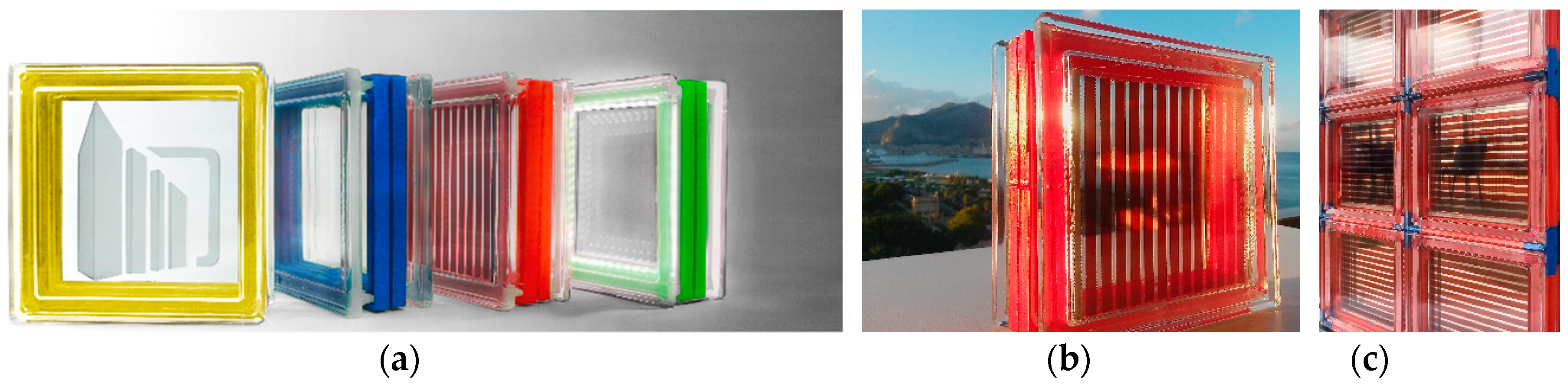
SBskin multifunctional building panels made of 3D glass sub-components integrated with third generation solar cells have been widely described in previous papers [7,8,9]. They are able to compete with active flat glass products already existing in the BIPV market in terms of both design integration and energy/mechanical performance. Therefore, they can be used for the construction of sustainable building envelopes in high-rise buildings and for the retrofit of multistory buildings located in seismic areas. They are able to guarantee different levels of thermal transmittance, according to the climatic conditions, which allows it to reach the benchmark U value of 1.0 W/sqmK [10] thanks to a patented “thermal belt” made of plastic (Figure 1a). The 3D glass sub-components are also integrated with solar cells that are transparent, colored (Figure 1b), and able to produce clean energy even under a cloudy sky without requiring any specific installation conditions. They are dry-assembled into panels according to a patented solution that takes advantage of a mono-directional pre-stressing force in order to allow panels to resist against horizontal forces due to wind and earthquakes (Figure 1c).
Aesthetic, Efficiency, Safety, CO2 reduction, Maintenance, and Assembly Costs are the main peculiarities of this innovative BIPV product that can be easily managed by designers involved in new building construction and/or in renovation actions.
Actually, the huge old building stock made of glass blocks is currently needed for substantial energy and structural renovation and/or fully replacement: by using this innovative product, designers and builders can easily optimize the energy performance of the transparent/translucent components of buildings by enhancing their aesthetics at competitive costs. Furthermore, the product makes localization choices to be released from exposure difficulties regarding the daytime and weather conditions since it demonstrates good performances and efficiency in “diffuse light” conditions. In other works, the performance behavior of DSCs integrated into 3D glass components have been investigated [7,8].
Third generation of solar cells show high efficiency performance in indoor conditions [11] so SBskin panels can be used as internal partitions in order to color and liven up inner buildings as hospital and health structures, e.g., this feature represents an added value in the field of BIPV products on the market while such versatility leads to a realistic appeal for renovation/retrofit and construction of new buildings.
The SBskin panel is a highly customizable product designed for going beyond BIPV aesthetic limits. Thanks to the particular features of third generation solar cells—which are printable in different colors and transparency—the 3D glass sub-components can be assembled in many colored configurations by exploiting the different colors of plastic profiles used for assembling the panel, so they are adaptable for several building typologies and structures. These features offer a huge versatility for satisfying the customer’s needs and the architectural visions of designers that can easily manage aesthetic versatility from the early stage of the building design process [12] (Figure 2).
The benefits derived from the use of this innovative BIPV façade component for improving the energy efficiency of existing buildings have been already evaluated and described in another published paper [13] by simulating its installation for the energy retrofit of an existing office building in Palermo (Figure 3a). According to literature, dye-sensitized solar cells are “bio-compatible,” transparent, colored, and was able to produce clean energy even when they are not correctly oriented and in diffuse light conditions [14]. Thanks to these peculiar characteristics, they can be installed even in a vertical position toward the north and, despite their lower conversion efficiency, if compared with crystalline silicon technology when the installed power is the same, they are able to produce yearly from 20% to 60% more energy in real operating conditions [15]. In case of the Regional Department of Energy and Services of public utility of Sicily, the four façades of building have been used for installing SBskin panels and a peak power equal to 185 kW was obtained. The production of clean electricity was estimated into 115 MWh/year and, thanks to the solar protection provided by the solar cells, a 20%–29% reduction of the HVAC-related energy consumption was observed (Figure 3b). This translates into a significant reduction of building energy management costs and into a huge reduction of buildings’ CO2 emissions. Actually, it has been calculated that each 3D glass sub-components can contribute to reduce 1.38 kg of CO2 (38 kg/sqm) every year in the climatic context of Palermo.
As previously mentioned, SBskin 3D glass sub-components, DSC integrated, are dry-assembled into panels through plastic molded profiles provided with holes for the passage of stiffening steel bars positioned along the prevailing dimension of panel (Figure 4a). They work as a supporting/separation structure that allow to have only 2 mm joints among the 3D glass components. Thanks to the application of the mono-directional pre-stressing force, they are able to resist against horizontal forces due to wind and earthquakes. Different laboratory and numerical tests have been already done in order to verify the relapses on the mechanical performance of SBskin panel due to different dimensions and/or materials of its sub-components DSC-integrated glass blocks [16] and plastic profiles [17,18]. Prototypes of the panel have been tested by considering loading conditions equal to those of a panel positioned at 45 m of highness and by considering the solicitations in accordance to Italian Regulation for Building Construction [19].
The patented dry-assembly system compared to the wet assembly system traditionally used for assembling glass blocks and based on mortar use (Figure 4b,c) significantly reduces the time, cost of panel construction, and allow the connection of it to the load-bearing structure of buildings simply by using mechanical connections.
2. Laboratory Tests on Prototypes of Dry-Assembled Panels with a PP Supporting Structure
The results of previous numerical simulations carried out on panels made by using different plastics materials and/or different dimensions of 3D glass sub-components (33 × 33 × 12 cm instead of 19 × 19 × 8 cm that usually corresponds to a “standard” glass block) have been already discussed in other research studies particularly in References [16,17].
In this section, the results of laboratory tests carried out for the assessment of mechanical behavior of 2 sq.m of panel, dry-assembled through a supporting structure made of Polypropylene (PP) are reported. Bending and breaking strength tests have been carried out in order to compare the results with the theoretical calculations derived from the Finite Element (FE) simulations already carried out by using the commercial software Straus7® and COMSOL Multiphysics®.
Cyclic mechanical testing of the panel has been also carried out for verifying its behavior under cyclic loading and understanding its ability to counteract the actions of the wind and earthquakes.
The tested panels consist of 50 19 × 19 × 8 cm 3D glass sub-components assembled through 115 shaped profiles and 66 special elements in the shape of different crosses made of PP. The resulting prototypes are 96 cm wide, 196 cm tall, and 8 cm thick (Figure 5a). The panels correspond to a façade module positioned at 45–48 m of highness where 12 stainless steel, 8 mm cables subjected to a pre-stressing force and hidden into vertical profiles support its structure.
2.1. Bending Tests
The mechanical scheme adopted for simulating the wind action on façade panels and for testing the panels in the Laboratory of the Department of Civil, Environmental, Aerospace, Materials Engineering at the University of Palermo is that of a beam supported at both ends (A, B) (Figure 5b, ↑). A constant compressive pressure acting axially along the panels has been considered. Therefore, a horizontal constant distributed load q has been considered in the model.
The load application area corresponds to the dimension of water beds used for the tests and is equal to 193 × 70 cm (Figure 5b, ↓).
The water beds have been gradually filled during the tests (Figure 6). The value of wind pressure was calculated on the basis of a wind intensity equal to 1338 N/m and a wind speed of 28 m/s, which results in a pressure, according to the Italian regulation DM 14 January 2018, which is also known as NTC 2008 [19].
This value has been boosted in order to take into account a safety factor equal to 1.3, so:
Conversely, the value of pre-compression was calculated considering a no-tensile element subjected to the maximum bending arising from the wind pressure action. This calculated value results are equal to:
The tightening torque to apply for pre-stressing the steel bars has been calculated by the equation below.
where:
is the coefficient related to the material and the surface conditions, which is usually equal to 0.20,
ϕ is the diameter of the steel bars equal to 8 mm,
N/12 is the pre-stressing force to apply for each steel bar. Therefore:
The tightening torque has been increased to 10 N for staying in safety conditions.
During the tests, the pre-stressed panels have been positioned and equipped with micrometer dial gauges and gradually loaded through the filling of water beds, which is shown in Figure 6 (see the four pictures ↓). During one of the first bending tests, a wooden board and 18 steel weights of round shape (as shown in the four pictures ↑ of Figure 6) were positioned above four smaller waterbeds.
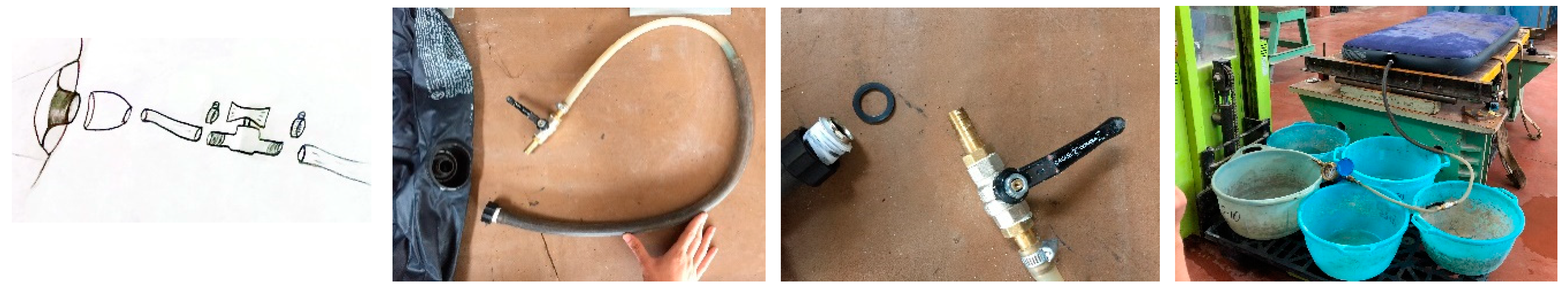
A liter counter, specific seals, and faucets positioned in the pipes that come out from the water beds have been used to better manage the loading/unloading phases (Figure 7).
The loading phase has been carried out gradually and every step the value of panel lowering has been recorded by micrometer deal gauges. The liters of water pumped in the water-beds have been counted through a special count-liters. By way of example, the load steps adopted for two of the laboratory tests carried out on the panels are described in Table 1. In order to acquire detailed data from the micrometer dial gauges installed, some loads have been applied following micro-steps.
Panel remained under load for 12–15 h.
The unloading phases have been also recorded. They gradually happened, as reported in the following Table 2.
2.2. Breaking Strength Tests
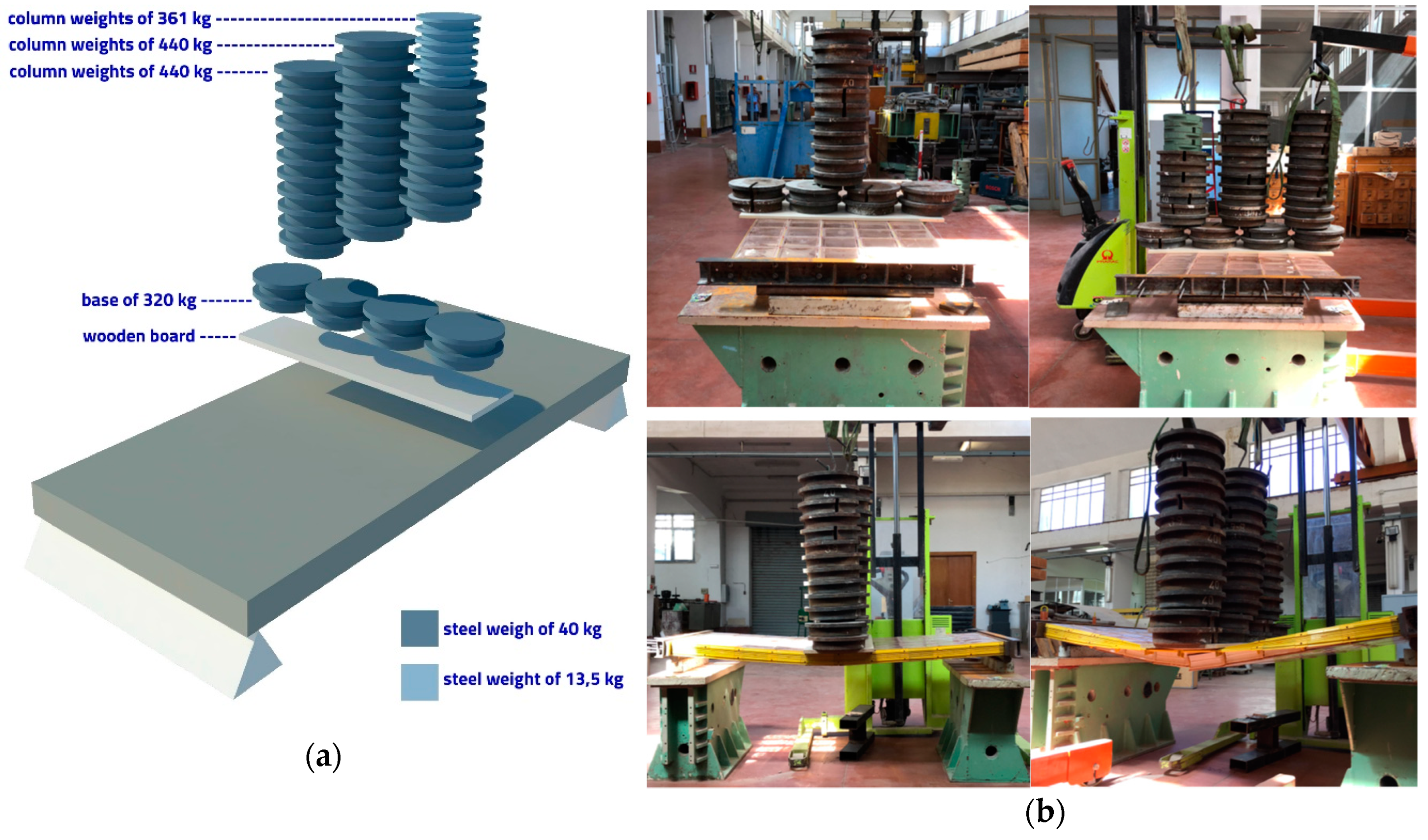
The mechanical scheme adopted for testing the panel and verify its behavior in order to find the breaking strength is that of a beam supported at both ends with a concentrated load considered acting in its centerline. This scheme has been adopted to overcome the limits due to the laboratory equipment. During the tests, the pre-stressed panels have been positioned and gradually loaded through round shaped steel weights positioned on a wooden board in order to avoid their contact with glass blocks (Figure 8). The panel has not been equipped with micrometer dial gauges for avoiding their eventual damage following the panel breaking that happened under a load equal to 1561 kg.
The loading phase has been carried out gradually for taking into account the particular test mechanism. During the test, all panel sub-components have been constantly checking for verifying their integrity. The load steps adopted according to the available equipment in the laboratory are described in Table 3 and they are put in relation to the damages registered for the different subcomponents of panel. All sub-components have been numbered, analyzed, and classified by considering three levels of damage: intact, plasticized, broken (Figure 9).
2.3. Cyclic Mechanical Testing
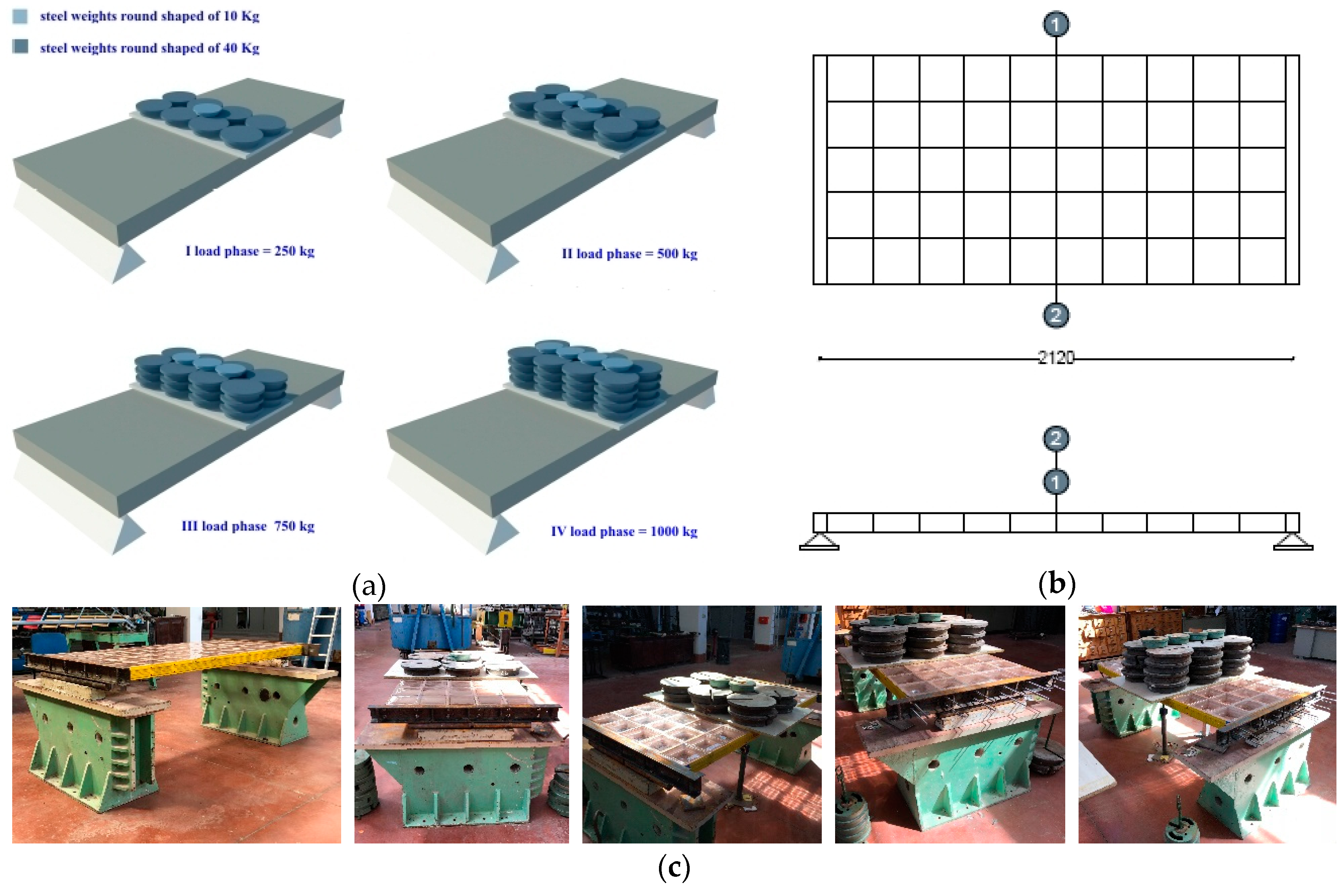
Tests under cyclic actions without inversion of the sign have been carried out in order to simulate the horizontal actions due to wind and earthquakes on a façade panel positioned at 45 m of highness. The mechanical scheme adopted for testing the panel is the same of the breaking strength tests that consists of a beam supported at both ends with a force applied in its centerline (Figure 10a). The value of concentrated load has been calculated by considering equal the values of the bending moment in both mechanical schemes related to a beam with a distributed load and with a concentrated force applied in the centerline and by solving the following equation
where:
is the distributed load.
P is the concentrated force. Therefore, the following is true.
According to the dimension of panel, the previous equation becomes Equation (8) below.
Micrometer dial gauges have been positioned as shown below (Figure 10b) in order to register the displacements of the panel under load.
The load cycles have been determined in accordance with the results of the breaking tests. The breaking values obtained from the tests are between 1300–1561 Kg. Therefore, taking into account the risk of eventual damages of panel sub-components not registered during previous tests, four load cycles of 250 kg each have been executed in order to complete the test by reaching a total load on the panel equal to 1000 kg and succeeding to maintain its integrity. The loads have been positioned manually. In Table 4, the sequence of load cycles are reported.
At the end of each cycle, the displacements of the panel and the pre-stressing force of the panel steel bars have been registered and checked. The displacements of the panel have been registered for each cycle after both the load phase (at the load peak) and the unloading phase by waiting for about 15 minutes in order to allow the adjustment of the panel. After the test and the panel disassembly, all the sub-components were examined in detail in order to understand the influence of the cyclic load on their behavior.
3. Results and Discussion
Through the installed micrometer dial gauges, the lowering values of the panel have been recorded in relation to the load gradually applied during the bending tests and the following graphs have been elaborated upon. In the first test described in Section 2.1, the dial gauges positioned in the middle of the panel (C2, C4) and those positioned at 1/6 and 5/6 of the panel length (C1, C3) have shown the trend reported in Figure 11.
The graphs show the good response of the PP supporting structure that allow the panel to resist to 400 Kg/sqm without any kind of deformation of sub-components and perfectly in line with the results obtained from numerical simulations discussed in previous research papers already cited [16,17] in which, through the use of COMSOL Multiphysics® software (Structural Mechanics Module) [20], linear static analyses have been carried out with the aim to select the best performing material composing the structural profiles of the panel.
As a result of a second bending test described in Section 2.1, the following graphs related to the 6 micrometer dial gauges installed on the panel have been elaborated upon (Figure 12).
The graphs confirm the good performance of the panel under a distributed load that enable its use for translucent floors and not only for building façades. Actually, all the micrometer dial gauges have returned almost to the original values by confirming the elastic behavior of the dry assembled, pre-stressed 3D glass panel.
A comparison between the theoretical and experimental panel deflections has demonstrated the good response of the panel under load in line with the expected displacements that allow the panel to remain in safe conditions. Without describing in detail the calculations for processing the equation of the elastic line, in Figure 13, one of the comparisons between theoretical and experimental deflections of the panel (carried out for each test) is reported. The theoretical deformation has been obtained by interpolating the displacements derived from the equation of the elastic line. The experimental deformation has been obtained by interpolating the displacements measured by the micrometer dial gauges positioned along the panel at 1/6, 1/2 and 5/6 of its length.
Regarding the breaking tests, the maximum value reached under load has been equal to 1561 Kg even if, under a load equal to 1200 Kg, the panel started to deflate itself plastically but without any breaking of panel subcomponents. The breaking of the panels happened not immediately but after 5 min of load application and it consisted of a differential failure of glass blocks positioned in the middle of panel, the twist of plastic profiles positioned in the panel long sides due to the plasticisation of steel bars (Figure 14a), and the explosion during only one test carried out in Lab. of a glass block (Figure 14b) adjacent to the C-shaped steel profile positioned along one of the panel short sides that represent the zone of greater influence of the pre-stressing force applied to the stiffening steel bars hidden into the panel.
The results of cyclic mechanical testing are shown in Figure 15. The values of micrometer dial gauges have been registered after 15” of the application of load. The same time has been expected for registering the value after each unloading phase. The results of the tests have demonstrated that SBskin panel made of 3D glass sub-components, totally dry assembled, is able to resist horizontal forces due to wind and earthquakes (calculated considering a panel positioned at 45 m of highness and in accordance with the Italian Regulation for Building Construction) without any significant damage that can compromise the safety of people.
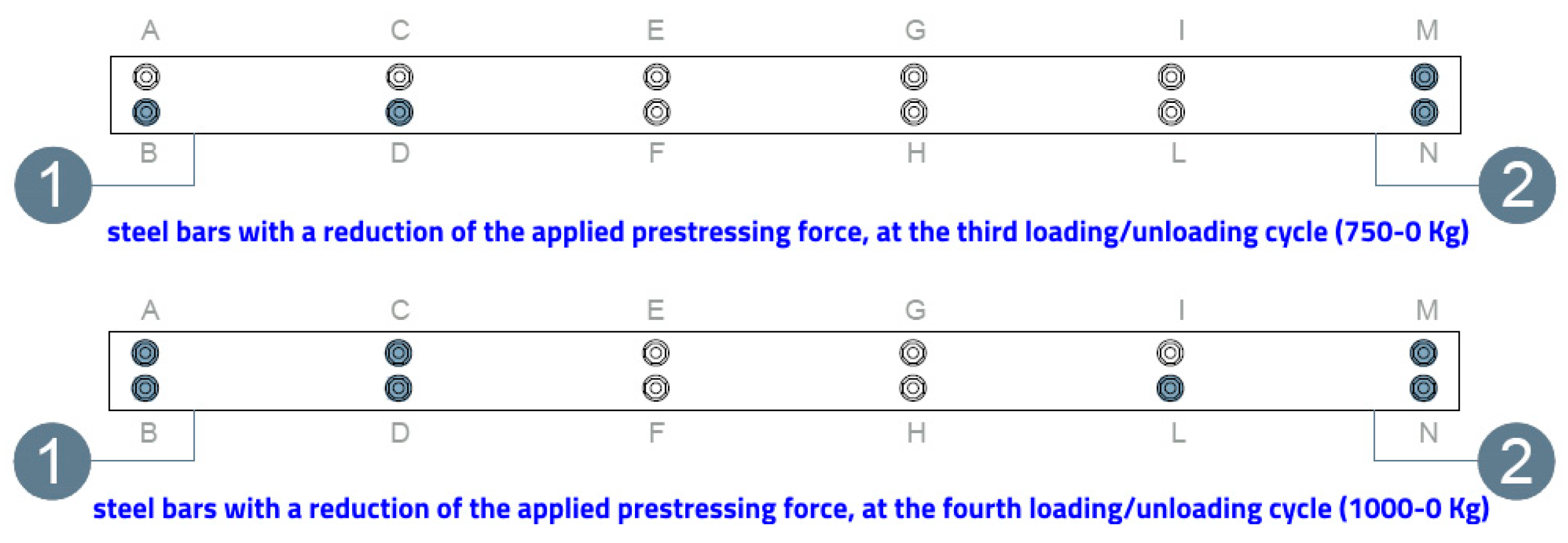
The results of cyclic mechanical testing allowed us to investigate the ability of the panel to maintain the applied pre-stressing force under cyclic loading conditions, which gradually increased. A reduction of the pre-stressing force value has been registered under a load equal to 750 Kg in correspondence of the steel bars positioned in the longer sides of the panel (Figure 16).
Nevertheless, thanks to the monodirectional pre-stressing force applied to steel bars hidden into the PP profiles (positioned among the 3D glass sub-components of panel), all sub-components remain under load in their position for a long time by allowing people to run away during, e.g., a seismic action. However, more laboratory tests will have to be carried out in the future to quantify in detail the time before the panel collapses in accordance to a different entity of mechanic and/or dynamic solicitations.
4. Conclusions
As discussed in § 3, the laboratory tests allowed us to understand the problems related to the configuration of the panel, the behavior of its sub-components under different loading conditions, and the effectiveness of the pre-stressing force. They have confirmed the possibility to use PP for the construction of supporting/separating the structure of the panel and the validity of the mono-directional pre-stressing force used in order to increase the mechanical resistance of multifunctional, translucent panels made of glass blocks. The dry-assembly system confers high mechanical performance to resist horizontal forces of wind and earthquakes. For analyzing the mechanical behavior of the panel under dynamic solicitations, other studies are carrying on and the results will be published in the future.
In summary, the patented dry-assembly system allows the use of SBskin panels for the construction of a safe and efficient building envelope in high-rise buildings and in seismic regions, provides ease of mounting and dismounting of the innovative building components thanks to plastic profiles positioned among 3D glass sub-components, and allows optimization of the maintenance of façades and roofs. It also enables the construction of almost uninterrupted glazed surfaces with just 2-mm joints between glass sub-components that represent an advantage for both aesthetic and energy features of translucent façades.
5. Patents
The research activity carried out by the author from 2006 [21] have been addressed to improve the energy efficiency of translucent building envelopes in different climatic contexts by exploiting the use of Renewable Energy Sources (RESs). It allowed the registration of two Italian patents in 2012.
- Italian Patent no. 1411164, granted on 10 October 2014 (application no. PA2012A000003 filed on 6 March 2012): Pannello precompresso di vetromattoni assemblati a secco per la realizzazione di involucri traslucidi. Owners: Corrao R., Pastore L.
- Italian Patent no. 1411163, no. 14111 granted on 10 October 2014 (application no. PA2012A000002 filed on 6 March 2012): Integrazione di celle fotovoltaiche ibride nel vetromattone. Owners: Corrao R., Morini M., Pastore L.
They have been extended at an international level:
• International patent application under the Patent Cooperation Treaty (PCT) no. WO2013/132525A2, published 12 September 2013: A hybrid solar cell integrated glass block and pre-stressed panel made of dry-assembled glass blocks for the construction of translucent building envelopes. Owners: Corrao R., Morini M., Pastore L.
The patents have been nationalized in Europe (patent no. EP2823498) and include the divisional application no. 16156774.8. Countries of registration in Europe: France, Germany, UK, Czech Republic, Spain, Switzerland, and Italy. Patent applications have been also registered in US (no. US 14/382, 594), Japan (no. 2014-560527), and China (no. 201380020346.1).
SBskin is also owner of a Community Design (numbers from 003077452-0001 to 003077452-0009), filed on 21 April, 2016 in order to protect aesthetic values of its innovative BIPV product.
Funding
This research was funded by University of Palermo (ex 60%) 2007, title of the research project: “Performance improvement of building components for the sustainable building envelope design", (coordinator prof. Rossella Corrao); by EU Commission in the field of Horizon 2020’s—SME Instrument Phase, 1 topic: SIE-01-2014-1-Stimulating the innovation potential of SMEs for low carbon Energy system, Project titled: “SBskin. Smart Building Skin”, financed in 2015, Grant Agreement number: 673874.
Acknowledgments
This work has been supported by Simone Schilleci and Gabriele Albanese, graduates of the degree course in Building Engineering and Architecture at the University of Palermo with a thesis tutored by the author; the Laboratory of the Department of Civil, Environmental, Aerospace, Materials Engineering (DICAM) of the University of Palermo and SBskin. Smart Building Skin s.r.l.
Conflicts of Interest
The authors declare no conflict of interest.
References and Notes
- UN Environment and International Energy Agency. Towards a Zero-Emission, Efficient, and Resilient Buildings and Construction Sector; Global Status Report; Global Alliance for Buildings and Construction: Paris, France, 2017; ISBN 978-92-807-3686-1. Available online: www.globalabc.org (accessed on 30 September 2018).
- European Commission. Available online: https://ec.europa.eu/clima/policies/strategies_en (accessed on 30 September 2018).
- European Commission. Available online: http://ec.europa.eu/environment/resource_efficiency/about/roadmap/index_en.htm (accessed on 30 September 2018).
- Corrao, R.; D’Anna, D.; Morini, M.; Pastore, L. DSSC-integrated Glassblocks for the construction of Sustainable Building Envelopes. Adv. Mater. Res. 2014, 875–877, 629–634. [Google Scholar]
- Corrao, R.; Morini, M.; Pastore, L. Innovative Photovoltaic Translucent Components for the Building Envelope. JET J. Eng. Technol. 2014, 3, 106–111. [Google Scholar] [CrossRef]
- Corrao, R.; Morini, M. Integration of Dye-Sensitized Solar Cells with Glassblock. Czas. Tech. Bud. 2012, 109, 55–64. [Google Scholar]
- Viola, F.; Romano, P.; Miceli, R.; Riva Sanseverino, E.; Corrao, R.; Morini, M.; Pastore, L.; Pidanic, J.; Perrone, G. Performance of the Glass Block in Photovoltaic Generation. In Proceedings of the 2015 Tenth International Conference on Ecological Vehicles and Renewable Energies, Ahmed Masmoudi, Monaco, 31 March 2015; ISBN 978-1-4673-6784-4. [Google Scholar]
- Buscemi, A.; Calabrò, C.; Corrao, R.; Di Maggio, S.; Morini, M.; Pastore, L. Optical Performance Evaluation of DSSC-integrated Glassblocks for Active Building Façades. IJMER Int. J. Mod. Eng. Res. 2015, 5, 1–6. [Google Scholar]
- Corrao, R.; Morini, M.; Pastore, L. A hybrid Solar Cells Integrated Glassblock and Prestressed Panel Made of Dry-Assembled Glassblocks for the Construction of Translucent Building Envelopes. Patent No. WO 2013132525 A2, 12 September 2013; Registered in EU (No. EP2823498), USA (No. US 14/382, 594), China (No. 201380020346.1), JP (No. 2014-560527)
- Morini, M.; Corrao, R.; Pastore, L. Analyses of innovative glass blocks for BIPV: assessment of thermal and optical Performance. Int. J. Sustain. Build. Technol. Urban Dev. 2015, 6, 71–81. [Google Scholar] [CrossRef]
- Jacoby, M. The future of low-cost solar cells. Chem. Eng. News 2016, 94, 30–35. [Google Scholar]
- Colored Pattern Schemes. Available online: https://sbskin.it/en/product-lines/solar/solar-thermo-gb-panel/ (accessed on 30 September 2018).
- Corrao, R.; Milia, G.; Morini, M.; Pastore, L.; Tutone, C. Benefits of a translucent building envelope made of DSC-integrated glass blocks. In Advanced Building Skin, Proceedings of the 10th Energy Forum; AAVV, Economic Forum: Munich, Germany, 2015; pp. 18–27. ISBN 978-3-98120538-1. [Google Scholar]
- Tanabe, N. Recent progress in DSC module Panel Development at Fujikura Ltd. In 4th International Conference on the Industrialization of DSC; DSC-IC: Colorado Springs, CO, USA, 2010. [Google Scholar]
- Toyoda, T.; Sano, T.; Nakajima, J.; Doi, S.; Fukumoto, S. Outdoor performance of DSC large scale panels. J. Photochem. Photobiol. 2004, 164, 203–207. [Google Scholar] [CrossRef]
- Corrao, R. Pre-stressed translucent panels made of innovative 3D glass components DSC-integrated, for safety and active building façades. In SER4SC—Seismic and Energy Renovation for Sustainable Cities; Conference Proceedings; EdicomEdizioni: Monfalcone, Italy, 2018; pp. 1–9. ISBN 978-88-96386-56-9. [Google Scholar]
- Corrao, R.; Garraffa, A.; Giambanco, G.; Trapani, G. Pannelli traslucidi preassemblati “a secco” e precompressi realizzati con vetromattoni “modificati”. Riv. Della Stn. Sper. Del Vetro 2011, 41, 6–19. Available online: http://www.spevetro.it/ArchivioRSSV/RSSV%204%202011.pdf (accessed on 30 September 2018).
- Corrao, R.; Morini, M. Innovative, Translucent and Multi-functional Components for the Building Envelope: technological and performance optimization. TEMA 2017, 3, 49–60. [Google Scholar]
- Decreto Ministeriale, 14 Gennaio 2008—Norme Tecniche per le Costruzioni (NTC 2008)
- COMSOL Multiphysics®-Structural Mechanics Module, 5.2 version; COMSOL, Inc.: Burlington, MA, USA, 2018.
- “Analysis of the problems related to the use of technologically advanced materials in order to optimize the energetic performance of the building elements that are able to capture the natural light”, funded by University of Palermo (ex 60%) 2006 (coordinator: R. Corrao). The research has been further carried out in the following years with other funds, e.g., EU project in the field of Horizon 2020’s—SME Instrument Phase, 1 topic: SIE-01-2014-1- Stimulating the innovation potential of SMEs for low carbon Energy system, titled: “SBskin. Smart Building Skin”, financed in 2015 (coordinator; R. Corrao)
Figure 1.
(a) Prototypes of SBskin 3D glass sub-components with different colored “thermal belts.” (b) 3D glass-subcomponent integrated with transparent and red colored Dye-sensitized Solar Cell. (c) Prototype of SBskin dry-assembled solar panel with different colors of plastic sub-components.
Figure 1.
(a) Prototypes of SBskin 3D glass sub-components with different colored “thermal belts.” (b) 3D glass-subcomponent integrated with transparent and red colored Dye-sensitized Solar Cell. (c) Prototype of SBskin dry-assembled solar panel with different colors of plastic sub-components.

Figure 2.
(a) Different colors of 3D glass sub-components obtained by combining the color of plastic “thermal belt” and DSCs integrated. (b) Corner detail of panel in which steel bars for the application of pre-stressing force are visible. (c) Panels’ color schemes obtained by combining the colors of 3D glass sub-components and of the supporting structure of panel made of polypropylene (PP).

Figure 3.
Retrofit hypothesis of an Office building in Palermo: (a) current state with related problems highlighted (←) and retrofit hypothesis with SBskin products and related benefits calculated (→). (b) Graph related to the energy requirements per month on the current state and with new active and translucent façades.

Figure 4.
(a) Panel prototype with stiffening steel bars in the foreground. (b) Comparison between wet and dry assembly systems (on the right, plastic profiles used as supporting/separation structure instead of mortar joints of the traditional wet assembly system on the left). (c) Detail of the panel during the assembly phase.

Figure 5.
(a) Description of the tested panel. (b) Description of the mechanical scheme adopted for the laboratory test (↑) and the load application area of the panel with the micrometer dial gauges position (↓).
Figure 5.
(a) Description of the tested panel. (b) Description of the mechanical scheme adopted for the laboratory test (↑) and the load application area of the panel with the micrometer dial gauges position (↓).

Figure 6.
Prototypes of panels, equipped with micrometer dial gauges, during the execution of the tests.
Figure 6.
Prototypes of panels, equipped with micrometer dial gauges, during the execution of the tests.

Figure 7.
Scheme and equipment used for managing the loading/unloading phases.

Figure 8.
(a) Mechanism adopted for testing the panel. (b) Different moments of the loading phase of the panel until its breaking.
Figure 8.
(a) Mechanism adopted for testing the panel. (b) Different moments of the loading phase of the panel until its breaking.

Figure 9.
(a) Analysis of sub-components after the breaking strength test: some of the cross shaped profiles made of PP have been damaged. (b) Position of sub-components into the panel colored in accordance to the level of damage.
Figure 9.
(a) Analysis of sub-components after the breaking strength test: some of the cross shaped profiles made of PP have been damaged. (b) Position of sub-components into the panel colored in accordance to the level of damage.

Figure 10.
(a) Mechanism adopted for testing the panel. (b) Description of the panel with the micrometer dial gauges position. (c) Pictures took during each of the four load cycles.
Figure 10.
(a) Mechanism adopted for testing the panel. (b) Description of the panel with the micrometer dial gauges position. (c) Pictures took during each of the four load cycles.

Figure 11.
(a) Displacement under load registered by the micrometer dial gauges numbered as C2 and C4. (b) Displacement under load registered by the micrometer dial gauges numbered as C1 and C3.
Figure 11.
(a) Displacement under load registered by the micrometer dial gauges numbered as C2 and C4. (b) Displacement under load registered by the micrometer dial gauges numbered as C1 and C3.

Figure 12.
Displacement under load related to the six micrometer dial gauges installed on the panel. Their position are shown at the top left of the figure.
Figure 12.
Displacement under load related to the six micrometer dial gauges installed on the panel. Their position are shown at the top left of the figure.

Figure 13.
Comparison between theoretical and experimental deflection of the panel.

Figure 14.
(a) twisted plastic profiles originally positioned in the long sides of the panel. (b) A broken glass block adjacent to the C shaped steel profile positioned along one of the panel short sides.
Figure 14.
(a) twisted plastic profiles originally positioned in the long sides of the panel. (b) A broken glass block adjacent to the C shaped steel profile positioned along one of the panel short sides.

Figure 15.
Load/unload displacement curves related to the two micrometer dial gauges installed in the middle of panel.
Figure 15.
Load/unload displacement curves related to the two micrometer dial gauges installed in the middle of panel.

Figure 16.
The C-shaped steel profile positioned along one of the panel short sides with the steel bars involved in the reduction of the applied pre-stressing force was illustrated with a blue color.
Figure 16.
The C-shaped steel profile positioned along one of the panel short sides with the steel bars involved in the reduction of the applied pre-stressing force was illustrated with a blue color.


Table 1.
Types of load applied, steps followed for each of them, total kilos applied as the sum of each step.
Table 1.
Types of load applied, steps followed for each of them, total kilos applied as the sum of each step.
| Test n. | Type of Load Applied | Kg Applied and Steps | Total Load Applied for Each Step (Kg) | Total Load Applied on the Panel (Kg) |
|---|---|---|---|---|
| 1 | waterbed 1 | 130 | 130 | 130 |
| waterbed 2 | 78 + 52 | 130 | 260 | |
| waterbed 3 | 13 + 65 + 27 +27 + 27 | 159 | 419 | |
| waterbed 4 | 27 + 27 + 27 +27 | 108 | 527 | |
| wooden board | 36 | 36 | 563 | |
| steel weights | 13.35 × 18 | 240.3 | 803.3 | |
| 2 | waterbed 1 | 130 + 781 + 781 | 286 | 286 |
| waterbed 2 | 65 1 + 189 2 | 254 | 540 | |
| waterbed 3 | 36 +106.8 3 +26.7 4 +53.4 3 | 222.9 | 762.9 |
1 micro-steps of 13 Kg, 2 micro-steps of 27 Kg, 3 micro-steps of 26.7 Kg, 4 micro-steps of 13.35 Kg.
Table 2.
Unloading phases, steps followed for every type of load, and total kilos removed as the sum of each step.
Table 2.
Unloading phases, steps followed for every type of load, and total kilos removed as the sum of each step.
| Type of Load Removed | Kg Removed | Total Load Removed for Each Step (Kg) |
|---|---|---|
| steel weights | 13.35 × 18 | 240.3 |
| wooden board | 36 | 36 |
| waterbed 4 | 74.7 | 74.7 |
| waterbed 3 | 157.3 | 157.3 |
| waterbed 2 | 125.8 | 125.8 |
| waterbed 1 | 129.1 | 129.1 |
| waterbed 3 | −53.4 3–26.7 4–06.8 3−36 | 222.9 |
| waterbed 2 | 1892–65 1 | 254 |
| waterbed 1 | 78 1–78 1−130 | 286 |
1 Micro-steps of 13 Kg. 2 Micro-steps of 27 Kg. 3 Micro-steps of 26.7 Kg. 4 Micro-steps of 13.35 Kg.
Table 3.
Type of load applied for each step, total kilos applied on the panel as the sum of each step, and related damages of panel subcomponents.
Table 3.
Type of load applied for each step, total kilos applied on the panel as the sum of each step, and related damages of panel subcomponents.
| Type of Load Applied | Total Load Applied for Each Step (Kg) | Total Load Applied on the Panel (Kg) | Damage of Panel Sub-Components |
|---|---|---|---|
| Circular steel weights | 320 | 320 | none (intact) |
| Column weights | 440 | 760 | none (intact) |
| Column weights | 440 | 1200 | irreversible misalignment of subcomponents (plasticized) |
| Column weights | 361 | 1561 | breaking of glass sub-components and warping of side profiles and steel bars (broken) |
Table 4.
Sequence of cycles used for the tests.
| Cycle n. | Total Load Applied (Kg) | Circular Shaped Steel Weights |
|---|---|---|
| 1 | 0 | 320 |
| 250 | 6 × 40 Kg + 1 × 10 Kg | |
| 0 | ||
| 2 | 500 | 12 × 40 Kg + 2 × 10 Kg |
| 3 | 750 | 18 × 40 Kg + 3 × 10 Kg |
| 0 | ||
| 4 | 1000 | 24 × 40 Kg + 4 × 10 Kg |
| 0 |
© 2018 by the author. Licensee MDPI, Basel, Switzerland. This article is an open access article distributed under the terms and conditions of the Creative Commons Attribution (CC BY) license (http://creativecommons.org/licenses/by/4.0/).
Share and Cite
MDPI and ACS Style
Corrao, R. Mechanical Tests on Innovative BIPV Façade Components for Energy, Seismic, and Aesthetic Renovation of High-Rise Buildings. Sustainability 2018, 10, 4523. https://doi.org/10.3390/su10124523
AMA Style
Corrao R. Mechanical Tests on Innovative BIPV Façade Components for Energy, Seismic, and Aesthetic Renovation of High-Rise Buildings. Sustainability. 2018; 10(12):4523. https://doi.org/10.3390/su10124523
Chicago/Turabian StyleCorrao, Rossella. 2018. "Mechanical Tests on Innovative BIPV Façade Components for Energy, Seismic, and Aesthetic Renovation of High-Rise Buildings" Sustainability 10, no. 12: 4523. https://doi.org/10.3390/su10124523
Note that from the first issue of 2016, this journal uses article numbers instead of page numbers. See further details here.