The Sustainability of Concrete in Sewer Tunnel—A Narrative Review of Acid Corrosion in the City of Edmonton, Canada


Abstract
:
1. Introduction
2. Fundamentals for Microbially Induced Corrosion of Sewer Concrete
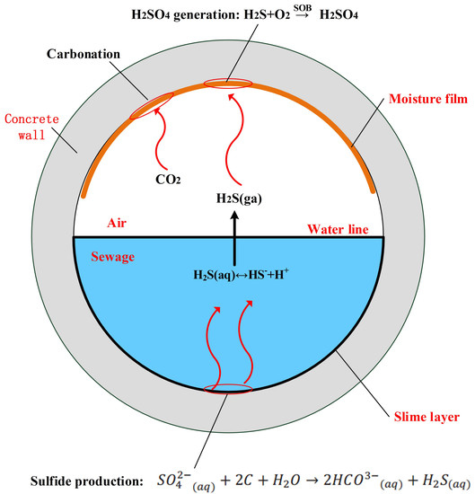
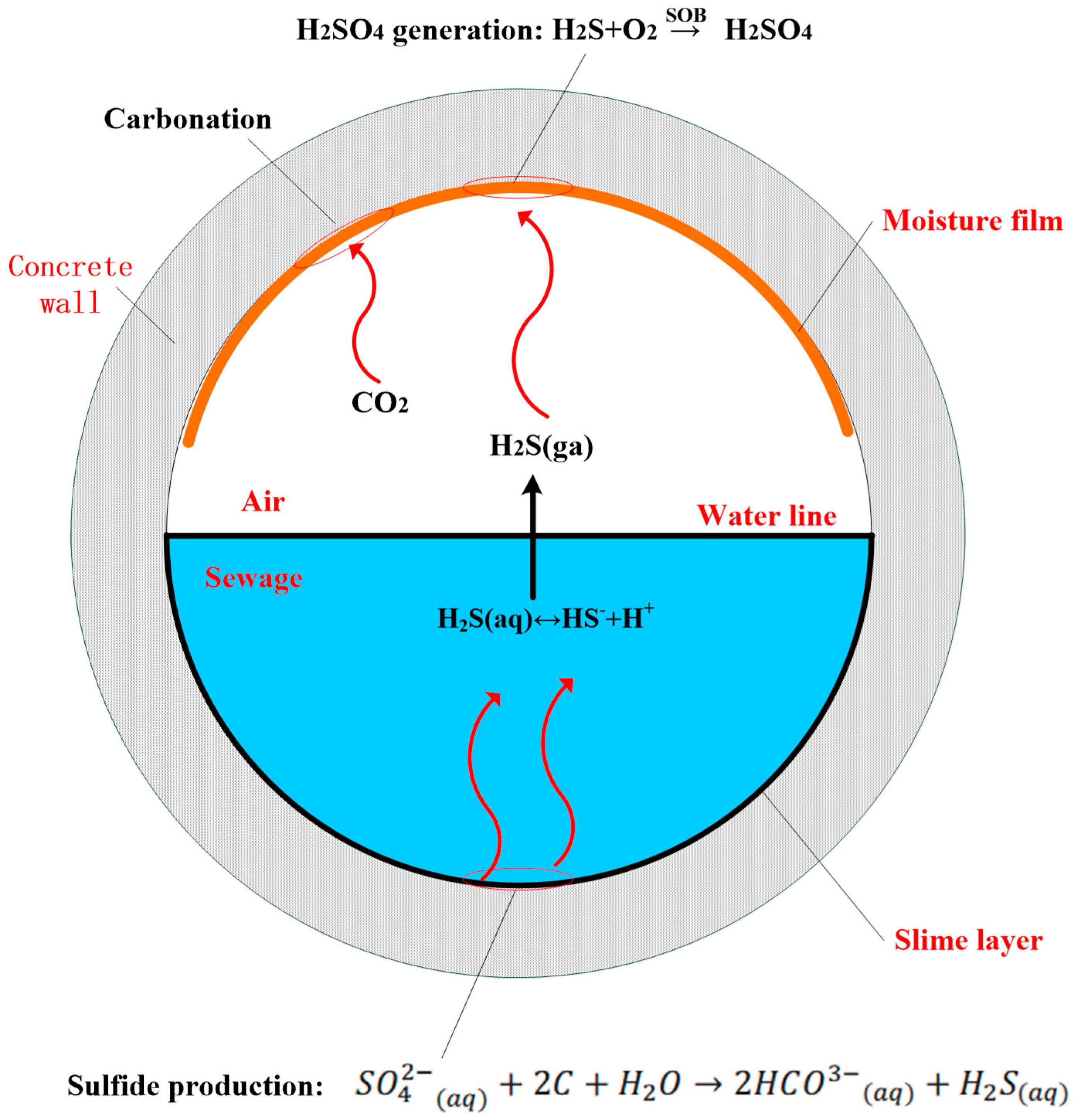
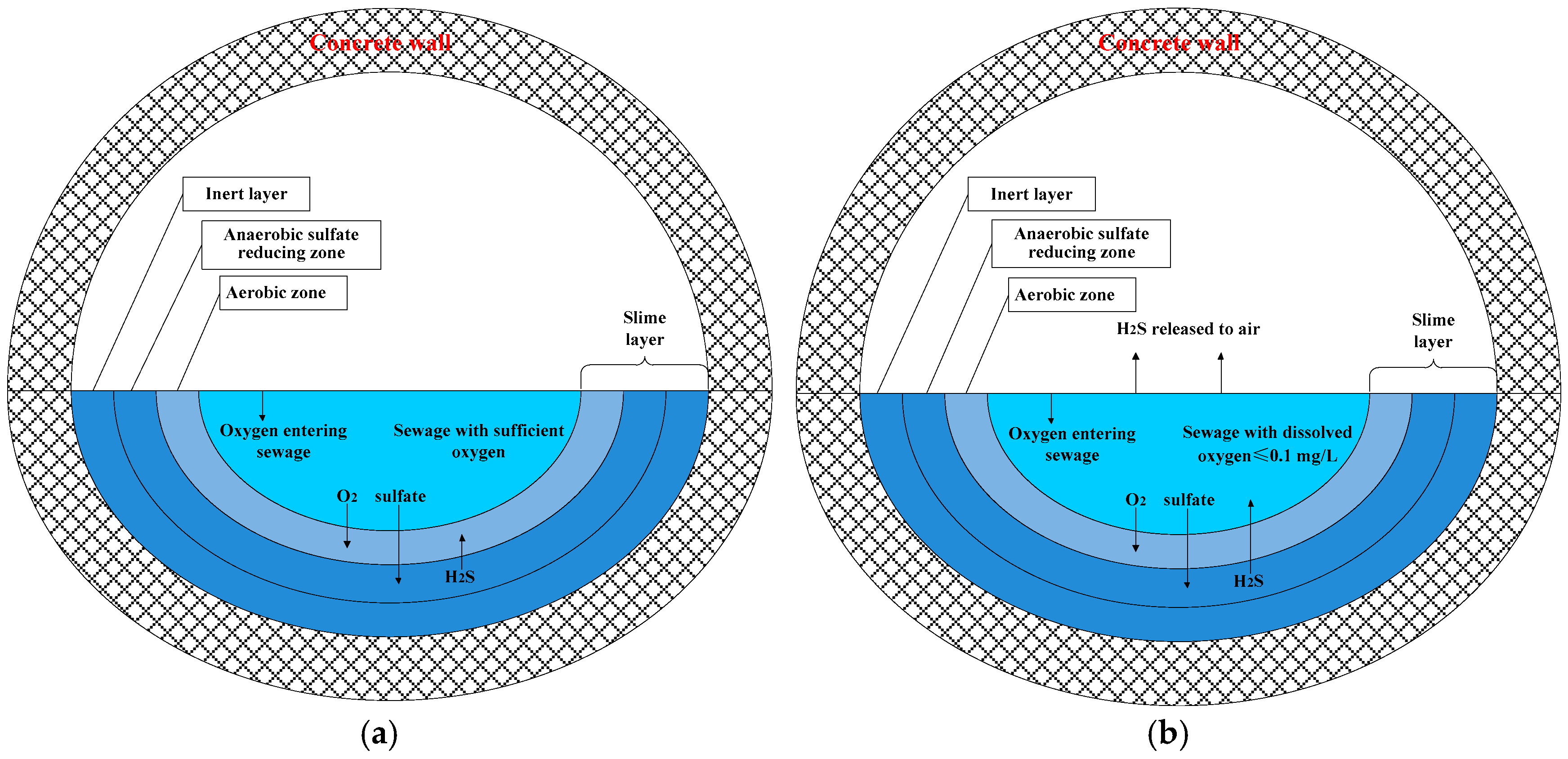
2.1. Hydrogen Sulfide Generation
2.2. H2S Release from Sewage and Subsequent Sulfide Buildup at Crown
2.3. Carbonation of Concrete Surface
2.4. Sulfide Oxidation
2.5. Acid Corrosion Reaction
3. Discussions about Potential Methods to Control Microbially Induced Corrosion
3.1. Changing Sewer Tunnel Environment
3.2. Using Proper Hydraulic Parameters in Sewer Design
- When debris and sediment buildup cause long retention or low flow velocity, a good maintenance plan is more efficient than proper tunnel design to minimize the buildup of hydrogen sulfide.
- When the long retention is caused by the storage of wastewater—at locations such as pump stations—chemical dosing to the wastewater in a wet well will greatly reduce the chance of H2S generation [47].
- When sudden turbulence is inevitable, the quality of wastewater upstream of the turbulence should be carefully evaluated before selecting the pipe material.
3.3. Improving Concrete Mixture Design
3.4. Other Methods
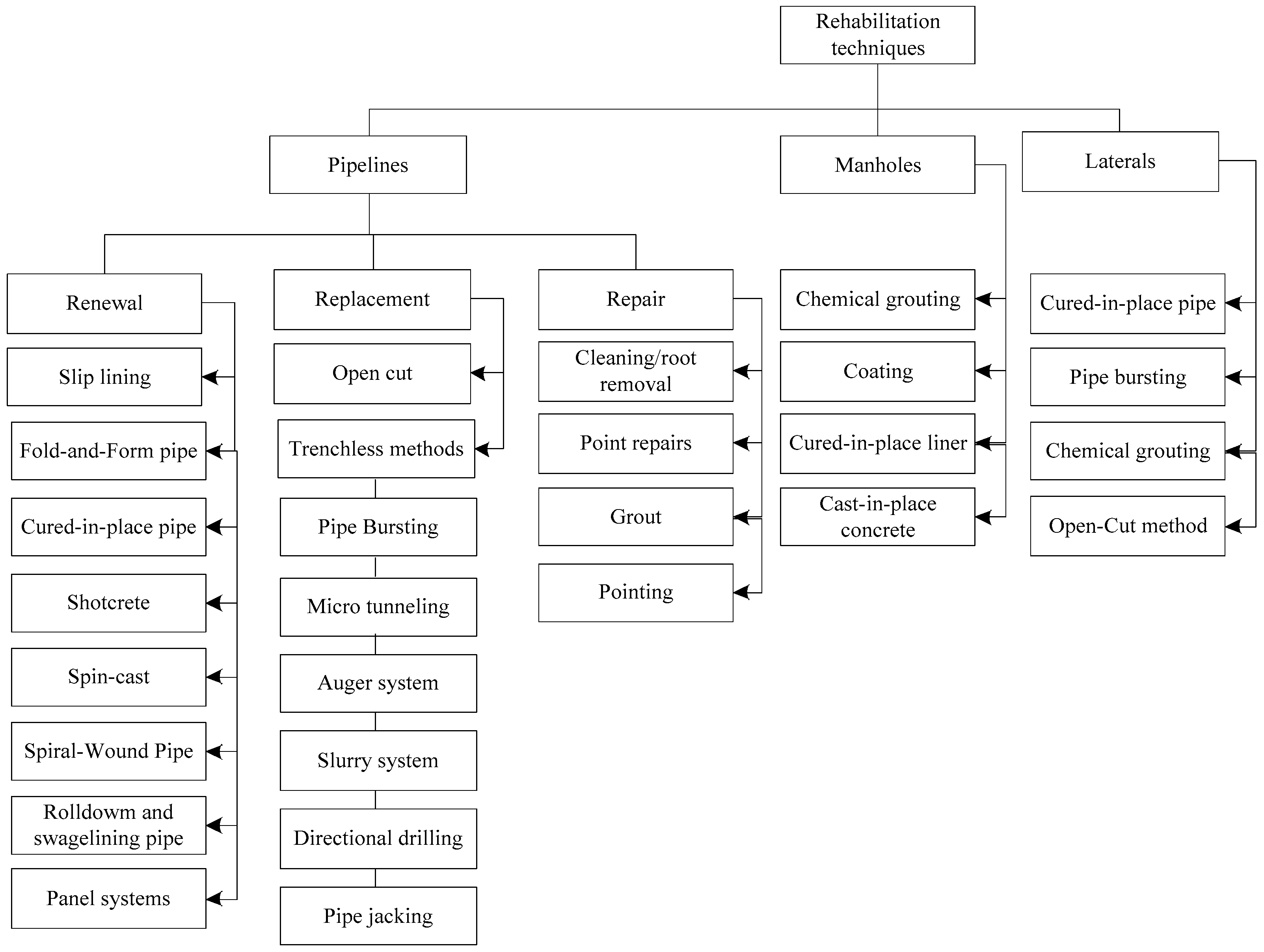
4. Rehabilitation
4.1. Cement-Based Rehabilitation Techniques
4.1.1. Shotcrete
4.1.2. Cast-in-Place Method
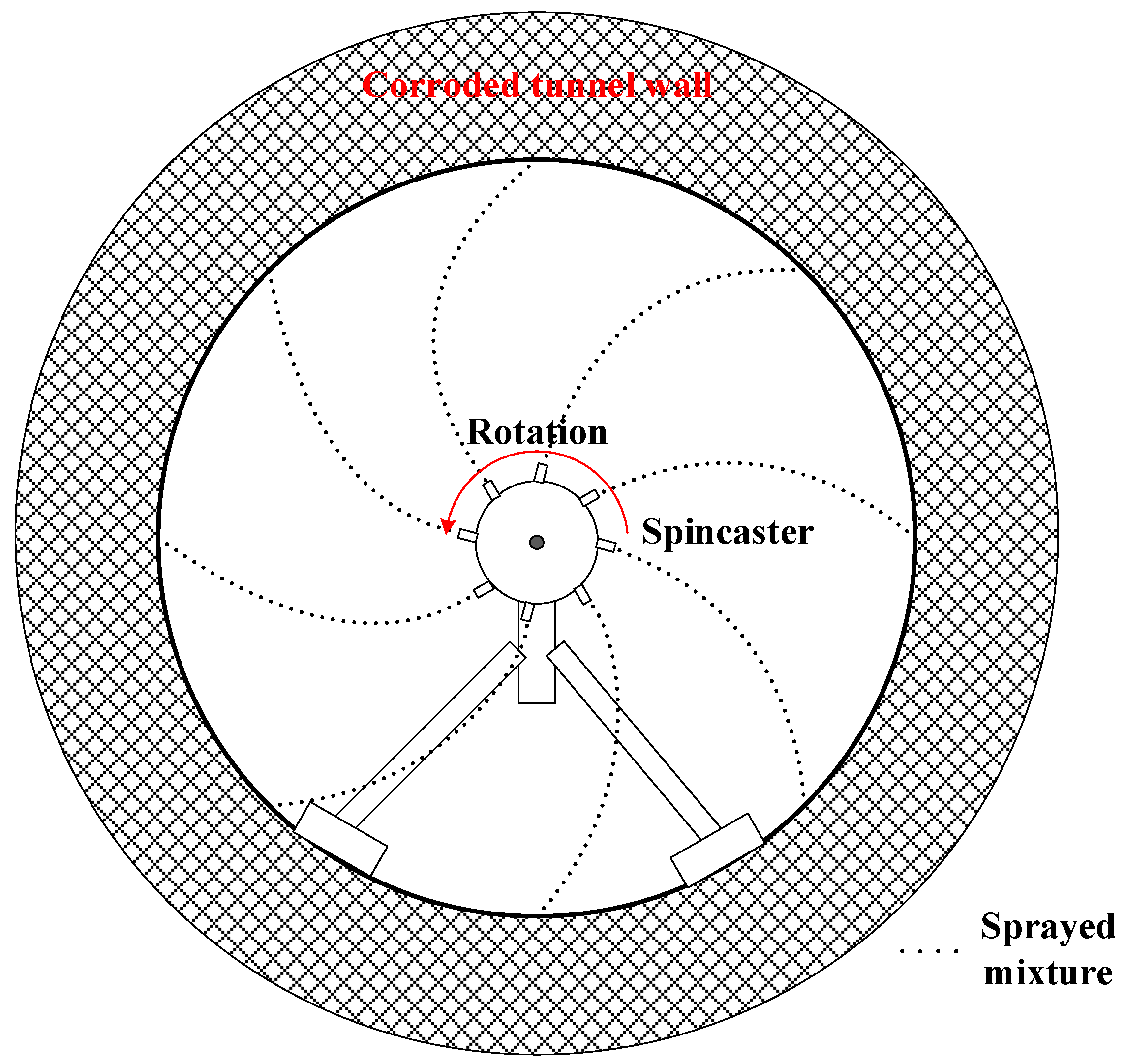
4.1.3. Spin-Cast Method
4.2. Cement-Based Rehabilitation—Method Selection
4.3. Cement-Based Rehabilitation—Material Selection Based on the Acid Resistance
5. Drainage Design Standards
5.1. Flow Velocity
5.2. Retention Time
5.3. Mixture Design in the Concrete Liner
6. Concluding Remarks
- Three categories of main influencing factors were identified for the rate of MIC: hydraulic parameters, environmental factors, and concrete mixture design.
- Many chemicals dosed to the sewage have been effective in reducing sulfide concentrations in sewage such as magnesium hydroxide, sodium hydroxide, iron salts, free nitrous acid (FNA), nitrate, oxygen, hydrogen peroxide, ozone, chlorine, and permanganate.
- A proper sewer tunnel design is an efficient and cost-efficient method to control MIC. It is recommended to consider MIC during the hydraulic design phase. However, the current COE standards do not include any related regulations.
- All hydraulic-cement concretes, regardless of the composition, are unable to withstand for long in an acid with a pH below 3. However, improving the concrete mixture design is still a viable method for controlling MIC rate because it changes the rate of the corrosion reaction process.
- Cement-based rehabilitation methods can be used in severely deteriorated tunnels to provide structural restoration. However, supplementary measures (e.g., coating and chemical dosing) should be taken to prevent future corrosion, due to the alkaline nature of the cement-based material.
- No available testing standard was found that guides the acid resistance test of cement-based material at present.
- There is a lack of regulations on commonly used non-cement materials in COE standards. It is recommended to include a list of approved materials in the COE standards specifying the characteristics of the materials such as the bonding strength with a substrate, acid corrosion resistance, correspondent rehabilitation techniques, and costs.
Acknowledgments
Author Contributions
Conflicts of Interest
References
- U.S. Environmental Protection Agency. Hydrogen Sulfide Corrosion in Wastewater Collection and Treatment Systems; U.S. Environmental Protection Agency: Washington, DC, USA, 1991; p. 59.
- Apgar, D.; Witherspoon, J. Minimization of Odors and Corrosion in Collection Systems; Water Environment Research Foundation: Alexandria, VA, USA, 2008. [Google Scholar]
- Brongers, M.; Virmani, P.; Payer, J. Drinking Water and Sewer Systems in Corrosion Costs and Preventative Strategies in the United States; United States Department of Transportation Federal Highway Administration: Washington, DC, USA, 2002. [Google Scholar]
- Neville, A. Chloride attack of reinforced concrete: An overview. Mater. Struct. 1995, 28, 63–70. [Google Scholar] [CrossRef]
- Emmanuel, K.A.; Sami, H.R. Response of concrete to sulfuric acid attack. Mater. J. 1988, 85, 481–488. [Google Scholar]
- Stolte, E. Major Edmonton Sewer Trunk Line Hanging on by “Ribs and Lagging”. Available online: http://edmontonjournal.com/news/local-news/major-edmonton-sewer-trunk-line-hanging-on-by-ribs-and-lagging (accessed on 31 August 2017).
- Chris Ward. City of Edmonton. In 2016–2018 Business Plan; Utility Services: City of Edmonton, AB, Canada, 2016; p. 19. Available online: https://www.edmonton.ca/city_government/documents/Utility_Services_Business_Plan_2016-2018.pdf (accessed on 31 August 2017).
- Jiang, G.; Keller, J.; Bond, P.L.; Yuan, Z. Predicting concrete corrosion of sewers using artificial neural network. Water Res. 2016, 92, 52–60. [Google Scholar] [CrossRef] [PubMed]
- Alexander, M.; Fourie, C. Performance of sewer pipe concrete mixtures with portland and calcium aluminate cements subject to mineral and biogenic acid attack. Mater. Struct. 2011, 44, 313–330. [Google Scholar] [CrossRef]
- House, M.W. Using Biological and Physico-Chemical Test Methods to Assess the Role of Concrete Mixture Design in Resistance to Microbially Induced Corrosion; Purdue University: West Lafayette, IN, USA, 2013. [Google Scholar]
- Reardon, E.J. An ion interaction model for the determination of chemical equilibria in cement/water systems. Cem. Concr. Res. 1990, 20, 175–192. [Google Scholar] [CrossRef]
- Wells, T.; Melchers, R.E. An observation-based model for corrosion of concrete sewers under aggressive conditions. Cem. Concr. Res. 2014, 61–62, 1–10. [Google Scholar] [CrossRef]
- Æsøy, A.; Østerhus, S.W.; Bentzen, G. Controlled treatment with nitrate in sewers to prevent concrete corrosion. Water Sci. Technol. 2002, 2, 137–144. [Google Scholar]
- Okun, D.A.; Wang, L.K.; Shammas, N.K. Water Supply and Distribution and Wastewater Collection; John Wiley and Sons: Hoboken, NJ, USA, 2010. [Google Scholar]
- Bowker, R.P.; Smith, J.M. Odor and Corrosion Control in Sanitary Sewerage Systems and Treatment Plants; U.S. Environmental Protection Agency: Washington, DC, USA, 1985. [Google Scholar]
- Hewayde, E.H. Investigation on Degradation of Concrete Sewer Pipes by Sulfuric Acid Attack. Ph.D. Thesis, The University of Western Ontario, London, ON, Canada, 2005. [Google Scholar]
- Firer, D.; Friedler, E.; Lahav, O. Control of sulfide in sewer systems by dosage of iron salts: Comparison between theoretical and experimental results, and practical implications. Sci. Total Environ. 2008, 392, 145–156. [Google Scholar] [CrossRef] [PubMed]
- House, M.W.; Weiss, W.J. Review of microbially induced corrosion and comments on needs related to testing procedures. In Proceedings of the 4th International Conference on the Durability of Concrete Structures, ICDCS 2014, West Lafayette, IN, USA, 24–26 July 2014; Purdue University: West Lafayette, IN, USA, 2014; pp. 94–103. [Google Scholar]
- Wells, T.; Melchers, R.E.; Bond, P. Factors involved in the long term corrosion of concrete sewers. In Proceedings of the Australasian Corrosion Association Proceedings of Corrosion and Prevention, Coffs Harbour, Australia, 15–18 November 2009. [Google Scholar]
- Vollertsen, J.; Nielsen, A.H.; Jensen, H.S.; Wium-Andersen, T.; Hvitved-Jacobsen, T. Corrosion of concrete sewers—The kinetics of hydrogen sulfide oxidation. Sci. Total Environ. 2008, 394, 162–170. [Google Scholar] [CrossRef] [PubMed]
- Sun, X. Improving the Understanding of Concrete Sewer Corrosion through Investigations of the Gaseous Hydrogen Sulfide Uptake and Transformation Processes in the Corrosion Laye; The University of Queensland: Brisbane, Queensland, 2015. [Google Scholar]
- American Concrete Institute (ACI) Committee 201. Guide to Durable Concrete; ACI Committee: Farmington Hills, MI, USA, 2001. [Google Scholar]
- Portland Cement Association. Concrete Information: Types and Causes of Concrete Deterioration; PCA R&D Serial; Portland Cement Association: Skokie, IL, USA, 2002; Available online: http://www.cement.org/docs/default-source/fc_concrete_technology/durability/is536-types-and-causes-of-concrete-deterioration.pdf?sfvrsn=4 (accessed on 15 July 2017).
- Huseyin, S.; Mohammed, M.; Mohammed, S.; Ibrabimm, A. Case study of deterioration of concrete in sewage environment in an Arabian Gulf country. Durab. Build. Mater. 1987, 5, 145–154. [Google Scholar]
- Joseph, A.P.; Keller, J.; Bustamante, H.; Bond, P.L. Surface neutralization and h2s oxidation at early stages of sewer corrosion: Influence of temperature, relative humidity and h2s concentration. Water Res. 2012, 46, 4235–4245. [Google Scholar] [CrossRef] [PubMed]
- Sublette, K.L.; Kolhatkar, R.; Raterman, K. Technological aspects of the microbial treatment of sulfide-rich wastewaters: A case study. Biodegradation 1998, 9, 259–271. [Google Scholar] [CrossRef] [PubMed]
- Rootsey, R.; Melchers, R.; Stuetz, R.; Keller, J.; Yuan, Z. Taking control of odours and corrosion in sewers. In Proceedings of the Australia’s National Water Conference and Exhibition (OzWater 2012), Sydney, Australia, 8–10 May 2012; pp. 8–10. [Google Scholar]
- Islander, R.L.; Devinny, J.S.; Mansfeld, F.; Postyn, A.; Shih, H. Microbial ecology of crown corrosion in sewers. J. Environ. Eng. 1991, 117, 751–770. [Google Scholar] [CrossRef]
- Wells, T.; Melchers, R.; Joseph, A.; Bond, P.; Vitanage, D.; Bustamante, H.; De Grazia, J.; Kuen, T.; Nazimek, J.; Evans, T. A Collaborative Investigation of the Microbial Corrosion of Concrete Sewer Pipe in Australia; Australian Water Association: St Leonards, Australia, 2012. [Google Scholar]
- Idriss, A.; Negi, S.; Jofriet, J.; Hayward, G. Effect of hydrogen sulphide emissions on cement mortar specimens. Can. Biosyst. Eng. 2001, 43, 523–528. [Google Scholar]
- Parande, A.; Ramsamy, P.; Ethirajan, S.; Rao, C.; Palanisamy, N. Deterioration of reinforced concrete in sewer environments. Proc. Inst. Civ. Eng.-Munic. Eng. 2006, 159, 11–20. [Google Scholar] [CrossRef]
- Jiang, G.; Wightman, E.; Donose, B.C.; Yuan, Z.; Bond, P.L.; Keller, J. The role of iron in sulfide induced corrosion of sewer concrete. Water Res. 2014, 49, 166–174. [Google Scholar] [CrossRef] [PubMed]
- Hewayde, E.; Nehdi, M.; Allouche, E.; Nakhla, G. Effect of mixture design parameters and wetting-drying cycles on resistance of concrete to sulfuric acid attack. J. Mater. Civ. Eng. 2007, 19, 155–163. [Google Scholar] [CrossRef]
- Ganigue, R.; Gutierrez, O.; Rootsey, R.; Yuan, Z. Chemical dosing for sulfide control in Australia: An industry survey. Water Res. 2011, 45, 6564–6574. [Google Scholar] [CrossRef] [PubMed]
- Sun, J.; Pikaar, I.; Sharma, K.R.; Keller, J.; Yuan, Z. Feasibility of sulfide control in sewers by reuse of iron rich drinking water treatment sludge. Water Res. 2015, 71, 150–159. [Google Scholar] [CrossRef] [PubMed]
- Zhang, L.; Keller, J.; Yuan, Z. Inhibition of sulfate-reducing and methanogenic activities of anaerobic sewer biofilms by ferric iron dosing. Water Res. 2009, 43, 4123–4132. [Google Scholar] [CrossRef] [PubMed]
- Jiang, G.; Gutierrez, O.; Yuan, Z. The strong biocidal effect of free nitrous acid on anaerobic sewer biofilms. Water Res. 2011, 45, 3735–3743. [Google Scholar] [CrossRef] [PubMed]
- Jiang, G.; Gutierrez, O.; Sharma, K.R.; Keller, J.; Yuan, Z. Optimization of intermittent, simultaneous dosage of nitrite and hydrochloric acid to control sulfide and methane productions in sewers. Water Res. 2011, 45, 6163–6172. [Google Scholar] [CrossRef] [PubMed]
- Mohanakrishnan, J.; Gutierrez, O.; Meyer, R.L.; Yuan, Z. Nitrite effectively inhibits sulfide and methane production in a laboratory scale sewer reactor. Water Res. 2008, 42, 3961–3971. [Google Scholar] [CrossRef] [PubMed]
- Mohanakrishnan, J.; Gutierrez, O.; Sharma, K.R.; Guisasola, A.; Werner, U.; Meyer, R.L.; Keller, J.; Yuan, Z. Impact of nitrate addition on biofilm properties and activities in rising main sewers. Water Res. 2009, 43, 4225–4237. [Google Scholar] [CrossRef] [PubMed]
- Gutierrez, O.; Mohanakrishnan, J.; Sharma, K.R.; Meyer, R.L.; Keller, J.; Yuan, Z. Evaluation of oxygen injection as a means of controlling sulfide production in a sewer system. Water Res. 2008, 42, 4549–4561. [Google Scholar] [CrossRef] [PubMed]
- Cadena, F.; Peters, R.W. Evaluation of chemical oxidizers for hydrogen sulfide control. Water Pollut. Control Fed. 1988, 60, 1259–1263. [Google Scholar]
- Subcommittee on Paints and Protective Coatings. Paints and Protective Coatings for Wastewater Treatment Facilities; Volume Manual of Practice No. 17; Water Pollution Control Federation: Washington, DC, USA, 1969. [Google Scholar]
- Pomeroy, R.; Bowlus, F.D. Progress report on sulfide control research. Sew. Works J. 1946, 18, 597–640. [Google Scholar]
- USP Technoligies. Force Main System Sulfide Control with Hydrogen Peroxide. Available online: http://www.h2o2.com/municipal-applications/wastewater-treatment.aspx?pid=128& (accessed on 29 May 2017).
- Churchill, P.; Elmer, D. Hydrogen sulfide odor control in wastewater collection systems. J. N. Engl. Water Environ. Assoc. 1999, 33, 57–63. [Google Scholar]
- Clidence, D.; Shissler, D. Elimination of odor and hydrogen sulfide gas by superoxygenation of the bluebird force main in Laguna beach, California. Proc. Water Environ. Fed. 2008, 2008, 815–825. [Google Scholar] [CrossRef]
- Hossain, M.M.; Karim, M.R.; Hasan, M.; Hossain, M.K.; Zain, M.F.M. Durability of mortar and concrete made up of pozzolans as a partial replacement of cement: A review. Constr. Build. Mater. 2016, 116, 128–140. [Google Scholar] [CrossRef]
- Sabir, B.B.; Wild, S.; Bai, J. Metakaolin and calcined clays as pozzolans for concrete: A review. Cem. Concr. Compos. 2001, 23, 441–454. [Google Scholar] [CrossRef]
- Mehta, P.K. Properties of blended cements made from rice husk ash. J. Am. Concr. Inst. 1977, 74, 440–442. [Google Scholar]
- Torii, K.; Kawamura, M. Effects of fly ash and silica fume on the resistance of mortar to sulfuric acid and sulfate attack. Cem. Concr. Res. 1994, 24, 361–370. [Google Scholar] [CrossRef]
- Roy, D.M.; Arjunan, P.; Silsbee, M.R. Effect of silica fume, metakaolin, and low-calcium fly ash on chemical resistance of concrete. Cem. Concr. Res. 2001, 31, 1809–1813. [Google Scholar] [CrossRef]
- Duan, P.; Shui, Z.; Chen, W.; Shen, C. Effects of metakaolin, silica fume and slag on pore structure, interfacial transition zone and compressive strength of concrete. Constr. Build. Mater. 2013, 44, 1–6. [Google Scholar] [CrossRef]
- Dunster, A.M.; Parsonage, J.R.; Thomas, M.J.K. The pozzolanic reaction of metakaolinite and its effects on portland cement hydration. J. Mater. Sci. 1993, 28, 1345–1350. [Google Scholar] [CrossRef]
- Gruyaert, E.; Van den Heede, P.; Maes, M.; De Belie, N. Investigation of the influence of blast-furnace slag on the resistance of concrete against organic acid or sulphate attack by means of accelerated degradation tests. Cem. Concr. Res. 2012, 42, 173–185. [Google Scholar] [CrossRef]
- Monteny, J.; De Belie, N.; Taerwe, L. Resistance of different types of concrete mixtures to sulfuric acid. Mater. Struct. 2003, 36, 242–249. [Google Scholar] [CrossRef]
- Chatveera, B.; Lertwattanaruk, P.; Makul, N. Effect of sludge water from ready-mixed concrete plant on properties and durability of concrete. Cem. Concr. Compos. 2006, 28, 441–450. [Google Scholar] [CrossRef]
- Senhadji, Y.; Escadeillas, G.; Mouli, M.; Khelafi, H.; Benosman. Influence of natural pozzolan, silica fume and limestone fine on strength, acid resistance and microstructure of mortar. Powder Technol. 2014, 254, 314–323. [Google Scholar] [CrossRef]
- Kannan, V.; Ganesan, K. Chloride and chemical resistance of self compacting concrete containing rice husk ash and metakaolin. Constr. Build. Mater. 2014, 51, 225–234. [Google Scholar] [CrossRef]
- Tamimi, A. High-performance concrete mix for an optimum protection in acidic conditions. Mater. Struct. 1997, 30, 188–191. [Google Scholar] [CrossRef]
- Hewayde, E.; Nehdi, M.L.; Allouche, E.; Nakhla, G. Using concrete admixtures for sulphuric acid resistance. Proc. Inst. Civ. Eng. Constr. Mater. 2007, 160, 25–35. [Google Scholar] [CrossRef]
- Conshield Inc. Technical Bulletin-Conshield. Available online: http://www.conshield.com/ConShield/TheScienceofConShield/tabid/89/Default.aspx (accessed on 25 July 2017).
- Park, S.-K.; Kim, J.-H.J.; Nam, J.-W.; Phan, H.D.; Kim, J.-K. Development of anti-fungal mortar and concrete using zeolite and zeocarbon microcapsules. Cem. Concr. Compos. 2009, 31, 447–453. [Google Scholar] [CrossRef]
- Freed, W.W. Reinforced Concrete Containing Antimicrobial-Enhanced Fibers. Google Patents WO 1995006086 A3, 2000. [Google Scholar]
- Emmel, T.; Brill, H.; Sand, W.; Bock, E. Screening for biocides to inhibit biogenic sulphuric acid corrosion in sewage pipelines. In Biodeterioration 7; Houghton, D.R., Smith, R.N., Eggins, H.O.W., Eds.; Springer: Dordrecht, The Netherlands, 1988; pp. 118–122. [Google Scholar]
- Valix, M.; Zamri, D.; Mineyama, H.; Cheung, W.H.; Shi, J.; Bustamante, H. Microbiologically induced corrosion of concrete and protective coatings in gravity sewers. Chin. J. Chem. Eng. 2012, 20, 433–438. [Google Scholar] [CrossRef]
- Sun, X.; Jiang, G.; Chiu, T.H.; Zhou, M.; Keller, J.; Bond, P.L. Effects of surface washing on the mitigation of concrete corrosion under sewer conditions. Cem. Concr. Compos. 2016, 68, 88–95. [Google Scholar] [CrossRef]
- Water Environment Federation. Existing Sewer Evaluation and Rehabilitation, WEF Manual of Practice 3rd ed.; WEF Press—Water Environment Federation: Alexandria, VA, USA, 2009. [Google Scholar]
- Morrison, R.; Sangster, T.; Downey, D.; Matthews, J.; Condit, W.; Sinha, S.; Maniar, S.; Sterling, R. State of Technology for Rehabilitation of Water Distribution Systems; EPA/600/R-13/036 2013; United States Environmental Protection Agency: Washington, DC, USA, 2013.
- American Concrete Institute (ACI) Committee 506. Guide to Shotcrete; ACI Committee: Farmington Hills, MI, USA, 2016; Available online: https://www.concrete.org/store/productdetail.aspx?ItemID=50616&Language=English (accessed on 17 June 2017).
- Schrader, E.K.; Kaden, R.A. Durability of shotcrete. Spec. Publ. 1987, 100, 1071–1102. Available online: https://www.concrete.org/publications/internationalconcreteabstractsportal/m/details/id/3744 (accessed on 21 June 2017).
- McAlpine, G.; Anderson, B. Structural rehabilitation of cast-in-place concrete sewers. In Pipelines 2005: Optimizing Pipeline Design, Operations, and Maintenance in Today’s Economy; American Society of Civil Engineers (ASCE): Reston, VA, USA, 2005; pp. 510–522. Available online: https://ascelibrary.org/doi/pdf/10.1061/40800%28180%2940 (accessed on 7 February 2018).
- Stein, D.; Stein, R. Rehabilitation and Maintenance of Drains and Sewers (e-book). UNITRACC.com. 2004. Available online: https://www.unitracc.com/know-how/fachbuecher/rehabilitation-and-maintenance-of-drains-and-sewers (accessed on 7 February 2018).
- Norman, E. Manhole rehabilitation: Delivering on the design with proper installation practices and related quality assurance testing. In Proceedings of the North American Society for Trenchless Technology (NASTT) NASTT’s 2016 No-Dig Show, Dallas, TX, USA, 20–24 March 2016; p. 9. [Google Scholar]
- Koehn, K.W. Methods and Benefits of Spincasting Cements on Corrugated Metal Pipes; C. K. Masonry Co. Inc.: Nashville, TN, USA, 1994; p. 4. [Google Scholar]
- Dinakar, P.; Babu, K.G.; Santhanam, M. Durability properties of high volume fly ash self compacting concretes. Cem. Concr. Compos. 2008, 30, 880–886. [Google Scholar] [CrossRef]
- Pavel, R.; Jiří, T. Resistance of concrete with metakaolin addition to acid environment. Key Eng. Mater. 2016, 677, 144–149. [Google Scholar]
- Durning, T.A.; Hicks, M.C. Using microsilica to increase concrete’s resistance to aggressive chemicals. Concr. Int. 1991, 13, 42–48. [Google Scholar]
- Ekolu, S.O.; Diop, S.; Azene, F.; Mkhize, N. Disintegration of concrete construction induced by acid mine drainage attack. J. S. Afr. Inst. Civ. Eng. 2016, 58, 34–42. [Google Scholar] [CrossRef]
- Shetti, A.P.; Das, B.B. Acid, alkali and chloride resistance of early age cured silica fume concrete. In Advances in Structural Engineering: Materials; Springer: New Delhi, India, 2015; Volume 3, pp. 1849–1862. [Google Scholar]
- Chindaprasirt, P.; Homwuttiwong, S.; Sirivivatnanon, V. Influence of fly ash fineness on strength, drying shrinkage and sulfate resistance of blended cement mortar. Cem. Concr. Res. 2004, 34, 1087–1092. [Google Scholar] [CrossRef]
- Newman, J.; Choo, B.S. Advanced Concrete Technology 3: Processes; Butterworth-Heinemann: Oxford, UK, 2003. [Google Scholar]
- Mori, T.; Nonaka, T.; Tazaki, K.; Koga, M.; Hikosaka, Y.; Noda, S. Interactions of nutrients, moisture and pH on microbial corrosion of concrete sewer pipes. Water Res. 1992, 26, 29–37. [Google Scholar] [CrossRef]
- Sand, W. Biotest system for rapid evaluation of concrete resitance to sulfur-oxidizing bacteria. Mater. Perform. 1987, 26, 14–17. [Google Scholar]
- Shing, C.K.; Wu, C.L.; Chen, J.W.; Yuen, C.S.; Tsui, R.Y. A review on protection of concrete for sewage installations and an accelerated test on protection systems. HKIE Trans. 2012, 19, 8–16. [Google Scholar]
- Koenig, A.; Dehn, F. Main considerations for the determination and evaluation of the acid resistance of cementitious materials. Mater. Struct. 2016, 49, 1693–1703. [Google Scholar] [CrossRef]
- Breit, W. Säurewiderstand von beton-acid resistance of concrete. Beton 2002, 52, 505–510. [Google Scholar]
- Fernando, P.-T.; Said, J. Resistance to acid attack, abrasion and leaching behavior of alkali-activated mine waste binders. Mater. Struct. 2011, 44, 487–498. [Google Scholar] [CrossRef] [Green Version]
- Aydın, S.; Yazıcı, H.; Yiğiter, H.; Baradan, B. Sulfuric acid resistance of high-volume fly ash concrete. Build. Environ. 2007, 42, 717–721. [Google Scholar] [CrossRef]
- Ariffin, M.; Bhutta, M.; Hussin, M.; Tahir, M.M.; Aziah, N. Sulfuric acid resistance of blended ash geopolymer concrete. Constr. Build. Mater. 2013, 43, 80–86. [Google Scholar] [CrossRef]
- Jerlin Regin, J.; Vincent, P.; Ganapathy, C. Effect of mineral admixtures on mechanical properties and chemical resistance of lightweight coconut shell concrete. Arab. J. Sci. Eng. 2017, 42, 957–971. [Google Scholar] [CrossRef]
- Chang, Z.T.; Song, X.J.; Munn, R.; Marosszeky, M. Using limestone aggregates and different cements for enhancing resistance of concrete to sulphuric acid attack. Cem. Concr. Res. 2005, 35, 1486–1494. [Google Scholar] [CrossRef]
- De Belie, N.; Monteny, J.; Taerwe, L. Apparatus for accelerated degradation testing of concrete specimens. Mater. Struct. 2002, 35, 427–433. [Google Scholar] [CrossRef]
- Macías, A.; Goni, S.; Madrid, J. Limitations of köch-steinegger test to evaluate the durability of cement pastes in acid medium. Cem. Concr. Res. 1999, 29, 2005–2009. [Google Scholar] [CrossRef]
- Yuan, H.; Dangla, P.; Chatellier, P.; Chaussadent, T. Degradation modelling of concrete submitted to sulfuric acid attack. Cem. Concr. Res. 2013, 53, 267–277. [Google Scholar] [CrossRef]
- Ondrejka Harbulakova, V.; Estokova, A.; Kovalcikova, M. Correlation analysis between different types of corrosion of concrete containing sulfate resisting cement. Environments 2017, 4, 44. [Google Scholar] [CrossRef]
- Alexander, M.; Bertron, A.; De Belie, N. Performance of Cement-Based Materials in Aggressive Aqueous Environments; Springer: New York, NY, USA, 2013; Volume 10. [Google Scholar]
- Government of the Hong Kong-Special Administrative Region. Sewerage manual. In Key Planning Issues and Gravity Collection System; Drainage Services Department: Hong Kong, China, 2013. [Google Scholar]
- City of Edmonton. In Design and Construction Standards; Volume 3-Drainage; Edmonton, AB, Canada, 2015; Available online: https://www.edmonton.ca/city_government/documents/Volume_3_Drainage_.pdf (accessed on 12 June 2017).
- City of London (Canada). In Design Specifications & Requirements Manual; City of London, 2015; Available online: http://www.london.ca/business/Resources/Consultant-Resources/Documents/Specs%20and%20Reqs%202015/DSRM-2015-EntireDoc.pdf (accessed on 12 June 2017).
- City of Toronto. In Design Criteria for Sewers and Watermains. Standards, Policies and Quality Assurance, District Engineering Services; 2009; Available online: https://www.toronto.ca/wp-content/uploads/2017/11/9753-ecs-specs-dcm-Toronto_Sewer_and_Watermain_Manual_March2014.pdf (accessed on 12 June 2017).
- City of Saskatoon. In Design and Development Standards Manual in Section Five-Sanitary Sewer Collection System, City of Saskatoon; 2017; Available online: https://www.saskatoon.ca/sites/default/files/documents/transportation-utilities/construction-design/new-neighbourhood-design/5._2017_section_five_-_sanitary_sewer_collection_system.pdf (accessed on 12 June 2017).
- City of Kamloops. In Design Criteria Manual; Development and Engineering Services Department-Engineering Development Section: Kamloops, BC, Canada, 2012; Available online: https://www.kamloops.ca/sites/default/files/docs/city-services/12-designcriteriamanual.pdf (accessed on 12 June 2017).
- City of Dallas. In Water and Wastewater Procedures and Design Manual; Dallas Water Utilities, 2015; Available online: http://dallascityhall.com/departments/waterutilities/DCH%20Documents/pdf/Water_and_Wastewater_Procedures_and_Design_Manual_October_2015.pdf (accessed on 12 June 2017).
- Singapore. In Code of Practice in Sewerage and Sanitary Works Water, Reclamation (Network) Department; 2004; Available online: https://www.scribd.com/document/39703354/Code-of-Practice-on-Sewerage-and-Sanitary-Works (accessed on 12 June 2017).
- Larsen, T.A.; Udert, K.M.; Lienert, J. Source Separation and Decentralization for Wastewater Management. Iwa Publishing: London, UK, 2013. [Google Scholar]
- Klassen, A. Sewer-System Fix Is Costly. Available online: http://www.kamloopsthisweek.com/sewer-system-fix-is-costly/ (accessed on 21 June 2017).
- Wodetzki, B.; Kaakaty, C. Iron-the optimal solution for odor and corrosion. Proc. Water Environ. Fed. 2013, 2013, 5467–5472. [Google Scholar] [CrossRef]
- Jenkins, S.H. Eighth International Conference on Water Pollution Research: Proceedings of the 8th International Conference, Sydney, Australia, 1976; Elsevier: Amsterdam, The Netherlands, 2013. [Google Scholar]
- Canadian Standards Association (CSA). A23.1-14/a23.2-14—Concrete Materials and Methods of Concrete Construction/Test Methods and Standard Practices for Concrete; CSA: Mississauga, ON, Canada, 2014. [Google Scholar]
- Canadian Standards Association (CSA). A257.2-14—Reinforced Circular Concrete Culvert, Storm Drain, Sewer Pipe, and Fittings; CSA: Mississauga, ON, Canada, 2014. [Google Scholar]
- Canadian Standards Association (CSA). A257.1-14—Non-Reinforced Circular Concrete Culvert, Storm Drain, Sewer Pipe, and Fittings; CSA: Mississauga, ON, Canada, 2014. [Google Scholar]
- Canadian Standards Association (CSA). A23.4-16—Precast Concrete—Materials and Construction; CSA: Mississauga, ON, Canada, 2000. [Google Scholar]
- American Society for Testing Materials (ASTM). Astm c404—11 Standard Specification for Aggregates for Masonry Grout; ASTM International: West Conshohocken, PA, USA, 2011. [Google Scholar]
- Canadian Standards Association (CSA). A3000-13—Cementitious Materials Compendium; CSA: Mississauga, ON, Canada, 2013. [Google Scholar]


| Factors | Effects on H2S Generation |
|---|---|
| DO |
|
| BOD |
|
| Wastewater temperature |
|
| Flow velocity |
|
| Retention time |
|
| Factors | Effects |
|---|---|
| Wastewater pH | Wastewater pH affects the H2S(aq) concentration in sewage |
| Wastewater temperature | Low temperature reduces the H2S solubility in sewage |
| Turbulence | Strong turbulence exacerbates the H2S release by increasing the area of sewage-air interface |
| Factors | Effects |
|---|---|
| RH | The highest rates of carbonation occur in environments in which the RH of the surrounding atmosphere is kept in the range of 50% to 75% [22]. |
| Permeability | Low permeability inhibits the penetration of CO2, restricting the carbonation to the concrete surface. |
| Factors | Effects |
|---|---|
| RH | High RH increases the rate of H2SO4 generation |
| Atmosphere temperature | High temperature accelerates microbial activities at the crown |
| Factors | Effects |
|---|---|
| Porosity | High porosity enhances the penetration of aggressive ions |
| Atmosphere temperature | High temperature accelerates the corrosion reaction rate |
| Factors | Effects |
|---|---|
| RH |
|
| Porosity/Permeability |
|
| DO |
|
| BOD |
|
| Wastewater temperature |
|
| Atmosphere temperature |
|
| Flow Velocity |
|
| Turbulence |
|
| Retention time |
|
| Wastewater pH |
|
| Methods | Disadvantages |
|---|---|
| Coating with sacrificial layer |
|
| Coating with incorrodible materials |
|
| Surface wash |
|
| Advantages | Limitations | |
|---|---|---|
| Spin-cast | Cost-effective Can be done without confined space entry Can be used in small diameter pipes | Limited acid resistance Flow by-pass required High level of cleaning required Removal of I & I required Decreased cross-sectional area |
| Shotcrete | Fiber-reinforced shotcrete shows excellent mechanical properties Improved compaction resulting in enhanced chemical resistance Applicable in most sewer shapes | Limited acid resistance Flow by-pass required High level of cleaning required Removal of I & I required Decreased cross-sectional area Applicable for tunnels with ≥35” in diameter Pumping length <500 m Rebound impact |
| Cast-in-place concrete | Effective for a variety of sewer shapes | Limited acid resistance Flow by-pass required High level of cleaning required Removal of I & I required Decreased cross-sectional area Applicable for tunnels with ≥48” in diameter Formwork or assembly system required |
| City | MIC/Odor Issues | Min Velocity (m/s) | Max Velocity (m/s) | Comments |
|---|---|---|---|---|
| Edmonton | Yes | 0.6 | 3.0 | 0.9–1.5 m/s (force main) Prevents undue turbulence, minimizes odors due to sulfide generation |
| London (Canada) | Not applicable | 0.6 | 4.5 | Ensures self-cleansing and minimizes erosion |
| Hong Kong | Yes [106] | 0.7 | 3.0 | Max velocity can be relaxed to 6 m/s for abrasion-resistant pipe Higher minimum velocities for larger sewers |
| Toronto | Yes [16] | 0.6 | 3.0 | Self-cleansing and minimizes erosion |
| Saskatoon | Not applicable | 0.61 | 3.0 | Reduces turbulence and scouring 1.0–1.6 m/s (force main) |
| Kamloops | Yes [107] | 0.6 | 2.5 | Self-cleansing and minimizes erosion |
| Dallas | Yes [108] | 0.6 | 3.0 | Self-cleansing and minimizes erosion |
| Singapore | Yes [109] | 0.8–0.9 | 2.4 | Self-cleansing and minimizes erosion |
| City | Retention Time |
|---|---|
| Edmonton | 30 min in wet well 4 h in wet well and force main |
| Hong Kong | 2 h |
| Construction | Standards |
|---|---|
| Precast concrete pipe (reinforced) | CSA/CAN A257.2-14 [111] |
| Precast concrete pipe (non-reinforced) | CSA/CAN A257.1-14 [112] |
| Precast concrete segment | CSA A23.4-16 [113] |
| Grouting | CSA-A23.1-14 [110] and ASTM C404-11 [114] |
| Cement | CSA-A3000 [115] |
| Shotcrete | CSA A23.2-14 [110] |
© 2018 by the authors. Licensee MDPI, Basel, Switzerland. This article is an open access article distributed under the terms and conditions of the Creative Commons Attribution (CC BY) license (http://creativecommons.org/licenses/by/4.0/).
Share and Cite
Wu, L.; Hu, C.; Liu, W.V. The Sustainability of Concrete in Sewer Tunnel—A Narrative Review of Acid Corrosion in the City of Edmonton, Canada. Sustainability 2018, 10, 517. https://doi.org/10.3390/su10020517
Wu L, Hu C, Liu WV. The Sustainability of Concrete in Sewer Tunnel—A Narrative Review of Acid Corrosion in the City of Edmonton, Canada. Sustainability. 2018; 10(2):517. https://doi.org/10.3390/su10020517
Chicago/Turabian StyleWu, Linping, Chaoshi Hu, and Wei Victor Liu. 2018. "The Sustainability of Concrete in Sewer Tunnel—A Narrative Review of Acid Corrosion in the City of Edmonton, Canada" Sustainability 10, no. 2: 517. https://doi.org/10.3390/su10020517