Seismic and Energy Retrofit of the Historic Urban Fabric of Enna (Italy)


1
Faculty of Engineering and Architecture, University of Enna Kore, via delle Olimpiadi 4, 94100 Enna, Italy
2
S.P.I.C. Engineering Ltd., via Croce Rossa, 90146 Palermo, Italy
*
Author to whom correspondence should be addressed.
Sustainability 2018, 10(4), 1138; https://doi.org/10.3390/su10041138
Submission received: 12 February 2018
/
Revised: 4 April 2018
/
Accepted: 5 April 2018
/
Published: 10 April 2018
(This article belongs to the Special Issue Energy and Seismic Renovation Strategies for Sustainable Cities)
Abstract
:This paper exemplifies several methods for retrofitting existing housing through four case studies, representative of the historical centre of Enna, a small town in Sicily, according to the requirements of static safety, typological adaptation and indoor comfort. These buildings were mostly built in the nineteenth century, up to three floors based on load-bearing masonry, iron joists and hollow tile floors and wooden roofs. A typological and construction analysis of these buildings was carried out to identify the stratigraphy of the different technical elements. Static and energy audits had been previously undertaken to understand the gap between the current state of the buildings and Italian standards and to develop appropriate interventions taking into account the site characteristics and the energy and seismic risk class pre- and post-retrofit intervention. The analyses and the retrofit interventions were performed in compliance with Italian standards and laws and strove to reach the minimum level. The study supports the planning of structural and energy retrofit interventions designed for historic load-bearing masonry buildings. Finally, the study simulates a strategy of action to provide subsidies and tax relief related to effective seismic and/or energy improvement that could be relevant for owners/builders as well as for local authorities.
1. Introduction
The static safety of existing buildings in Italy is increasingly important, especially due to the intensity of recent earthquakes (L’Aquila, 6.3 magnitude on the Richter scale, in 2009; Emilia Romagna, 6.0 in 2012; and Umbria, 6.6 in 2016), that caused the loss of human lives [1]. This is true also in other countries (Sumatra, 9.1, 2004; near the coast of Sendai, Japan, 9.1, 2011).
Compared to other earthquakes of higher magnitude, which occurred in areas where constructions were built according to anti-seismic criteria, the number of victims was considerably higher due to the vulnerability of the Italian buildings in historical centres impacted by the seism. For example, as a result of the 1968 Belice earthquake in Sicily, which had a magnitude of 6.1, 296 people were killed and 563 injured, compared to the last eight earthquakes that occurred in California from 2000 to 2014, with magnitudes between 5.0 and 7.2, where seven people were killed and less than 500 people were injured [1].
Of the 7.7 million residential buildings built before the first Italian anti-seismic law—Law No. 64 of 2 February 1974 [2]—almost 55% were built using the load-bearing masonry technique and mainly placed in historical centres [3].
Energy efficiency is also a relevant subject of current debate, considering the European regulations, e.g., Directive 2012/27/EU, and the proposed revision that was discussed and presented on 30 November 2016, proposing energy targets for 2030, including a revised Energy Performance of Buildings Directive (EPBD) [4].
On 19 December 2017, a provisional political agreement was subscribed to by negotiators from the Council of the European Union, the European Parliament, and the Commission, to update the EPBD and introducing new measures, particularly oriented to the renovation of existing buildings [5].
The preservation of buildings in historical centres from damage due to earthquakes, the need to make these buildings safe, especially for their historical value, became essential, to allow their repopulation. The current seismic, energy and functional inefficiency, in fact, has led to the abandonment of some of these historical centres.
Only in Sicily, there are sixteen “ghost” villages and in Italy overall the last census showed 190 abandoned villages [6]. Together with the abandonment of whole villages, the historic urban fabric, which is the core of the cultural identity of the Italian countryside, does not meet the current standards. The south of Italy shows the largest number of abandoned buildings. Table 1 provides some details. Milan has a similar number of abandoned residential buildings as the cities of the south of Italy [7].
This has often led to degenerative instabilities and collapses and an increasingly widespread architectural and urban deterioration.
The intervention into these buildings supports the conservation of local territory, both in terms of reducing the risks of decay and collapse and abandonment [8,9]. It is also a tool to avoid the loss of cultural and technological knowledge of a place.
It is becoming increasingly important to incentivize and study methodologies and techniques for the regeneration of these buildings that are able to combine the achievement of current performance standards with the preservation of their peculiarities.
The two above-mentioned approaches are often planned and performed separately, considering the seismic aspect a priority, thus ignoring the importance of having energy-efficient spaces to live, or vice versa, considering the energy aspect first, and ignoring the importance of having safe spaces to live.
Besides this, the interest of communities is more frequently pointed towards monuments or public buildings due to their social value, such as town halls [10], schools [11], and churches [12], not considering the two approaches combined.
Even when the interest is focused on vernacular architecture, the analysis is carried out of building types and spatial organization, not considering seismic and energy improvement interventions [13].
Belleri and Marini strongly recommend integrated interventions, combining structural, architectural and energy improvement interventions, resulting in a more sustainable approach [14].
Integrated interventions, particularly energy-efficient interventions, reduce the environmental impact of buildings (in terms of energy consumption, operating costs and CO2 emissions) and even it increases the life expectancy of the building.
Some recent studies of the “minor historical centres”—with historical buildings of little value, often located in small towns—of the Abruzzo area, in the centre of Italy—particularly of the village of Sant’Eusanio Forconese [15]—focused on both seismic and energy improvements, and on the importance of the conservation of the characteristics of the vernacular architecture.
This study, consistent with the work carried out by several research groups in recent years, especially in Italy, aims to further enrich technical knowledge and to demonstrate that it is possible to meet the essential requirements of structural safety and energy improvement, with the preservation of cultural values [11,16,17,18].
Particular attention was paid to the choice of interventions adopted in the various cases, choosing, where possible, non-invasive, reversible techniques compatible with traditional materials. The approach to intervention was that of “minimal intervention”, according to the basic principles of the NIKER project (2010–2012) [19], co-funded by the European Commission, which sees in “minimum intervention” the only intervention method to guarantee compatibility and low intrusion.
The study, therefore, aims to develop integrated seismic and energy intervention strategies for the minor construction of historic centres, starting from the analyses performed on the selected case studies.
Thus, the selected target was the historic centre of Enna, and among this building stock, the regeneration of four representative buildings was studied.
Several intervention methodologies were identified, being potentially standardizable for similar building types, in other similar historical centres, to obtain those requirements according to “contemporary” use (static safety, typological adaptation, environmental comfort).
These intervention methodologies require a deep knowledge of the building in its current state from a typological, construction and energy point of view.
Through the application of recent Italian regulations on energy efficiency and seismic improvement, published respectively in 2015 and 2017, the seismic risk class and the energy class were identified before and after the intervention, which was necessary to formulate optimal strategies.
2. Methods and Case Studies
To define an intervention methodology for the historic urban fabric, it was necessary to carry out an analytical phase, which led to knowledge of the typological, construction, seismic and energy characteristics of the current state of the building. The next step was calculation, taking into account the different alternatives for seismic and energy improvement intervention, leading to the development of the various intervention strategies.
The methodology for the analytical phase was performed on two different levels. On the urban scale, it concerned the urban fabric, the shape and orientation of the blocks and their relationship with public spaces and contiguous buildings. At the architectural scale, the study provided a systematic collection of relevant data on the building techniques, materials and finish, state of conservation, use and spatial organisation [20]. Interest was focused on the four main technical elements of these buildings (walls, slab-on-ground floor, roofing and doors and windows).
2.1. Seismic Analysis
Since most of the buildings in the historic centres mainly consist of private residential buildings (not protected by law), in order to carry out a large-scale seismic improvement interventions, an Italian law was necessary to encourage private people to carry out these types of intervention.
In accordance with these objectives, the guidelines for the classification of the seismic risk of buildings (Decree of the Minister of Infrastructure and Transport no. 58, dated 28 February 2017, as modified by the Decree of the Minister of Infrastructure and Transport no. 65, dated 7 March 2017) were approved, combining the seismic improvement of buildings and economic incentives, called “sismabonus” [21].
These guidelines are important because they define for the first time the subdivision into classes of the seismic risk of buildings (from A+ to G), before and after any anti-seismic interventions; the seismic risk is defined as a measure to assess the expected damage following a possible seismic event. This depends on the interaction of related factors, namely the seismic hazard of the area, divided into high (zone 1 and zone 2), medium (zone 3) and low (zone 4), the vulnerability of buildings and the exposure of the various contexts.
The seismic risk class depends on two parameters: the average annual expected loss (PAM, the Italian acronym reported in the abovementioned law), which takes into account the economic loss associated with the damage and refers to the cost of reconstruction of the building; the IS-V safety index of the structure, defined as the ratio between the peak ground acceleration (PGA), which determines the achievement of the limit state for safeguarding life, and the value of the PGA that the law indicates for the site where the building is located.
The PGA represents the maximum acceleration value of the soil measured during an earthquake. It takes into account the influence of any amplification effects of the seismic motion, depending on the subsoil characteristics or topography.
The guidelines include two methods of seismic diagnosis, the “simplified” method, applicable only to load-bearing masonry constructions and local reinforcement surveys and interventions, taking into account only the PAM parameter, and the advanced method, the so-called “conventional” method.
The simplified method was applied to the selected case studies, introduced in §2.3, namely those built using load-bearing masonry.
Based on the type of masonry, which is divided into seven classes by the EMS-98 [22], the average vulnerability class is individuated by a table provided by the abovementioned Italian law.
Once the average vulnerability class is known and the seismic hazard area is identified, according to the ordinance of the Italian Prime Minister No. 3274 on 20 March 2003, the risk class is defined by the provided table and the PAM class is assigned consequently.
2.2. Energy Audit
The energy analysis was carried out through analytical calculations, as it is not possible to perform an in situ experimental analysis (e.g., thermal resistance measurement by means of guarded hot plate and heat flow meter methods), because the analysed buildings are abandoned, with partial collapses, and lacking doors and windows, and therefore there is no difference in temperature between the inside and outside.
Two types of energy analysis were conducted simultaneously. The first considered the entire building according to Italian standards, thus calculating the energy class of the buildings. The second considered the local type through the calculation of the thermal transmittance of the technical elements of the envelope according to UNI EN ISO 6946:2008.
While in order to be able to connect the thermal loss to the building types, the surface percentages of the various technical elements of the envelope were calculated with respect to the total surface.
The energy audit for the determination of the energy class of the buildings in the historic centre of Enna consisted of two parts: the analysis of energy performance in the current situation and the analysis of energy performance after the interventions.
All the characteristics (typological, geometrical and construction) found in the first phase were summarized in a mathematical model that shows the energy performance of the building.
The building energy simulation was performed by means of the open access software DOCET 3 ITC—ENEA (Italian National Agency for New Technologies, Energy and Sustainable Economic Development). This software conforms to the set of Italian technical standards UNI/TS 11300 series [23], which implements the European standards EN 15316 series and EN 15243:2007 [24], and is appropriate for evaluating the energy class.
Performing the energy analysis before and after the intervention, the software verifies how much each intervention influences the energy performance of the building. Only interventions on the elements of the envelope that could increase the energy performance were considered, neglecting any improvements in the performance of the plants, considering the absence of the latter in the selected case studies.
In the discussion part of this study, the choice of the energy performance improvement intervention is evaluated in relation to the interventions necessary to improve the seismic efficiency.
2.3. Four Case Studies in the Historic Centre of Enna
Enna is the highest Italian provincial capital at 931 m above sea level, a small town in the hinterland of Sicily, south of Italy, and due to this position it earned the nicknames Urbs Inexpugnabilis (unassailable town) by Romans, belvedere (panoramic viewpoint) and ombelico (navel) of Sicily.
The historic centre of Enna presents features common to many other Sicilian and Italian historical centres, such as a narrow street network, load bearing masonry buildings of not more than three levels, plaster and/or fair-faced stone masonry, Sicilian tiles as the roofing finish and green or brown wooden doors and windows.
Large parts of the historic centre still maintain their identity and the original typological and morphological characteristics of the building fabric, not altered by new construction.
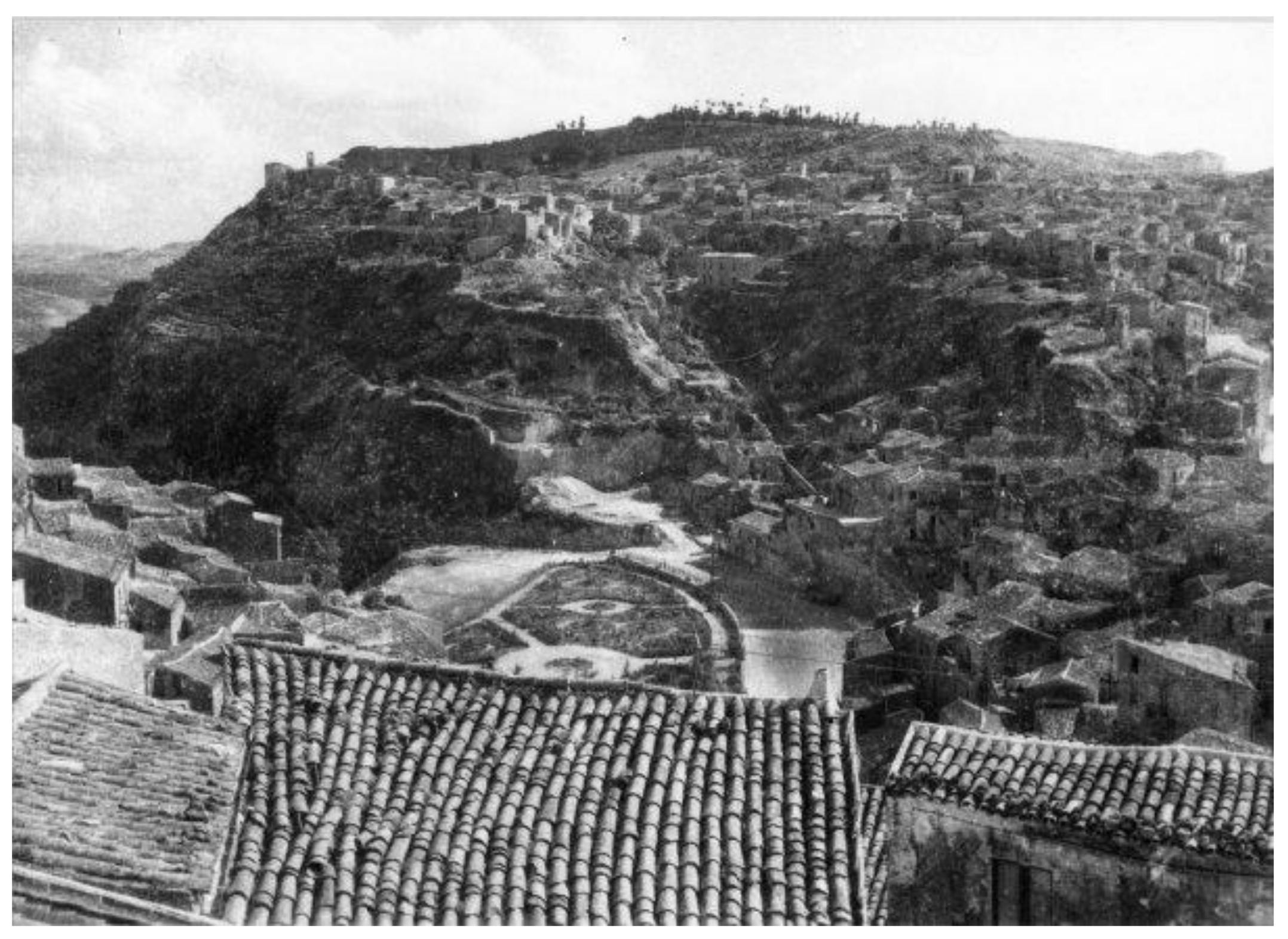
This is also due to the orography of the land, with the historic centre of Enna on a mountain (so-called “Enna Alta”) and a consequent expansion of the city downstream (“Enna Bassa”), as shown in Figure 1, dating back to 1950.
However, this expansion has in part caused the abandonment of some buildings in the historic centre.
Many people preferred to move to new buildings better suited to current housing needs.
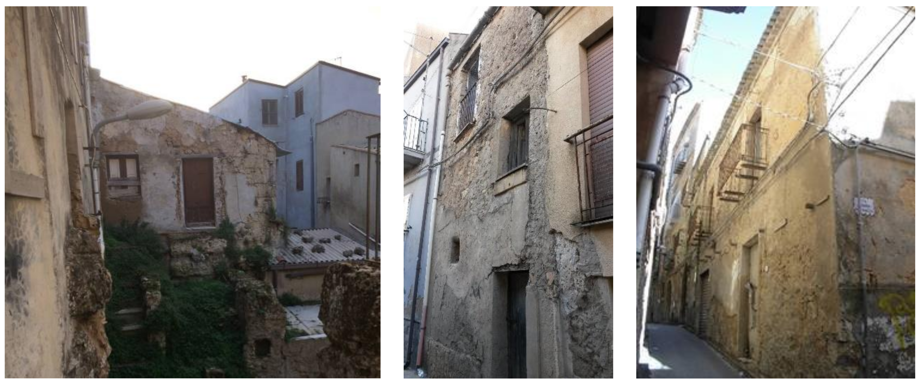
The lack of use of most building in the historic centre eventually caused partial collapses (Figure 2).
The last census of residential buildings in Enna showed 4791 buildings, of which 3376 were built with load-bearing masonry (937 were in a bad condition, partly abandoned, while 144 were in complete decay and abandonment) before 1970, thus without anti-seismic criteria [25].
From the historic urban fabric of Enna, four case studies were identified with different morphological, typological and construction characteristics. The buildings were chosen in the historical fabric of “Enna Alta”.
The typological analysis followed a procedure that considered only the morphological characteristics detectable from the outside and from the cartography [26].
The survey started with research into archival documents on related similar studies and on the contribution made by the present and past urban plans. In particular, we followed the same method of subdivision into building types used by the Detailed and Recovery Plans of the Municipality of Enna from 1990.
The urban morphology of the historic centre of Enna is very complex. Its urban fabric is characterized by a great variety of building types, presenting very different configurations within the different urban meshes in which they are set.
The building types that can be found are linked to the urban hierarchy deriving from the road relationship and the morphology of the site, distinguishing buildings of “major” and “minor” importance.
According to this hierarchy, terraced buildings of considerable consistency were found, overlooking the main streets and monumental buildings (churches, convents and noble palaces) or the squares.
In addition, along the cross streets of the main axes and behind the squares, other significant building typologies were identified: “corner buildings”, almost exclusively single-family, “at court” and some cases of “tower” houses.
Excluding the recent and large volume residential buildings (4–6 floors), present in a limited number, residential buildings are characterized by buildings with two or three levels above ground.
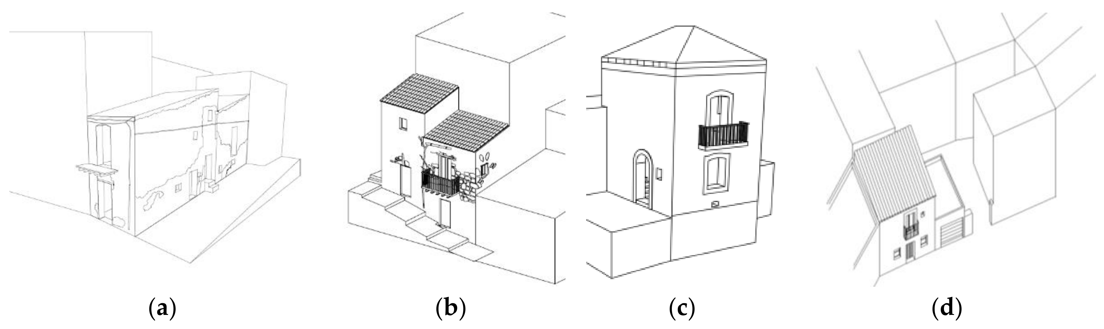
In order to gain knowledge of the typology examined, axonometric schemes were produced reproducing the fundamental aspects of the four building types: a corner building (Figure 3a), terraced building (Figure 3b), tower building (Figure 3c) and at court building (Figure 3d).
From these schemes, such characteristics emerge as, for example, the ratio between horizontal and vertical development, the division into living cells and the contiguity between the buildings.
Plans and schematic sections were produced, showing how the typology is generally inserted within the urban fabric and whether, usually, this type is placed inside or on the front portion of a building block, whether it has a courtyard or not and whether it faces a road axis.
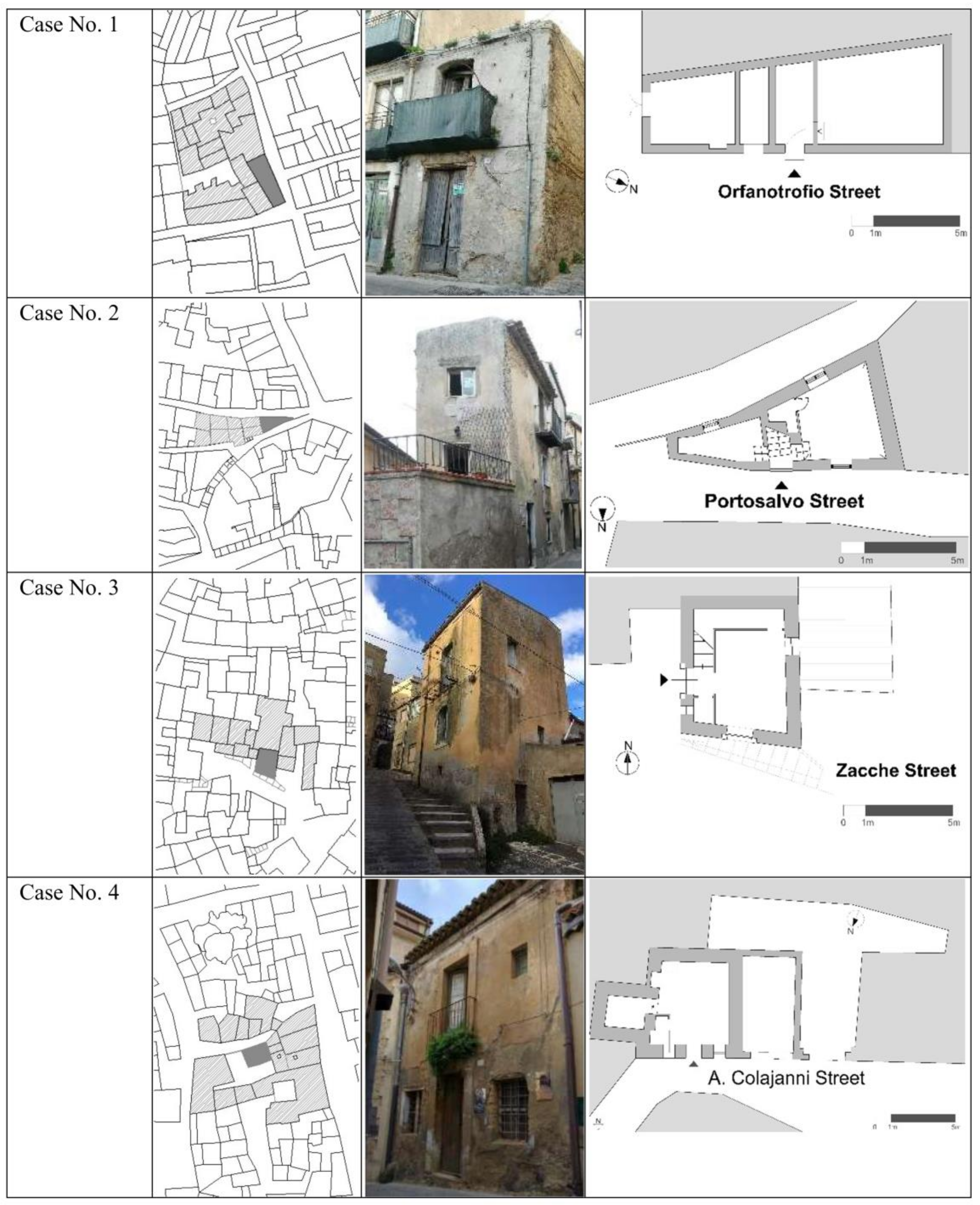
The selected case studies are representative of the following types (Figure 4):
- Corner building: a building consisting of the union of two contiguous living cells, placed at the corner of a quarter, constituted by irregular plots. The plots at the rear saturated the space. (Case No. 1 located in Orfanotrofio St.).
- Terraced building: the building is placed on the front portion of a building block (Case No. 2 located in Portosalvo St.).
- Tower building: the building is defined by its height and it breaks the alignment of the block to which it belongs. It is characterized by one single room for each floor, all connected by stairs to each other (Case No. 3 located in Zacche St.).
- At court building: the building is set on the edge of a “court” building block (Case No. 4 located in Colajanni St.).
As is common for Italian minor centres, Enna is characterized by a spontaneous “architecture without architects” style [27] developed by local builders, according to local topography and climate.
These were mainly built between the end of the 19th century and the beginning of the 20th century [28], with load-bearing masonry (mainly irregular stones), girder and hollow brick floors or wooden beams with gypsum vaults floors and wooden roofing. All the buildings selected were not currently in use and in a state of abandonment [29].
In relation to the size and shape of the stone elements and the quality of the mortar and the stone, the walls present several textures with different strengths, lacking an effective connection between them and the horizontal elements. In addition, floors and roofing mainly made of iron and wooden elements have low in-plane stiffness and strength. These buildings have very limited resistance to seismic actions for both horizontal stresses in the masonry (shears stress) and out-of-plane (buckling stress), therefore requiring seismic retrofitting. Besides, the lack of structural integrity due to a poor connection between structural elements is one of the main causes of earthquake damage in vernacular buildings, where the “box-behaviour” is not guaranteed [13].
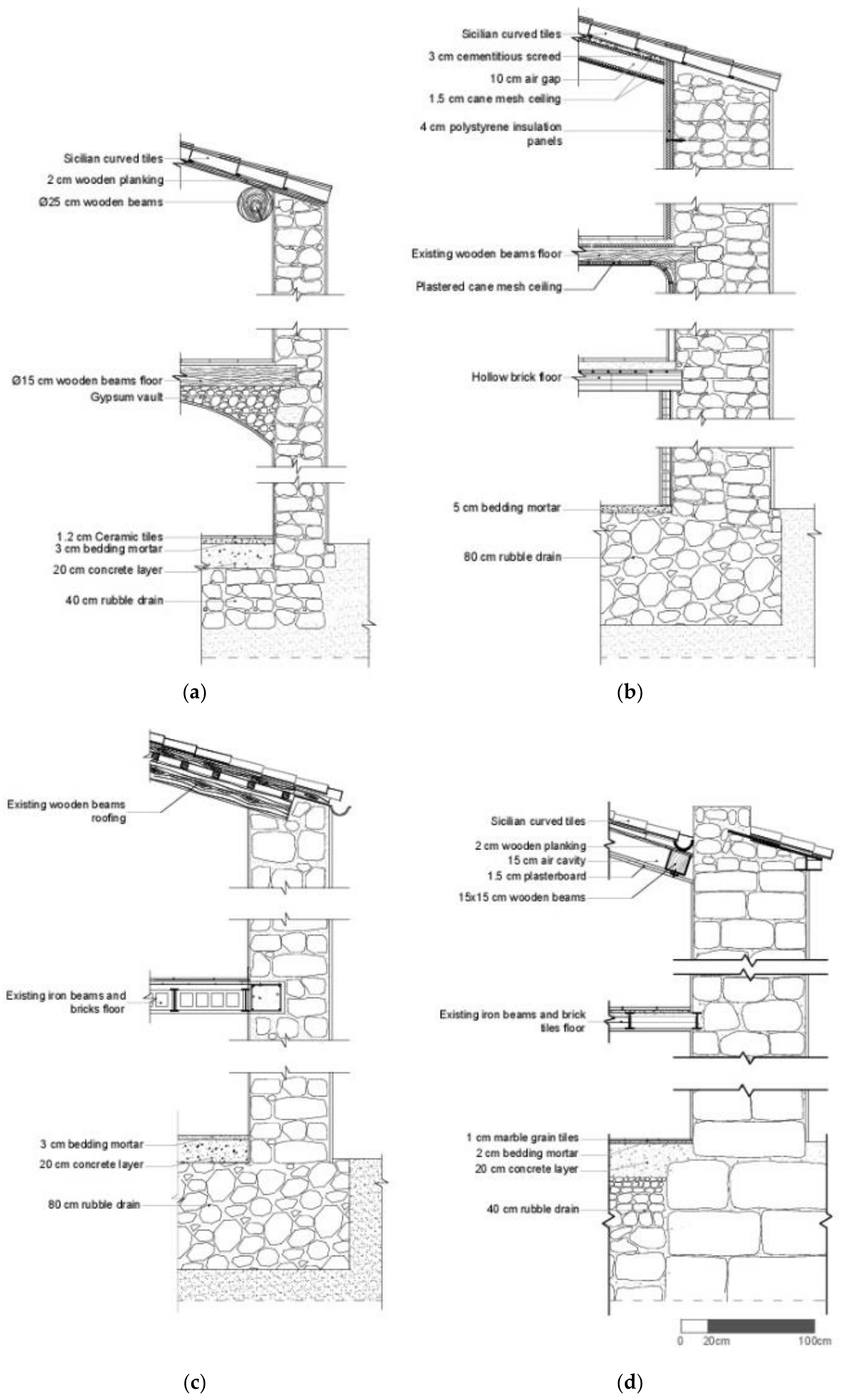
The Case No. 1 building is in a state of abandonment and presents the partial collapse of the roof and floors. It consists of load-bearing irregular stone masonry, consisting of 34 cm for external walls and 20 cm for internal walls, finished outside with 2 cm cement-based plaster and inside with 1.5 cm gypsum plaster, wooden floors with gypsum vaults, according to traditional construction techniques. It has non-thrusting roofs with wooden beams arranged parallel to the eave line, completed with planks and curved tile roofing as shown in Figure 5a.
The Case No. 2 building is in a good state of conservation and has undergone some energy improvement interventions in recent years. It is also made of irregular stone load-bearing masonry with an average thickness of 70 cm, with an insulating inner layer made of 4 cm extruded polystyrene panels, an internal finish of 1.5 cm gypsum plaster and an external finish of 2 cm hydraulic lime plaster. The first floor was rebuilt in the 70s and is a hollow brick floor. The internal space is divided into three levels, one of which is the basement, and the two original floors consist of wooden beam floors to support the bedding mortar and the flooring; the intrados are plain with a cane mesh ceiling finished with plaster mortar. A similar construction technique with wooden beams and an upper and lower layer of 1.5 cm cane mesh was found in the roof, finished with Sicilian curved roof tiles, as shown in Figure 5b.
The Case No. 3 building is abandoned and shows collapse of the inter-floor slab. The load-bearing structure is made of irregular stonewalls, 60 cm thick, finished externally with hydraulic lime mortar and internally with gypsum plaster. The inter-floor slab is made of iron beams and bricks, the roof of wooden beams, joists and Sicilian curved tiles as shown in Figure 5c.
The Case No. 4 building is in good condition. It shows a load-bearing structure of irregular stone, 85 cm thick, an inter-floor slab with iron beams and brick tiles and a wooden roof, finished with Sicilian curved tiles and wooden beams covered by 1.5 cm of plasterboard as shown in Figure 5d.
All the case studies show similar characteristics: the slope of the roofing is between 35% and 40%, the height of each floor is between 375 cm and 420 cm, and the shape of the interior rooms is polygonal.
In order to develop adequate seismic and energy improvement interventions, static and energy checks were performed accounting for the characteristics of the site—geographical coordinates lat. 37.34, long. 14.16, seismic zone 2 and climate zone E, degree-day 2.248—identifying the seismic risk class and the energy class.
3. Results
3.1. Seismic Analysis
For the case studies analysed, the simplified method was applied for the calculation of the seismic risk class, suitable for masonry buildings, considering the PAM parameter.
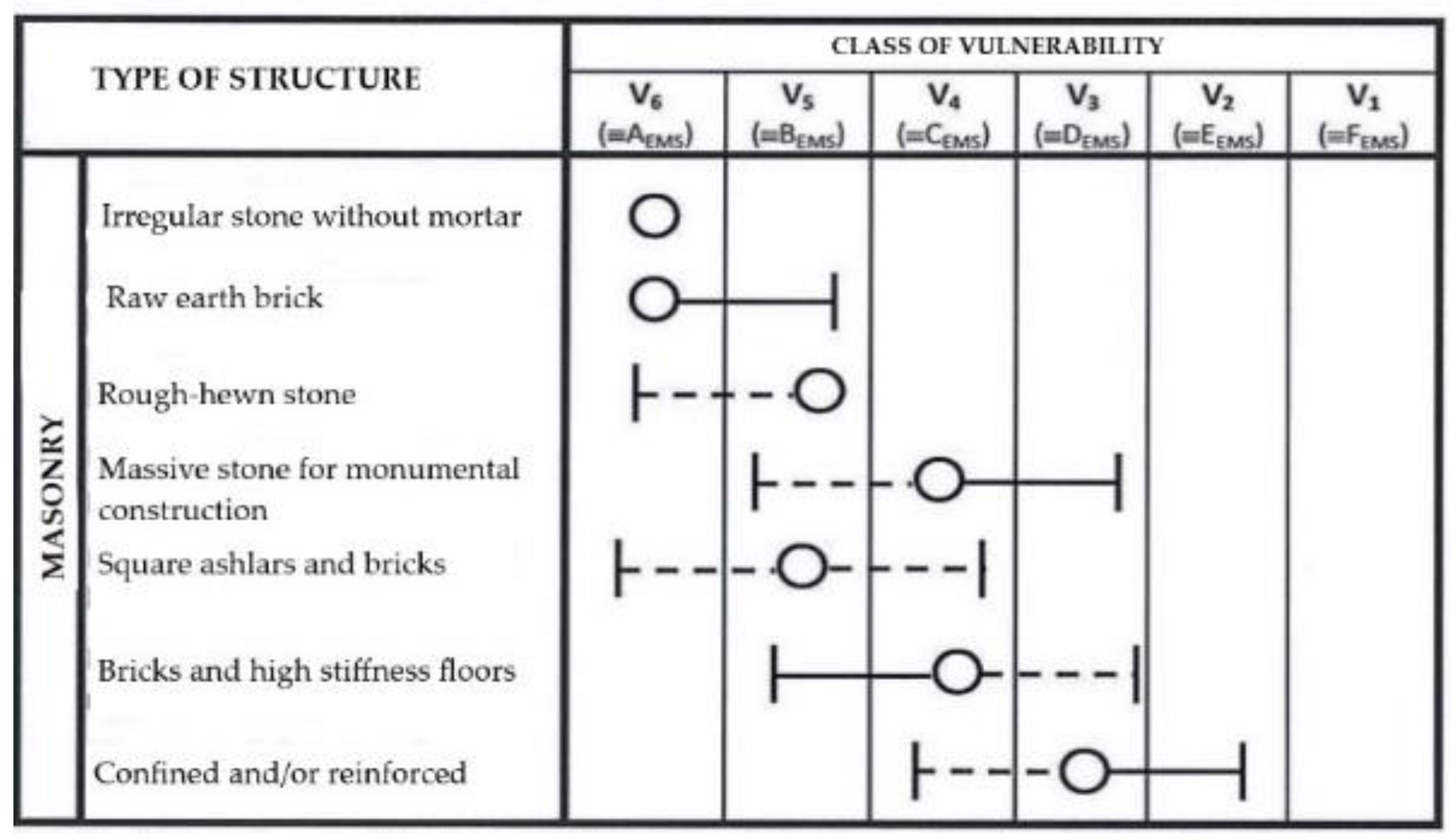
For each case study, by applying the guidelines the vulnerability class of the structure was identified based on the European Macro-Seismic Scale (EMS), which includes six classes of vulnerability from V1 to V6, based on the type of masonry, as reported in Figure 6. In all the four case studies, based on “irregular stone masonry”, the most probable class of vulnerability (mean class) is V5. However, in cases No. 1 and No. 3, there is a deviation from the mean class with an increase in vulnerability to V6, due to the conditions of high degradation and collapse (collapse of the floors and part of the roof).
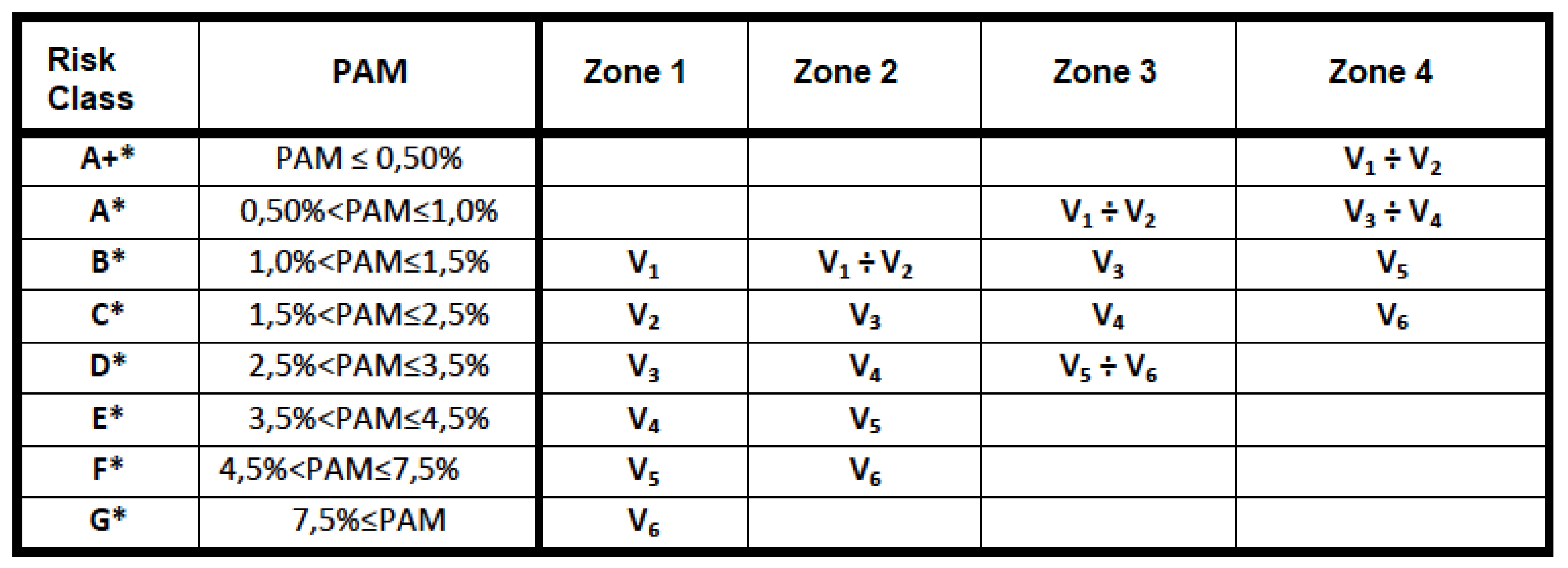
By relating the vulnerability class and the danger of Enna’s location (seismic zone 2), the seismic risk class was defined among the eight classes provided by the guidelines. According to the table of guidelines shown in Figure 7, the buildings of case No. 1 and No. 3 can be classified within the F risk class, while the buildings of cases No. 2 and No. 4 can be classified within risk class E.
From these examples, it is clear that for existing buildings with load-bearing masonry it is not possible to obtain a seismic risk class higher than E or D for areas with high seismic risk, not adding into the calculation the geometric and construction characteristics of the building.
3.2. Energy Analysis
The energy analysis performed before and after the various recovery interventions allowed us to develop optimal energy intervention strategies. From the global thermal analysis, considering the various buildings without winter and summer air conditioning systems and accounting only for the energy required for lighting and domestic hot water, it was found that all the buildings studied were in class G.
Since the buildings in the case studies are single family residences, the energy improvement interventions affect the entire building envelope and therefore a percentage higher than 50% of the gross surface of the entire building.
These interventions fall in the typology defined by the D.M. of 26 June 2015, important first level renovations [30], and therefore the energy performance requirements to be verified concern the entire building.
The verification of the thermo-physical characteristics of the various elements of the building envelope, on the other hand, was useful to identifying the elements where the heat loss was higher, based on the thermal conductivity of every layer, calculated according to UNI 10,351:2015 [31], UNI EN ISO 10,456:2008 [32] and UNI EN ISO 13,370:2008 [33] (Table 2, Table 3, Table 4 and Table 5), and thus guiding the energy regeneration strategies.
Thermal transmittance in the case of the slab-on-ground floor was calculated in accordance with UNI EN ISO 13370:2008:
- , characteristic dimensions of the floor, being A its surface and P its perimeter;
- being the total thickness of walls;
- = 2 W/m2K, the thermal conductivity of ground (sand or gravel);
- = 0.17 m2K/W, the internal superficial thermal resistance for descending flux;
- = the thermal resistance of the floor;
- m2K/W, the external superficial thermal resistance.
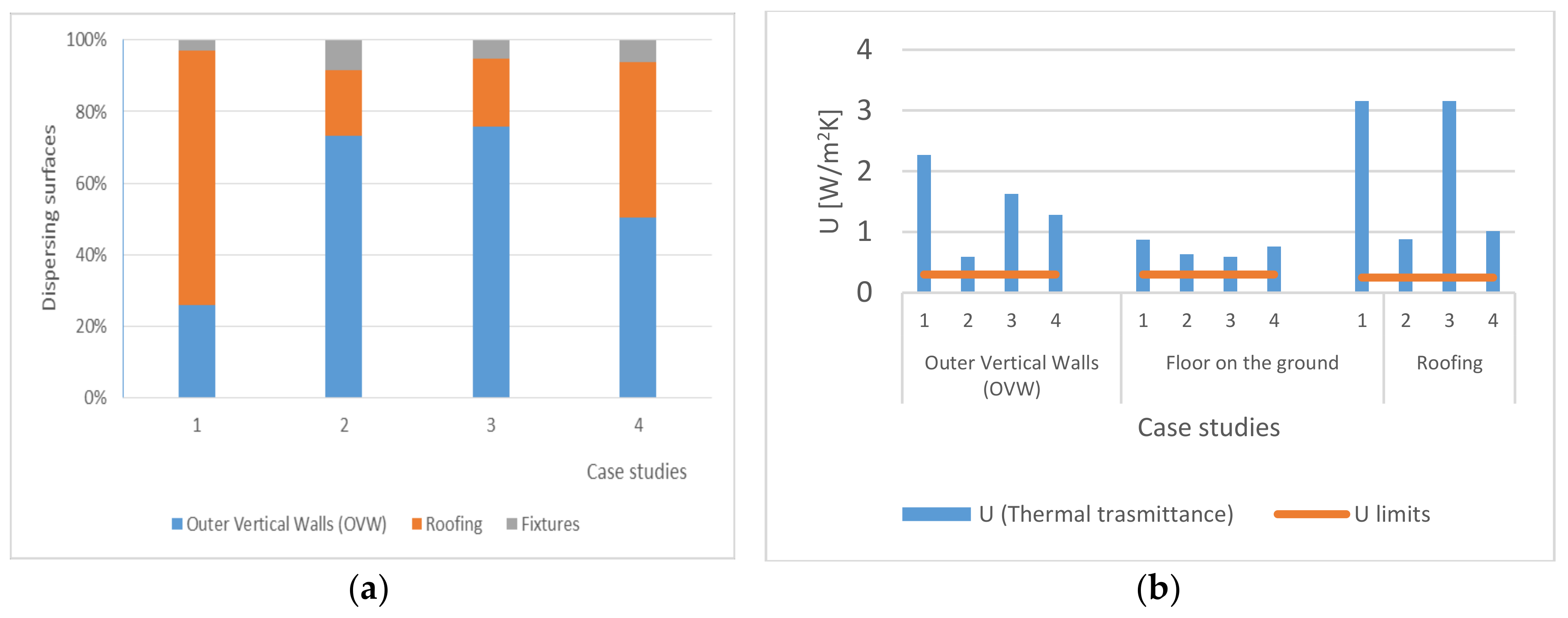
In order to be able to connect the thermal loss to the building types, the surface percentages of the various technical elements of the envelope were calculated with respect to the total surface, as in Figure 8a.
The reduced percentage of door and window surfaces between 3% and 8%, typical of traditional buildings of historic centres, which should make it possible to consider them negligible for the calculation of thermal transmittance.
Calculations show that under more unfavourable conditions, the increase found—considering the thermal input of doors and windows—never exceeded 2.21%.
From the comparison of the thermal transmittances obtained for the various technical elements of the envelope with the performance requirements, according to the current regulations, the thermal transmittance values were found to be considerably higher than the threshold values, as shown in Figure 8b.
The elements with higher heat losses were the roofing (maximum value 3.22 W/m2K for cases No. 1 and 3) exceeding from 4 to 15 times the threshold thermal transmittance, equal to 0.25 W/m2K, and the walls (maximum value 2.25 W/m2K for case No. 1), exceeding from four to seven times the threshold value of 0.3 W/m2K. Only in case No. 2, for the walls (0.61 W/m2K), which exceeded by only two times the threshold value, as this building had experienced energy improvement interventions with internal insulation.
Dealing with the walls of all of the case studies, a reduced thickness determined an increase in thermal transmittance.
The maximum value was U = 2.271 W/m2K, for case No. 1 this was s = 0.375 m. The U percentage reduction for case No. 2 was equal to 73.80%, with an increase in the wall thickness of 106.67%. For case No. 3, the U percentage reduction with respect to case No. 1 was equal to 28.25%, with an increase in the wall thickness of 69.33%. For case No. 4, the U percentage reduction with respect to case No. 1 was equal to 43.57%, with an increase in the wall thickness of 136.00%.
For the floors on the ground, the thermal transmittance was calculated between 0.589 W/m2K and 0.876 W/m2K (according to UNI EN ISO 13370:2008).
3.3. Strategies for Seismic and Energy Improvement of Historical Buildings
Once the risk class of the case studies was defined, it was possible to evaluate any risk improvement and mitigation measures. However, using the simplified method it was possible to choose only local interventions, which do not produce substantial changes in the behaviour of the structure as a whole, addressing only the passage to the higher risk class.
Following the indications of the interventions provided in the guidelines, on the basis of similar solutions adopted in other European countries [36] and the findings regarding recent seismic events in central Italy, a list of possible actions for the case studies analysed was derived (Table 6). These seismic improvement interventions are directed to pursue an overall “box” behaviour, which eliminates or rather reduces local mechanisms outside the plane of the walls. Thus, these interventions aimed at the improvement of the relative mechanical resistance and the strengthening of mutual connections between them and the horizontal elements (floors and roofs).
The interventions on the walls consisted of the improvement of the mechanical strength in two ways: consolidation by means of mortar injections or glass fibre reinforced polymer (GRFP) net and hydraulic lime or thermally insulating mortar (with perlite or polystyrene), 3 cm thick [37].
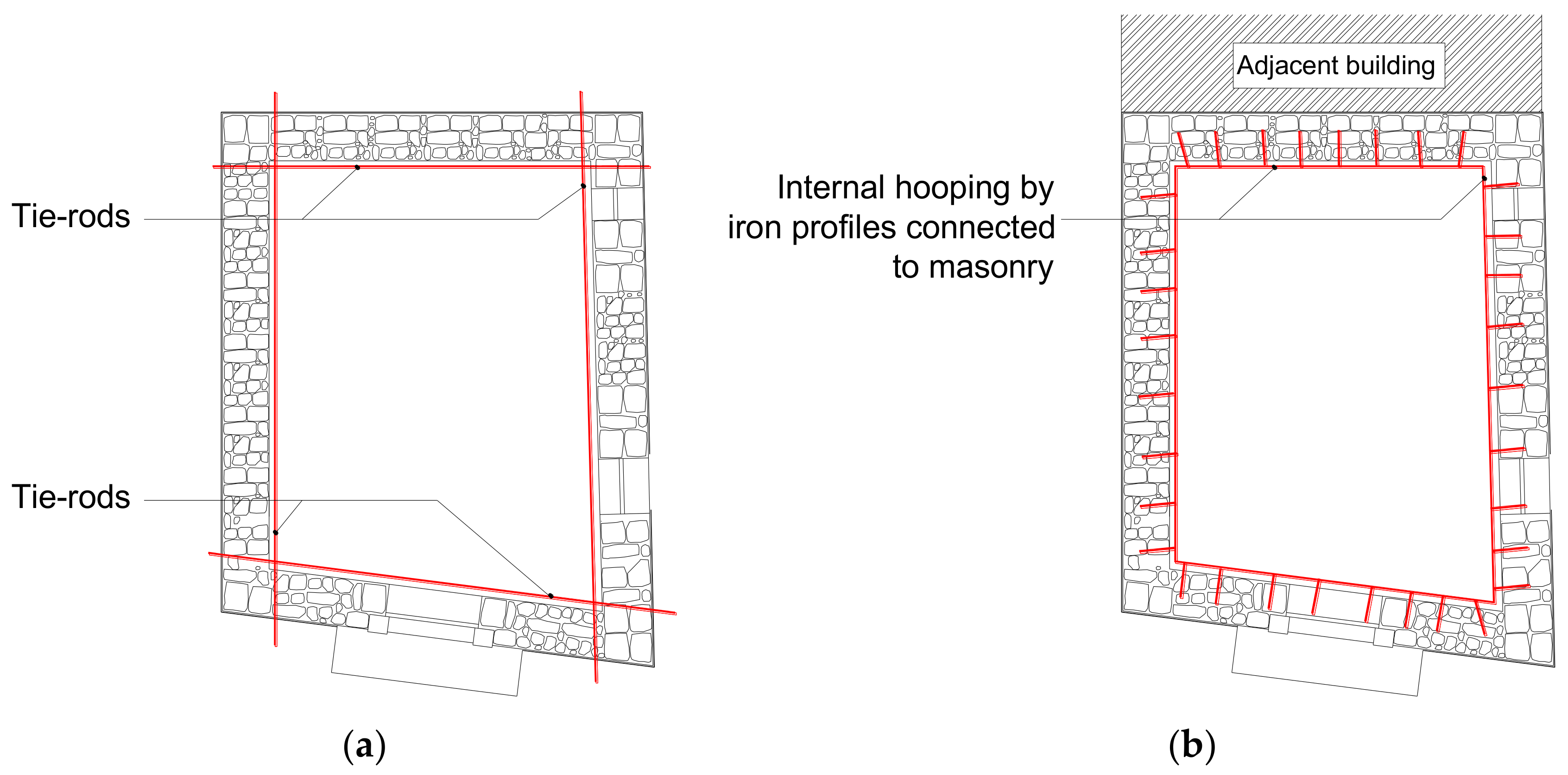
To increase the wall-to-wall connection, tie-rods were considered on both sides of the wall (Figure 9a), while in the case of adjacent buildings, the solution chosen was the realization of an internal iron hooting (Figure 9b). The effectiveness of the tie-rods connecting the walls to each other was also demonstrated by the analysis of the damage undergone by a building in L’Aquila during the 2009 earthquake, since it was a seismic retrofit intervention in 2003, as demonstrated in the study by Lucibello [38].
Interventions on the floor depend on its static conditions. If in good status, the intervention consists of the stiffening of the existing floor and the connection with the load-bearing walls. Steel ties are the recommended intervention. The intervention with steel ties is less invasive, not requiring the demolition of the existing pavement, as reported by Branco and Guerreiro [39].
Chaining with steel profiles, moreover, has been implemented every time it has been necessary to reconstruct floors or roofing, with glued laminated timber or cross-laminated timber panels. These “C” or “L” steel profiles make it easier to set up new floors as well as creating a connection between vertical and horizontal elements. The connection between parallel walls and the floor/roof, using steel plates and wooden beams as connecting elements is one of the techniques of seismic reinforcement proposed by Diz and Costa for supporting masonry buildings in the Azores [40].
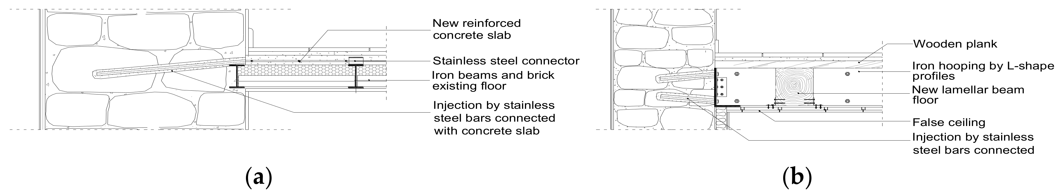
In the case of the maintenance of existing steel floors, stiffening interventions have been provided from the extrados by means of reinforced concrete slabs, connected to the masonry through injections with stainless steel bars (Figure 10a).
All the selected interventions were compatible with the chemical–physical characteristics of natural stone materials and were in most cases reversible [41,42,43].
Otherwise, the reconstruction of the floor is provided for with lamellar wood beams or cross-laminated timber panels, both making a connection to the walls with steel profiles (Figure 10b).
The lamellar wood beams reproduce the original static scheme, which also acts as a chaining, facilitating its installation; the cross-laminated timber panels ensure greater stiffness of the plane.
Interventions into roofing consist of the stiffening of the existing roof with steel tie-rods in the intrados and its connection with the masonry through similar interventions to those proposed for the floors or the steel or reinforced brick bond-beam with steel tie-rods or carbon fibre in the case of roofing reconstruction.
The results of the energy analysis demonstrated the need for energy improvement. Considering the climatic conditions of the place, it was more important to provide interventions to reduce consumption related to winter heating. Excluding an intervention on the plant, only passive insulation measures (internal and/or external) of the envelope with traditional and innovative materials, with high-energy performance and small dimensions were considered.
In order to provide optimal energy performance intervention strategies [44], checks and calculations were carried out, through the combination of the following four interventions on the insulation of external walls, roofing and slab-on-ground floor, doors and windows.
From the various simulations performed for the four case studies, the best performance was found to occur either on the walls or the roofing or both, in relation to the percentage extension of one or the other with respect to the entire surface.
Dealing with energy interventions on walls, the choice between external and internal insulation was basically dictated by the presence or absence of the external plaster or any stone elements in the façade, as it was permitted to intervene from the outside if the building was finished by plaster.
It was preferred, if possible, to use the system with the external insulation, guaranteeing better living comfort both in summer and in winter.
The choice of the insulating materials, using the current technological solutions available, was carried out in compliance with the studies carried out by De Bernardis on a series of buildings in Abruzzo with characteristics similar to those of Enna [15].
From these studies we found that there were about 50% energy savings using vacuum insulation panels (VIP), better set outside than inside; about 44% energy savings using aerogel; about 42% using EPS (extruded expanded polystyrene); and 30% with external TIM (heat reflective materials), considering the same thickness of the insulation material.
For cases No. 1, No. 2 and No. 3, dealing with plastered masonry buildings (λ = 1.3 W/mK), where the walls were available for seismic improvement, an external 12 cm cladding insulation (ʎ = 0.04 W/mK) was provided (cases No. 1 and No. 3), thus enhancing the limits of the law, and 8 cm in addition to the 4 cm existing internal insulation (case No. 2). For case No. 4, due to the presence of fair-faced stone around the doors and windows, a different choice was made.
Internal insulation was provided with 80 mm spray polyurethane foam (λ = 0.035 W/mK) directly to the back of the existing masonry, the application of a 50 mm calcium silicate sheet (λ = 0.094 W/mK) and 20 mm NHL plaster.
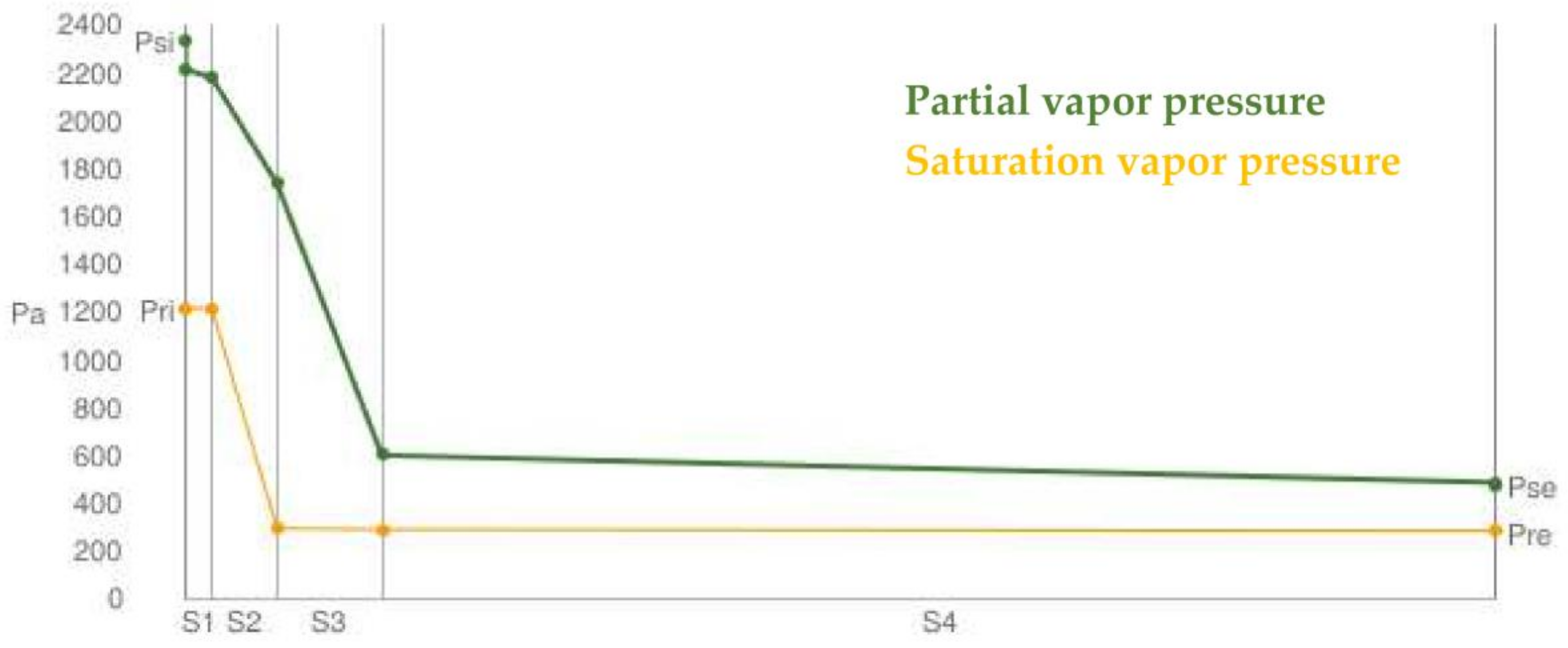
This solution was able to reach the performance standards required by law (U = 0.279 W/m2K) and did not cause condensation problems in winter and mould growth.
To verify this, a calculation by means of a Glaser diagram was performed and Figure 11 shows the results.
This solution was also validated by Straube et al. in a report sponsored by the U.S. Department of Energy [45].
Strategy 1 requires intervention on only one of the four technical elements of the envelope identified (external walls, roofing, floor slab and doors and windows). Strategies 2–4 provide for the combination of two interventions on two technical elements of the envelope. Strategies 5 and 6 provide for the combination of three interventions on the technical elements of the envelope. Table 7 summarizes the six retrofit strategies and for each case study, indicated in subscript, the relative energy class is reported.
In case study No. 1, the best combinations always provide an intervention on the walls. We moved from energy class G, detected in the actual state, to energy class F, by means of only interventions on walls (26%), and to class D by intervening on the walls and roofing (71%), and to class E by intervening on the walls and floors on the ground or on the doors and windows. Combining three interventions between them, in no one case was the energy class higher than D.
In cases No. 2 and No. 3, on the other hand, by only intervening on the walls, it changed from class G in the actual state to class E, since the walls had a high percentage extension over the entire surface (75%). By intervening both on the walls and on any other closing element (roofing, slab-on-ground floor, doors and windows), it passed from class G to D. As regards the combination of several interventions, similar observations can be made to those of case No. 1.
In case No. 4, by only intervening on the walls, it passed from class G to D, and adding an intervention on another element of the envelope did not produce any class increase. Only using strategy 6 was class C obtained.
4. Discussion of the Results
The choice of interventions, accounting for the peculiarities on a case-by-case basis, was made by preferring interventions that involved the same technical element to produce both seismic and energy improvement. By means of the analyses in the previous paragraphs, the elements that showed the best performance were the walls and the roofing.
In fact, the sixth energy strategy, on the basis of the increase in energy class, led to the exclusion of the energy improvement of both the slab-on-ground floor and doors and windows.
For the walls, thin reinforced plaster interventions were planned for walls with limited thickness (30–40 cm), allowing an increase of the shear resistance in the plane and the flexural strength with limited thickness (about 3 cm) reducing the masses and weights on the structure.
For walls between 60 and 80 cm thick, mortar injections were planned to increase the mechanical resistance and the connection of the wall panels to each other by means of steel C-shaped profiles.
Table 8 shows the seismic and energy improvement interventions selected for the various case studies and the related class increases that can be obtained.
5. Conclusions and Future Research Lines
This research proposes a design tool to improve the energy efficiency and the seismic resistance of historic buildings, considering their own architectural value, thus using a “case-by-case” approach.
Through the analysis of the case studies, based on a deep knowledge of their peculiarities, we found that it is possible for existing buildings in the historic centres to develop intervention methodologies on the same technical elements—generally walls and roofing—that combine seismic and energy improvements. These strategies allow the optimization of interventions and above all the possibility to obtain relevant tax relief, combining the two incentives: “sismabonus” (for seismic improvement) and “ecobonus” (for energy improvement) [Italian law No. 205/2017]. While the “sismabonus” is proportionate to the seismic improvement obtained with the intervention, equal to 70% in the case of a single class improvement and 80% for an improvement of two classes, the “ecobonus” refers to the mere total cost of the intervention without accounting for the results of the energy improvement obtained. With the application of the simplified method of the Italian guidelines, we found that for existing masonry buildings, a seismic risk class higher than E or D could not be achieved for areas with high seismic risk, except through the application of the conventional method and the single seismic class improvement, corresponding to the 70% incentive. Besides this, the simplified method for buildings in historic centres is much cheaper than the more conventional and complex method, which only allows an additional 10% financial incentive. It would be desirable that the economic incentive for energy efficiency would be proportionate to the energy class obtained. In particular, the incentive for single-family buildings, as are most buildings in historic centres, would be equivalent to that provided for condominiums that can reach up to 70% for interventions on the envelope with an incidence of more than 25% of the building’s surface, and to 75% for improving winter and summer energy performance. Moreover, the possibility for single-family buildings to obtain credit from banks would also make retraining interventions accessible to low-income people.
Further analysis of other case studies is needed both in the town of Enna and in other historic centres to support this methodology.
Furthermore, the authors consider it important to perform a quantitative seismic analysis, e.g., based on the interpretation of the data provided by the limit states design methods, to verify the real improvement of the seismic class, which is assumed to be superior to that obtained with the qualitative method.
Author Contributions
Conflicts of Interest
The authors declare no conflict of interest.
References
- Available online: https://earthquake.usgs.gov/earthquakes/map/ (accessed on 6 February 2018).
- Legge 2 Febbraio 1974, n. 64. Provvedimenti per le Costruzioni con Particolari Prescrizioni per le Zone Sismiche. Available online: http://www.gazzettaufficiale.it/atto/serie_generale/caricaDettaglioAtto/originario?atto.dataPubblicazioneGazzetta=1974-03-21&atto.codiceRedazionale=074U0064&elenco30giorni=false (accessed on 2 April 2018).
- Cresme Ricerche SpA; Consiglio Nazionale degli Architetti, Pianificatori, Paesaggisti e Conservatori. Chi ha Progettato l’Italia? Ruolo Dell’architettura nella Qualità del Paesaggio Edilizio Italiano; Conferenza Nazionale degli Ordini degli Architetti, Pianificatori, Paesaggisti e Conservatori: Padova, Italy, 2017. [Google Scholar]
- Available online: http://www.europarl.europa.eu/legislative-train/theme-resilient-energy-union-with-a-climate-change-policy/file-energy-efficiency-directive-review/ (accessed on 8 January 2018).
- Available online: https://ec.europa.eu/energy/en/topics/energy-efficiency/buildings (accessed on 19 March 2018).
- Available online: http://www.paesifantasma.it/Paesi/italia.html (accessed on 20 March 2018).
- Available online: http://italia.indettaglio.it/eng/statistiche/statistiche_edilizia.html (accessed on 19 March 2018).
- Maietti, F. Centri Storici Minori: Progetti di Recupero e Restauro del Tessuto Urbano fra Identità Culturale e Salvaguardia; Maggioli Editore: Santarcangelo di Romagna, Italy, 2008; ISBN 978-88-387-4656-7. [Google Scholar]
- Coletta, T. I Centri Storici Minori Abbandonati Della Campania—Conservazione, Recupero e Valorizzazione; Edizioni Scientifiche Italiane: Naples, Italy, 2010; ISBN 9788849520613. [Google Scholar]
- Righi, A.; Dalla Mora, T.; Peron, F.; Romagnoni, P. Historical buildings retrofit he city hall of the city of Motta di Livenza (TV). Energy Procedia 2017, 133, 392–400. [Google Scholar] [CrossRef]
- Nardi, I.; De Rubeis, T.; Taddei, M.; Ambrosini, D.; Sfarra, S. The energy efficiency challenge for a historical building undergone to seismic and energy refurbishment. Energy Procedia 2017, 133, 231–242. [Google Scholar] [CrossRef]
- Brandonisio, G.; Lucibello, G.; Mele, E.; De Luca, A. Damage and performance evaluation of masonry churches in the 2009 L’Aquila earthquake. Eng. Fail. Anal. 2013, 34, 693–714. [Google Scholar] [CrossRef]
- Ortega, J.; Vasconcelosa, G.; Rodrigues, H.; Correia, M.; Lourenco, P.B. Traditional earthquake resistant techniques for vernacular architecture and local seismic cultures: A literature review. J. Cult. Heritage 2017, 27, 181–196. [Google Scholar] [CrossRef]
- Belleri, A.; Marini, A. Does seismic risk affect the environmental impact of existing buildings? Energy Build. 2016, 110, 149–158. [Google Scholar] [CrossRef]
- De Berardinis, P.; Rotilio, M.; Marchionni, C.; Friedman, A. Improving the energy-efficiency of historic masonry buildings. A case-study: A minor centre in the Abruzzo region, Italy. Energy Build. 2014, 80, 415–423. [Google Scholar] [CrossRef]
- Modena, C.; da Porto, F.; Valluzzi, M.R.; Carapezza Guttuso, F.; Iannelli, P.; Rubino, C. Sustainable approaches to the assessment and mitigation of seismic risk and of the effects of earthquake induced damages to historic urban centers. In Proceedings of the 10th International Conference on Structural Analysis of Historical Constructions. Anamnesis, Diagnosis, Therapy, Controls, SAHC 2016, Leuven, Belgium, 13–15 September 2016; Van Balen, K., Verstrynge, E., Eds.; CRC Press: London, UK, 2016; ISBN 9781138029514. [Google Scholar]
- Cardinale, T.; Colapietro, D.; Cardinale, N.; Fatiguso, F. Evaluation of the efficacy of traditional recovery interventions in historical buildings. A new selection methodology. Energy Procedia 2013, 40, 515–524. [Google Scholar] [CrossRef]
- La Greca, P.; Margani, G. Seismic and energy renovation measures for sustainable cities: A critical analysis of the Italian scenario. In Proceedings of the International Conference on Seismic and Energy Renovation for Sustainable Cities, SER4SC, Catania, Italy, 1–3 February 2018; Margani, G., Rodonò, G., Sapienza, V., Eds.; EdicomEdizioni: Gorizia, Italy, 2018; pp. 93–104. ISBN 978-88-96386-56-9. [Google Scholar]
- Available online: http://www.niker.eu/ (accessed on 10 January 2018).
- Vitale, M.R.; Salerno, M.; Billeci, B.; Dessì, M.; Callea, L.; The historical centre of Marignane (France). Survey, diagnostic campaign and structural assessment. In Proceedings of the 10th International Conference on Structural Analysis of Historical Constructions. Anamnesis, Diagnosis, Therapy, Controls, SAHC 2016, Leuven, Belgium, 13–15 September 2016; Van Balen, K., Verstrynge, E., Eds.; CRC Press: London, UK, 2016; ISBN 9781138029514. [Google Scholar]
- Decreto Ministeriale n. 65 del 07/03/2017. Sisma Bonus—Linee Guida per la Classificazione del Rischio Sismico delle Costruzioni e i Relativi Allegati. Modifiche all’articolo 3 del Decreto Ministeriale Numero 58 del 28/02/2017. Available online: http://www.mit.gov.it/normativa/decreto-ministeriale-numero-65-del-07032017 (accessed on 2 April 2018).
- Conseil de l’Europe. Cahiers du Centre Européen de Géodynamique et de Séismologie; European Macroseismic Scale; Grünthal, G., Ed.; Conseil de l’Europe: Strasbourg, Italy, 1998; Volume 15. [Google Scholar]
- UNI/TS 11300-1, Energy Performance of Buildings—Part 1: Evaluation of Energy Need for Space Heating and Cooling; Ente Italiano di Normazione, 2014.
- UNI EN 15243, Ventilation for Buildings—Calculation of Room Temperatures and of Load and Energy for Buildings with Room Conditioning Systems; Ente Italiano di Normazione, 2008.
- Available online: http://italia.indettaglio.it/eng/sicilia/enna.html (accessed on 7 February 2018).
- Santos, C.; Ferreira, T.M.; Vicente, R.; Mendes da Silva, R. Building typologies identification to support risk mitigation at the urban scale. Case study of the old city centre of Seixal, Portugal. J. Cult. Heritage 2013, 14, 449–463. [Google Scholar] [CrossRef]
- May, J.; Reid, A. Architettura Senza Architetti; Rizzoli: Bologna, Italy, 2010; ISBN 9788817037853. [Google Scholar]
- Severino, C.G. Enna. La Città al Centro; Gangemi Editore: Rome, Italy, 1996; ISBN 9788874486816. [Google Scholar]
- Acampa, G.; Campisi, M.T.; Zarbo, I. Fra conservazione e riuso: Strumenti di valutazione per una progettazione critica. In Proceedings of the International Conference on Documentation, Conservation and Recovery of Architectural Heritage and Landscape Protection, ReUSO 2016, Pavia, Italy, 6–8 October 2016; Parrinello, S., Ed.; Edifir-Edizioni Firenze: Florence, Italy, 2016; pp. 284–292. ISBN 978-88-7970-810-4. [Google Scholar]
- Decreto Interministeriale 26 Giugno 2015—Adeguamento Linee Guida Nazionali per la Certificazione Energetica Degli Edifici. Available online: http://www.sviluppoeconomico.gov.it/index.php/it/normativa/decreti-interministeriali/2032968-decreto-interministeriale-26-giugno-2015-adeguamento-linee-guida-nazionali-per-la-certificazione-energetica-degli-edifici.html (accessed on 20 March 2018).
- UNI 10351:2015. Building Materials and Products—Hygrothermal Proprieties—Procedure for Determining the Design Values; UNI, Ente Italiano di Normazione: Milan, Italy, 2015.
- UNI EN ISO 10456:2008. Building Materials and Products—Hygrothermal Properties—Tabulated Design Values and Procedures for Determining Declared and Design Thermal Values; UNI, Ente Italiano di Normazione: Milan, Italy, 2008.
- UNI EN ISO 13370:2008. Thermal Performance of Buildings. Heat Transfer via the Ground. Calculation Methods; UNI, Ente Italiano di Normazione: Milan, Italy, 2008.
- Grabau, A.W. Paleozoic coral reefs. GSA Bull. 1903, 14, 337–352. [Google Scholar] [CrossRef]
- Genova, E.; Kilian, R. Thermal and hygrometric properties of traditional calcarenite stones in the area of Palermo. Energy Procedia 2017, 122, 1081–1086. [Google Scholar] [CrossRef]
- Maio, R.; Estêvão, J.M.C.; Ferreira, T.M.; Vicente, R. The seismic performance of stone masonry buildings in Faial island and the relevance of implementing effective seismic strengthening policies. Eng. Struct. 2017, 141, 41–58. [Google Scholar] [CrossRef]
- Gattesco, N.; Gubana, A.; Melotto, M. GFRP to strengthen masonry walls: Numerical analysis and evaluation of the different mechanical parameters role. In Proceedings of the 10th International Conference on Structural Analysis of Historical Constructions. Anamnesis, Diagnosis, Therapy, Controls, SAHC 2016, Leuven, Belgium, 13–15 September 2016; Van Balen, K., Verstrynge, E., Eds.; CRC Press: London, UK, 2016; ISBN 9781138029514. [Google Scholar]
- Lucibello, G.; Brandonisio, G.; Mele, E.; De Luca, A. Seismic damage and performance of Palazzo Centi after L’Aquila earthquake: A paradigmatic case study of effectiveness of mechanical steel ties. Eng. Fail. Anal. 2013, 34, 407–430. [Google Scholar] [CrossRef]
- Branco, M.; Guerreiro, L.M. Seismic rehabilitation of historical masonry buildings. Eng. Struct. 2011, 33, 1626–1634. [Google Scholar] [CrossRef]
- Diz, S.; Costa, A.; Costa, A.A. Efficiency of strengthening techniques assessed for existing masonry buildings. Eng. Struct. 2015, 101, 205–215. [Google Scholar] [CrossRef]
- Suriya Prakash, S.; Alagusundaramoorthy, P. Behaviour of masonry load bearing walls retrofitted with GFRP composites. J. Struct. Eng. 2009, 36, 397–405. [Google Scholar]
- Sivaraja, S.S.; Thandavamoorthy, T.S.; Vijayakumar, S.; Mosesasaranganathan, S.; Rathnasheela, P.T.; Dasarathy, A.K. GFRP Strengthening and Applications of Unreinforced Masonry wall (UMW). Proc. Eng. 2013, 54, 428–439. [Google Scholar] [CrossRef]
- Proença, J.; Sousa Gago, A.; Cardoso, J.; Cóias, V.; Paula, R. Development of an innovative seismic strengthening technique for traditional load-bearing masonry walls. B Earthq. Eng. 2012, 10, 113–133. [Google Scholar] [CrossRef]
- Penna, P.; Prada, A.; Cappelletti, F.; Gasparella, A. Multi-objectives optimization of Energy Efficiency Measures in existing buildings. Energy Build. 2015, 95, 57–69. [Google Scholar] [CrossRef]
- Straube, J.F.; Ueno, K.; Schumacher, C.J. Measure Guideline: Internal Insulation of Masonry Walls; Building Science Corporation: Somerville, MA, USA, 2012. [Google Scholar]
Figure 1.
View of the historic centre of Enna.

Figure 2.
Examples of abandoned and partially collapsed buildings in the historical centre of Enna.

Figure 3.
Axonometric scheme of the four building types.

Figure 4.
Four case studies in Enna (Sicily).

Figure 5.
Structural cross section of the case studies.

Figure 6.
Class of vulnerability of the structure [21].
Figure 6.
Class of vulnerability of the structure [21].

Figure 7.
Seismic risk class from the Italian guidelines [21].
Figure 7.
Seismic risk class from the Italian guidelines [21].

Figure 8.
(a) Surface percentages of the various technical elements of the envelope on the total surface; (b) Thermal transmittance of the technical elements of the envelope of the considered case studies.
Figure 8.
(a) Surface percentages of the various technical elements of the envelope on the total surface; (b) Thermal transmittance of the technical elements of the envelope of the considered case studies.

Figure 9.
(a) Intervention in an isolated building by tie-rods and (b) on a terraced building by iron hooping.
Figure 9.
(a) Intervention in an isolated building by tie-rods and (b) on a terraced building by iron hooping.

Figure 10.
Connection interventions between walls and slabs.

Figure 11.
Glaser diagram of the proposed retrofit solution for Case No. 4.

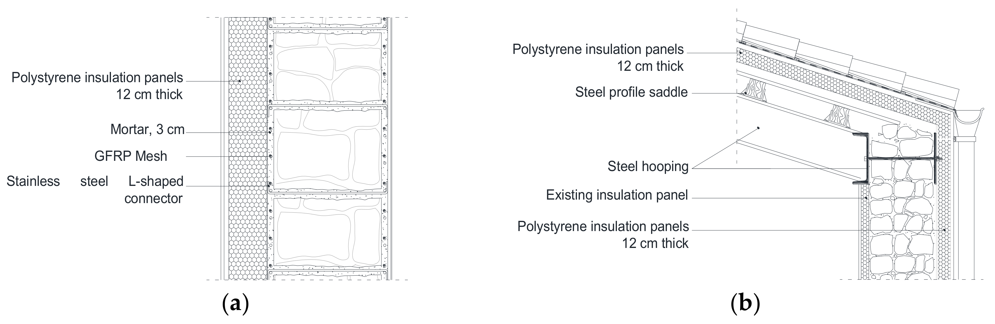
Figure 12.
Detail of seismic and energy interventions on roofing and outer vertical walls (a) Case No. 1; (b) Case No. 2.
Figure 12.
Detail of seismic and energy interventions on roofing and outer vertical walls (a) Case No. 1; (b) Case No. 2.


Table 1.
The most populous cities of Italy with data on residential buildings and abandoned buildings.
Table 1.
The most populous cities of Italy with data on residential buildings and abandoned buildings.
| Municipality | Population | Residential Buildings | Abandoned Residential Buildings | Abandoned Buildings Percentage |
|---|---|---|---|---|
| Palermo | 672,398 | 44,499 | 2068 | 4.65 |
| Catania | 315,769 | 26,755 | 1272 | 4.75 |
| Reggio Calabria | 182,323 | 26,368 | 2010 | 7.62 |
| Naples | 969,490 | 40,344 | 1107 | 2.74 |
| Rome | 2,874,529 | 107,332 | 2365 | 2.20 |
| Milan | 1,353,467 | 42,628 | 1791 | 4.20 |
| Turin | 885,651 | 35,814 | 1119 | 3.12 |
Table 2.
The layers of the envelope’s elements and their relative thermal resistance for Case No.1.
| Type of Structure | Original Layers | Thickness [m] | λ [W/mK] | R [m2K/W] | U [W/ m2K] |
|---|---|---|---|---|---|
| Façade wall | Internal hydraulic lime and gypsum plaster | 0.015 | 0.70 | 0.021 | |
| Solid brick | 0.340 | 1.30 | 0.226 | ||
| External cement-based plaster | 0.020 | 0.90 | 0.022 | ||
| 0.440 * | 2.271 | ||||
| Roofing | Fir plank | 0.020 | 0.12 | 0.167 | |
| Sicilian curved tiles | 0.010 | 1.00 | 0.010 0.317 ** | 3.158 | |
| Slab-on-ground floor | Ceramic floor tiles | 0.012 | 1.00 | 0.012 | |
| Bedding cementitious mortar | 0.030 | 1.30 | 0.023 | ||
| Concrete layer | 0.200 | 1.90 | 0.100 | ||
| Rubble drain | 0.400 | 1.80 | 0.220 | ||
| 0.355 *** | 0.876 |
* indicates the values of thermal resistance, R, for walls, considering the addition of the superficial internal thermal resistance equal to 0.13 m2K/W and the superficial external thermal resistance equal to 0.04 m2K/W; ** indicates the values of R, for roofing, considering the addition of the superficial internal thermal resistance equal to 0.1 m2K/W and the superficial external thermal resistance equal to 0.04 m2K/W; *** indicates the values of Rf, the thermal resistance of the slab-on-ground floor.
Table 3.
The layers of the envelope’s elements and their relative thermal resistance for Case No.2.
| Type of Structure | Original Layers | Thickness [m] | λ [W/mK] | R [m2K/W] | U [W/ m2K] |
|---|---|---|---|---|---|
| Façade wall | Internal hydraulic lime and gypsum plaster | 0.015 | 0.70 | 0.021 | |
| Extruded polystyrene panels | 0.040 | 0.04 | 1.000 | ||
| Calcarenite irregular stone masonry [34,35] | 0.700 | 1.50 | 0.467 | ||
| External NHL plaster | 0.020 | 0.90 | 0.022 1.680 * | 0.595 | |
| Roofing | Internal hydraulic lime and gypsum plaster | 0.010 | 0.70 | 0.014 | |
| Cane mesh ceiling | 0.015 | 0.06 | 0.273 | ||
| Cavity | 0.100 | 0.25 | 0.400 | ||
| Cane mesh ceiling | 0.015 | 0.06 | 0.273 | ||
| Cementitious screed | 0.030 | 1.30 | 0.023 | ||
| Sicilian curved tiles | 0.010 | 1.00 | 0.010 1.132 ** | 0.883 | |
| Slab-on-ground floor | Bedding cementitious mortar | 0.050 | 1.30 | 0.038 | |
| Rubble drain | 0.800 | 1.80 | 0.444 | ||
| 0.482 *** | 0.638 |
Table 4.
The layers of the envelope’s elements and their relative thermal resistance for Case No.3.
| Type of Structure | Original Layers | Thickness [m] | λ [W/mK] | R [m2K/W] | U [W/ m2K] |
|---|---|---|---|---|---|
| Façade wall | Internal hydraulic lime and gypsum plaster | 0.015 | 0.70 | 0.021 | |
| Calcarenite irregular stone masonry | 0.600 | 1.50 | 0.400 | ||
| External NHL plaster | 0.020 | 0.90 | 0.022 0.614 * | 1.630 | |
| Roofing | Fir plank | 0.020 | 0.12 | 0.167 | |
| Sicilian curved tiles | 0.010 | 1.00 | 0.010 | ||
| 0.317 ** | 3.158 | ||||
| Slab-on-ground floor | Bedding cementitious mortar | 0.030 | 1.30 | 0.023 | |
| Concrete layer | 0.200 | 2.00 | 0.100 | ||
| Rubble drain | 0.800 | 1.80 | 0.444 | ||
| 0.567 *** | 0.589 |
Table 5.
The layers of the envelope’s elements and their relative thermal resistance for Case No.4.
| Type of structure | Original Layers | Thickness [m] | λ [W/mK] | R [m2K/W] | U [W/ m2K] |
|---|---|---|---|---|---|
| Façade wall | Internal hydraulic lime and gypsum plaster | 0.015 | 0.70 | 0.021 | |
| Calcarenite irregular stone masonry | 0.850 | 1.50 | 0.567 | ||
| External NHL plaster | 0.020 | 0.90 | 0.022 0.780 * | 1.282 | |
| Roofing | Plasterboard false ceiling | 0.015 | 0.21 | 0.071 | |
| Cavity | 0.015 | 0.25 | 0.600 | ||
| Fir plank | 0.020 | 0.12 | 0.167 | ||
| Sicilian curved tiles | 0.010 | 1.00 | 0.010 | ||
| 0.988 ** | 1.012 | ||||
| Slab-on-ground floor | Marble grain floor tiles | 0.010 | 2.80 | 0.004 | |
| Bedding cementitious mortar | 0.020 | 1.30 | 0.015 | ||
| Concrete layer | 0.200 | 2.00 | 0.100 | ||
| Rubble drain | 0.400 | 1.80 | 0.222 | ||
| 0.337 *** | 0.762 |
Table 6.
Possible actions provided for the selected case studies.
| Site of Intervention | Retrofit Solution | Description |
|---|---|---|
| Walls | SW1 | Mortar injections |
| SW2 | GRFP | |
| SW3 | Wall to wall connection improvement through tie-rods or internal hooping by means of iron profiles | |
| Floors | SF1 | Stiffening and connection with the load-bearing walls |
| SF2 | Reconstruction | |
| Roofing | SR1 | Steel or reinforced brick bond-beam with steel tie-rods or carbon fibre |
| SR2 | Stiffening of the existing roof with steel tie-rods in the intrados | |
| SR3 | Connection of the existing roofing with the masonry through tie-rods or internal hooting by means of iron profiles |
Table 7.
Retrofit strategies of the selected case studies and relative energy class.
| Strategy | Walls | Roofing | Slab-on-ground Floor | Doors and Windows |
|---|---|---|---|---|
| 1 | F1 E2 E3 D4 | G1 G2 G3 G4 | G1 G2 G3 G4 | G1 G2 G3 G4 |
| 2 (Walls) | - | D1 D2 D3 D4 | E1 D2 D3 D4 | E1 D2 D3 D4 |
| 3 (Roofing) | D1 D2 D3 D4 | - | G1 G2 G3 G4 | G1 G2 G3 G4 |
| 4 (Slab-on-ground floor) | E1 D2 D3 D4 | G1 G2 G3 G4 | - | G1 G2 G3 G4 |
| 5 (Walls + roofing) | - | - | D1 D2 D3 D4 | D1 D2 D3 D4 |
| 6 (Walls + slab-on-ground floor) | - | D1 D2 D3 D4 | - | E1 D2 D3 C4 |
Table 8.
Seismic and energy improvement interventions.
| Case Studies | Seismic Improvement Interventions | Energy Improvement Intervention | Seismic Risk Class | Energy Class |
|---|---|---|---|---|
| No. 1 | SW2 SR3 | External insulation, 12 cm thick, and ʎ = 0.04 W/mk Roofing insulation, 15 cm thick, and ʎ = 0.04 W/mk (Figure 12a) | ||
| No. 2 | SW1 SR2 | External insulation, 8 cm thick, and ʎ = 0.04 W/mk and integration of internal insulation, 4 cm thick Roofing insulation, 11 cm thick, and ʎ = 0.04 W/mk (Figure 12b) | ||
| No. 3 | SW1 SW3 SR2 | External insulation, 12 cm thick, and ʎ = 0.04 W/mk Roofing insulation, 15 cm thick, and ʎ = 0.04 W/mk | ||
| No. 4 | SW1 SR1 | Internal insulation, 8 cm thick SPF, and ʎ = 0.035 W/mk + 5 cm thick calcium silicate sheet, and ʎ = 0.094 W/mk Roofing insulation from outside or intrados with insulation, 12 cm thick, and ʎ = 0.04 W/mk |
© 2018 by the authors. Licensee MDPI, Basel, Switzerland. This article is an open access article distributed under the terms and conditions of the Creative Commons Attribution (CC BY) license (http://creativecommons.org/licenses/by/4.0/).
Share and Cite
MDPI and ACS Style
Basiricò, T.; Enea, D. Seismic and Energy Retrofit of the Historic Urban Fabric of Enna (Italy). Sustainability 2018, 10, 1138. https://doi.org/10.3390/su10041138
AMA Style
Basiricò T, Enea D. Seismic and Energy Retrofit of the Historic Urban Fabric of Enna (Italy). Sustainability. 2018; 10(4):1138. https://doi.org/10.3390/su10041138
Chicago/Turabian StyleBasiricò, Tiziana, and Daniele Enea. 2018. "Seismic and Energy Retrofit of the Historic Urban Fabric of Enna (Italy)" Sustainability 10, no. 4: 1138. https://doi.org/10.3390/su10041138
Note that from the first issue of 2016, this journal uses article numbers instead of page numbers. See further details here.