A Novel Dynamic Insulation System for Windows


NTNU, Faculty of Architecture and Design,Wellington 6011, New Zealand
*
Author to whom correspondence should be addressed.
Sustainability 2018, 10(8), 2907; https://doi.org/10.3390/su10082907
Submission received: 11 July 2018
/
Revised: 7 August 2018
/
Accepted: 13 August 2018
/
Published: 16 August 2018
(This article belongs to the Special Issue Advanced Innovative Solutions for Final Design in Terms of Energy Sustainability of Nearly/Net Zero Energy Buildings (nZEB))
Abstract
:One of the measures to reduce energy consumption in buildings in Nordic countries is limiting the window area, as windows contribute to significantly higher heat loss than walls during a long hot season. This conflicts with user needs for daylight and views out, especially in buildings situated in dense urban areas. The purpose of the project was to test if dynamic insulation can be used to reduce heat loss through windows during periods when view out is not needed. The paper presents a new dynamic insulation system for windows in a form of an exterior sliding shutter. The development of the system started from an existing poorly insulating sliding door system that has been equipped with vacuum insulation panels and re-designed according to the new purpose. The new system was both numerically simulated using THERM and tested in full-scale in a Hot-box apparatus at the laboratory of SINTEF Building and Infrastructure. The results are promising and encourage further development towards a commercial product.
1. Introduction
A highly insulated envelope is a prerequisite in cold Nordic climate to reduce energy loss and thereby minimizing heating demand in order to improve the energy performance of buildings. While the insulation thickness of opaque building elements can be easily increased to meet new requirements, thermal performance of windows is relatively limited and windows account for a large portion of heat loss of the building [1].
In order to improve the thermal performance, improvements to the window system comprising glazing, frame and possibly shading, are proposed. Jelle et al. [2] provide an overview of potential strategies for the further development of fenestration. However, proposed measures to increase thermal insulation for insulating glazing units (IGU) and frames such as low emissivity coatings, better cavity fillings, improved spacers and frame constructions are mostly standard in state-of-the-art windows in moderate and cold climates. Other mentioned improvements such as aerogel, PCM (phase change materials), transparent insulation materials, or vacuum glazing may improve one aspect of fenestration, for example insulation but interfere with other basic window functions such as provision of unobstructed view. As Grynning [3] points out, improvements in thermal performance should not impair other beneficial properties. In fact, many advanced solutions are known and discussed since the 1990s [4] but have not succeeded with market penetration. Consequently, best practice of window systems in a Norwegian context has levelled out at triple-glazing with one or two low-emissivity coatings and warm-edge spacers in sufficiently thick that is insulating window frames to avoid excessive material use and weight, avert difficult handling and mounting and ensure robustness and cost-efficiency [3]. The additional layers applied on glass, as electrochromic, photochromic or even low-emissivity coatings have also impact on spectral transmittance of glazing. Perception of colors in interiors, as well as outdoor colors observed through the glazing with such coatings, changes significantly, something that has a negative consequence for the perceived quality of architectural spaces. It may also compromise the color composition applied in interiors, as some colors appear more or less intense or bright than others [5,6].
Another possibility is considering the window system as responsive building element (RBE) as defined by IEA Annex 44. According to van der Aa [7], RBEs “maintain an appropriate balance between optimum interior conditions and environmental performance by reacting in a controlled and holistic manner to changes in external or internal conditions and to occupant intervention”. Characteristics of RBEs include dynamic behavior, adaptability, the capability to perform different functions and intelligent control. With respect to the thermal performance of window, this can be done by covering the window with a temporary opaque or semi-transparent, insulating device, often called dynamic, movable or night-time insulation. Advanced marked-available systems provide a range of functionalities. Besides the possibility of dynamic insulation, they can provide solar protection to reduce cooling loads or improve visual comfort, integrate elements for natural ventilation, or even integrate heat storage (PCM) and decentralized mechanical ventilation.
Measures to reduce heat loss through openings/apertures are addressed in architecture through all times by mounting additional elements permanently or temporarily on the outside or inside of the opening. Systematic and scientific efforts have been made since the time of increasing awareness of energy issues in 1970s and 1980s. Langdon [8] and Shurcliff [9] present systematizations of various movable insulation elements. Airtightness to avoid convection between window insulating unit, condensation in the in-between space and the need for good control strategies were found to be important parameters in order to achieve an adequate effect. Exemplarily, Ruyssevelt and Littler [10] developed and thoroughly tested a system of insulating roller blind. In addition to confirming the above-mentioned issues, they encountered more practical problems such as choice of mechanisms and materials, overoptimistic tolerances, robustness of parts and mounting of the system, which resulted in poor performance or failure. More recently, and in the Nordic context, Bülow-Hübe and Lundgren [11] performed a theoretical study with energy simulation software on the performance of insulating shutters. They suggest, that in order to achieve significant improvement of present-day highly insulated windows, thermal resistances of the shutters must be bigger than 1 m²K/W. Considering limitations regarding the thickness, this may only be achieved with super-insulating materials such as vacuum insulation panels (VIP). The results highlighted the importance of airtightness. Already small gaps around the shutter system minimized the insulating effect of the window-shutter-system and resulted in little reduction of heating and net energy demand for highly insulated windows. However, a less airtight shutter still improved the thermal performance of poorly insulated windows. Internal shutters did not improve insulation significantly. Generally, most effect of the investigated shutter was connected to its ability to provide solar shading and minimize cooling loads. The study was limited to the IGU and did not investigate the influence of the frame nor was a solution proposed for it. Another question posed is the appropriate control of such shutter system and how this can be provided in practice.
This work investigates the development of a simple dynamic insulation system potentially suited for state-of-the-art highly insulating windows in Nordic climate. Firstly, the system is designed based on requirements found in earlier studies. Secondly, numerical simulations are performed to assess the thermal performance of the developed system and to choose the alternative with most potential for further testing. Thirdly, the system is tested in real scale and the performance compared to the numerical results. Lastly, suggestions for further development are given.
The study is limited to thermal performance under steady-state conditions in a laboratory setup without active deployment of the system. No control strategies, interaction with other processes, or additional features were tested.
2. System Development
Based on the previous studies, requirements for a dynamic insulation system can be summarized:
- High thermal resistance
- Low thermal bridge values regarding insertion of panel in the frame
- Low thermal bridge values regarding fitting the system in the wall construction
- Airtightness
- Little total thickness/integration in facade construction
- Exposure to wind, rain, drainage, sun
- Handling wear and tear due to frequent moving
- Robustness of construction/installation
- Simplicity of construction/costs
- Additional functionalities
These issues must be addressed during the design by the system components: panel, frame, joints, actuators and control. However, since verifying thermal performance was priority in the experiments, actuators for automatic deployment and development of control strategies based on sensor inputs were not included at this stage.
2.1. Components
Figure 1 shows the principal details of the developed system as built.
2.1.1. Frame
Several moving systems were considered. Hinged shutters, roller shutters, folding shutters and so forth, were not deemed good enough, particularly regarding airtightness. On the other hand, sliding door/window systems were considered applicable in terms of drainage, airtightness, water intrusion and wear and tear due to frequent use. Timber and aluminum sliding systems were evaluated. Eventually, an aluminum system was chosen due to smaller frame sizes.
A purpose-built frame profile for the application as dynamic insulation could not be developed within the framework of the project. Therefore, the experiment was drawn on proven technology—a marked-available, simple and slender existing sliding system developed for glazed balconies and interior sliding doors. The chosen system is however poorly insulating with U-values of the frame around 7 W/m²K.
2.1.2. Panel
Vacuum insulation panels (VIP) were chosen for the numerical and laboratory studies due to superior insulating properties, while maintaining thin dimensions. To increase robustness, the VIP is mounted in a sandwich element between two layers of plywood in a rather low-tech manner. VIP with dimensioning thermal conductivity of 0.007 W/mK and typical insulation with thermal conductivity of 0.035 W/mK—for example mineral wool—both with thicknesses of 20 mm and 40 mm have been considered and evaluated in numerical studies. Figure 2 shows the overall design of the panel.
Only standard panel sizes were available that did not match the shutter size. Consequently, gaps were filled with strips of XPS and loose mineral wool, which may slightly impact the insulating capability of the panel.
2.1.3. Joints
The sandwich panel is fixed with glazing beads in the frame like an IGU (see Figure 1). There has been special focus on detailing of the integration of panel and frame to minimize the heat loss linked to the spacers and the poorly insulated frame. Therefore, the outer layer of the sandwich panel is extended over the aluminum frame and the resulting distance between frame and plywood layer is filled with thermal insulation.
Another important detail with respect to thermal bridges and airtightness (and potentially drainage) is the mounting of the system on the facade. The system was only intended as a temporary installation during the experiments. Therefore, the system was only designed to be attached on the outside of the facade in a frame of wooden battens.
It was expected that the mid jamb is crucial to achieve sufficient airtightness. Modified parts of the existing sliding system were utilized. These consist of two elements which interlock to create an airtight joint between closed door leaves. One of these elements was mounted on the outer surface of the wall. In order to achieve good performance, the chosen installation requires a high level of precision.
2.2. Implementation
Originally, the system was designed for field testing, where the system was configured to fit a window of 1170 × 1170 mm (outer frame dimension). This size can be considered common for windows in Nordic conditions. The size of the sliding system was chosen so that no part of the system intrudes a 45° angle from the edge of the glass to disturb access to daylight. The resulting dimension of the outer frame of the sliding system was 2650 × 1300 mm and of the sliding panel 1360 × 1231 mm.
However, the field study was not conducted due to administrative changes in the project and the system was tested instead in the Hot-Box test facility at SINTEF Building and Infrastructure in Trondheim.
3. Numerical Studies
3.1. Method
Numerical studies were performed to assess design aspects and the theoretical thermal performance of the developed system. According to NS-EN ISO 10077-1 [12], the U-value of windows with closed shutters is calculated as:
with:
- UWS
- Thermal transmittance of a window with closed shutter
- UW
- Thermal transmittance of the window without shutter
- ΔR
- Additional thermal resistance due to the air layer between window and shutter and the shutter itself.
ΔR depends on the thermal properties of the shutter and its air permeability. NS-EN 13125 [13] provides the five classes of air permeability of which classes 3 (“average”), 4 (“low”) and 5 (“air tight”) can be considered relevant for the system with respect to the expected gap sizes of the system.
The thermal resistance of the shutter Rsh can be obtained by measurement, or by calculation according to NS-EN ISO 10077-1 and -2 [14], based on the equation for the thermal transmittance of the shutter Ush:
with:
- Ap
- Area of the panel
- Up
- Thermal transmittance of the panel
- Af
- Area of the frame
- Uf
- Thermal transmittance of the frame
- lp
- Length of the panel edge
- Ψp
- Linear thermal transmittance of the panel edge
The calculations were performed with THERM [15]. Appendix A shows the used materials properties and boundary conditions.
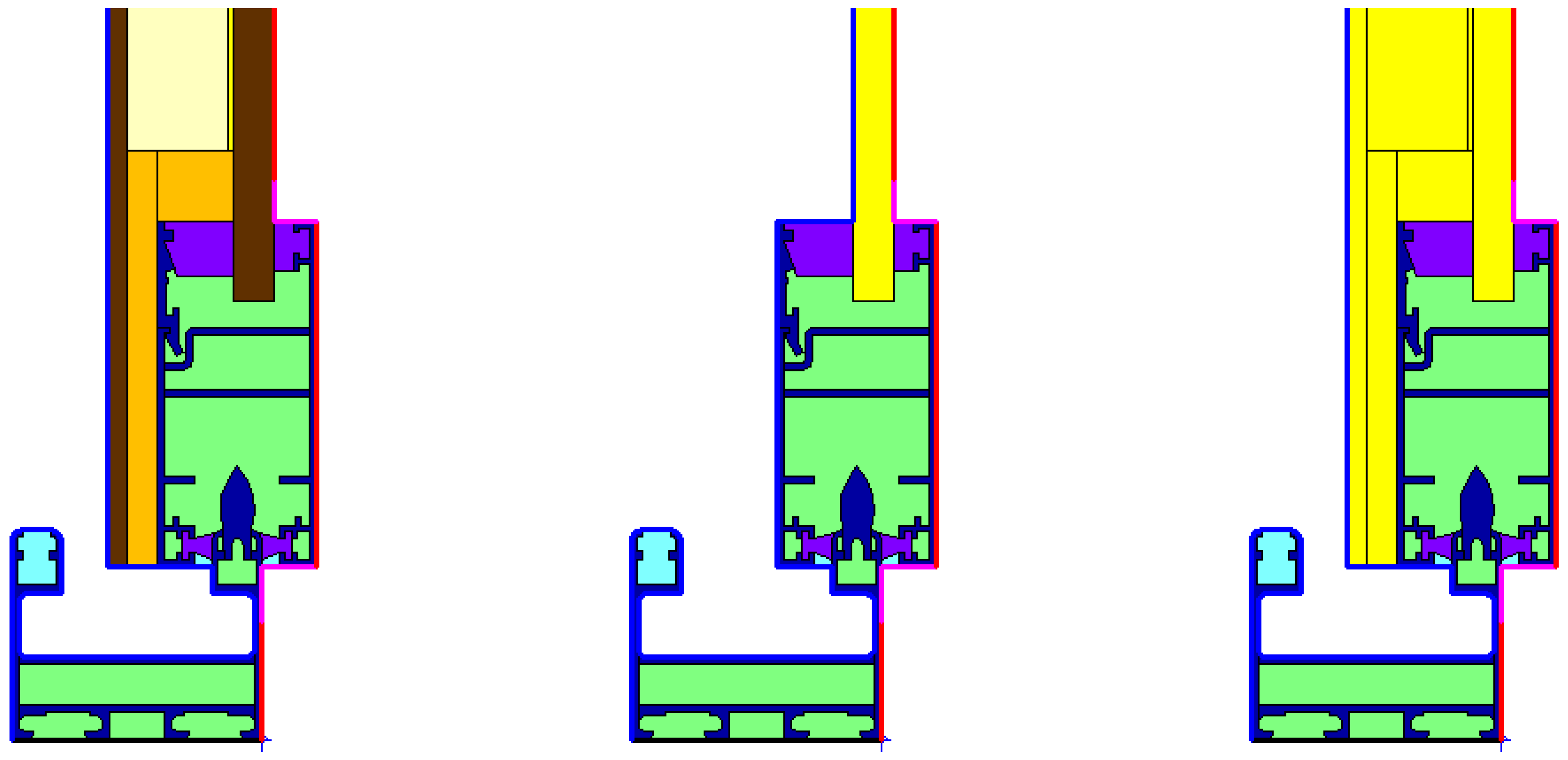
In order to determine Uf and Ψp, the calculation procedure includes simulations with the panel with actual material properties and with a calibration panel, that is, an insulation panel with the same dimensions as the actual panel but a thermal conductivity of 0.035 W/mK. These calculations presume an IGU or panel fixed with a glazing bead within the size of the shutter frame. However, in the present case the sandwich panel extends over the frame. Therefore, two alternatives for modelling the calibration panel were investigated. In method A, the sandwich panel is reduced to the width held by the glazing bead similar to an IGU. In method B, the calibration panel replaces the entire sandwich panel. Figure 3 shows the sill of the shutter as example for the two alternative methods in THERM.
Moreover, the calculation does not consider a difference between window size and shutter size. Figure 4 illustrates the four possible cases: (a) the shutter does not exceed the window, (b) the shutter, both frame and panel, exceeds the window, (c) the shutter frame exceeds the window, (d) the shutter frame exceeds the window partly.
For cases (b), (c) and (d) it can be assumed that the influence of the shutter frame represented by Af will be overestimated in the calculations since the window is more covered by the panel with better insulation properties. Using NS-EN ISO 10077-2 is therefore a conservative approach for the present case, where both jambs correspond to case (b) and head and sill to case (c).
3.2. Results
Table 1 shows a comparison between the results of the two methods for the investigated system. Ush and Rsh are calculated for a size of 1360 × 1300 mm and a shutter panel with 20 mm VIP. “Jamb,r” is the mid jamb of the sliding panel with an effective projected width of zero and without Uf value.
Method B gives slightly better results than method A, results are however comparable. Adding insulation outside the frame, although only 6 mm thick, is evident in both methods, either with negative Ψp-values in method A, or with lower Uf-values in method B and improves the thermal resistance of the poorly insulated frame profiles notably. Generally, the thermal performance of the total system is significantly lower than the super-insulated panel alone due to the negative effect of the poorly insulated frame.
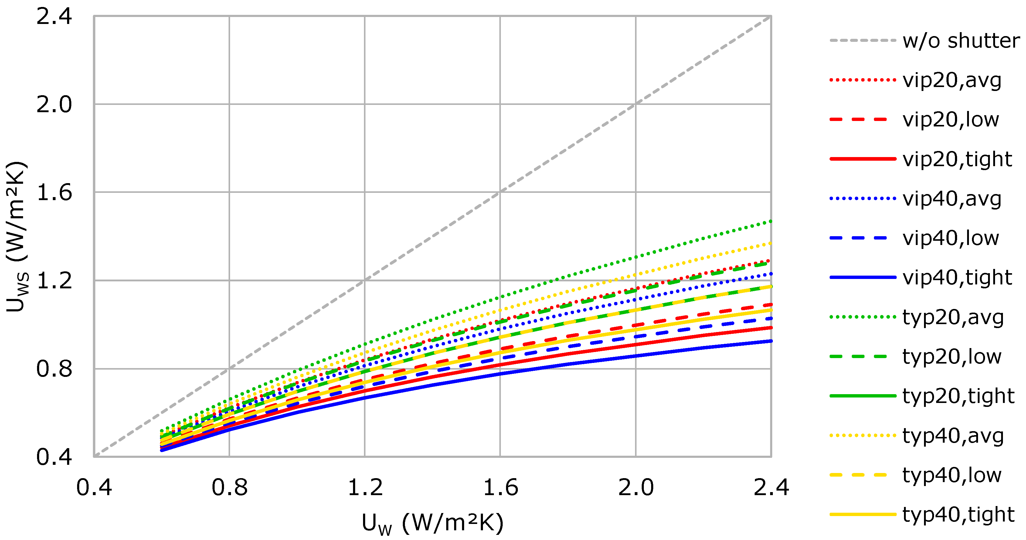
Figure 5 shows the resulting UWS-values for systems with 20 mm VIP panels with Rsh of 0.45 m²K/W. In addition, this base case, results are presented for 40 mm VIP with Rsh of 0.52 m²K/W, 20 mm typical insulation with Rsh of 0.28 m²K/W and 40 mm typical insulation with Rsh of 0.37 m²K/W. As the air permeability class for the system is unknown, results are shown for air permeability classes 3 (“average”), 4 (low”) and 5 (“tight”) to show the expected range.
The expected improvements of the U-value are considerable for the base case with 20 mm VIP, also for highly insulated windows. For common U-values of 1.60, 1.20 and 0.80 W/m²K, the improvement is between 36 to 49%, 30 to 42%, respectively 22 to 32% depending on the air permeability of the system. Generally, the differences between the panel thicknesses and insulation materials are small compared to the influence of the air permeability of the shutter. Differences are only significant for windows with high UW-values and little airtight shutter systems. A mineral wool insulated shutter with the same panel thickness in class “low” can even have a better thermal performance than a vacuum insulated shutter in air permeability class “average”. Therefore, it was decided to continue with the 20 mm VIP in the laboratory tests to achieve best performance.
4. Laboratory Tests
4.1. Set-up
To determine the actual thermal performance, a prototype was built and tested in real scale at the guarded hot box facility of SINTEF Building and Infrastructure according to procedures described in ISO 8990:1994 and ISO 12567-1:2010. The different configurations were measured in two series to reduce systematic uncertainties. Two cases were measured three times due to unexpected results in the first series.
A triple-glazed aluminum frame window was chosen for the test. However, the measurements revealed, that the U-value of the window was not better than 1.98 W/m²K. A second test with a state-of-the-art window with a U-value around 0.8 W/m²K was considered. Unfortunately, such window was not available in the laboratory in the required size. The window was mounted in a template wall constructed as a sandwich element consisting of a 100 mm thick Extruded Polystyrene (XPS) core, clad with 12 mm plywood on the faces exposed to the hot and cold sides.
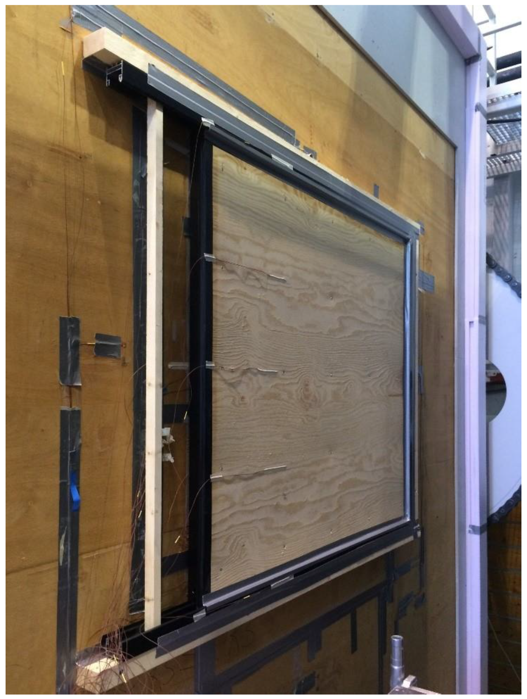
The shutter system was mounted in a frame of battens 73 × 48 mm with taped joints as close to the template wall as possible to avoid convection in the cavity between window and shutter. The system was mounted so that the shutter is placed centered over the window. Figure 6 shows the mounted system in the template wall of the Hot box.
Four test cases were established to investigate the influence of airtightness on the thermal performance of the system (Figure 7):
- “no tape”: the joints between the shutter and sliding system respective walls are not sealed
- “3 sides taped”: the joints between shutter and sliding system are sealed
- “1 side taped”: only the joint to the wall is sealed
- “all sides taped”: all 4 sides of the shutter are sealed
4.2. Results
Table 2 presents the results of the laboratory experiments in the hot box apparatus.
The thermal performance of the window alone is rather poor with a U-value of 1.98 W/m²K but is significantly improved, when the shutter system is mounted. U-values for cases “no tape” and “3 sides taped” are both 0.86 W/m²K. Case “1 side taped” reaches a U-value close to case “all sides taped” with 0.78 W/m²K. The resulting U-values of the cases with shutter are ca. 60% lower than the U-value of the window.
Figure 8 shows a comparison of the experimental results with the numerical study.
Results of the investigated laboratory measurements exceed the results from the numerical studies. Considering the UW-value of the window of 1.98 W/m²K, a U-values with shutter UWS between 0.91 and 1.17 W/m²K was expected depending on the air permeability class. However, measured UWS-values are 6 to 15% lower than expected for a very air tight system.
Noticeably, “1 side tape” and “all sides taped” give better results than the other two cases, indicating that they are more airtight. Comparing case “1 side taped” to cases “3 sides taped” and “all sides taped,” the critical detail appears to be the mid jamb, whereas additional sealing of the other 3 sides shows little improvement. Assuming that cases “no tape” and “3 sides taped” correspond to air permeability class “low” and cases “1 side taped” and “all sides taped” to air permeability class “tight,” then Rsh of the shutter can be estimated to 0.64 m²K/W. These values cannot be reached in numerical calculations even when using new vacuum insulation with a thermal conductivity of 0.004 W/mK (resulting Rsh 0.48 m²K/W), for instance. It is assumed that the difference between calculated and measured U-values is mainly a result of the sliding system extending over the window which is beyond the scope of calculations in NS-EN 10077-1 and -2.
5. Discussion
Numerical and experimental investigations indicate significant improvement of the thermal performance for all types of windows. For state-of-the-art double and triple-glazed windows, U-values are reduced by approximately 40% and 25% respectively. An even larger potential can be foreseen for retrofitting of older windows. For the tested poorly insulated window, an improvement of approximately 60% was reached.
The results verify that the type of frame, detailing of the joints and airtightness of the system are the most critical parameters for thermal performance. The right choice of the frame, that is moving mechanism and frame profiles, is crucial in order to achieve sufficient overall thermal resistance of the shutter. Using a sliding system has proven adequate, as such moving mechanism achieves good airtightness by design. The frame was supposed to be as slim and simple as possible but was therefore poorly insulating and diminished the thermal performance of the entire system. Using a better insulating, thermally broken frame could result in a thicker and more advanced system than desired. However, extending the insulating sandwich panel over the sliding frame profiles improved the thermal resistance of the sliding frame. Despite concerns of an additional thermal bridge and possible air leakage along the edges, no negative effect could be assigned to installing the sliding system in a simple frame of battens.
The laboratory tests with several cases of sealing configurations showed that thermal performance is noticeably improved by better airtightness. However, the experiments also showed that it does require sealing only selected, crucial places, in this case the mid jamb. Results of the laboratory experiments indicate that the reworked interlocking mechanism of the original sliding door system worked sufficiently well to achieve a good level of thermal performance.
On the other hand, little difference between insulation types and thicknesses of the shutter panel was found in the numerical studies. VIP was used in the laboratory experiments but is costly and usually only available in standard panel sizes which can be problematic considering the variety of window sizes. Numerical studies showed that typical insulation materials could achieve good thermal performance as long the system is airtight.
Discrepancies between calculated and measured results show that the calculation procedures in the standards may not cover all aspects of a dynamic insulation system. Further studies should therefore focus on real scale laboratory and field testing.
6. Future Work
From the results of the present studies, the scope for future system design can be outlined:
- The profiles of components should be customized to fit the purpose of a dynamic insulation system. This would also include considerations regarding structural integrity, material strength, drainage and so forth, which is beyond the scope of this project.
- As an alternative to the horizontal sliding system, upward retracting shutters are potentially more airtight as the weight of panel would aid to seal the shutter at the bottom and could work as gradually adjustable shading device.
- Mechanical actuators will need to be integrated in the frame, particularly to allow operation of the system when the room is not occupied.
- A control system including control strategies/algorithms for deployment has to be developed. The challenge is to find the balance between improved thermal performance and reduced solar gains and daylighting. Potentially, sensors should be integrated in the system.
- The environmental impact of system should be considered in a holistic way. A life cycle assessment (LCA) should be conducted to assess if the additional material use for the dynamic insulation system is balanced by potential energy savings.
7. Conclusions
A novel dynamic insulation system has been developed based on an existing poorly insulating sliding door system. The results from laboratory testing are promising and showed improvement of the thermal performance of a poorly insulated window to passive house level. However, more investigation is necessary to test the feasibility for new windows. As the calculation procedures in the relevant standards cannot cover all aspects of such a dynamic insulation system, more laboratory experiments should be conducted with state-of-the-art windows. This would indicate the potential field of application of the dynamic insulation system.
The developed system is still in an experimental state and not market ready. Further development is necessary, both regarding the system design and testing in real scale.
Author Contributions
Conceptualization, B.S.M.; Methodology, B.S.M. and M.G; Software, M.G.; Validation, B.S.M., M.G.; Formal Analysis, M.G.; Investigation, M.G. and B.S.M.; Resources, B.S.M.; Data Curation, M.G.; Writing-Original Draft Preparation, M.G.; Writing-Review & Editing, M.G. and B.S.M.; Visualization, M.G.; Supervision, B.S.M.; Project Administration, B.S.M.; Funding Acquisition, B.S.M.
Acknowledgments
The dynamic insulation system was developed in the frame of the HOME research project, sponsored by the Norwegian Research Council. The authors express their gratitude to colleagues from SINTEF Building and Infrastructure, especially to Egil Rognvik, who performed the testing of the device in the Hot-box, to Schüco Norge for providing the sliding door system and especially Yau Luong for technical assistance and Christian Olavesen at Vacunor for providing the VIP.
Conflicts of Interest
The authors declare no conflict of interest.
Appendix A

Table A1.
Used materials and properties in THERM-simulations.
| Material | Conductivity (W/mK) | Emissivity (−) |
|---|---|---|
| Aluminium alloy, painted | 160.00 | 0.9 |
| EPDM | 0.25 | 0.9 |
| PVC, rigid | 0.17 | 0.9 |
| Mineral wool, loose | 0.035 | 0.9 |
| Mineral wool, stuffed | 0.04 | 0.9 |
| Vacuum insulation | 0.007 | 0.9 |
| Timber | 0.13 | 0.9 |
| Plywood | 0.13 | 0.9 |
| Frame cavity, simplified | … | (0.9) |
| Frame cavity, slightly ventilated | … | (0.9) |
Table A2.
Used boundary conditions (according to NS-EN 10077-1).
| Boundary Condition | Temperature | Surface Transfer Coefficient |
|---|---|---|
| outside | 0 °C | 0.04 m²K/W | 23 W/m²K |
| inside | 20 °C | 0.13 m²K/W | 8 W/m²K |
| inside, reduced | 20 °C | 0.20 m²K/W | 5 W/m²K |
References
- Grynning, S.; Gustavsen, A.; Time, B.; Bjørn Petter, J. Windows in the buildings of tomorrow: Energy losers or energy gainers? Energy Build. 2013, 61, 185–192. [Google Scholar] [CrossRef]
- Jelle, B.P.; Hynd, A.; Gustavsen, A.; Arasteh, D.; Goudey, H.; Hart, R. Fenestration of Today and Tomorrow: A State-of-the-Art Review and Future Opportunities. Sol. Energy Mater. Sol. Cells 2012, 96, 1–28. [Google Scholar] [CrossRef]
- Grynning, S. Transparent Facades in Low Energy Office Buildings—Numerical Simulations and Experimental Studies; NTNU: Trondheim, Norway, 2015. [Google Scholar]
- Schittich, C.; Staib, G.; Balkow, D.; Schuler, M.; Sobek, W. Glasbau Atlas; Birkhäuser: Berlin, Germany, 1998. [Google Scholar]
- Matusiak, B.; Fridell Anter, K.; Angelo, K. Colour Shifts behind Modern Glazing. Available online: https://www.konstfack.se/SYN-TES/ (accessed on 4 December 2012).
- Arbab, S.; Matusiak, B.S.; Martinsen, F.A.; Hauback, B.C. The impact of advanced glazing on colour perception. J. Int. Colour Assoc. 2017, 17, 50–68. [Google Scholar]
- Van der Aa, A.; Heiselberg, P.; Perino, M. Designing with Responsive Building Elements; Aalborg University: Aalborg, Denmark, 2011. [Google Scholar]
- Langdon, W.K. Movable Insulation: A Guide to Reducing Heating and Cooling Losses through the Windows in Your Home; Rodale Press: Paris, France, 1980. [Google Scholar]
- Shurcliff, W.A. Thermal Shutters and Shades: Over 100 Schemes for Reducing Heat Loss Through Windows; Brick House Publishing Co.: Andover, MA, USA, 1980. [Google Scholar]
- Ruyssevelt, P.A.; Littler, J.G.F. Movable Roller Insulation; OPOCE: Luxembourg, 1985. [Google Scholar]
- Bülow-Hübe, H.; Lundgren, M. Fönsterluckor/window shutters. In Proceedings of the 3rd Nordic Passive House Conference on Sustainable Building, Aalborg, Denmark, 7–8 October 2010. [Google Scholar]
- Standard Norge. NS-EN ISO 10077-1:2007 Thermal performance of Windows, Doors and Shutters—Calculation of Thermal Transmittance—Part 1: General; Standard Norge: Lysaker, Norway, 2007. [Google Scholar]
- Standard Norge. NS-EN 13125:2001 Shutters and Blinds—Additional Thermal Resistance—Allocation of a Class of Air Permeability to a Product; Standard Norge: Lysaker, Norway, 2001. [Google Scholar]
- Standard Norge. NS-EN ISO 10077-2 Thermal Performance of Windows, Doors and Shutters—Calculation of Thermal Transmittance—Part 2: Numerical Method for Frames; Standard Norge: Lysaker, Norway, 2012. [Google Scholar]
- LBNL. THERM; Lawrence Berkeley National Laboratory (LBNL): Berkeley, CA, USA, 2014. [Google Scholar]
Figure 1.
Vertical and horizontal sections through the system as built for the laboratory test.

Figure 2.
Construction of the shutter panel (VIP marked with grey).

Figure 3.
THERM model with actual panel materials (left), with calibration panel according to method A (centre), and with calibration panel according to method B (right).
Figure 3.
THERM model with actual panel materials (left), with calibration panel according to method A (centre), and with calibration panel according to method B (right).

Figure 4.
Possible positions of the shutter relative to the window.

Figure 5.
Resulting UWS values of the window with closed shutter for a common range of U-values of windows UW. “vip” indicates the use of vaccum insulation, “typ” indicates typical insulation.
Figure 5.
Resulting UWS values of the window with closed shutter for a common range of U-values of windows UW. “vip” indicates the use of vaccum insulation, “typ” indicates typical insulation.

Figure 6.
The shutter system in the hot box. The photo shows test case “3 tapes”.

Figure 7.
The 4 test cases in the laboratory experiment (tape marked with red). Case “no tape” also shows the centered position of the shutter in relation to the window behind (light blue).
Figure 7.
The 4 test cases in the laboratory experiment (tape marked with red). Case “no tape” also shows the centered position of the shutter in relation to the window behind (light blue).

Figure 8.
Calculated and measured UWS-values.

Table 1.
Calculated thermal transmittances of the shutter components and the resulting thermal resistance Rsh.
Table 1.
Calculated thermal transmittances of the shutter components and the resulting thermal resistance Rsh.
| Element | Value | Method A | Method B |
|---|---|---|---|
| Panel | Up (W/m²K) | 0.318 | 0.318 |
| Head | bf (mm) | 103.5 | 103.5 |
| Uf (W/m²k) | 6.847 | 5.756 | |
| Ψp (W/mk) | −0.083 | 0.029 | |
| Sill | bf (mm) | 103.5 | 103.5 |
| Uf (W/m²k) | 6.891 | 5.891 | |
| Ψp (W/mk) | −0.072 | 0.032 | |
| Jamb,l | bf (mm) | 103.5 | 103.5 |
| Uf (W/m²k) | 6.847 | 5.757 | |
| Ψp (W/mk) | −0.087 | 0.025 | |
| Jamb,r | bf (mm) | – | – |
| Uf (W/m²k) | – | – | |
| Ψp (W/mk) | 0.049 | 0.026 | |
| Total | Ush (W/m²k) | 1.66 | 1.63 |
| Rsh (W/m²k) | 0.43 | 0.45 |
Table 2.
Measures UWS-values for the different test series.
| Case | Series 1 | Series 2a | Series 2b | Average |
|---|---|---|---|---|
| Window only | 1.979 ± 0.005 | 1.98 | ||
| No tape | 0.840 ± 0.003 | 0.862 ± 0.004 | 0.872 ± 0.004 | 0.86 |
| 3 sides taped | 0.868 ± 0.004 | 0.850 ± 0.004 | 0.850 ± 0.005 | 0.86 |
| 1 side taped | 0.791 ± 0.004 | 0.795 ± 0.003 | 0.79 | |
| All sides taped | 0.777 ± 0.004 | 0.779 ± 0.003 | 0.78 |
© 2018 by the authors. Licensee MDPI, Basel, Switzerland. This article is an open access article distributed under the terms and conditions of the Creative Commons Attribution (CC BY) license (http://creativecommons.org/licenses/by/4.0/).
Share and Cite
MDPI and ACS Style
Gruner, M.; Matusiak, B.S. A Novel Dynamic Insulation System for Windows. Sustainability 2018, 10, 2907. https://doi.org/10.3390/su10082907
AMA Style
Gruner M, Matusiak BS. A Novel Dynamic Insulation System for Windows. Sustainability. 2018; 10(8):2907. https://doi.org/10.3390/su10082907
Chicago/Turabian StyleGruner, Michael, and Barbara Szybinska Matusiak. 2018. "A Novel Dynamic Insulation System for Windows" Sustainability 10, no. 8: 2907. https://doi.org/10.3390/su10082907
Note that from the first issue of 2016, this journal uses article numbers instead of page numbers. See further details here.