Article

Method for the Improvement of the Elasticity Module of Concrete Specimens by Active Confinement

by
Hugo Mañero-Sanz
1,*,
Eva M. García del Toro
1,
Vicente Alcaraz-Carrillo de Albornoz
2 and
Alfredo Luizaga Patiño
1
1
Ingeniería Civil, Hidráulica y ordenación del Territorio, ETSIC, Universidad Politécnica de Madrid, 28014 Madrid, Spain
2
Ingeniería Civil, ETSICCP, Universidad Politécnica de Madrid, 28040 Madrid, Spain
*
Author to whom correspondence should be addressed.
Sustainability 2019, 11(12), 3289; https://doi.org/10.3390/su11123289
Submission received: 19 May 2019 / Revised: 10 June 2019 / Accepted: 12 June 2019 / Published: 14 June 2019

Abstract

:
The purpose of this work is to improve the modulus of elasticity of reinforced concrete pillars in the area where it is known with certainty that the concrete is elastic. To achieve this, an innovative method was devised to introduce an initial tension ( σ i ) resulting in an 11% increase in the working compression. Three concrete batches of five specimens each were prepared for this study. The first batch was used as a control without applying any reinforcement, the second was reinforced with a carbon fiber fabric (CF) layer in the usual way, and in the third batch, an initial tension was introduced to the CF fabric by a technique devised for this purpose. After measuring the modulus of elasticity of each of the specimens that made up each batch, it was observed that the modulus of elasticity obtained for the specimens in the third batch was 8% higher than the specimens in the first and second batches. The compression–deformation behaviour of the specimens observed throughout the study allows us to propose a stress–strain model with three different behaviours: linear elastic, parabolic elasto-plastic and linear elastic.

1. Introduction

A reinforced concrete structure is designed and built with certain materials to serve a series of different actions that offer proven security. However, there may be changes during the project, its execution, or throughout its useful life, that risk reducing the resistant capacity of some structural elements [1]. A pillar is the transmitter of loads and vertical stresses [2,3] and is therefore the most sensitive element of a structure. The good design and maintenance of a pillar defines the structural safety of the whole construction, which leads to construction standards being much more restrictive for the pillars than for the rest of the structural elements. In turn, this translates into the use of higher safety factors, which, in some cases, have to be reinforced.
The current trend, which is consistent with the search for sustainability in civil engineering, is to use techniques that can reinforce structural elements with impaired resistance capacity [4]. This is relevant when the replacement of deteriorated elements of a structure is not viable due to operational limitations and high economic and environmental costs [5]
The appearance of new materials and technologies, from reinforcements with angles and metal clips to reinforced polymer fiber (FRP) fabrics [6], has led to evolutionary advancements in the reinforcement of pillars.
Currently, due to the good mechanical and chemical performance of FRP fabrics, they are among the alternative options which are most widely used by researchers and engineers in the renovation and reinforcement of structures. In addition to producing an increase in the resistant capacity and ductility of reinforced elements, these fibers provide structures with an efficient protection against attacks by external agents such as chloride [1].
The design of reinforcements for reinforced concrete pillars is a widely used technique that consists in creating an outer envelope around these abutments with FRP. This technique has consequently been widely studied by a number of authors [7,8,9,10,11,12,13,14]. When providing a wrap jacket of carbon fiber fabric to compress a concrete pillar, a confinement reinforcement is essentially being carried out [9,15,16]. Concrete is confined when there are tensions perpendicular to the direction of the main load (axial load) that limit or restrict the deformations of the sections in the transverse direction [9,11,12,13,14]
Over the past twenty years, there has been considerable progress in the investigation of concrete confined by FRP [15,16]. This has led to the development of a large number of stress–strain analytical models specific to concrete confined with FRP. As all these models emerged from research by Richart et al. in 1928 [17] we started the present study by reviewing the most relevant of these models.
Rochette and Labossiere, 2000 [4] studied the behavior of small rectangular and square pillars confined by aramid sheets and carbon fiber. They concluded that this confinement increased the strength and ductility of the concrete pillars subjected to axial load. Their study was limited to experiments on rectangular or square pillars subjected to a monotonic uniaxial compression load and did not consider lateral cyclic loading [18].
Parvin and Wang, 2001 [19] investigated experimentally and numerically the behavior of square concrete pillars with FRP jackets with an eccentric load. The results of their studies showed that the strength and ductility of concrete pillars reinforced with FRP increased considerably and that the deformation gradient decreased the efficiency of the adaptation of the external FRP envelope. Therefore, when designing abutments with FRP sleeves under eccentric loading, a smaller correction factor should be used. Their study also included a non-linear finite element analysis.
Spolestra and Monti, 1999 [11] devised a uniaxial analytical model for concretes confined in FRP. Their study showed the behavior differences of the concrete elements when confined in different wrappings such as carbon fiber or fiberglass [18]. In addition, they established a relationship between lateral and axial stresses to determine the stress state of the studied element and even detect its possible failure [20].
Experiments on the confinement of concrete by Xiao and Wu [21] showed that the most influential parameters that affect the tension–deformation behavior of the confined concrete were the compressive strength and its modulus of elasticity. These researchers also proposed a simple bilinear theoretical tension–deformation model for confined concrete and checked whether it adapted well to a real situation. They then compared their results with those previously obtained by other researchers [18]
Later, Lam and Teng [22] corroborated that in most cases the tension–deformation curve of reinforced concrete with carbon fiber reinforced polymer (CFRP), which we will hereinafter symbolize as (CF), is approximately a parabolic-linear curve monotonically increasing, as can be seen in Figure 1.
In our study, we present a theoretical experimental model, based on the deductive theoretical model by Lam and Teng [12,13,21,23], that can be conservatively described as perfectly elastic in the deformation range (ε) [ 0.0 0.0007 ] . Any improvement in the resistant tension of the main element improves the elasticity module.

2. Methods

The behaviour of FRP-confined concrete undergoes three different stages, as depicted in Figure 1:
  • The initial elastic zone was clearly influenced by the initial modulus of elasticity of the concrete ( E c ) up to approximately 0.45 f c 0 . In this zone, the reinforcement fabric is unimportant, due to the zero or scarce transverse deformation of the element.
  • The elastic-parabolic zone is a parabolic transition in which the two materials interact with each other; the concrete is in its plastic phase and the reinforcement fabric has a perfectly elastic behavior up to the point of fragmentation of the concrete at ε c 0 = 0.002 .
  • Finally, the elastic zone in the concrete ceases to have any prominence and is simply a filling material. Here, the modulus of elasticity ( E 2 ) effectively decreases and integrates entirely with the reinforcement fabric. The collapse of the pillar occurs around an axial deformation of ε c u 0.01. The difference between ε c 0 and ε c u can be considered as an increase in structural ductility.
All the structural elements, particularly the pillars, are subject to safety factors, both by a reduced load capacity ( = 0.7 ) and an increased action on them ( F = 1.5 ) . This guarantees their resistant activity within a safety zone, which corresponds to the aforementioned initial elastic zone. Beyond this zone occur plastic deformations and the appearance of cracks that are not compatible with structural safety.
Based on the background information presented in the introduction and according to Standard ACI 440.2R-08 [24], the stress–strain behavior of a confined cylindrical structural element can be expressed as:
f L = 2 E C F ε C F t D   final   confinement   tension
f c c = f c 0 + 3.3 f l   final   axial   maximum   tension
ρ k = 2 E C F ε c 0 t f c 0 D   confinement   rigidity
ρ ε = ε C F ε c 0   deformation   ratio
ε c c = ε c 0 [ 1.75 + 12 ρ k ρ ε 1.45 ]   final   axial   deformation
E 2 = f c c f c 0 ε c c   modulus   of   elasticity   final   section
f c = { E c ε c ( E c E 2 ) 2 4 f c 0 ε c 2 , 0 ε c ε t     f c 0 + E 2 ε c , ε t < ε c ε c c   equation   of   the   stress strain   curve
The confining stress that the reinforcement exerts on the structural element can theoretically be calculated from Formula (1). This calculation is based on the deformation compatibility between the reinforcement and the concrete surface on which this reinforcement acts, and as a function of the maximum tension of the fibers ( ε u ) . However, this is only theoretical, since, in several previous studies [11,12,25], it was shown that the tension, and therefore, the fracture deformation of the CF fabric, is less than that measured in simple traction. In this paper, the recommendation of ACI 440.2R-08 [24] is used as a reference, where: ε C F = 0.5 ε u . The final tension measured for the reinforcement layer of (CF) is less than the final tensile stress of the fibers or material (CF) [9,22,26,27,28].
When reinforcing circular concrete pillars, it is advisable to confirm that:
  • The reinforcement does not have any vertical loads.
  • The deformation in the circumference of the tissue is the same as that of the lateral surface of the specimen.
  • The tensile tension of the fabric is uniform along the perimeter.
With these considerations, the free-body diagram of the cross section is shown in Figure 2.
Our approach was to reinforce the pillar without leaving the initial elastic zone, that is, the resulting deformation (ε) in the interval [0.0–0.0007]. For this reason, the only option is to introduce an initial tension to the reinforcement fabric to increase the initial modulus of elasticity, resulting in an increase in the working tension of the element for the same axial deformation [29].

Experimental Plan

For the experimental campaign of this research project, fifteen standardized cylindrical concrete specimens (150 mm × 300 mm) were created. The concrete specimens were divided into three different batches, with five elements per batch:
  • Batch No. 1: five specimens without reinforcement, used to determine the mechanical characteristics of the concrete.
  • Batch No. 2: five specimens reinforced with a layer of carbon fiber fabric.
  • Batch No. 3: five specimens reinforced with a layer of carbon fiber fabric to which an initial tension was applied during the bonding of the fabric.

3. Materials

3.1. Concrete

The following materials were used for the creation of the specimens: Cement type CEM IIB-32.5R; aggregates of siliceous origin with a maximum size of 12.5 mm and the corresponding proportion of water. The dosage was made to obtain a concrete of approximately 30 N/mm2, as shown in Table 1.

3.2. Carbon Fiber Fabric (CF)

The carbon fiber fabric used in the confinement reinforcement was WRAP 300:
  • Thickness: 0.167 mm
  • Modulus of elasticity: 230,000 N/mm2
  • Tensile strength: 3400 N/mm2
  • Unitary rupture deformation: 0.014

3.3. Epoxy Resin

The mechanical characteristics of the epoxy resin used were sufficient to achieve a perfect fabric–concrete adhesion.
Once cured and confirmed that the concrete specimens conformed to article 15 of instructions EHE-08, the data obtained were:
  • Concrete characteristic stress: f c 0 = f c k = 29.4   N / mm 2
  • Modulus of elasticity: E c = 33014   N / mm 2
  • Poisson’s ratio: μ = 0.160

3.3.1. Passive Reinforcement

The confining action exerted by the carbon fiber fabric jacket on the core of the concrete specimen was passive; i.e., this pressure is the result of significant lateral expansion of the concrete under axial compression [13]. In short, the confining tension appears when the carbon fiber fabric is stressed. This happens only when the transverse deformation of the concrete is important.
Subsequently, the confining tension ( f l ) increases proportionally to the lateral expansion of the reinforcement fiber until the breaking point of the reinforcement fabric is reached.

3.3.2. Active Reinforcement

The objective of our study was to ensure the presence of a small confining tension from the beginning, which was only possible by introducing an initial circumferential tension ( σ i ) during the bonding of the fabric to the lateral surface of the specimen. The modulus of initial elasticity was also modified since the set acquired greater rigidity.

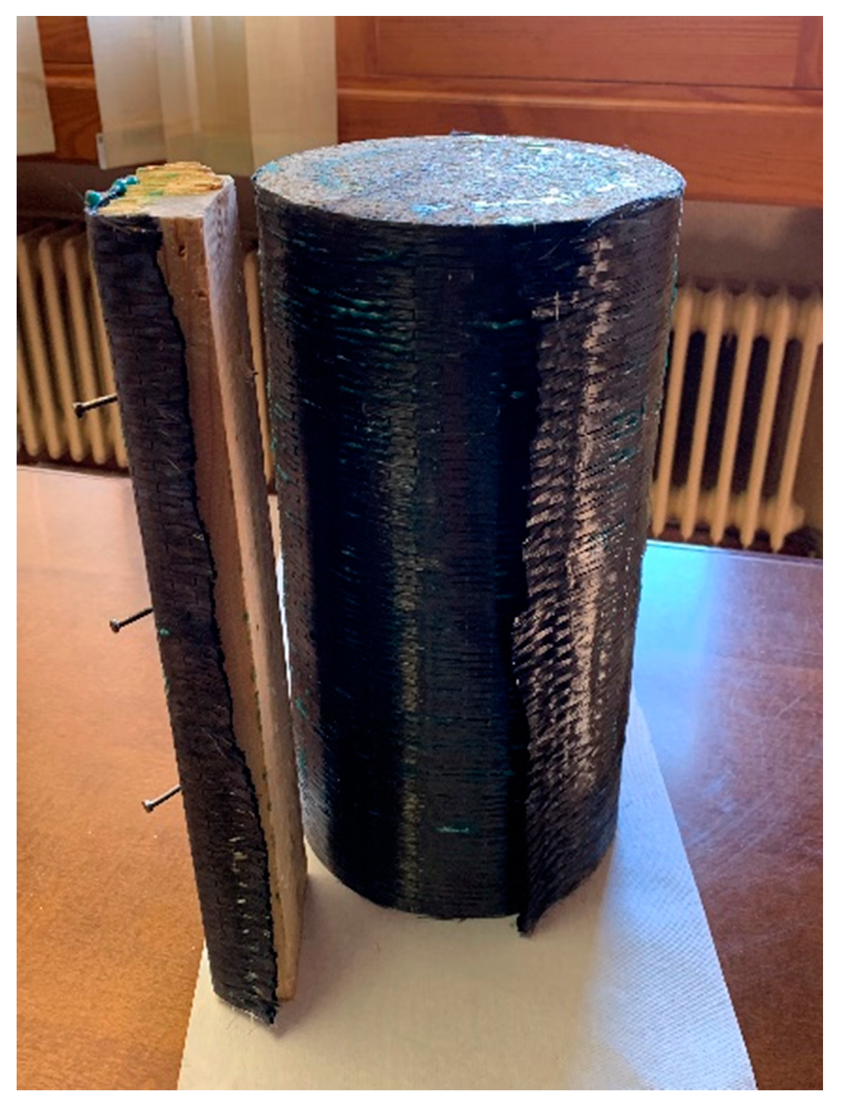
3.3.3. Active Reinforcement Process

To achieve an initial confinement tension, we set up the following “fabric application device” (Figure 3):
Where:
  • Fabric specimen to be reinforced.
  • Auxiliary elements placed on both ends of the specimen to be reinforced.
  • CF adhered to the specimen to be reinforced.
  • Auxiliary specimen (not visible in the diagram) to distribute the load applied by gravitational force into the fabric without tearing it.
  • Plugs to fix the loads.
  • Guide rails supports, on which the specimen is placed, which allows the operator to turn the assembly.
  • Weights that apply a gravitational force tension in the fabric.
The “fabric application device” has a metal support (seen in the photos below) with a height of 1000 mm to save the length of overlapping wrap and anchors. In the upper part, two pieces of wood (6) in the form of a rail are stuck together.
Two cylindrical specimens of a smaller diameter (2) were stuck on the lower and upper faces in a concentric manner to serve as the rotation axes of the assembly.
With the surface cleaned and primed, one end of the fabric was anchored to a generating line on the cylindrical specimen by means of a thin bead of epoxy resin. Then, the same operation was performed by anchoring the other end to a rigid wooden bar from which three 45 N weights hung.
Once the epoxy resin had hardened, the fabric was glued by applying a thin layer of resin to the side surface of the cylinder. The assembly was then placed on the aforementioned rail so that the carbon fiber fabric was subjected to a simple tensile stress of: σ i = 135 0.167 300   N / mm 2 = 2.64   N / mm 2 .
By rotating the assembly on the rail, it was possible to apply a perfectly uniform tension on the lateral surface of the cylinder, as can be seen in the Figure 4. When winding, including the overlap (200 mm), the assembly was anchored for 48 hours to allow the epoxy resin to harden. After, the weights were removed and the fabric was trimmed to remove the rigid wooden bar. At the same time, with a small lateral stroke, the two cylinders of the upper and lower faces were removed. At the end of this procedure, five specimens were obtained (Figure 5), and we proceeded with the test.
Applying the initial tension of 2.44 N/mm2, we have:
f L i = 2 σ i t D f L i = 0.006   N / mm 2
f L i : Initial stress of confinement; σ i : Initial transverse stress; D: Diameter.
Maximum confinement:
f L = 2 . x 1488 . x   0.167 150 = 3.31   N / mm 2

4. Results

Once the three batches of specimens were prepared, the tests were carried out to measure the modulus of elasticity and to study the behavior of the reinforced specimens in the first section, as described above. Figure 6 shows the process of preparation for the laboratory tests.
Figure 6 shows how the measures are performed in the laboratory. We measured the modulus of elasticity and Poisson’s ratio, and the average results were as follows:
Batch 1: concrete specimen without reinforcement.
E c = 33014   N / mm 2 μ = 0.160
Batch 2: concrete specimens with passive reinforcement.
E c = 33103   N / mm 2 μ = 0.161
Batch 3: concrete test tubes with active reinforcement.
E c = 35820   N / mm 2 μ = 0.168
As can be seen in Figure 7, the modulus of elasticity of Batch 3 increased significantly, and the variation between Batch 1 and Batch 2 was practically nil.
In Figure 8 the results obtained for the test can be observed:
Given these results, the following facts can be extrapolated:
Introducing a uniform initial tension of σ i =   2.64   N / mm 2 in the fabric, we introduce an initial confining tension of f L i = 0.006   N / mm 2 , stiffening the set with an increase of the initial modulus of elasticity of Δ E c = 2800   N / mm 2 or 8.48 % .
The axial tension also increases; for a deformation of ε c = 0.0007 , the increase is Δ f c = 2.5   N / mm 2 or 11.50 %.

5. Discussion

In view of these results and taking into account the compression-deformation behavior model proposed by Lam and Teng [22] a new behavior model with three sections is proposed here.
The first is a perfectly elastic section and a deformation of ε c = 0.0007 .
The second is a transitional section to link the two strands of the elasto-plastic (parabolic) type that coincides with the one proposed in the model by Lam and Teng [22]. The only difference is that the proposed model takes into account the initial modulus of elasticity ( E c i ) obtained from this experiment.
Finally, the third section coincides with the one proposed by Lam and Teng [22].
The proposed tension–deformation behavior is reflected in the following expression:
f c = { E c i · ε c 0 < ε c < 0.0007 E c i ε c ( E c i E 2 ) 2 4 f c 0 0.0007 ε c ε t f c 0 + E 2 ε c ε t < ε c ε c c
The results show that passive reinforcement does not generate any tension increase in the elastic zone except for deformations greater than: ε c = 0.0007 .

6. Conclusions

As numerous studies have proven, the use of wrapped CF is suitable to increase the resistant capacity of structural elements. The confinement of the structural element ensures a three-axial stress in the concrete by preventing transverse deformations.
The introduction of an initial stress in the reinforcement improves the mechanical behavior of reinforced pillars. The research campaign described in this paper introduced an initial tension of 3.43 N/mm2 in the reinforcing fabric. Due to this pre-load, the modulus of elasticity increased by 8%. This in turn resulted in an 11% increase in the compression supported by the pillar and in a deformation of ε = 0.0007 .
This technique of introducing a preload on the wrapping element allows a more efficient use of the reinforcement material. This should translate into a more sustainable solution in the field of structural reinforcement.
The reinforcement technique presented, as described in this paper, has been developed and tested in laboratory conditions. Consequently, it has some limitations:
  • The technique was employed with prefabricated elements which could adopt a horizontal position during the reinforcement procedure.
  • The prefabricated elements did not support any compression at the time of reinforcement.
Future research could focus on two different directions to address these issues: firstly, adapting the technique to allow for the introduction of pre-loads on already built-in pillars; secondly, investigating the effects of confinement pre-loads on pillars that are already under some level of compression.

Author Contributions

The conceptualization and methodology work that led to the development of the article was done by A.L.P. and H.M.-S., E.M.G.d.T. and V.A.-C.d.A. contributed in the data validation and formal analysis of the experimental campaign.

Funding

This research received no external funding.

Acknowledgments

The reinforcement materials needed for this research were provided by DRIZORO S.L. The testing campaign was conducted in the laboratories of the ETS Ingenier, Spain.

Conflicts of Interest

The authors declare no conflict of interest.

References

  1. Baji, H.; Reza, H.; Li, C. Probabilistic assessment of FRP-confined reinforced concrete columns. Compos. Struct. 2016, 153, 851–865. [Google Scholar] [CrossRef]
  2. Song, X.; Gu, X.; Li, Y.; Chen, T.; Zhang, W. Mechanical behavior of FRPstrengthened concrete columns subjected to concentric and eccentric compression loading. Compos. Constr. 2013, 17, 336–346. [Google Scholar] [CrossRef]
  3. Saljoughian, A.; Mostofinejad, D. Corner Strip-Batten Technique for FRP-Confinement of Square RC Columns under Eccentric Loading. Compos. Constr. 2015, 20, 04015077. [Google Scholar] [CrossRef]
  4. Rochette, P.; Labossiere, P. Axial Testing of Rectangular Column Models Confined with Composites. Compos. Constr. 2000, 4, 129–136. [Google Scholar] [CrossRef]
  5. Breveglieri, M.; Barros, J.A.O.; Dalfré, G.M.; Aprile, A. Composites: Part B A parametric study on the effectiveness of the NSM technique for the flexural strengthening of continuous RC slabs. Compos. Part B 2012, 43, 1970–1987. [Google Scholar] [CrossRef]
  6. Xiao, Y.; Wu, H. Compressive Behavior of Concrete confined by various types of FRP composites jackets. J. Reinf. Plast. Compos. 2003, 22, 1187–1201. [Google Scholar] [CrossRef]
  7. Bisby, L.; Ranger, M. Axial—Flexural interaction in circular FRP-confined reinforced concrete columns. Constr. Build. Mater. 2010, 24, 1672–1681. [Google Scholar] [CrossRef]
  8. Puhrsch, C.; Kingsbury, B.; Lecun, Y. Guide for the Design and Construction of Externally Bonded FRP Systems. Structures 2005, 2, 2–6. [Google Scholar]
  9. Ozbakkaloglu, T.; Lim, J.C.; Vincent, T. FRP-confined concrete in circular sections: Review and assessment of stress-strain models. Eng. Struct. 2013, 49, 1068–1088. [Google Scholar] [CrossRef]
  10. Lam, L.; Teng, J.G. Ultimate Condition of Fiber Reinforced Polymer-Confined Concrete. J. Compos. Constr. 2004, 8, 539–548. [Google Scholar] [CrossRef]
  11. Spoelstra, M.R.; Monti, G. FRP-Confined Concrete Model. Compos. Constr. 1999, 3, 143–150. [Google Scholar] [CrossRef]
  12. Jiang, T.; Teng, J.G. Theoretical model for slender FRP-confined circular RC columns. Constr. Build. Mater. 2012, 32, 66–76. [Google Scholar] [CrossRef] [Green Version]
  13. Wu, Y.; Wang, L. Unified strenght model for square and circular concrete columns confined by external jacket. J. Struct. Eng. ASCE 2009, 135, 253–261. [Google Scholar] [CrossRef]
  14. Jiang, T.; Teng, J.G. Analysis-oriented stress-strain models for FRP-confined concrete. Eng. Struct. 2007, 29, 2968–2986. [Google Scholar] [CrossRef]
  15. Fardis, M.N.; Khalili, H.H. FRP-encased concrete as a structural material. Concr. Res. 1982, 34, 191–202. [Google Scholar] [CrossRef]
  16. Li, G. Experimental study of FRP confined concrete cylinders. Eng. Struct. 2006, 28, 1001–1008. [Google Scholar] [CrossRef]
  17. Richart, F.; Brandtzaeg, A.; Brown, R.L. A Study of the Failure of Concrete under Combined Compressive Stresses; Bulletin No. 26; Engineering Experiment Station, University of Illinois at Urbana Champaign, College of Engineering: Champaign County, IL, USA, 1928; pp. 1–104. [Google Scholar]
  18. Parvin, A.; Wang, W. Concrete columns confined by fiber composite wraps under combined axial and cyclic lateral loads. Compos. Struct. 2002, 58, 539–549. [Google Scholar] [CrossRef]
  19. Parvin, A.; Wang, W. Behavior of FRP Jacketed Concrete Columns under Eccentric Loading. Compos. Constr. Constr. 2001, 5, 146–152. [Google Scholar] [CrossRef]
  20. Chai, Y.H.; Priestley, M.N.; Seible, F. Analytical Model for Steel-Jacketed RC Circular Bridge Columns. Struct. Eng. 1994, 120, 2358–2376. [Google Scholar] [CrossRef]
  21. Xiao, Y.; Wu, H. Compressive behavior of concrete confined by carbon fiber composite jackets. J. Mater. Civ. Eng. 2000, 12, 139–146. [Google Scholar] [CrossRef]
  22. Lam, L.; Teng, J.G. Design-oriented stress—Strain model for FRP-confined concrete. Constr. Build. Mater. 2003, 17, 471–489. [Google Scholar] [CrossRef]
  23. Teng, J.G.; Jiang, T.; Lam, L.; Luo, Y.Z. Refinement of a design-oriented stress-strain model for FRP-confined concrete. J. Compos. Constr. 2009, 13, 1–27. [Google Scholar] [CrossRef]
  24. ACI Committee 440. Guide for the Design and Construction of Externally Bonded FRP Systems for Strengthening Existing Structures; CNR—Advisory Committee on Technical Recommendations for Construction: Roma, Italy, 1996. [Google Scholar]
  25. Wu, G.; Lü, Z.T.; Wu, Z.S. Strength and ductility of concrete cylinders confined with FRP composites. Constr. Build. Mater. 2006, 20, 134–148. [Google Scholar] [CrossRef]
  26. De Lorenzis, L.; Tepfers, R. Comparative Study of Models on Confinement of Concrete Cylinders with Fiber-Reinforced Polymer Composites. J. Compos. Constr. 2003, 7, 219–237. [Google Scholar] [CrossRef]
  27. Pessiki, S.; Harries, K.; Kestner, J.; Sause, R. The axial Behavior of concrete confined with fiber reinforced Jackets. J. Compos. Constr 2013, 5, 237–245. [Google Scholar] [CrossRef]
  28. Ozbakkaloglu, T.; Oehlers, D.J. Manufacture and testing of a novel FRP tube confinement system. Eng. Struct. 2008, 30, 2448–2459. [Google Scholar] [CrossRef]
  29. Lam, L.; Teng, J.G. Stress–strain model for FRP-confined concrete under cyclic axial compression. Eng. Struct. 2009, 31, 308–321. [Google Scholar] [CrossRef]
Figure 1. Proposed stress–strain model for reinforced polymer fiber (FRP)-confined concrete (source Lam and Teng see main text for references).
Sustainability 11 03289 g001
Figure 2. Confinement tension. N: Normal compression; F: Axial tension; A: Cross section; D: Diameter.
Sustainability 11 03289 g002
Figure 3. Application device to get an initial confinement tension.
Sustainability 11 03289 g003
Figure 4. (a): Rotation of the specimen on the rail. (b): Final process of the assembly.
Sustainability 11 03289 g004
Figure 5. Final view of the specimen reinforced with initial tension.
Sustainability 11 03289 g005
Figure 6. (a): Positioning of the sensors. (b): End of the trial.
Sustainability 11 03289 g006
Figure 7. Comparison of the elasticity modules obtained for each of the analyzed test blocks.
Sustainability 11 03289 g007
Figure 8. Representation of the modulus of elasticity in the working area of the pillar.
Sustainability 11 03289 g008
Table 1. Dosing of the concrete used in the experimental phase.
MaterialDensity (kg/dm3)Dosage (dm3)Dosage (kg)
Cement2.81131370
Sand2.61214560
Gravel2.814271200
Water1.00235235
Concrete density = 2.35 kg/dm3
Ratio water/cement = 0.64

