Discussion on the Reinforcement of Reinforced Concrete Slab Structures


1
School of Urban and Environmental Science, Huaiyin Normal University, Huai’an 223300, Jiangsu, China
2
Department of Civil Engineering, Chung Hua University, Hsinchu 30012, Taiwan
3
Department of Landscape Architecture, Chung Hua University, Hsinchu 30012, Taiwan
4
Department of Architecture & Urban Planning, Chung Hua University, Hsinchu 30012, Taiwan
*
Author to whom correspondence should be addressed.
Sustainability 2019, 11(6), 1756; https://doi.org/10.3390/su11061756
Submission received: 14 January 2019
/
Revised: 18 March 2019
/
Accepted: 18 March 2019
/
Published: 22 March 2019
(This article belongs to the Special Issue Selected Papers from 2nd Eurasian Conference on Educational Innovation 2019)
Abstract
:Because of global environmental changes and the continued warming of the planet, the increase in carbon dioxide emissions has had a major impact on the environment. The development of zero-carbon buildings, the promotion of energy conservation and carbon reduction, and the concept of green environmental protection are regarded as important issues for humanity to achieve sustainable development. In Taiwan, the combination of moisture and high salt content in the environment, corrosion caused by chloride ions, and earthquakes often lead to the formation of crevices in buildings. These crevices can cause rebar oxidation and corrosion and even concrete structure damage or spalling. Conventional structural damages can be repaired with epoxy resin grout. However, such practices are incapable of removing the rusted components of the rebars inside the structures and thus subject the internal rebars to continuous oxidation in the original rust-covered environment. Components located deep within the structures would still swell as a result of continuous rebar oxidation and cause concrete breaking and spalling, making previous repair efforts ineffective. This study proposes an improved repair and retrofit technique that includes the removal of rust from oxidated rebar parts, by applying low viscosity epoxy resin to the slab base and allowing it to fully penetrate the concrete cracks and surface of the rebars inside, thus producing a protective layer and repairing the bond. Additionally, carbon-fiber reinforced plastic (CFRP) patches were adopted as repair materials and attached to the beams and slab (ceiling) surfaces. Angle steels were used at the edges and installed to connect the beams to the slab with chemical anchors. The gaps between the angle steels and the slab were filled with epoxy resin grouts. On the short side of the slab, small steel H-beams were installed 1 m apart as a means of retrofit. Because the epoxy resin expands by 8% after undergoing chemical reactions, it bonds perfectly with concrete, CFRP patches, and steel materials. Approximately 10 years have elapsed since the case-study was repaired using the proposed technique, and the retrofit effect has yielded excellent results to the present day, with no occurrence of internal swelling or spalling from rebar oxidation. The proposed retrofit technique can reduce construction costs, while ensuring effective repair and maintenance of structural safety, and extend the service life of structures.
1. Introduction
Because of the global environmental changes and the continued warming of the earth, the increase in carbon dioxide emissions has had a major impact on the environment. Energy conservation and carbon reduction have become a serious issue for human beings [1]. The durability of reinforced concrete (RC) is one of the most concerning issues for infrastructure around the world [2]. Sustainable development covers a wide range. When buildings are damaged by various factors, the use of repair and reinforcement structures to extend the use of buildings can avoid the dilemma of building demolition and reconstruction. Zero-carbon buildings, that is, buildings whose annual net energy consumption or carbon emissions are zero, and zero-carbon buildings are regarded as an important mainstream for sustainable development in the future. [3]. The concept of a “zero carbon building” is to minimize the energy consumption of the building. At the same time, the building can also produce renewable energy by itself during the operation to offset the carbon emissions generated by the energy consumption during operation. In order to achieve a zero-energy building design, we must first improve the energy efficiency of the building, followed by a large reduction in energy demand and the use of renewable energy as much as possible. Generalized zero-energy buildings should be included in the evaluation calculations, such as planning and design, building material production, material transportation, construction, daily use, renovation, and disposal [4]. The construction industry is growing intensively, especially in the field of large area floors [5]. This increase is mainly due to the growth of the production and transport industries and the fact that larger areas are being adapted for storage. To ensure a suitable floor for more significant loads, epoxy resins are mainly used as concrete surface coatings [6,7]. The current use of Epoxy Resin materials has been widely discussed in extending the life of older buildings. This paper explores the possible cracking problems during the use and maintenance of buildings. This study also proposes a set of repair and reinforcement methods, and discusses the results of the application.
1.1. Research Background and Motivation
In various stages of their life cycle, including construction material production and transportation, construction, maintenance, renovation, demolition, waste disposal, recycling, and reuse, buildings can severely impact the environment. Although the introduction of green architectural concepts has slightly mitigated the influence of construction projects, our environment is still subject to various damages causing by excessive manual development as well as threats of ecological catastrophe and extreme climate change. The question of how to extend the service life of buildings to enhance their benefits and reduce the effects of building construction on the environment has become a key topic for ensuring sustainable development.
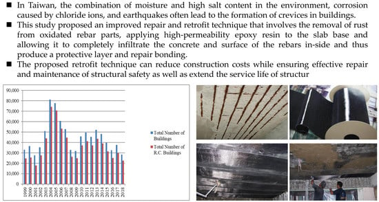
Statistics on issued building licenses from Taiwan’s Directorate General of Budget, Accounting and Statistics, Executive Yuan revealed that from January 1999 to August 2018, the total number of buildings in Taiwan reached 898,492, of which 739,045 were constructed with RC, accounting for approximately 82.25% of all structures [8] (Figure 1). According to the “Table of Durable Years of Building Improvement and Annual Depreciation Rates in Taipei City for the Purpose of Land Price Survey” [9], the RC buildings have a durable life of 60 years. In a research report, Lee mentioned that if condominium buildings can satisfactory implement their management and maintenance plans in terms of structure, then extending their service life as residences to 100 years is achievable [10]. To extend building service life, the seismic capacity of the buildings and the durability of structural materials have become crucial. The government implemented the Urban Renewal Industry Action Plan in 2011 [11], offering subsidies to buildings aged 20–29 years for maintenance and renovation. In this action plan, buildings aged 20 years or older are regarded as old buildings that require regular maintenance as well as structural monitoring and evaluation.
The Jiji earthquake occurred in Taiwan on 21 September 1999, causing numerous buildings to be rated as dangerous or potentially dangerous [12]. The results indicated that a multitude of undamaged buildings could still have problems in terms of seismic capacity. Because the demolition and reconstruction of damaged buildings requires substantial funds, structural strengthening is an essential mean of enhancing the seismic capacity of buildings. In 1994, the Fulin Community in Shilin, Taipei was revealed to be the first case of houses constructed with unwashed sea sand in Taiwan. Sea sand, or sand containing salt, was mixed into the ready-mix concrete that was used as a construction material. High-concentration chloride ions corroded the reinforcement bars (rebars) and caused them to rust. The corrosion volume expanded 7–9 times, causing the spalling of large areas of RC blocks from the structures, severely damaging the usability and safety of the buildings. To lower the reconstruction cost and extend the service life of structures, the application of a safe and effective structural strengthening system is paramount.
1.2. Objectives
This study investigated the mechanisms of structural failure in RC slabs (ceilings) through literature review and case-study verification. We identified contemporary constructional methods for RC slab structural strengthening and their drawbacks, analyzed domestic cases that had applied these methods, investigated the characteristics and structural behaviors of materials used in these methods, and designed a stable and feasible method. The proposed method was then verified with actual cases. The results can serve as a reference for relevant scholars, government officials, and industrial personnel when applying constructional methods for RC slab structural strengthening.
2. Literature Review
Tang et al. [13] reviewed recent research activities on the durability of concrete and recommended developing a new approach for accurately estimating the durability service life of RC structures. Reinforcement corrosion is regarded as a crucial factor in causing the deterioration of RC structures [14]. There are many reasons for the corrosion of RC structures, including the physical aging, chemical erosion, climatic conditions, earthquakes and other effects. The following is a description for RC buildings on materials and structural behavior, cracking, and oxidation phenomena.
2.1. RC Materials and Structural Behaviors
Zhang et al. [15] presented the test results of two corroded RC beams subjected to 14 years and 23 years of chloride exposure, and proposed a relationship between area loss of reinforcements and the crack width of beams. RC is composed of rebars and concrete, in which concrete exhibits high compressive strength and rebars have tensile strength. Because these two materials have similar coefficients of thermal expansion, they do not separate from each other as a result of temperature changes. Furthermore, both materials can be easily obtained, and RC can be molded into random shapes and sizes by using formwork. Therefore, RC has been widely applied in building structures. The anchorage of RC is generated by four types of rebar–concrete bonding [16]:
- Creating a chemical adhesive force, or cementing force, on the interface between rebars and concrete,
- Producing friction by causing concrete to shrink and grasp rebars tightly,
- Increasing the grip between rebars and concrete by making raised bamboo joints on the surface of rebars,
- Generating anchorage by attaching hooks or bends to the tops of rebars or adding short rebars or angle bars to the anchorage area through welding.
2.2. Concrete Cracking
During concrete pouring, to ensure that the concrete can be placed in the story under construction and evenly fill the structure, construction teams typically increase the proportion of water in the water–cement ratio and add an amount of water that far exceeds that required for cement hydration. Such a practice is implemented for the convenience of working, which includes other tasks such as controlling the distance between the rebars and the formworks, maintaining the maximum particle size of a coarse aggregate at a designated level, and applying suitable vibrations. The excess amount of water flows from formwork joints during concrete pouring and tamping; excess water may also gradually rise to the surface of the newly poured concrete. During concrete hydration, the volume of concrete shrinks as a result of water evaporation or loss, thereby producing visible or nonvisible cracks.
In general, cracking in RC structures is a result of exerted stress, which can be divided into internal and external stress.
- Internal stress is caused by shrinkage from hardening or drying, temperature and humidity changes, or chemical changes in the concrete. As the internal structure shrinks as a result, the binding effect of the structure prevents the alleviation of internal stress, leading to crack formation.
- External stress primarily manifests as fatigue caused by pressure, tension, shear force, bending moment, torsion, and vibration. These external forces produce corresponding resistant stresses when exerted on structures. Cracks emerge when the internal resistant stress is weaker than the external force.
2.3. Rebar Oxidation
In the RC structure, if the floor tiles are applied by cement mortar, the bonding layer is not high in strength and poor in water tightness. Moreover, floor tiles are vitreous and feature water impermeability, impeding moisture evaporation and causing the floor to remain humid in the long-term. Furthermore, because the floor is subject to tensile force, it tends to crack and moisture and air can easily permeate the structure through the crevices, causing rebar oxidation at locations where the protection layer is insufficient, further leading to concrete spalling (Figure 2).
2.4. Determination of Damage Level for RC Structures
The damage level of RC structures is detailed in Table 1 based on the Technical Manual of the Maintenance and Strengthening of Existing Concrete Structures compiled by the Chinese Institute of Civil and Hydraulic Engineering.
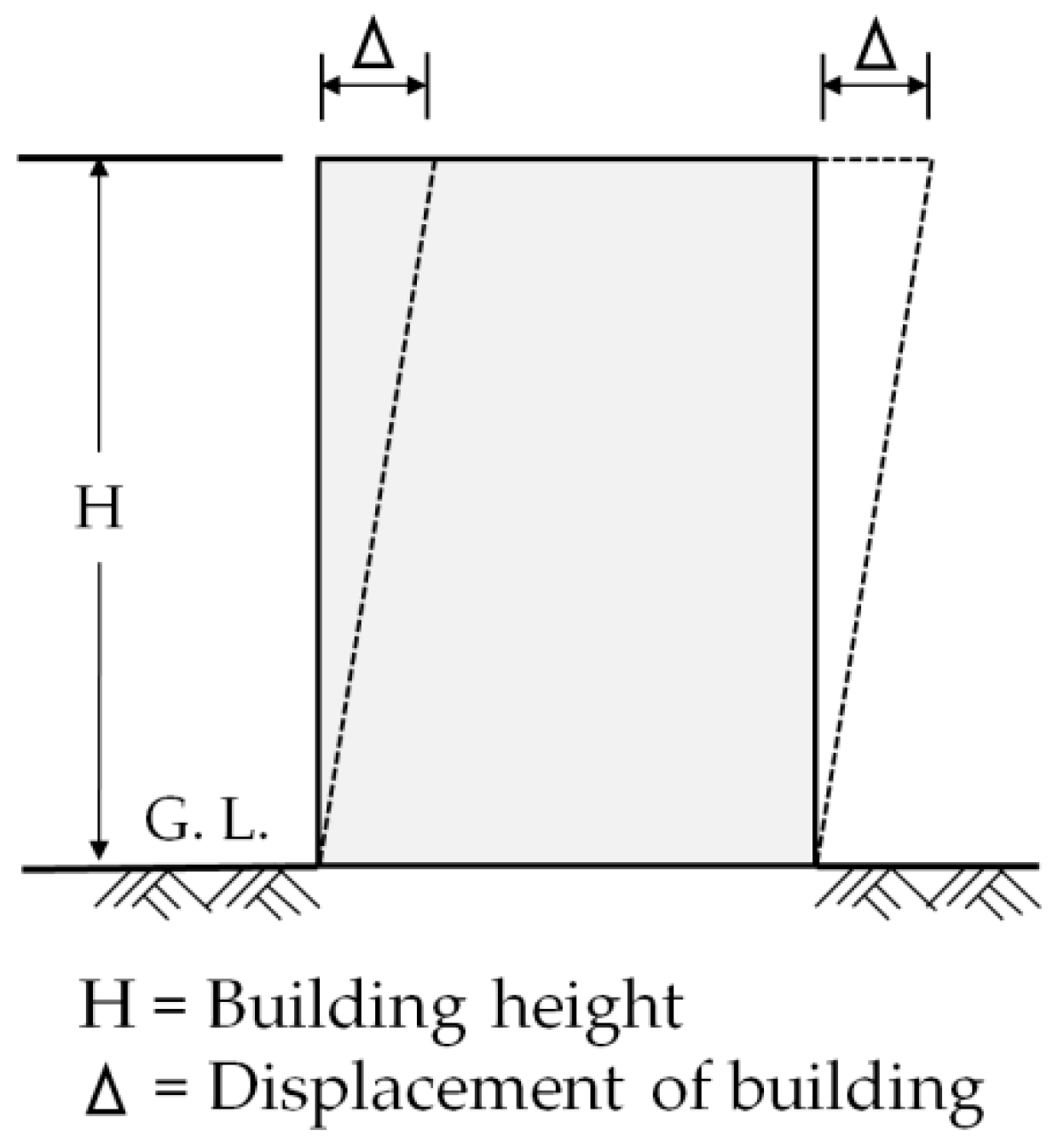
Typically, after earthquakes, some buildings tilt (Figure 3). The process of assessing subsequent damage and the corresponding structural repair and retrofit is illustrated in Figure 4, which contains four types of responsive measures.
- House tilt 394/H > 1/50: Demolition and reconstruction are required, regardless of the damage level.
- House tilt 1/100 ≤ △/H < 1/50: Although the damage to the main structure has not threatened safety, a structural seismic resistance assessment must be conducted. The assessment project includes structural systems, structural details, structural status, and quantitative analysis. After the safety is confirmed by the structural seismic resistance assessment, the repair and reinforcement assessment are performed.
- House tilt 1/200 ≤ △/H < 1/100: There are no safety concerns in the house, and the repair plan can be planned according to the damage situation. Performing a retrofit plan based on current damage state of the structure and functional requirements of the building (such as an increase in the load caused by changing the function of the house).
- House tilt △/H < 1/200: The houses are safe. Local repair can be performed depending on the conditions of the houses; no retrofit is required.
3. Repair and Retrofit of RC Structures
3.1. Differences between Repair and Retrofit
In brief, repair refers to the restoration of buildings to their original condition before sustaining damage to reestablish their original strength and prevent deterioration. Conversely, retrofit not only involves restoring buildings to their original conditions but also includes strengthening or enhancing the structural strength, safety, or endurance of the building. In practice, repair primarily focuses on repairing structural components, whereas retrofit can either reinforce structural components or the overall structural system [18].
3.2. Types of Retrofit
In the present paper, different external surface treatments published in the literature as preventive solutions for improving the performance of existing concrete constructions are presented and discussed. They are categorized as repair materials for concrete conservation, protection surface methods against moisture and aggressive agent penetration, injection techniques for crack sealing, and preventive repair solutions with smart functionalities [19]. Applications have been reported as an overlay suitable for energy absorption in structural shear walls for the seismic retrofit of R/C buildings [20] as well as in masonry buildings, increasing their earthquake resistance [21]. Furthermore, patch repair can effectively suppress chloride penetration and prevent reinforcement corrosion [22,23,24]. The seismic capacity of current RC buildings is primarily determined by member strength and toughness, the shape of the structural system, and the time index. However, the shape is constrained by the building design applied in the original construction, and the time index reflects the amount of time that has elapsed since the structure was created; neither factor can be easily changed. Therefore, regarding retrofit, endeavoring to enhance the strength and toughness of members is the most practical method. Increasing strength or toughness can be further divided into the following four types.
- Strength resistance-type retrofit: This method focuses on enhancing the strength of a building. This type typically involves such retrofitting efforts as thickening existing shear walls, filling wall crevices, or adding shear walls or steel braces. However, although this technique can considerably enhance the stiffness of buildings, the toughness is relatively poor.
- Endurance resistance-type retrofit: This method focuses on enhancing the nonelastic deformation capacity (toughness) of the building. This method typically involves such retrofitting efforts as enhancing the shear resistance of RC columns, ensuring the flexural endurance of RC beams or increasing the toughness of the steel beam-column joints.
- Strength and toughness resistance-type retrofit: This method focuses on simultaneously enhancing the building’s strength and toughness. This method typically involves such retrofitting efforts as adding seismic-resistant walls or braces or decreasing the centers of stiffness and mass to achieve balance in structural deployment.
- RC beam shear reinforcement-type retrofit: This reinforcement is provided with steel plates on the side and bottom of the beam and is fixed to the RC beam by chemical anchor bolts to improve the shear resistance of the RC beam.
3.3. Retrofitting Techniques of RC Structures
In the “Investigation on the Feasibility of the Technical Manual of Emergency RC Building Repair and Retrofit after the 921 Earthquake,” Lin proposed several techniques for the repair and retrofit of structural components [25]:
- Grouting epoxy resin into crevices: Applying pressure grouting to structural crevices with a width of ≥0.3 mm that are located in the RC beams, columns, slabs, or walls until the crevices are completely filled. This technique can repair damaged structural components and prevent rebar rusting caused by moisture infiltration.
- First eliminating loose concrete parts and then repairing with an epoxy resin grout: The Italian National Research Council [26] has highlighted the importance of a quality control that includes the determination of concrete conditions, removal of any deteriorated or loose concrete, cleaning and protection from corrosion of existing steel reinforcement, and finally, substrate preparation for receiving the selected FRP reinforcement. In accordance with this standard, once the quality control of the substrate has been performed, the deteriorated concrete has been removed, the concrete cross section has been restored, and the existing steel reinforcement has been properly treated, sandblasting of the concrete surface can be performed. In this guidance, it is pointed out that FRP or epoxy resin materials can obtain more effective seismic resistance. If severe cracking or loosening has been identified in local parts of an RC structural component, or if the entire component clearly exhibits no seismic capacity, then the repair team can remove the severely cracked or loosened parts. This process is done before repairing and retrofitting the structural component with an epoxy resin grout.
- Partial removing and rebuilding of a component: When the RC members are severely cracked, or the proportion of loose parts is too large to be filled with epoxy resin mortar, the components are partially knocked out and rebuilt.
- Cathodic protection technique: When rebar corrosion occurs in RC structures as a result of excessive chloride ion content (e.g., houses constructed with unwashed sea sand), the cathodic protection technique can be adopted to inhibit rebar corrosion.
3.4. Conventional Practices of RC Structure Repair and Retrofit
Numerous methods of RC structure repair and retrofit have been adopted, including the following:
- Knocking out burst parts caused by rebar corrosion,
- Removing rust from rebars,
- Coating rusted rebars with antirust paint,
- Filling the spalling area with epoxy clay, and
- Wrapping the burst parts with carbon-fiber reinforced plastic (CFRP) patches.
Although these methods can temporarily inhibit corrosion in the exposed parts of rebars, those in the concrete have been dampened and rusted. Despite the fact that exposed parts have undergone rust removal and are coated with a protection layer of antirust paint, the rusted rebars inside the concrete would eventually swell, causing the concrete in the structure to crack or even spall. Consequently, such efforts to repair the concrete structure and the repaired layer have been proven ineffective.
3.5. Materials and Techniques of the RC Slab Retrofit Proposed in This Study
This study has proposed a technique for RC structure repair and retrofit, and the materials comprise CFRP patches, substrates, interface materials applied between the patches and substrates, and rigid materials for retrofit, which are detailed as follows.
- CFRP patches: Externally bonded reinforcement (EBR) appeared in the 1980s [27]. In the last decades, fiber reinforced polymer (FRP) materials have been increasingly proposed to strengthen RC structures [28]. Significant investigation has been carried out in order to predict the bond strength of EBR systems with CFRP materials in concrete and, as a consequence of those studies, many analytical expressions can be found in the literature, including in standards [29]. Different strengthening techniques have been developed for applying FRP. Based on the above research, it is found that the reinforcement application has been proven to have a good effect on increasing the bearing capacity of the concrete plate, where the FRP laminate is glued onto the tensile face of the RC element [29]. A CFRP composite was obtained by extracting black organic materials from acrylic resin, petroleum, and coal, transforming these organic materials into fibers, and subjecting them to a special heat treatment. Table 2 presents the physical properties of the CFRP patches used in this study (displayed in Figure 5).
- Chemical anchor: Chemical anchors consist of a screw, chemical hose, washer, and nut; the chemical hose (or chemical agent tube packaged with plastics) contains a reactive resin, a curing agent, and quartz particles. Chemical bolts are used to facilitate the adherence of the angle steel, H-beam, beam side, and beam bottom steel plates to the concrete, thereby providing bonding and mechanical-occlusion forces to resist tensile strength and shear force.
- H-beam: The H-beams used in this study possess the features of a lightweight structure, favorable plasticity and toughness, and high structural stability and strength; therefore, H-beams are particularly appropriate for use in the structural retrofit of buildings in earthquake-prone areas. The H-beam is fixed on the reinforced concrete beam by chemical anchor bolts or welded to the reinforced steel beam, and the material characteristics of the steel are used to form the support beam, which can effectively improve the seismic resistance of the structure.
- Epoxy resin primer: The epoxy resin primer adopted was prepared at a mixing proportion of 2 (main agent): 1 (hardener) by weight. The viscosity was 1200–1600 cps, which is extremely suitable for capillary penetration. Its specific weight after mixing was 1.15, and the hardening time required was 4–6 h. The strength values of this epoxy resin primer are as follows:
- (1)
- Compressive strength (CNS 10142-2-11, ASTM D695, 25 °C—7 days) 700–800 kg/cm2
- (2)
- Bending strength (CNS 10142-2-10, ASTM D790, 25 °C—7 days) 500–600 kg/cm2
- (3)
- Tensile strength (CNS 2335-3-2, ASTM D638, 25 °C—7 days) 460 kg/cm2
- (4)
- Strength of the adhesive between the primer and concrete: (ASTM D1002, 25 °C—7 days) 100 kg/cm2
This primer grout exhibited no shrinkage after infiltration and hardening. It could completely coat rebars and thus prevent them from oxidation and the subsequent rusting caused by ambient moisture. Therefore, this primer produces a good consolidation of deteriorated concrete for RC structures. The compressive strength of the primer is extremely high, reaching 10,000 PSI or higher 7 years after application. Repair teams often disregard the value of work during this stage, and merely remove the deteriorated or spalled concrete parts. However, these repair teams were unware of hidden crevices inside the structures and only coated the rebars with a surface medium, which would eventually cause structural damage from continual rebar rusting and necessitate further repair. - Lightweight epoxy resin grout: The lightweight epoxy resin grout used in this study was prepared by aggregating and polymerizing lightweight hollow ceramic sand (lightweight sand) and lightweight powder with epoxy resin. This grout features light specific weight, favorable workability and durability, excellent strength, and simple application.
- Angle steel: Angle steels were adopted to affix both ends of the CFRP material.
Other materials used in this study include epoxy resin (physical properties listed on Table 3), Type I Portland cement, and nonshrinkage cement.
4. Planning and Implementation Steps of RC Slab Repair and Retrofit and Case-Study Description
4.1. Planning and Implementation Steps of RC Slab Repair and Retrofit
Repair and retrofit efforts were executed on damaged RC structures. The planning and design steps were as follows:
- Surveying relevant information regarding existing RC buildings and structures:The research team surveyed the types and usage conditions of existing structures and documented the current conditions of buildings and structures using photographs and descriptions.
- Surveying the causes of structural damages sustained by existing buildings:The research team surveyed the causes of structural damages to determine whether they were related to inappropriate design changes or usage. Measurements, as well as structural safety and seismic assessments, were also performed to determine whether the structural damages were caused by natural deterioration, artificial errors, or natural disasters. Additionally, the team determined whether the structures would be usable after retrofit.
- Developing the repair and retrofit plan:The retrofit plan must satisfy the structure performance and safety requirements while remaining cost-effective. The repair and retrofit plan must be reviewed and approved by a government-certified technician, architect or engineering consultant before the repair and retrofit project can be carried out.
- Designing techniques used in the repair and retrofit efforts:The retrofit techniques used in this study consisted of coating the slab with CFRP materials, bracing the slab with H-beams, performing a vertical steel-plate retrofit to beams, installing chemical anchors for fixation, and filling the gaps between the steel plates and the beams with epoxy resin grout for adhesion.
- Conducting a postretrofit structural assessment:The postretrofit structural safety of buildings subjected to the retrofit must be conducted from the perspective of overall safety, such as through a structural seismic assessment. Experts and scholars may also be invited to review the RC structures after structural repair and retrofit.
- Implementing postretrofit structural maintenance and management:Routine assessments and surveillance investigations should be conducted on postretrofit structures every 2–3 years. Upon detection of a structural abnormality, the investigation results must be documented and photographed for maintenance and management purposes.
4.2. Construction Cases of RC Slab Repair and Retrofit
The research team has engaged in the RC slab repair and retrofit of numerous cases, including dozens of cases of condominium buildings in Linkou and townhouses in Neihu, Taipei. The case examined in this study was approximately 20 years old at the time of repair and retrofit; at this time, its RC ceiling had spalled severely and its rebars were severely corroded. The repair and retrofit process of this case was as follows:
- The research team removed furniture in the house to prevent it from becoming dirty or damaged during construction. Sheets were paved on the floor for protection.
- The research team removed all loose and spalled parts of the concrete, used a grinder and other descaling tools to remove corroded parts on the rebar surface, and removed the entire stucco layer on the cement grout (Figure 6).
- The research team removed the stucco layer on the cement grout on the bottom and sides of the RC beams, performed a steel-plate retrofit where necessary, fastened steel plates to the beams with chemical anchors, and filled the gap between the steel plates and beams with an epoxy resin grout.
- Applying a rust-conversion agent to the rebars exposed from the slab for derusting and using antirust paint to protect the rebars from further corrosion.
- Applying a low viscosity epoxy resin to the slab base to enable it to completely infiltrate the structures (Figure 7).
- Where crevices were present in the slab, low-pressure grouting was employed when pouring the epoxy resin to ensure that all crevices were completely filled.
- Flattening extruding parts with a grinder and smoothing the entire area of the slab by evenly applying the lightweight epoxy resin grout or nonshrinkage cement (Figure 8).
- Placing H-beams (150 mm × 150 mm) perpendicular to the CFRP patches and welding the H-beams (small beams) onto the steel beams to brace the entire ceiling. Filling gaps between the H-beams and slab with nonshrinkage cement or epoxy resin grout (Figure 11). Epoxy resin expands when hardened; this property enabled CFRP patches to more closely adhere to the slab. In combination with the newly added H-beams, a satisfactory retrofitting effect could be achieved.
- If the slab to be retrofitted had undergone severe spalling, then H-beams could be installed first to brace the ceiling and prevent ceiling collapse. CFRP patches could be attached later by passing over the H-beams.
5. Results
Approximately 10 years elapsed since the repair and retrofit of the cases discussed in this study. All buildings that applied this repair and retrofit technique remained structurally intact; no spalling, swelling, or cracking has been detected (Figure 12). This proves that the proposed technique can solve the problems associated with conventional repair and retrofit techniques, in particular the inability to prevent continual oxidation of rebars within the structures.
Research on structural repair and retrofit has advanced technology, and future studies can focus on the observation of the structural changes in more detail and applying a load test on the slab. Non-destructive (ND) evaluation by thermographic analysis was applied to the RC beams strengthened with CFRP laminates, to assess the quality of the interface between reinforcement and substrate before and under loading during laboratory bending tests [30]. ND can be used to detect the invisible damage of the peeling or expansion after the RC slab is reinforced.
The repair and retrofit of the RC structures includes removing loose concrete, derusting the structural steel bars, and coating with rust ion conversion agents. The most effective improvement project is to inject low viscosity epoxy resin into the RC crack, which can effectively penetrate the structure; the repair effect is very good for the honeycomb of the original RC structure, the compaction of concealed, hidden cracks and the weathering of the structure. Epoxy resin can fill the pores between concrete and steel bars and completely cover the steel bars, so that the steel bars are isolated from air and moisture, which can prevent steel corrosion from recurring. The aggregate in the concrete is bonded to the epoxy resin to produce a compact and high-strength structure.
The carbon fiber material is adhered to the RC slab surface of the coated epoxy resin, and the carbon fiber material has a high tensile strength property, which can effectively improve the tensile strength of the RC slab. The reinforcement of the steel plates on both sides and the bottom of the RC beam, and the addition of the H beam at the bottom of the RC slab, can enhance the RC structure to the proposed reinforcement. At present, the structural seismic strengthening technology has developed to a fairly mature stage. Although there is still research and development space in academic or engineering practice, it is difficult to undertake long-term monitoring after the RC slab is reinforced. Therefore, this analysis can only be used as a material property assumption and a review of the appearance after the completion of the reinforcement.
The RC slab repair and retrofit method discussed in this study can provide extremely effective repair functions for structural damage caused by design, materials, construction, environment, external force, etc., throughout the life cycle of old buildings. The bearing strength of the RC structure can be increased as needed, and the service life of the RC structure can be extended. It is possible to dispense with the need for old buildings to be demolished and rebuilt. This technique presents a great contribution and significance to sustainable development and environmental protection.
6. Discussion
Early conventional RC repair and retrofit techniques focused solely on removing spalled concrete parts, applying antirust agents to corroded rebars, and filling and flattening the surface with grout. These techniques are unable to protect the corroded rebars inside the concrete; therefore, after repair and retrofit, the rebars inside the structures continued to be subjected to oxidation and corrosion. When the rebars began to rust and swell, they were still able to cause spalling by breaking through the structures and the repair surface; consequently, such repair efforts were rendered ineffective. The proposed repair and retrofit technique involved the use of low viscosity epoxy resin to coat the entire area of the slab base. This process ensured that the resin completely infiltrated the structures to produce consolidation between the rebars and the internally cracked concrete parts and achieved consolidation. Such a practice inhibits moisture infiltration, prevents rebars from continual oxidation and rusting, and repairs hidden crevices within structural slabs, thereby solving the problems associated with conventional practices of RC structure repair and retrofit. Furthermore, the proposed technique involves attaching CFRP patches to the slab base, using angle steels to affix the patch ends, and installing small H-beams for reinforcement. The lightweight epoxy resin grout filled the gaps between the structures and the H-beams and angle steels. Furthermore, the lightweight epoxy resin grout or the nonshrinkage cement painted as the stucco layer expanded by approximately 8% after drying, thus forming a strong and effective protection mechanism.
In order to allow human beings to avoid destroying the ecological environment as much as possible, future research suggests that the government, academia, and industry should bring together experiences and share industry cases, to integrate analyses by means of non-destructive testing, establish an evaluation survey mode, and set standard specifications. The repair and retrofit mode changes year by year, the monitoring data is continuously corrected, and the requirements, methods and techniques are ratified, to establish a more effective repair and retrofit method, so that structures can extend their service lives to effectively achieve a sustainable ideal.
Author Contributions
This paper was written based on Master Thesis of C.-C.L. Study process of the paper was conducted mainly by W.-L.H. and Y.-C.S. W.-L.H. has adjusted the format of the paper to fit the style of Sustainability. He has reinforced the references to meet the reviewer‘s requirements. Y.-C.S. has prepared the explanation to reviewers in Response Letter. C.-C.L. has confirmed some construction details. W.-C.L. has provided the related repair and retrofit information for reinforce concrete structures.
Funding
This research received no external funding.
Conflicts of Interest
The author declares no conflicts of interest.
References
- Chang, Y.-S. Life Cycle Assessment on the Reduction of Carbon Dioxide Emission of Buildings; Chenggong University: Tainan, Taiwan, 2002. (In Chinese) [Google Scholar]
- Shen, J.; Gao, X.; Li, B.; Du, K.; Jin, R.; Chen, W.; Xu, Y. Damage evolution of rc beams under simultaneous reinforcement corrosion and sustained load. Materials 2019, 12, 627. [Google Scholar] [CrossRef] [PubMed]
- Ng, T.S.; Yau, R.M.; Lam, T.N.; Cheng, V.S. Design and commission a zero-carbon building for hot and humid climate. Int. J. Low-Carbon Technol. 2016, 11, 222–234. [Google Scholar] [CrossRef]
- Cheng, Z.-L. Practice of zero carbon building. Tauwan Archit. 2017, 531. Available online: http://www.twarchitect.org.tw/special/%E9%9B%B6%E7%A2%B3%E5%BB%BA%E7%AF%89%E7%9A%84%E5%AF%A6%E8%B8%90/ (accessed on 30 October 2018). (In Chinese).
- Krzywiński, K.; Sadowski, Ł. The effect of texturing of the surface of concrete substrate on the pull-off strength of epoxy resin coating. Coatings 2019, 9, 143. [Google Scholar] [CrossRef]
- Gruszczyński, M. The use of thin cement-polymer layers to repair and strengthening concrete floors. Mater. Bud. 2018, 9, 30–33. [Google Scholar]
- Sadowski, Ł. Adhesion in Layered Cement Composites; Springer International Publishing: Cham, Switzerland, 2019. [Google Scholar]
- Directorate General of Budget, A.a.S., Executive Yuan, Statistics on Issued Building Licenses from 1999–2018. Available online: http://statdb.dgbas.gov.tw/pxweb/Dialog/varval.asp?ma=HC0102A1M&ti=%AE%D6%B5o%AB%D8%BFv%AA%AB%AB%D8%B3y%B0%F5%B7%D3-%AB%F6%BAc%B3y%A7O%A4%C0-%A4%EB&path=../PXfile/Construction/&lang=9&strList=L (accessed on 30 October 2018).
- Taipei City Government. Table of the Service Life and Annual Depreciation Rates of Building Improvements in Taipei City for the Purpose of Land Price Survey. Available online: http://www.land.gov.taipei/ct.asp?xItem=12519&CtNode=56902&mp=111001 (accessed on 28 September 2015).
- Lee, Y.S. Discussion with the Valuation Factors of Right Value when the Old-Mansion Is Reconstructed; Architecture and Building Research Institute, Ministry of the Interior: New Taipei City, Taiwan, 2005.
- Ministry of the Interior Executive Yuan. Urban Renewal Industry Action Plan; Ministry of the Interior Executive Yuan: Taipei, Taiwan, 2010.
- Ministry of the Interior. Rating System of the Hazard Level of Buildings Underwent an Earthquake and Evaluation Standards for Their Usage; Ministry of the Interior: Taipei, Taiwan, 1996.
- Tang, S.W.; Yao, Y.; Andrade, C.; Li, Z. Recent durability studies on concrete structure. Cem. Concr. Res. 2015, 78, 143–154. [Google Scholar] [CrossRef]
- Zhao, Y.; Jin, W. Steel Corrosion-Induced Concrete Cracking; Butterworth-Heinemann: Oxford, UK, 2016. [Google Scholar]
- Zhang, R.; Castel, A.; François, R. Concrete cover cracking with reinforcement corrosion of rc beam during chloride-induced corrosion process. Cem. Concr. Res. 2010, 40, 415–425. [Google Scholar] [CrossRef]
- Chen, C.H. Fundamental Research on Applying Rebar Implanting to Strengthen Concrete Structures; National Central University: Taoyuan City, Taiwan, 2001. [Google Scholar]
- Chinese Institute of Civil and Hydraulic Engineering. Strengthening of Existing Concrete Structures (Civil Engineering 405-94); Chinese Institute of Civil and Hydraulic Engineering: Taipei, Taiwan, 2005. [Google Scholar]
- Hsueh, C.-H. Retrofit of Rectangle rc Beams by Using Cfrp Wrapping and Chemical Anchors; National Taipei University of Technology: Taipei, Taiwan, 2009. [Google Scholar]
- Sánchez, M.; Faria, P.; Ferrara, L.; Horszczaruk, E.; Jonkers, H.M.; Kwiecień, A.; Mosa, J.; Peled, A.; Pereira, A.S.; Snoeck, D.; et al. External treatments for the preventive repair of existing constructions: A review. Constr. Build. Mater. 2018, 193, 435–452. [Google Scholar] [CrossRef]
- Li, V.C.; Horii, H.; Kabele, P.; Kanda, T.; Lim, Y.M. Repair and retrofit with engineered cementitious composites. Eng. Fract. Mech. 2000, 65, 317–334. [Google Scholar] [CrossRef]
- Mechtcherine, V.; Bruedern, A.; Urbonas, T. Strengthening/retrofitting of masonry by using thin layers of sprayed strain-hardening cement-based composites (sshcc). In Proceedings of the 4th International Conference on Concrete Repair, Dresden, Germany, 26–28 September 2011; pp. 451–460. [Google Scholar]
- Kobayashi, K.; Iizuka, T.; Kurachi, H.; Rokugo, K. Corrosion protection performance of high performance fiber reinforced cement composites as a repair material. Cem. Concr. Compos. 2010, 32, 411–420. [Google Scholar] [CrossRef]
- Kunieda, M.; Rokugo, K. Recent progress on hpfrcc in japan required performance and applications. J. Adv. Concr. Technol. 2006, 4, 19–33. [Google Scholar] [CrossRef]
- Rokugo, K.; Kanda, T.; Yokota, H.; Sakata, N. Applications and recommendations of high performance fiber reinforced cement composites with multiple fine cracking (hpfrcc) in japan. Mater. Struct. 2009, 42, 1197. [Google Scholar] [CrossRef]
- Lin, R.C. Feasibility study on the manual of emergency repair and reinforcement of damaged reinforced concrete buildings after the 921 earthquake. Mod. Constr. 2000, 245, 37–46. [Google Scholar]
- Council, N.R. Guide for the Design and Construction of Externally Bonded frp Systems for Strengthening Existing Structures; Advisory Committee on Technical Recommendations for Construction: Rome, Italy, 2013; Volume CNR-DT 200R1. [Google Scholar]
- Czaderski, C.; Meier, U. Ebr strengthening technique for concrete, long-term behaviour and historical survey. Polymers 2018, 10, 77. [Google Scholar] [CrossRef]
- Bank, L.C. Composites for Construction: Structural Design with frp Materials; John Wiley & Sons: Hoboken, NJ, USA, 2006. [Google Scholar]
- Soares, S.; Sena-Cruz, J.; Cruz, J.R.; Fernandes, P. Influence of surface preparation method on the bond behavior of externally bonded cfrp reinforcements in concrete. Materials 2019, 12, 414. [Google Scholar] [CrossRef] [PubMed]
- Valluzzi, M.; Grinzato, E.; Pellegrino, C.; Modena, C. Ir thermography for interface analysis of frp laminates externally bonded to rc beams. Mater. Struct. 2009, 42, 25–34. [Google Scholar] [CrossRef]
Figure 1.
Total number of newly constructed buildings and reinforced concrete (RC) buildings from 1999 to 2018.
Figure 1.
Total number of newly constructed buildings and reinforced concrete (RC) buildings from 1999 to 2018.
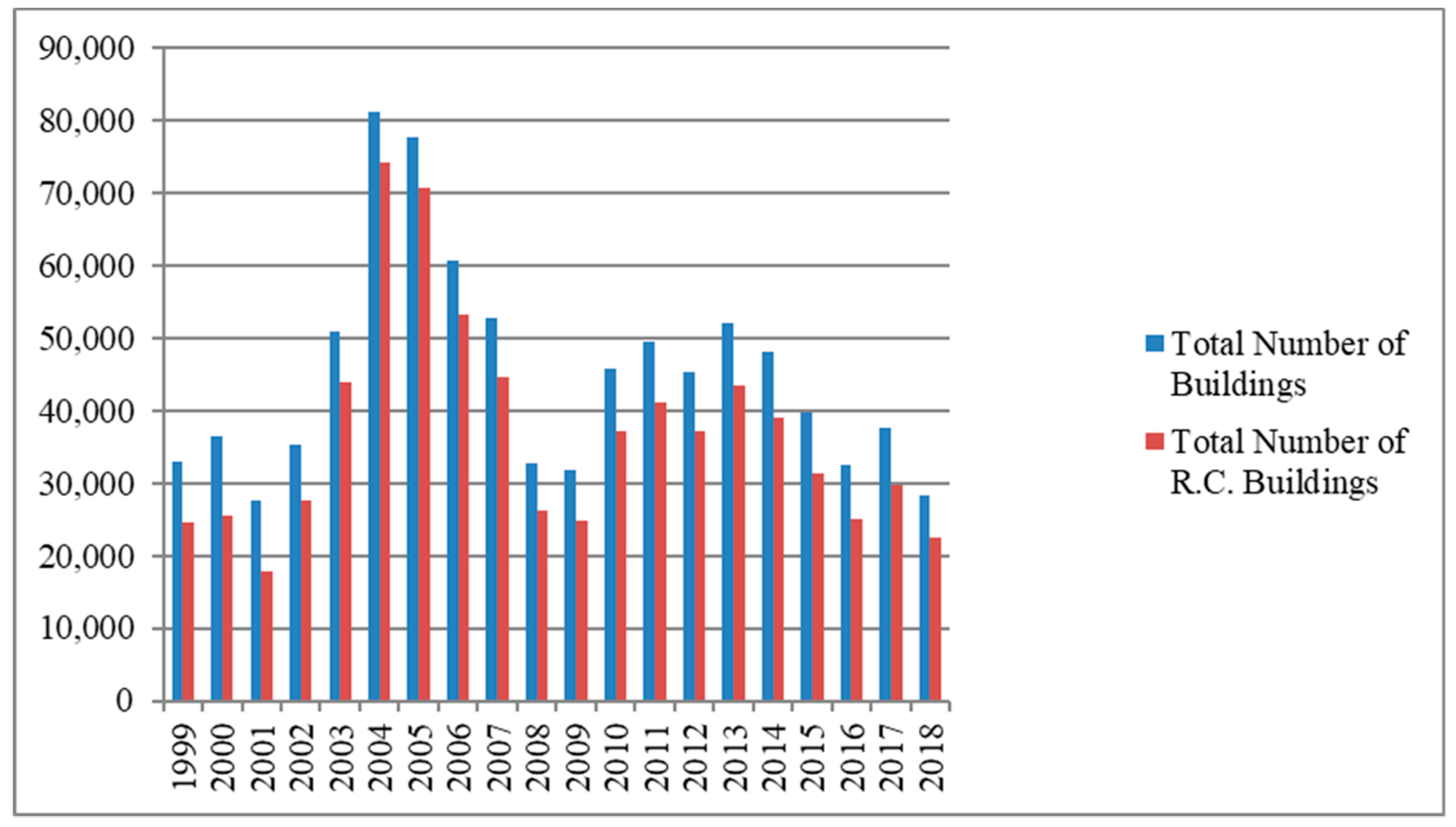
Figure 2.
Concrete spalling as a result of rebar oxidation.
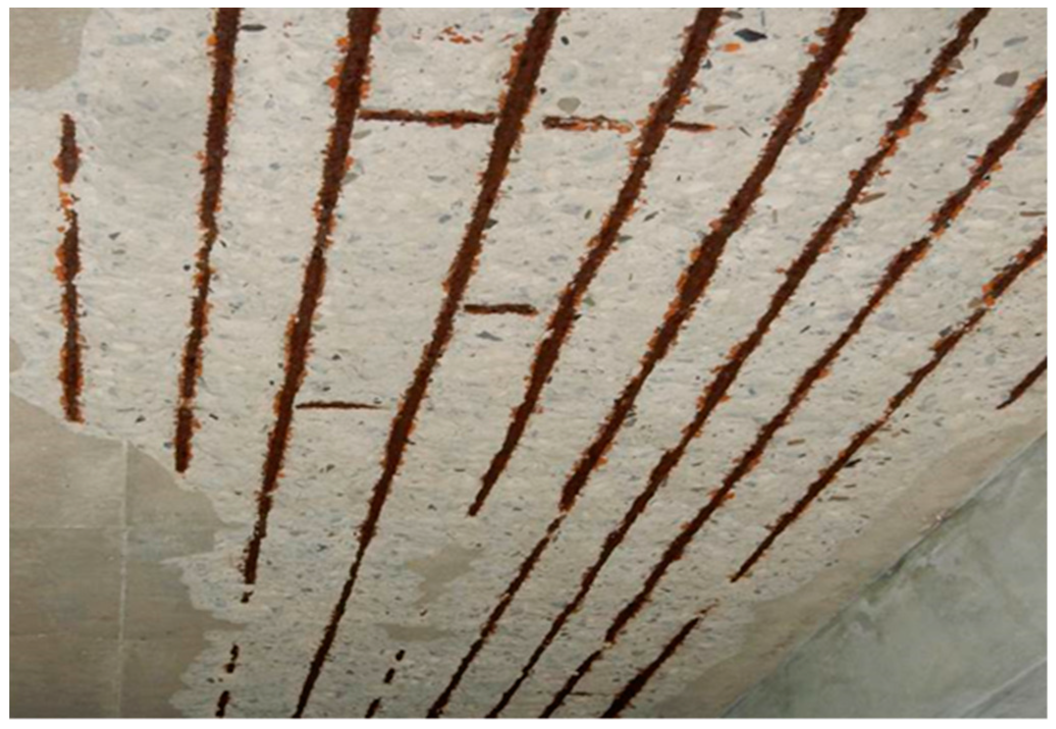
Figure 3.
Building tilt caused by an earthquake.

Figure 4.
Flowchart of structural damage assessment as well as repair and retrofit.

Figure 5.
CFRP material.
Figure 6.
Concrete surface after rust removal and cleaning.
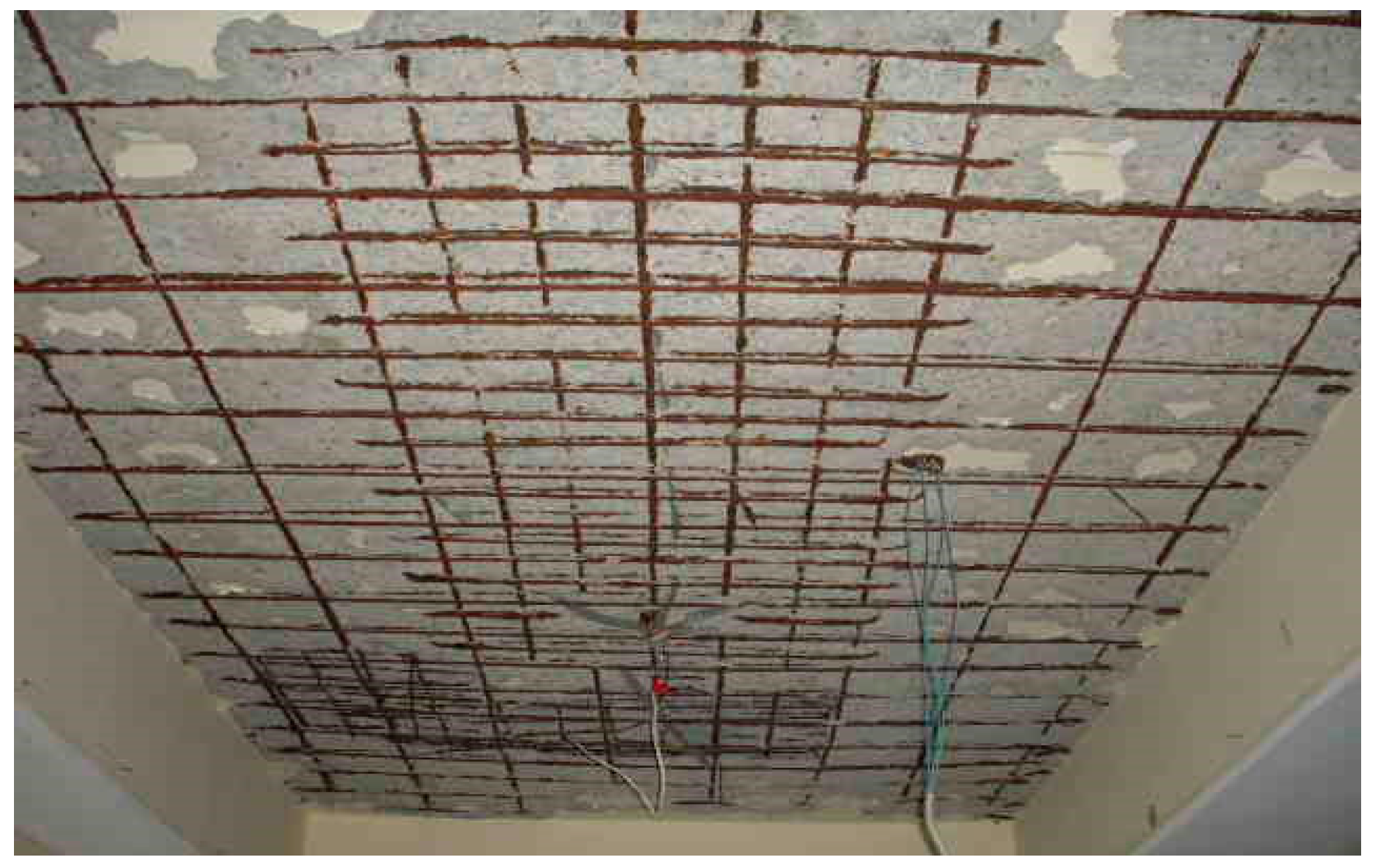
Figure 7.
Coating grout crevices at the slab base with low viscosity epoxy resin.

Figure 8.
Slab surface after repair and flattening.
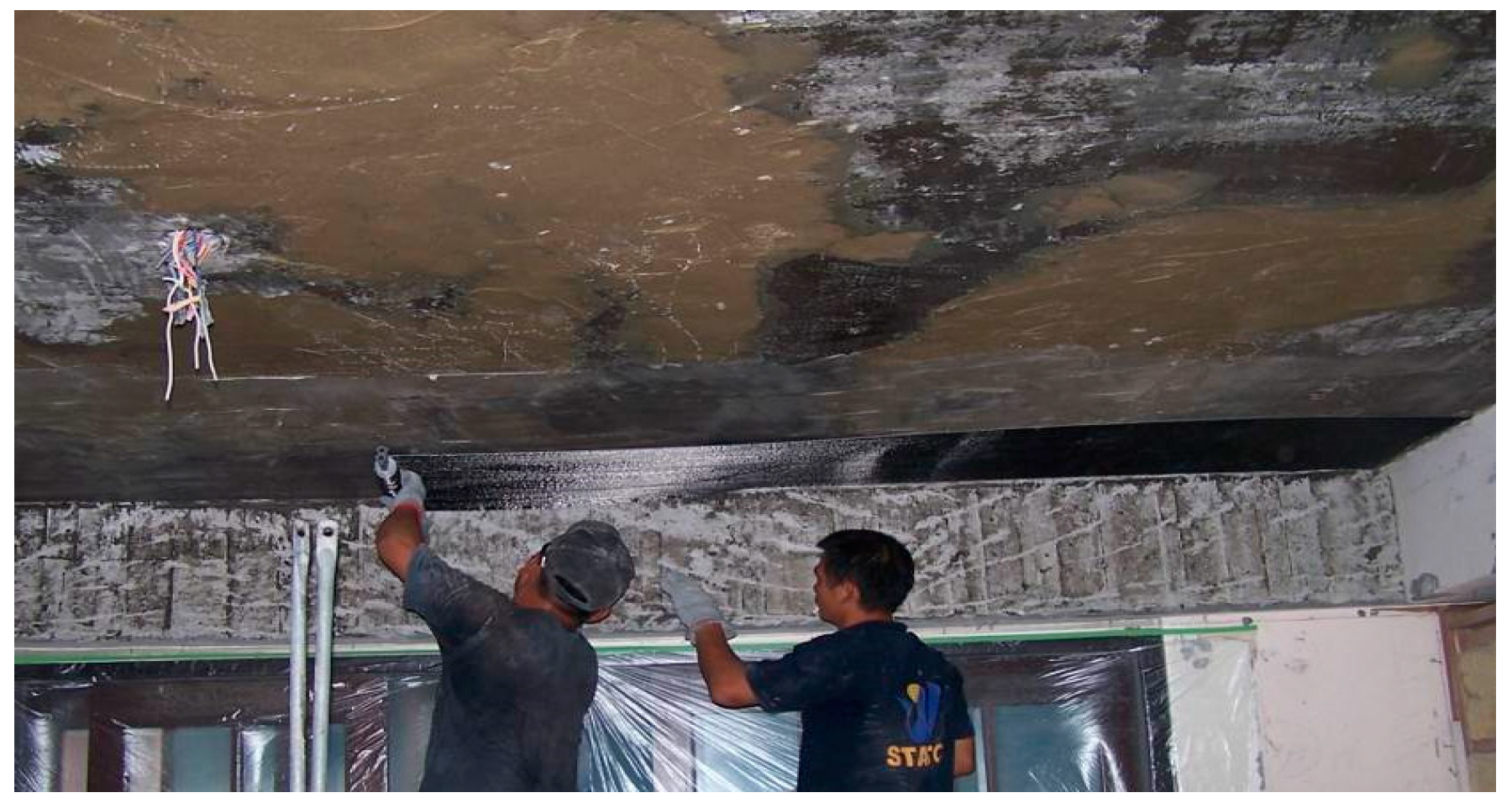
Figure 9.
After CFRP patch attachment.

Figure 10.
Affixing CFRP patches using angle steels.

Figure 11.
H-beams welded onto steel beams.

Figure 12.
Current state, photographed 10 years after repair and retrofit.


Table 1.
Classification standards of RC structural damages [17] (Chinese Institute of Civil and Hydraulic Engineering, 2005).
Table 1.
Classification standards of RC structural damages [17] (Chinese Institute of Civil and Hydraulic Engineering, 2005).
| Damage Level of RC Structures | Damage Details |
|---|---|
| I (Slight damage) | Crevices can only be identified upon close inspection (crevice width <0.2 mm) |
| II (Mild damage) | Crevices can be discerned with the naked eye (crevice width 0.2–1 mm) |
| III (Moderate damage) | Although relatively large crevices are present, spalling of the protective layer from the concrete is observed (crevice width 1–2 mm) |
| IV (Severe damage) | Numerous crevices wider than 2 mm, or severe concrete spalling is present with exposed rebars |
| V (Complete destruction) | Main rebar buckling, concrete cracking, column or shear wall vertical deformation, subsidence or tilting, or even rebar breakage |
Table 2.
Physical properties of the carbon-fiber reinforced plastic (CFRP) patches used in this study.
Table 2.
Physical properties of the carbon-fiber reinforced plastic (CFRP) patches used in this study.
| Physical Property | Glass Fiber Content (%) | Specific Weight | Tensile Strength (kg/cm²) | Compressive Strength (kg/cm²) | Bending Strength (kg/cm²) | Tensile Modulus (105 kg/cm²) | Heat Distortion Temperature (°C; Load 18.6 kg/cm²) | Combustibility |
|---|---|---|---|---|---|---|---|---|
| Value | 6070 | 1.8~2.0 | 3100~4300 | 1600~5000 | 3100~6400 | 1.8~2.5 | 120~190 | Combustible |
Table 3.
Physical properties of the epoxy resin grout.
| Category | Strength (kg/cm²) | Note |
|---|---|---|
| Compressive strength | ≥765 | |
| Adhesive strength with steel materials | ≥102 | |
| Adhesive strength with concrete | 20–30 | Approx. 10–20% of the design strength of concrete (fc’) |
| Elastic modulus | ≥9.2 × 10⁴ |
© 2019 by the authors. Licensee MDPI, Basel, Switzerland. This article is an open access article distributed under the terms and conditions of the Creative Commons Attribution (CC BY) license (http://creativecommons.org/licenses/by/4.0/).
Share and Cite
MDPI and ACS Style
Hsu, W.-L.; Liu, C.-C.; Shiau, Y.-C.; Lin, W.-C. Discussion on the Reinforcement of Reinforced Concrete Slab Structures. Sustainability 2019, 11, 1756. https://doi.org/10.3390/su11061756
AMA Style
Hsu W-L, Liu C-C, Shiau Y-C, Lin W-C. Discussion on the Reinforcement of Reinforced Concrete Slab Structures. Sustainability. 2019; 11(6):1756. https://doi.org/10.3390/su11061756
Chicago/Turabian StyleHsu, Wei-Ling, Chen-Chung Liu, Yan-Chyuan Shiau, and Wen-Chin Lin. 2019. "Discussion on the Reinforcement of Reinforced Concrete Slab Structures" Sustainability 11, no. 6: 1756. https://doi.org/10.3390/su11061756
Note that from the first issue of 2016, this journal uses article numbers instead of page numbers. See further details here.