Environmental Performance Analysis of Cement Production with CO2 Capture and Storage Technology in a Life-Cycle Perspective

1
School of Metallurgy, Liaoning Province Key Laboratory of Metallurgical Resources Recycling Science, Northeastern University, Shenyang 110819, China
2
Earth and Environmental Sciences, Los Alamos National Laboratory, Los Alamos, NM 87545, USA
*
Author to whom correspondence should be addressed.
Sustainability 2019, 11(9), 2626; https://doi.org/10.3390/su11092626
Submission received: 15 March 2019
/
Revised: 19 April 2019
/
Accepted: 1 May 2019
/
Published: 7 May 2019
(This article belongs to the Special Issue Environmental Life Cycle Assessment)
Abstract
:Cement manufacturing is one of the most energy and CO2 intensive industries. With the growth of cement production, CO2 emissions are increasing rapidly too. Carbon capture and storage is the most feasible new technology option to reduce CO2 emissions in the cement industry. More research on environmental impacts is required to provide the theoretical basis for the implementation of carbon capture and storage in cement production. In this paper, GaBi software and scenario analysis were employed to quantitatively analyze and compare the environmental impacts of cement production with and without carbon capture and storage technology, from the perspective of a life-cycle assessment; aiming to promote sustainable development of the cement industry. Results of two carbon capture and storage scenarios show decreases in the impacts of global warming potential and some environmental impacts. However, other scenarios show a significant increase in other environmental impacts. In particular, post-combustion carbon capture technology can bring a more pronounced increase in toxicity potential. Therefore, effective measures must be taken into account to reduce the impact of toxicity when carbon capture and storage is employed in cement production. CO2 transport and storage account for only a small proportion of environmental impacts. For post-combustion carbon capture, most of the environmental impacts come from the unit of combined heat and power and carbon capture, with the background production of MonoEthanolAmine contributing significantly. In combined heat and power plants, natural gas is more advantageous than a 10% coal-saving, and thermal efficiency is a key parameter affecting the environmental impacts. Future research should focus on exploring cleaner and effective absorbents or seeking the alternative fuel in combined heat and power plants for post-combustion carbon capture. If the power industry is the first to deploy carbon capture and storage, oxy-combustion carbon capture is an excellent choice for the cement industry.
1. Introduction
Cement is one of the most abundantly produced building materials, and global production has been increasing steadily since the 1950s. Global production reached 4.2 billion tons in 2016 [1], which already exceeds the predicted 2050 production by the International Energy Agency (IEA). The IEA previously predicted a production of 3.69 to 4.40 billion tons by 2050 [2]. The cement industry is one of the most energy and CO2 intensive industries, and it is the second biggest CO2 emissions source, contributing around 5% of the global greenhouse gas emissions [3]. With the growth of cement production, CO2 emissions are increasing. The IEA cement technology roadmap predicts that the cement industry could reduce 18% of its direct emissions from current levels by 2050 [2]. In order to achieve this emission reduction target, carbon capture and storage (CCS) would need to account for 56% of the emissions reduction, while other reductions would rely on increased of energy efficiency, reduction of clinker content, and the application of alternative fuels [3].
CCS involves series technologies, including CO2 captured from the combustion of fuels or certain industrial processes, CO2 transported, and CO2 stored away from the atmosphere for a very long time [4]. Since material or process replacement is not technically or economically feasible in the industrial sector [4,5], CCS is considered the technically feasible technology that can deeply reduce CO2 emissions from combustion and other major industrial processes. Accordingly, this has led to substantial research in capture technologies, storage technologies, and economic analysis. For instance, Elias et al. and Sharifzadeh et al. focused on the application of the post-combustion CO2 capture technology in power plants [6,7]. Pore-scale imaging and a 4D model were used to study the security of storage sites [8,9]. The cost of CCS for several carbon-intensive industrial processes has been evaluated and compared comprehensively [10,11]. Hitch et al. discussed how to use mine waste rock to trap and store CO2, and benefit economically from it [12,13]. In addition, the framework for spatially optimizing infrastructure for CCS was developed, since the linking of CO2 emissions sources and sequestration reservoirs are required [14,15]. Currently many demonstration projects on CCS have already been deployed in the world [16,17]. However, the widespread commercialization of CCS has not been achieved due to several barriers. The result of the reviews shows that CCS cost is the most significant barrier in the short to medium term [5,18]; other hurdles include (1) uncertainties in policies, regulations and technical performance; (2) public acceptance; and (3) concerns about human health and safety and environmental risks [18]. Consequently, more researches in the above areas are needed to aid the commercialization of CCS.
Although some obstacles need to be addressed now, CCS is still widely considered to be a promising technology choice. The IEA has proposed that CCS is the most feasible new technology to reduce CO2 emissions in the cement industry, including technical reports of the feasibility and economic cost of CCS such as [19] and [2]. According to the cement roadmap 2050, there will be a projected 10 to 15 commercial cement plants operating with carbon capture technology and 20 to 35 million tons of CO2 will be captured and stored per year by 2025. Other key studies have also examined and improved the role of CO2 capture technology in the cement industry [20,21]. Typically, cement industry studies have focused on economic cost analysis, since it is one of the key factors to affect CCS implementation [22,23]. The environmental benefit is also an essential aspect for decision-makers regarding CCS technology. However, previous CO2 capture studies have tended to focus on environmental benefits related to the energy efficiency and reduction of CO2 emissions [24,25], rather than all the potential environmental impacts.
The life-cycle assessment (LCA) is a method to assess all the potential environmental impacts of a product, process, or activity over its whole life cycle [26]. CCS technology necessarily incurs an energy penalty, as well as the introduction of some new materials. For example, post-combustion capture of MonoEthanolAmine (MEA), a popular chemical absorbent, is used to capture CO2 from flue gas, and considerable heat is required to regenerate the absorbent. Accordingly, these new materials and additional energy, or energy penalty, will incur direct or indirect background environmental impacts from the perspective of LCA. Many studies have examined these additional environmental impacts derived from CCS for power plants and chemicals production coupled with an LCA method [27]. However, for the cement industry, only a few related studies were carried out. A detailed LCA was applied to 2030 Spanish cement production with and without a post-combustion CO2 capture scenario [28]. A systematic comparison of LCA-based environmental performances of cement production in Europe for 2025 and 2050 with and without CCS was studied [29]. Impacts of different fuels, namely coal, natural gas, woody biomass, and a fuel mix, on the environmental performance of tail-calcium looping applied to the clinker production were compared, coupled with the method of LCA [30]. The life cycle environmental evaluation for the integration of calcium carbonate looping (CCL) and oxy-fuel combustion processes into a cement plant for CO2 capture was analyzed [31]. These limited studies are not sufficient since assessment results are related to many factors, such as CO2 capture technology, the scope of system boundary, and environmental impact classification method. As a result, more research on the environmental impacts is required to provide the theoretical basis for the implementation of CCS in the cement industry.
There are two CO2 emission sources in cement production: Around 50% of CO2 emissions derive from the calcination of limestone and the remaining emissions from fossil fuel combustion. CO2 concentration in cement kiln flue gases (approximately 15 to 30 mol%) is higher than the power generation industry [19], which provides advantages for capturing CO2 in cement production. Pre-combustion, post-combustion, and oxy-combustion are the three main technologies to capture CO2 in the industrial sector. Pre-combustion capture technology is not considered in this study since this technology is unable to capture the large amount of CO2 derived from the decomposition process of limestone. The preferred technologies for capturing CO2 in cement plants are post-combustion and oxy-combustion capture. This study aims to analyze and compare the environmental impacts of cement production with or without the two preferred carbon capture technologies from the perspective of LCA and to provide a theoretical basis for the sustainable development of the cement industry.
2. Methodology
2.1. System Boundary and Scenarios Designing
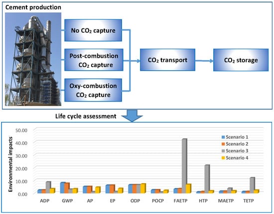
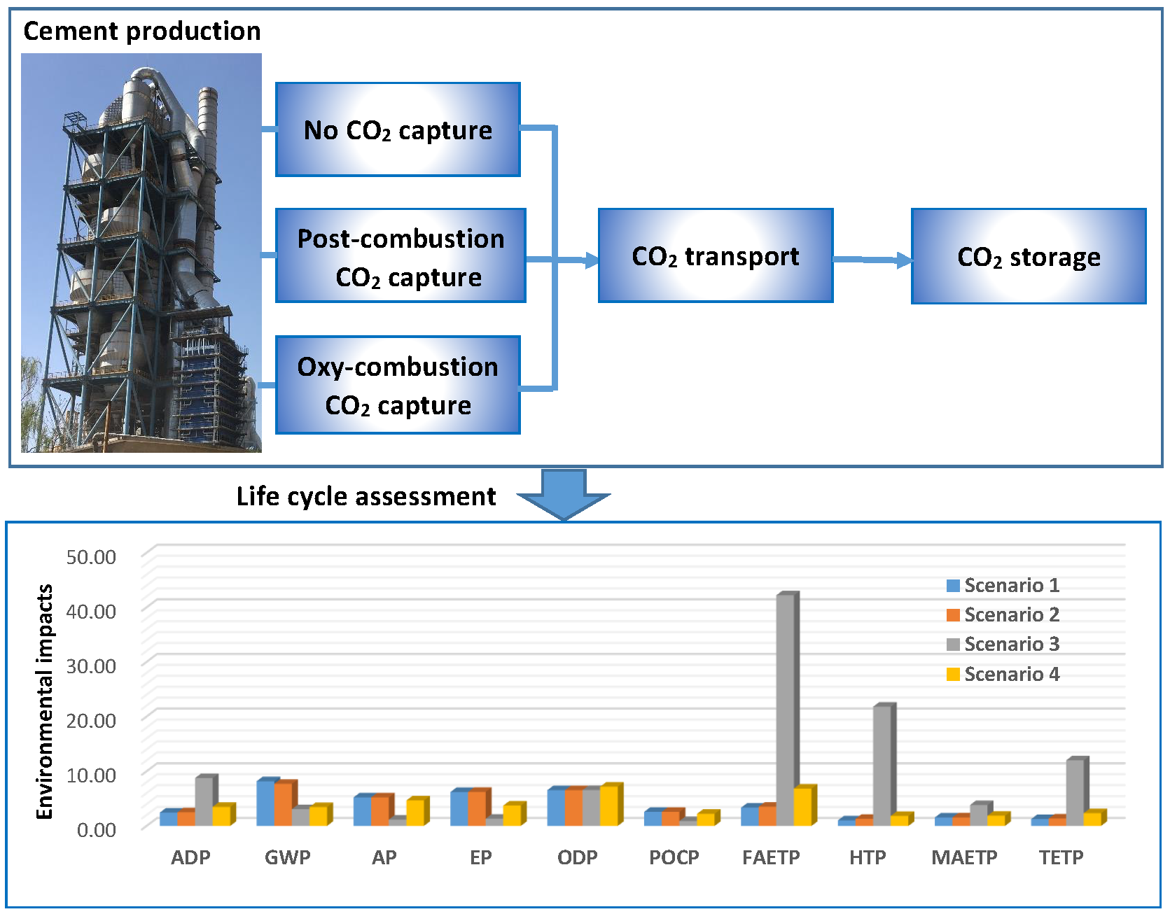
This study was based on the new-build cement plants described in the IEA technology report [19]. The main cement production processes without CO2 capture and the corresponding system boundary are showed in Figure 1.
For post-combustion CO2 capture technology, a CO2 separation process is added before the flue gas is discharged to the atmosphere. The separated high-purity CO2, after being compressed, can then be transported and stored. Chemical absorption is currently the most widely used method for capturing CO2 from low pressure and low concentration flue gases, and MEA is the most widely used chemical adsorbent [19]. Therefore, the MEA adsorption method was selected as a case study for post-combustion CO2 capture technology. Extra energy is required for MEA CO2 capture because MEA has to be regenerated by a large amount of low-pressure steam after the CO2 has been absorbed in the MEA. We assumed that steam will be supplied by an onsite combined heat and power (CHP) plant and that the plant can also meet the power requirements of the post-combustion capture process and other production processes in the cement plant. NOx and SO2 in the kiln flue gas can have negative impacts on the MEA absorption process, so they have to be reduced to the required level before the flue gas is passed to the CO2 capture unit. In this study, a selective catalytic reduction (SCR) unit is considered to eliminate NOx and a flue gas desulphurization (FDG) unit is considered to remove SO2 from the flue gas.
For oxy-combustion CO2 capture technology, fuel is burnt in almost pure oxygen rather than air. This requires an on-site air separation unit (ASU) to deliver oxygen to the oxy-combustion process. The concentration of CO2 in the flue gas produced by oxy-combustion is higher (about 80 mol%, dry basis) than that of post-combustion, so the flue gas can be transported and stored after a relatively simple purification and compression processes instead of the separation process.
CO2 transport and storage were also involved in this study because they are an integral part of CCS technology. Figure 2 and Figure 3 show the corresponding system boundary of two cement production processes with CCS. The effect of CCS applied to the power industry is considered since the application of CCS on the power industry is much more mature than that of the cement industry [32]. Four scenarios were designed within the system boundary. Here, 1000 kg cement was considered as the functional unit of each scenario. The application of CCS on power plants is considered in three of the scenarios with high electricity consumption. Coal was chosen as the main fuel in the following scenario, since it is the most widely used fuel in the world.
Scenario 1: CCS was not applied in the cement plant, and the electricity needed in the production was provided by an offsite coal-based integrated gasification combined cycle (IGCC) power plant with no CCS.
Scenario 2: CCS was not applied in the cement plant, but the electricity needed in the production was provided by an offsite hard coal-based IGCC power plant with CCS.
Scenario 3: CCS was applied in the cement plant with post-combustion CO2 capture. The electricity and steam needed in the production process and CO2 capture process was provided by an onsite coal-based IGCC CHP plant. The flue gases passed to the CO2 capture—which comes from the CHP plant and the clinker production process—unit were mixed.
Scenario 4: CCS was applied in the cement plant with oxy-combustion CO2 capture. The electricity needed in the production was provided by an offsite coal-based IGCC power plant with CCS.
2.2. Inventory Analysis
The life cycle inventory (LCI) for cement production with and without CO2 capture was based on a new-build cement plant, which was designed based on specifications in the technical report discussed above [19]. Production capacity was set to 1 Mt/y of cement and the proportion of clinker in cement products at 91%. The direct input and output data are summarized in Table 1. For the post-combustion capture case, there was a small electricity surplus in the CHP plant, which was sent to the electric grid. The offset of environmental impacts of surplus electricity were not considered in this study. SO2 and NO2 emissions from the cement production process were calculated according to the mass flowrates and operational hours of the new-build cement plant. Particulate emissions of different sizes were sourced from the ecoinvent database v3 [33]. There was a 50% reduction in particulates for the post-combustion case due to the additional FDG and SCR processes. For the CO2 transport, we chose pipelines as the case study and a transportation distance of 200 km without recompression. For the CO2 storage, we assumed CO2 was stored in a deep saline aquifer. The input and output data for transport and storage are summarized in Table 2. Due to the data unavailability, the LCI of sand, gravel, and cement were not considered in this study.
The LCI for electricity and CHP plant were sourced from a life cycle emissions database for electricity and heat generation technologies 2005/2010, 2020, and 2030 [35]. The LCI for limestone and hard coal were sourced from the professional database of GaBi. The LCI of other materials needed for cement production, as well as CO2 capture, transport, and storage were all sourced from the ecoinvent database v3 [33].
2.3. The Classification of Environmental Impacts and LCA Software
Environmental impacts were classified according to the CML2001 method, which is a widely used classification method. Classification in this study included abiotic depletion potential (fossil fuels) (ADP), global warming potential (100 years) (GWP), human toxicity potential (HTP), freshwater aquatic ecotoxicity potential (FAETP), marine aquatic ecotoxicity potential (MAETP), terrestrial ecotoxicity potential (TETP), photochemical ozone creation potential (POCP), ozone layer depletion potential (ODP), acidification potential (AP), and eutrophication potential (EP). Each environmental impact was related to specific pollutants with a normalization coefficient. GaBi 7.0, an LCA software package produced by thinkstep, was used in this study to help define the models and account for environmental impacts in the four scenarios described in Section 2.1.
3. Results and Discussion
Based on the methodology described above, the results of four scenarios are given in Table 3. The comparison results of all four scenarios are shown in Figure 4.
3.1. Scenario Comparison and Analysis
By comparing scenario 1 and scenario 2, we found that little change took place in the environmental impacts of 1 ton of cement except for GWP and HTP, if CCS was only applied in the power industry. In scenario 2, GWP decreased by 5.75% and HTP increased by 28% compared with scenario 1. However, although somewhat small, these changes could have a massive impact when considering worldwide cement production. Moreover, impacts in China and India are particularly pronounced since their cement production far exceeds all other countries.
By comparing all four scenarios, we found that the two CCS scenarios decreased the impact of GWP effectively, with GWP decreases ranging from 62.55% (scenario 3) to 57.77% (scenario 4) compared with scenario 1. Meanwhile the other environmental impacts—AP, EP, and POCP—can also be reduced very effectively. Scenario 3 had a more pronounced reduction effect than scenario 4, with a greater reduction in environmental impacts broadly. Specifically, more than 65% of the impacts were reduced for scenario 3, while around 10% reduction in AP and POCP, and EP reduction of 40% for scenario 4. However, the two CCS scenarios increased the impacts of ADP, FAETP, HTP, MAETP, and TETP significantly due to the added energy, construction, and materials for CCS technology. For scenario 3, increases ranged from 248.05% in MAETP to 2158.42% in HTP. For scenario 4, the effect was relatively small, with increases ranging from 120.78% in MAETP to 204.49% in FAETP. In addition, the implementation of CO2 capture and storage had little effect on ODP. From the above results, we can see that although post-combustion carbon capture can reduce GWP effectively, it can bring a more pronounced increase in all kinds of toxicity potential. Therefore, effective measures must be taken into account to reduce the impacts of toxicity when post-combustion carbon capture technology is employed in cement production.
3.2. Main Environmental Impact Sources Analysis
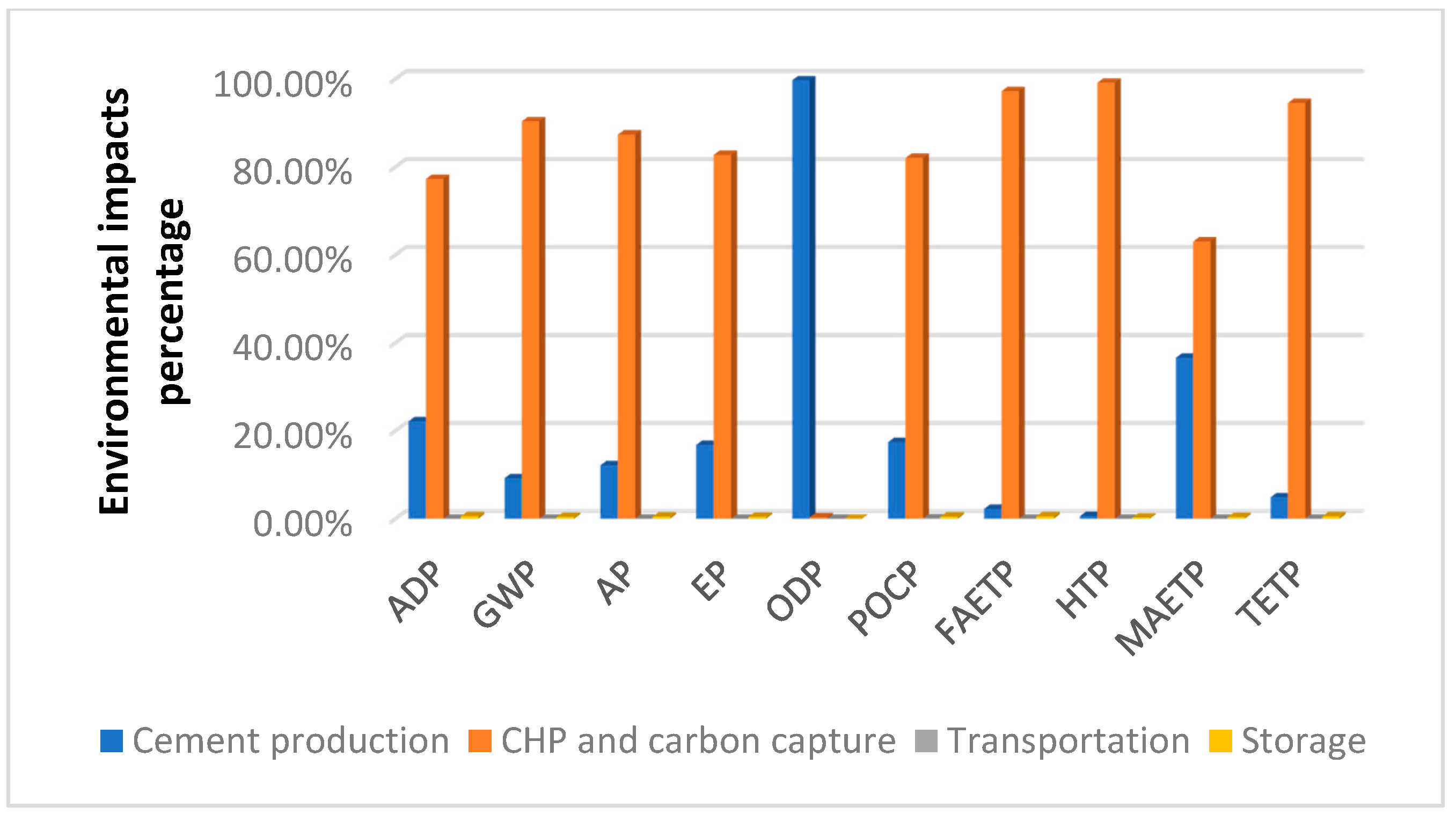
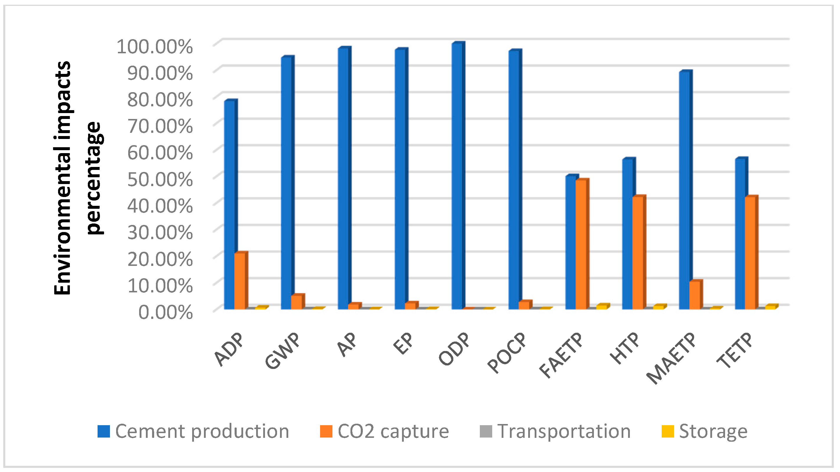
In order to analyze the environmental impacts sources of scenario 3 and scenario 4, all the production processes—including the production of background materials and energy—were classified into four units. The cement production unit includes clinker production, mixing, and the background production of limestone, petroleum coke, hard coal, gypsum, and iron oxide. The transportation unit includes CO2 transportation and the background production of diesel, steel, and rock wool. The storage unit includes CO2 storage and the background production of electricity. For scenario 3, the CHP and carbon capture unit includes all the processes of SCR, FGD, CHP, and CO2 capture and compression, as well as the background production of MEA, ammonia, limestone, and hard coal. For scenario 4, the CO2 capture unit includes the processes of ASU, CO2 purification and compression, and the background production of electricity.
The comparison of the environmental impacts sources for both scenario 3 and scenario 4 are shown in Figure 5 and Figure 6. The environmental impact of transportation and storage was minimal, regardless of the carbon capture technology. For oxy-combustion carbon capture, more than 50% of the environmental impact comes from the cement production unit. Moreover, the carbon capture unit increased ADP and every category of toxicity potential. However, for post-combustion carbon capture, more than 60% of each environmental impact comes from the unit of CHP and carbon capture, and only a small part comes from the cement production unit apart for ODP. Most of the above environmental impacts come from the combustion of hard coal to cogenerate heat and power. The only exception is HTP, because 71.52% of HTP sourced from the unit of CHP and CO2 capture comes from the background production of MEA. MEA, as a chemical adsorbent, is produced from ethylene oxide and ammonia [33], which is the mainstream production technology for MEA. The ethylene oxide released into the air and fresh water during the production process contributes most to HTP. Therefore, the amount of MEA used for adsorbent greatly contributes to the environmental impact of HTP.
3.3. CHP Improvement Analysis
Since the CHP and CO2 capture unit brings additional environmental impacts, next we discuss the potential of saving coal, and using an alternative fuel in the CHP plant. We estimate that 10% coal-saving is feasible or that natural gas, as a clean fuel, is a suitable choice for the CHP plant. Consequently, we compared the environmental impacts for the above two situations with scenario 3. As shown in Figure 7, about 3% to 10% of environmental impacts can be reduced by coal-saving, except for ODP. However, natural gas can lead to a 5% to 8% reduction in HTP, MAETP, POCP, and EP, and a 12.28% reduction in GWP. Meanwhile natural gas leads to a greater reduction in AP and TETP, 35.71% and 62.91% respectively, but it also incurs a 4.63% increase in FAETP. In general, natural gas, as an alternative fuel, is more advantageous than coal in the CHP plant.
Results show that the CO2 capture unit was not the primary contributor to environmental impacts for the oxy-combustion CO2 capture scenario. For post-combustion CO2 capture scenario, the 10% coal-saving and using natural gas as alternative fuel have been discussed. Here, another important parameter, the efficiency of CHP plant for post-combustion CO2 capture was discussed. In scenario 3, the total efficiency for the CHP plant was assumed to be 77%, which includes a thermal efficiency of 60% and an electrical efficiency of 17%. The effect of increasing thermal efficiency by 10% and decreasing by 10% was analyzed, and the results are shown in Figure 8. The electrical efficiencies of the two situations were still 17%, which means the total efficiencies were 87% and 67%, respectively since the electrical demand of the whole cement plant remained unchanged. Figure 8 indicates that the thermal efficiency had a more visible influence on ADP, AP, EP, POCP, FAETP, TETP, and MAETP, where an efficiency change of 10% changed these parameters between 10% and 20%. The thermal efficiency had less of an influence on GWP and HTP, with changes of roughly 5%. However, the efficiency of CHP had no impact on ODP.
3.4. Sensitivity Analysis
With the improvement of CO2 capture technology, the related parameters may change. Accordingly, sensitivity analysis of key parameters is necessary. For the post-combustion CO2 capture scenario, the parameters related to CHP improvement, such as 10% coal-saving, using natural gas as an alternative fuel, and the efficiency have been investigated in Section 3.3. Here, the consumption of MEA and ammonia is discussed. For the oxy-combustion CO2 capture scenario, the consumption of electricity in the process of ASU and CO2 compression is central to LCA results and should be examined. Standard deviations of 10% variation in the above key parameters are shown in Table 4. For the post-combustion CO2 capture scenario, the consumption of MEA had the greatest impact on HTP, with a standard deviation of 7.03%. Other standard deviations were all less than 1%. For oxy-combustion CO2 capture, the consumption data of electricity for ASU and for CO2 compression had more impacts on FAETP, HTP, MAETP, and TETP, with the standard deviation ranging from 2% to 5%. The two parameters contributed little to other environmental impacts.
3.5. Prospect Analysis
The widespread commercialization of CCS requires a comprehensive consideration of economic cost, the difficulty of retrofit, and environmental performance. The results of this study show that MEA-based post-combustion carbon capture can reduce more CO2 emissions and some other environmental impacts; however, it can also bring more toxicity potential to people. The above result is in line with that of another study [28], although each was based on a different classification method of environmental impact. The CML2001 method was deployed in this study and ILCD method was deployed in the reference study. Post-combustion CO2 capture technology is a promising technology since it is easy to retrofit at any cement plant. Future research should focus on exploring a cleaner and effective absorbent or seeking alternative fuel to be used in CHP plant for post-combustion carbon capture. For oxy-combustion carbon capture, more electricity is required by an air separation unit, which will bring background environmental impacts. If the power industry is the first to deploy CCS, oxy-combustion carbon capture is an excellent choice for the cement industry. Although currently, the cost is high, these two CO2 capture technologies may become economically feasible with technical improvement, such as the use of an alternative absorbent and waste heat. In addition, the introduction of some policies, such as carbon tax and carbon trading, is also helpful to promote the deployment of CO2 capture technology.
CCS is a regional measurement, rather than an activity of a single plant or a single industry sector. Carbon emission sources and storage sites need to be matched, and transport routes require systematic planning. Therefore, a scale effect can promote the development of CCS and will be necessary to carry out CO2 capture research for other CO2 emission intensive industries, such as the iron and steel industry. In addition to being stored underground, captured CO2 can also be valorized to create value-added products, such as reactive solvent and inorganic carbonates. Although the market for the CO2 valorization is small at present, it is a promising development direction, since CO2 valorization technologies can offer a unique opportunity for sustainable carbon cycle towards a circular economy [18]. Accordingly, more studies on economic cost, policy, and environmental impact of CO2 valorization are needed to compare with CCS in order to provide a more theoretical basis for effective carbon emission mitigation.
4. Conclusions
In this study, the GaBi software package and scenario analysis were used to analyze and compare the environmental impacts of cement production with and without carbon capture and storage technology from the perspective of LCA. Results show that the implementation of CCS in the power industry had minimal effect on reducing environmental impacts of each ton of cement except for GWP and HTP. However, we cannot ignore these impact changes when looking at the whole cement industry, especially for China and India, since the worldwide cement production is so large and has such a massive impact on CO2 emissions. The two CCS scenarios not only effectively decreased the impact of GWP, but also reduced the impacts of AP, EP, and POCP. However, the two CCS scenarios also increased the impacts of ADP, FAETP, HTP, MAETP, and TETP significantly. Post-combustion carbon capture technology, in particular, can bring a more pronounced increase in all kinds of toxicity potential. Therefore, effective measures must be taken into account to reduce the impacts of toxicity, when it is employed in cement production.
All the cement production processes and the background production of involved materials for the two CCS scenarios were classified into four units. We found that the units of CO2 transportation and storage accounted for a small proportion of the environmental impacts. For oxy-combustion carbon capture, most of environmental impacts come from the unit of cement production. For post-combustion carbon capture, most of the environmental impacts come from the unit of CHP and carbon capture, especially the combustion process of hard coal to cogenerate heat and power. However, the background production of MEA was shown to have a significant contribution to the environmental impacts of HTP.
As a clean fuel, natural gas can reduce a small amount of HTP, MAETP, POCP, and EP, compared with the 10% coal-saving scenario. Furthermore, it can also reduce a large amount of AP and TETP at the same time. In general, natural gas, as an alternative fuel, is much more advantageous than coal-saving in the CHP plant. In addition, the thermal efficiency of the CHP plant for post-combustion capture has a more visible influence on LCA results. The effect of increasing thermal efficiency by 10% and decreasing by 10% was analyzed, and the results show that the thermal efficiency had a substantial influence on ADP, AP, EP, POCP, FAETP, TETP, and MAETP, though it had less influence on GWP and HTP, and no impact on ODP. Consequently, the thermal efficiency of the CHP plant is a key parameter for reducing environmental impacts.
Prospect analysis shows that future research should focus on exploring a cleaner and effective absorbent or seeking an alternative fuel in the CHP plant for post-combustion carbon capture. Oxy-combustion carbon capture would be an excellent choice for the cement industry if the power industry is the first to deploy CCS. It is necessary to carry out CO2 capture research for other CO2 emission-intensive industries to promote the development of CCS on a regional scale. In order to provide a more reliable theoretical basis for effective carbon emission mitigation and sustainable development of the cement industry, more studies on economic cost, policy, and environmental impact of CO2 valorization are needed to compare with CCS.
This study also includes uncertainties that should be considered in future research. Rather than using a realized cement plant with CCS, the two CO2 capture technologies of post-combustion absorption and oxy-combustion were assessed based on the technical report of IEA, which potentially lead to some deviation in the LCA results. Moreover, different fuels and materials used in the cement production or CCS process will also affect the LCA results. More extensive demonstration projects of the cement industry with CCS will provide more reliable data for environmental analysis.
Author Contributions
Conceptualization, J.A.; methodology, J.A. and R.S.M.; software, J.A. and Y.L.; formal analysis, J.A. and Y.L.; investigation, J.A.; writing—original draft preparation, J.A.; writing—review and editing, R.S.M.
Funding
This research was funded by National Natural Science Foundation of China, grant number 41601609.
Acknowledgments
Gratitude goes to the support received from the China Scholarship Council.
Conflicts of Interest
The authors declare no conflict of interest.
References
- U.S. Geological Survey (USGS). Cement Statistics and Information. 2017. Available online: https://minerals.usgs.gov/minerals/pubs/commodity/cement/mcs-2017-cemen.pdf (accessed on 11 August 2017).
- International Energy Agency (IEA). Cement Technology Roadmap: Carbon Emissions Reductions up to 2050. 2009. Available online: https://doi.org/10.1787/9789264088061-en (accessed on 15 August 2017).
- IEA GHG. Deployment of CCS in the Cement Industry. 2013. Available online: https://www.ieaghg.org/publications/technical-reports (accessed on 16 August 2017).
- Intergovernmental Panel on Climate Change (IPCC). IPCC Special Report on Carbon Dioxide Capture and Storage: Prepared by Working Group III of the Intergovernmental Panel on Climate Change; Metz, B., Davidson, O., de Coninck, H.C., Loos, M., Meyer, L.A., Eds.; Cambridge University Press: Cambridge, UK; New York, NY, USA, 2005. [Google Scholar]
- Budinis, S.; Krevor, S.; Dowell, M.N.; Brandon, N.; Hawkes, A. An assessment of CCS costs, barriers and potential. Energy Strategy Rev. 2018, 22, 61–81. [Google Scholar] [CrossRef]
- Elias, R.S.; Wahab, M.I.M.; Fang, L. Retrofitting carbon capture and storage to natural gas-fired power plants: A real-options approach. J. Clean. Prod. 2018, 192, 722–734. [Google Scholar] [CrossRef]
- Sharifzadeh, M.; Bumb, P.; Shah, N. Carbon capture from pulverized coal power plant (PCPP): Solvent performance comparison at an industrial scale. Appl. Energy 2016, 163, 423–435. [Google Scholar] [CrossRef] [Green Version]
- Andrew, M.; Bijeljic, B.; Blunt, M. Pore-scale imaging of geological carbon dioxide storage under in situ conditions. Geophys. Res. Lett. 2013, 40, 3915–3918. [Google Scholar] [CrossRef] [Green Version]
- Fornel, A.; Estublier, A. To a dynamic update of the Sleipner CO2 storage geological model using 4D seismic data. Energy Procedia 2013, 37, 4902–4909. [Google Scholar] [CrossRef]
- Rubin, E.S.; Zhai, H. The cost of carbon capture and storage for natural gas combined cycle power plants. Environ. Sci. Technol. 2012, 46, 3076–3084. [Google Scholar] [CrossRef]
- Kuramochi, T.; Ramίrez, A.; Turkenburg, W.; Faaij, A. Comparative assessment of CO2 capture technologies for carbon-intensive industrial processes. Prog. Energy Combust. Sci. 2012, 38, 87–112. [Google Scholar] [CrossRef]
- Hitch, M.; Ballantyne, S.M.; Hindle, S.R. Revaluing mine waste rock for carbon capture and storage. Int. J. Min. Reclam. Environ. 2010, 24, 64–79. [Google Scholar] [CrossRef] [Green Version]
- Hitch, M.; Dipple, G.M. Economic feasibility and sensitivity analysis of integrating industrial-scale mineral carbonation into mining operations. Miner. Eng. 2012, 39, 268–275. [Google Scholar] [CrossRef]
- Middleton, R.S.; Bielicki, J.M. A scalable infrastructure model for carbon capture and storage: SimCCS. Energy Policy 2009, 37, 1052–1060. [Google Scholar] [CrossRef]
- Middleton, R.S.; Kuby, M.J.; Bielicki, J.M. Generating candidate networks for optimization: The CO2 capture and storage optimization problem. Comput. Environ. Urban Syst. 2012, 36, 18–29. [Google Scholar] [CrossRef]
- Kelektsoglou, K. Carbon capture and storage: A review of mineral storage of CO2 in Greece. Sustainability 2018, 10, 4400. [Google Scholar] [CrossRef]
- Zhao, X.L.; Ma, R.; Zhang, F.; Zhong, Z.C.; Wang, B.D.; Wang, Y.S.; Li, Y.L.; Weng, L. The latest monitoring progress for Shenhua CO2 storage project in China. Int. J. Greenh. Gas Control 2017, 60, 199–206. [Google Scholar] [CrossRef]
- Pan, S.Y.; Chiang, P.C.; Pan, W.; Kim, H. Advances in state-of-art valorization technologies for captured CO2 toward sustainable carbon cycle. Crit. Rev. Environ. Sci. Technol. 2018, 48, 471–534. [Google Scholar] [CrossRef]
- IEA Greenhous Gas R&D Programme (IEA GHG). CO2 Capture in the Cement Industry. 2008. Available online: http://documents.ieaghg.org/index.php/s/YKm6B7zikUpPgGA?path=%2F2008 (accessed on 5 September 2017).
- Dubois, L.; Laribi, S.; Mouhoubi, S.; De Weireld, G.; Thomas, D. Study of the post-combustion CO2 capture applied to conventional and partial oxy-fuel cement plants. Energy Procedia 2017, 114, 6181–6196. [Google Scholar] [CrossRef]
- De Lena, E.; Spinelli, M.; Romano, M.C. CO2 capture in cement plants by “Tail-End” Calcium Looping process. Energy Procedia 2018, 148, 186–193. [Google Scholar] [CrossRef]
- Li, J.; Tharakan, P.; Macdonald, D.; Liang, X. Technological, economic and financial prospects of carbon dioxide capture in the cement industry. Energy Policy 2013, 61, 1377–1387. [Google Scholar] [CrossRef]
- Jakobsen, J.; Roussanaly, S.; Anantharaman, R. A techno-economic case study of CO2 capture, transport and storage chain from a cement plant in Norway. J. Clean. Prod. 2017, 144, 523–539. [Google Scholar] [CrossRef]
- Vatopoulos, K.; Tzimas, E. Assessment of CO2 capture technologies in cement manufacturing process. J. Clean. Prod. 2012, 32, 251–261. [Google Scholar] [CrossRef]
- Cormos, A.M.; Cormos, C.C. Reducing the carbon footprint of cement industry by post-combustion CO2 capture: Techno-economic and environmental assessment of a CCS project in Romania. Chem. Eng. Res. Des. 2017, 123, 230–239. [Google Scholar] [CrossRef]
- ISO. ISO 14044: Environmental Management—Life Cycle Assessment Requirements and Guidelines; ISO: Geneva, Switzerland, 2006. [Google Scholar]
- Baena-Moreno, F.M.; Rodríguez-Galán, M.; Vega, F.; Alonso-Fariñas, B.; Vilches Arenas, L.F.; Navarrete, B. Carbon capture and utilization technologies: A literature review and recent advances. Energy Sources Part A Recov. Utilization Environ. Effects 2019, 41, 1403–1433. [Google Scholar] [CrossRef]
- García-Gusano, D.; Garraín, D.; Herrera, I.; Cabal, H.; Lechón, Y. Life cycle assessment of applying CO2 post-combustion capture to the Spanish cement production. J. Clean. Prod. 2015, 104, 328–338. [Google Scholar] [CrossRef]
- Volkart, K.; Bauer, C.; Boulet, C. Life cycle assessment of carbon capture and storage in power generation and industry in Europe. Int. J. Greenh. Gas Control 2013, 16, 91–106. [Google Scholar] [CrossRef]
- Schakel, W.; Hung, C.R.; Tokheim, L.A.; Strønnm, A.H.; Worrell, E.; Ramírez, A. Impact of fuel selection on the environmental performance of post-combustion calcium looping applied to a cement plant. Appl. Energy 2018, 210, 75–87. [Google Scholar] [CrossRef]
- Rolfe, A.; Huang, Y.; Haaf, M.; Pita, A.; Rezvani, S.; Dave, A.; Hewitt, N.J. Technical and environmental study of calcium carbonate looping versus oxy-fuel options for low CO2 emission cement plants. Int. J. Greenh. Gas Control 2018, 75, 85–97. [Google Scholar] [CrossRef]
- International Energy Agency (IEA). Technology Roadmap-Carbon Capture and Storage-2013 Edition. Available online: https://webstore.iea.org/technology-roadmap-carbon-capture-and-storage-2013 (accessed on 15 August 2017).
- [Dataset] Institutes of the ETH Domain and the Swiss Federal Offices. Ecoinvent Database v3. Available online: http://www.ecoinvent.org/database/ecoinvent-33/ecoinvent-33.html (accessed on 15 April 2018).
- Wildbolz, C. Life Cycle Assessment of Selected Technologies for CO2 Transport and Sequestration. Diploma Thesis, Swiss Federal Institute of Technology, Zurich, Switzerland, 2007. [Google Scholar]
- [Dataset] University of Stuttgart—Institute of Energy Economics and the Rational Use of Energy—IER, 2008. Cost Assessment of Sustainable Energy Systems: Database on life cycle emissions for electricity and heat generation technologies 2005/2010, 2020 and 2030. Version updated to 15th May 2008. Available online: http://www.feem-project.net/cases/downloads_presentation.php (accessed on 10 September 2017).
Figure 1.
System boundary of cement production without CO2 capture.

Figure 2.
System boundary of cement production with post-combustion carbon capture and storage (CCS).
Figure 2.
System boundary of cement production with post-combustion carbon capture and storage (CCS).

Figure 3.
System boundary of cement production with oxy-combustion CCS.

Figure 4.
Comparison results of four scenarios.

Figure 5.
Comparison of the environmental impacts sources for post-combustion CO2 capture.

Figure 6.
Comparison of the environmental impacts sources for oxy-combustion CO2 capture.

Figure 7.
Comparison of 10% coal-saving and natural gas used as fuel in CHP plant.

Figure 8.
The effect of increasing thermal efficiency by 10% and decreasing by 10%.


Table 1.
The direct input and output data of cement production with/without CO2 capture.
| Materials/Fuels/Energy | Unit | Base Production | Post-Combustion | Oxy-Combustion | |
|---|---|---|---|---|---|
| Inputs | Coal a | Kg/t cement | 63.30 | 291.60 | 72.06 |
| Petroleum coke a | Kg/t cement | 31.90 | 31.90 | 27.09 | |
| Electricity a | (kWh/t cement) | 80.81 | −22.73 | 174.56 | |
| Limestone a | Kg/t cement | 1245.97 | 1258.51 | 1256.74 | |
| Iron oxide a | Kg/t cement | 7.47 | 7.47 | 7.54 | |
| Gypsum a | Kg/t cement | 40.00 | 23.63 | 40 | |
| Ammonia a | Kg/t cement | 0 | 1.85 | 0 | |
| MEA a | Kg/t cement | 0 | 2.24 | 0 | |
| Outputs | Cement products a | Kg/t cement | 1000.00 | 1000.00 | 1000.00 |
| CO2 captured a | Kg/t cement | 0 | 1067.73 | 465.01 | |
| CO2 emitted a | Kg/t cement | 728.40 | 188.42 | 282.85 | |
| SO2 emitted b | Kg/t cement | 2.28 | 0 | 2.57 | |
| NO2 emitted b | Kg/t cement | 4.56 | 0 | 2.57 | |
| Particulates, <2.5um c | Kg/t cement | 0.0219 | 0.0109 | 0.0219 | |
| Particulates, >10um c | Kg/t cement | 0.0052 | 0.0026 | 0.0052 | |
| Particulates, >2.5um, and <10um c | Kg/t cement | 0.0072 | 0.0036 | 0.0072 |
Table 2.
Life cycle inventory (LCI) data of CO2 transportation and storage.
| Processes | Input/Output | Materials/Energy | Units | Amount |
|---|---|---|---|---|
| Transportation | Input | Diesel, burned in building machine | MJ/km | 3.31E + 06 |
| Input | Steel, low-alloyed, at plant | kg/km | 2.70E + 05 | |
| Input | Rock wool, packed, at plant | kg/km | 5.12E + 03 | |
| Output | CO2, leaked | kg/km | 2.60E − 04 | |
| Storage | Input | electricity | kWh/kg CO2 | 6.68E − 03 |
Data taken from [34].
Table 3.
Environmental impacts calculation results of four scenarios.
| Units | Scenario 1 | Scenario 2 | Scenario 3 | Scenario 4 | |
|---|---|---|---|---|---|
| Abiotic depletion potential (ADP) | MJ | 2.44 × 10³ | 2.50 × 10³ | 8.75 × 10³ | 3.48 × 10³ |
| Global warming potential (GWP) | kg CO2-Equiv. | 8.17 × 10² | 7.70 × 10² | 3.06 × 10² | 3.45 × 10² |
| Acidification potential (AP) | kg SO2-Equiv. | 5.21 × 100 | 5.22 × 10⁻¹ | 1.15 × 100 | 4.67 × 100 |
| Eutrophication potential (EP) | Kg Phosphate-Equiv. | 6.20 × 10⁻¹ | 6.22 × 10⁻¹ | 1.32 × 10⁻¹ | 3.73 × 10⁻¹ |
| Ozone Layer Depletion Potential (ODP) | kg R11-Equiv. | 6.53 × 10⁻¹¹ | 6.53 × 10⁻¹¹ | 6.55 × 10⁻¹¹ | 7.18 × 10⁻¹¹ |
| Photochem Ozone Creation Potential (POCP) | kg Ethene-Equiv. | 2.58 × 10⁻¹ | 2.57 × 10⁻¹ | 8.90 × 10⁻² | 2.22 × 10⁻¹ |
| Freshwater Aquatic Ecotoxicity Potential (FAETP) | kg DCB-Equiv. | 3.34 × 10⁻¹ | 3.51 × 10⁻¹ | 4.22 × 10⁻¹ | 6.83 × 10⁻¹ |
| Human Toxicity Potential (HTP) | kg DCB-Equiv. | 1.01 × 101 | 1.30 × 101 | 2.18 × 10² | 1.82 × 101 |
| Marine Aquatic Ecotoxicity Potential (MAETP) | kg DCB-Equiv. | 1.54 × 10³ | 1.55 × 10³ | 3.82 × 10³ | 1.86 × 10³ |
| Terrestric Ecotoxicity Potential (TETP) | kg DCB-Equiv. | 1.25 × 10⁻¹ | 1.35 × 10⁻¹ | 1.20 × 100 | 2.33 × 10⁻¹ |
Table 4.
Standard deviations of 10% variation in key parameters.
| Parameters | Post-Combustion CO2 Capture | Oxy-Combustion CO2 Capture | ||
|---|---|---|---|---|
| MEA | Ammonia | Electricity for ASU | Electricity for CO2 Compression | |
| GWP | 0.00% | 0.12% | 1.50% | 2.23% |
| AP | 0.01% | 0.04% | 0.72% | 1.07% |
| EP | 0.44% | 0.05% | 0.86% | 1.28% |
| ODP | 0.00% | 0.00% | 0.00% | 0.00% |
| POCP | 0.00% | 0.05% | 0.99% | 1.47% |
| FAETP | 0.20% | 0.00% | 3.21% | 4.76% |
| HTP | 7.03% | 0.00% | 3.15% | 4.67% |
| MAETP | 0.00% | 0.08% | 2.16% | 3.20% |
| TETP | 0.00% | 0.00% | 3.15% | 4.66% |
© 2019 by the authors. Licensee MDPI, Basel, Switzerland. This article is an open access article distributed under the terms and conditions of the Creative Commons Attribution (CC BY) license (http://creativecommons.org/licenses/by/4.0/).
Share and Cite
MDPI and ACS Style
An, J.; Middleton, R.S.; Li, Y. Environmental Performance Analysis of Cement Production with CO2 Capture and Storage Technology in a Life-Cycle Perspective. Sustainability 2019, 11, 2626. https://doi.org/10.3390/su11092626
AMA Style
An J, Middleton RS, Li Y. Environmental Performance Analysis of Cement Production with CO2 Capture and Storage Technology in a Life-Cycle Perspective. Sustainability. 2019; 11(9):2626. https://doi.org/10.3390/su11092626
Chicago/Turabian StyleAn, Jing, Richard S. Middleton, and Yingnan Li. 2019. "Environmental Performance Analysis of Cement Production with CO2 Capture and Storage Technology in a Life-Cycle Perspective" Sustainability 11, no. 9: 2626. https://doi.org/10.3390/su11092626
Note that from the first issue of 2016, this journal uses article numbers instead of page numbers. See further details here.