Review of Wave Energy Converter and Design of Mooring System


1
State Key Laboratory of Coastal and Offshore Engineering, Dalian University of Technology, Dalian 116024, China
2
Sortec Offshore Pte. Ltd., Singapore 677670, Singapore
*
Author to whom correspondence should be addressed.
Sustainability 2020, 12(19), 8251; https://doi.org/10.3390/su12198251
Submission received: 12 September 2020
/
Revised: 29 September 2020
/
Accepted: 4 October 2020
/
Published: 7 October 2020
(This article belongs to the Special Issue Renewable Energy and Environmental Pollution)
Abstract
:In recent decades, the emphasis on renewable resources has grown considerably, leading to significant advances in the sector of wave energy. Nevertheless, the market cannot still be considered as commercialized, as there are still other obstacles in the mooring system for wave energy converters (WECs). The mooring system must be designed to not negatively impact the WEC’s efficiency and reduce the mooring loads. Firstly, the overview of the types of wave energy converters (WECs) are classified through operational principle, absorbing wave direction, location, and power take-off, respectively, and the power production analysis and design challenges of WECs are summarized. Then, the mooring materials, configurations, requirements, and the modeling approaches for WECs are introduced. Finally, the design of mooring systems, including the design considerations and standards, analysis models, software, current research focus, and challenges are discussed.
1. Introduction
The sea surface waves provide a large amount of green energy and could make an enormous difference to global energy demands going toward the sustainable world. One of the factors that makes waves desirable for harvest is that they have tremendous power density compared to many renewable energy sources [1]. Wave energy seems to have the second-highest potential of all ocean clean energy sources [2,3]. The theoretical potential of wave energy is shown in Table 1. Wave energy sources have been evaluated at global [4,5,6] and regional [7,8,9,10] levels and the volume of wave energy available is high enough to stimulate significant interest in exploitation. The estimated worldwide demand in 2014 for electrical energy reached 19,800 TWh/year [11] with a worldwide wave energy reserve of the same extent [12]. However, estimates of theoretically usable wave energy capacity on a worldwide scale are widely recorded between 2000 and 4000 TWh/year [13]. Environmental problems, including air pollution, global warming, and severe weather, due to colossal fossil oil use are gradually being discussed. For electricity generation in 2040, fossil fuels are expected to account for greater than 35% of the total energy consumption [14]. In this sense, it is much more essential to harness renewable energy sources such as wind, solar, and ocean wave energy.
China, America, India, and European countries are on the frontline of establishing strategies for incorporating the wave energy of the ocean into their systems [15]. Government agencies within these countries funded studies to carry out resource assessments [16] and provided test sites and laboratories for the development and planning of energy conversion systems [17,18,19]. Apart from state-funded studies, some studies are conducted by universities [20], private organizations [21], research centers [22], and individuals who are all involved in an attempt to promote ocean energy into the public consciousness of a renewable energy sector. Due to the immense potential of wave energy [1], a wide range of wave energy converter (WEC) ideas has been formed to capture energy from waves. It is noted that now there are more than 1000 WEC prototypes [23,24]. Different studies have identified challenges resulting from the volatility of the properties of ocean waves and the sustainability of energy converters of the waves in a severe ocean environment [25].
The stability of the wave energy converter requires a mooring system. Present mooring systems and design specifications cannot completely fulfill the demands of the offshore WECs. It is according to the four properties of the wave energy converters which place them apart from the other offshore installations: function, operation, investment/revenue relationship, and the consequences in the event of failure. In the case of offshore WECs, the failures of a mooring system seem to be minor compared to offshore platforms. As such, strict safety requirements are not required. However, recommended offshore standards are needed for the implementation, and this results in the total investment between 18% [26] to 30% [27] in mooring systems. To optimize the energy efficiency of the wave energy converters, they need to be deployed to high-energy zones. Those are areas where the wave condition is high and, as a result, where a converter and also its mooring mechanism would be under extreme loading. Some of the WEC types are motion-dependent that require oscillations in waves, mostly in resonance, to obtain energy. Such oscillations will cause a mooring system to make high amplitude motions at a high frequency, causing higher dynamic tensions in mooring lines, mainly when it is in resonance. The performance of the motion-dependent devices is affected by the mooring system, because as mooring lines adding their mass (added mass), damping, and stiffness it changes the dynamic responses of WECs. The mooring system mass and stiffness are not detrimental and may also increase the performance of the converter, as stated in reference [28]. In addition, the additional mooring damping, contributing to the stabilization of floating structures [29], dissipates energy that may be exploited by WECs that are motion dependent.
An excellent mooring system for floating WECs will consider not only the possible consequences of the power take-off and device motions and but also ensure stability, be easy to maintain and monitor, and reduce installation and material costs. In this paper, the overview of the types of WECs and their mooring configurations, components, requirements, modeling approach, design consideration, suitable software, and challenges are discussed.

Table 1.
Global resources of wave energy [30].
Table 1.
Global resources of wave energy [30].
| World Regions | Wave Energy Potential (TWh/y) |
|---|---|
| Asia | 6200 |
| New Zealand, the Pacific Islands, and Australia | 5600 |
| South America | 4600 |
| North America and Greenland | 4000 |
| Africa | 3500 |
| Western and Northern Europe | 2800 |
| Central America | 1500 |
| The Mediterranean Sea and Atlantic Archipelagos | 1300 |
| Total | 29,500 |
2. WECs
The conversion of wave energy into useful energy, such as electricity, is performed through WECs.
2.1. Historical Background
The prospect of conversion of wave energy to useful energy has encouraged various inventors: by 1980, more than 1000 patents were already registered [31] and since then, the number had risen considerably. In 1799, Girard filed the earliest best known such patent in France [32]. By the late-twentieth century, several patents relating to the conversion of wave energy were in existence [33]. Former Japanese naval chief Yoshio Masuda can be called the founder of advanced wave energy development. He developed a navigation buoy equipped with a wave-driven air turbine. Such buoys are the components of the oscillating water column (OWC) [34]. The revival of wave energy work within the 1970s–1980s was mainly a result of oil crises in 1973, and the crises generated recognition of the spatial and temporal importance of the reserves of fossil fuel to policymakers and governments [35,36]. Governments [37,38] and intergovernmental associations, thus, spearheaded several developments and research activities. The 1973 oil crisis sparked a significant shift in the scenario of renewable energies and increased interest in wave energy generation on a full scale. In 1974, Stephen Salter introduced wave energy to the community of researchers and had become a landmark [39].
Several articles on the conversion of wave energy were written as books, journal papers, reports, and conference papers, such as McCormick’s pioneering book [31], released in 1981, and the books of Shaw [40], Justus and Charlier [41] (finished wave energy long chapter in 1986), Cruz [42], Ross [32], and Brooke [43]. In 1999, a report prepared by the Energy Department of the UK [2] and final report on wave energy (2003) [44] from the Thematic Network of European (European-Commission-funded project) provide a wide variety of data. Shorter reviews are available [45,46,47].
2.2. Wave Energy Converter Classifications
To date, numerous different methods have been developed to convert the wave energy to electrical energy. Around 53 different technologies of wave energy were reported in reference [48] in 2006. Typically, they are classified as per conversion type. The classifications of WECs are more in detail in references [49,50,51].
2.2.1. Operational Principle
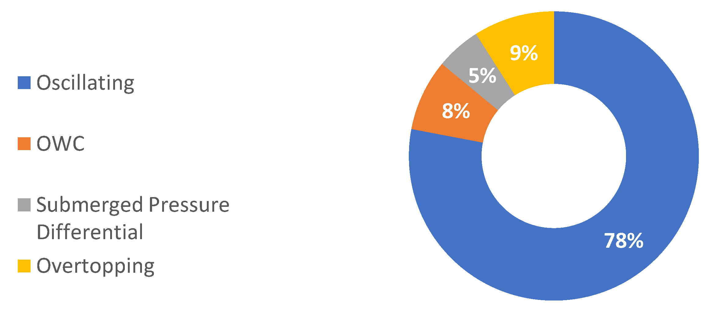
The operating principle describes how the wave energy converter interacts and absorbs energy from incoming waves. Falcão has proposed classification by operating principle [52].
Oscillating water column (OWC): The OWC is a floating hollow or fixed device that compresses and decompresses compressed air using the change in wave induced in the water level within the chamber [53], as shown in Figure 1. The pressure difference in the chamber forces air to move via a turbine that is coupled with the generator. If built near the shore, OWCs will act like breakwater structures to secure the coastline [54]. Some OWC devices have a natural installation advantage when installed close to the shore. Some examples are Energetech [55], OceanLinx [56], WaveGen Limpet [57], Yongsoo Power Plant [53], and Pico OWC [58]. Some examples of floating OWCs include Mighty Whale [59], the Spar Buoy [60], and Backward Bent Duct Buoy [61].
Oscillating bodies: Oscillating body is a generic term used to identify WECs that derive power from wave-induced oscillations of submerged or floating structures primarily in surge or heave.
Heaving type devices are commonly constructed as axisymmetric buoys just below or on the surface of the water, extracting power from the wave’s vertical motion. A total of 74 listed companies of wave energy by the Marine Energy Centre in Europe [63] concentrate on the production of heaving type point absorbers. These include Cor Power WEC (floating WEC of bottom-referenced connected to pneu-mechanical drive) [64], Power Buoy [65] (floating system of two-body self-referenced with hydraulic power take-off (PTO), as shown in Figure 2), the CETO system [66] (submerged converter of bottom-referenced with hydraulic PTO), and Sea-based wave energy converter [67] (floating system of bottom-referenced coupled with linear generator).
Oscillating wave surge (OWSC) converters are made up of the flapping structure, for example, as a plate, hinged on the seafloor or submerged reference base, as shown in Figure 3. There are currently 14 different oscillating wave surge converters developed around the world [63], including BioWare, Langlee, and Oyster. The (OWSC) power output is lower compared to bottom-fixed because the reference base that is built to be stable always tends to pass in waves and often does not have an appropriately high reaction point of impedance [68].
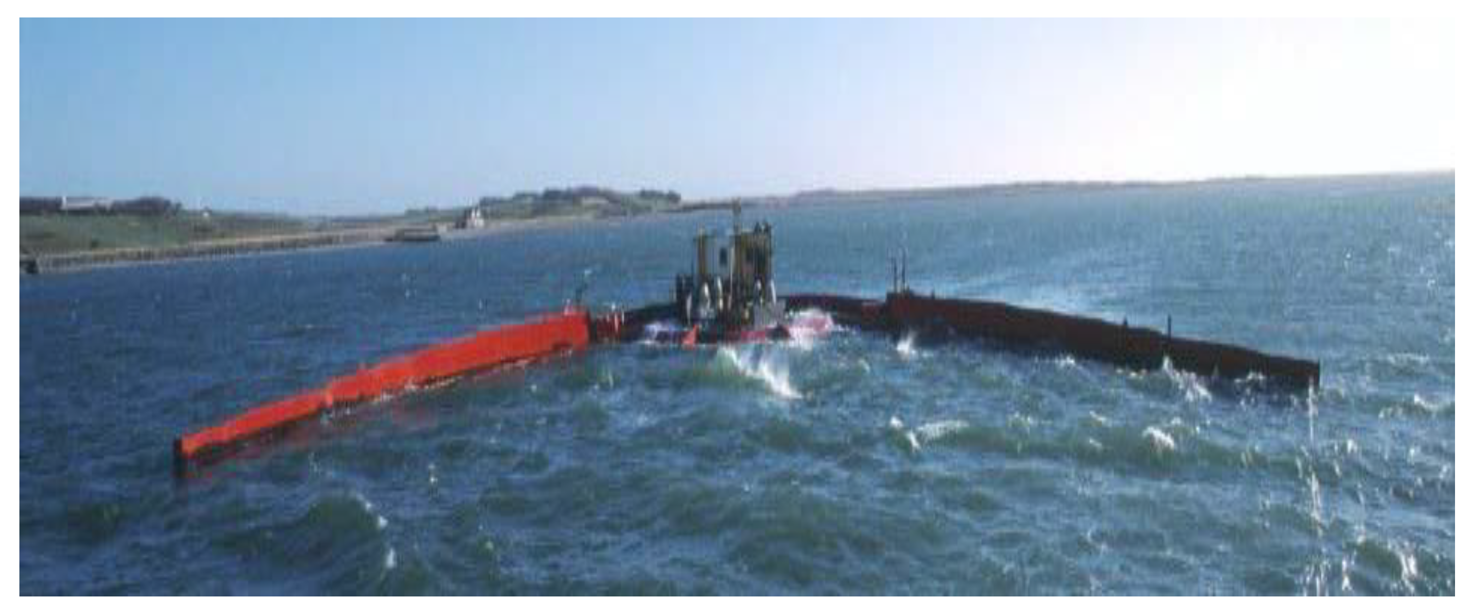
Submerged pressure differential: In general, this device’s position is near the shore and anchored to a seabed [62]. They usually are submerged point absorbers fixed and located near shore [69] and are Comprised of one or more chambers that are air-filled in which the pressure fluctuates based on the incident wave phase (trough or crest). The changing pressure in the presence of deformable chambers results in a continuous airflow within the device, which is converted by air turbine into electricity. This concept is found in the Bombora WEC [70]. The air chamber for rigid structures consists of one constant and one rotating component where there is a variation for chamber volume due to the changing pressure. The moving component down and up motions transform into electricity by the linear generator; it is applied in Archimedes Wave Swing [71], as shown in Figure 4.
Overtopping: The overtopping mechanism consists of a water reservoir above the surface level of the ocean, which causes the water of the reservoir to transfer to the sea through the turbine structure. The overtopping earliest devices in Norway are the wave power tapered channel devices (Tapchan) [72]. They have a 350kW nominal power. Wave Dragon is another conventional device and is a floating device designed in Denmark [73], as shown in Figure 5. The design of the slope Seawave Cone Generator [74] is similar to the Wave Dragon. Wave Dragon is a universal application that uses as overtopping devices, and the Wave Dragon structure is shown in references [73,75]. Wave Dragon is a multiple MW plant of production with maximum power take-off performance and fast maintenance. Moreover, because of its large size, it is costly. Wave Dragon covers a vast region of the ocean and has an environmental impact.
2.2.2. Direction
The WECs, according to the wave propagation direction, are classified as follows:
Attenuator: Usually, the attenuator is a flexing device, mounted parallel with the direction of propagation of the wave. An attenuator works by absorbing the energy from their two arms’ relative motion when the wave moves through them. This device is also a floating-type device that acts in parallel with the path of the wave and drives the waves efficiently [62]. The Pelamis [79] is a typical example. Three Pelamis units formed the commercial world’s first wave-farm of Portugal’s coast in September 2008 [80], as shown in Figure 7.
Terminator: This device intercepts waves by standing perpendicular to a prevailing direction of the wave [82,83]. The device Salter’s Duck, invented by Dr. Stephen Salter at Edinburgh University in 1978, is probably the most known of this kind, as shown in Figure 8.
Point absorber: Point absorber has considerably smaller dimensions than a wavelength and can produce power independently of the direction of the wave propagation. The buoy can oscillate to one degree of freedom or more, as shown in Figure 9. A motion of the buoy damping extracts energy, and a generator converts it into electricity. A pitching type point absorber is the example of the Salter’s Duck [39]. Wave Star [84], FO3 [85], and Manchester Bobber [86] are heaving type multipoint absorber devices.
Quasi-point absorber: Presented by Hals and Falnes [87], quasi-point absorbers characterize axisymmetric WECs, which are unresponsive to the direction of wave (like point absorbers) but have fairly broad dimensions comparable to wavelengths (like terminators).
A summary of WECs based on orientation is shown in Figure 10.
2.2.3. Location
Wave energy converters are classified based on the location as offshore, nearshore, and onshore.
Offshore locations: A higher energy level of waves in deep water makes the offshore devices more impressive for the production of wave power [83]. Offshore devices, due to the severe climatic conditions, can sustain larger loads; however, they are much more challenging to deploy and operate.
Nearshore: These devices are referred significantly to as lower water in which converters are attached commonly to an ocean floor. The example of a nearshore type device is WaveRoller [88].
Onshore: Onshore devices are fixed on the shoreline, with the benefit of being easy to maintain and install. Furthermore, moorings of deep water are not required, and the risk of storm damage to onshore devices is minimal, but the wave regime is less efficient.
A summary of WECs based on location is shown in Figure 11.
2.2.4. Power Take-Off
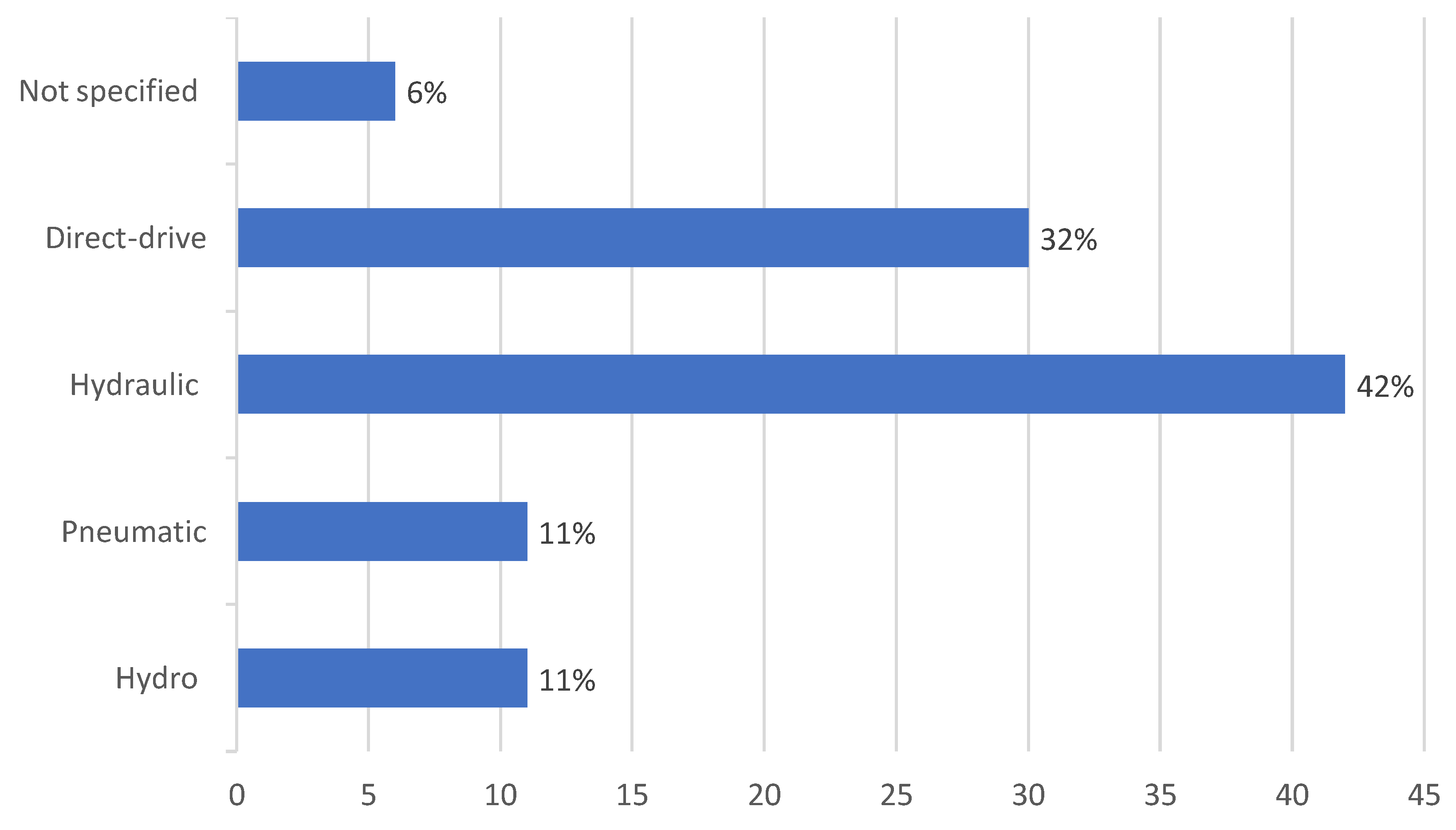
Typically, recognized power take-off (PTO) is the process where energy passed between the WEC and the waves, directly or subsequently, turns into a usable form [89]. The types of PTO include hydraulic, hydro, pneumatic, and direct-drive, and their efficiencies are shown in Table 3. The critical challenge of the development of PTO is that the machines must work at lower speeds and higher forces, whereas typical electrical generators are planned for low torque and higher speed motion. Although the efficiency of the hydraulic system is relatively low (see Table 3), it is most suitable for extracting wave energy, as seen in Figure 12 and further WEC examples with their (PTO) systems presented in Table 4.
Advancements and improvements continued in the wave energy sector, and a detailed assessment of power take-off is provided in reference [90].
Table 3.
Power take-off (PTO) systems’ efficiencies [91].
Table 3.
Power take-off (PTO) systems’ efficiencies [91].
| WEC Device Type | Efficiency % |
|---|---|
| Hydro | 85 |
| Pneumatic | 55 |
| Hydraulic | 65 |
| Direct mechanical drive | 90 |
| Direct electrical drive | 95 |
2.3. Power Production Analysis of WECs
Table 5 shows the systems-based power production analysis of WEC. The power values produced varies, which may well not be consistent and depend on the device’s size and location.
2.4. WEC Design Challenges
The design of an effectual and sturdy WEC faces several challenges.
(1) Some of the biggest challenges for WECs are the design and implementation because the technology is still in its infancy compared to other solar and wind [100,101,102,103] matured renewable technologies, despite numerous patents and prototypes published in several kinds of literature.
(2) The extraction of sea wave energy not only needs to be sustainable but efficient, because it may not be the sole accessible offshore clean energy option. In addition, to increase the WECs’ energy generation from the rate of current production, the power production cost needs to be decreased; at the same time, the efficiency of the system also needs to be improved as a whole.
(3) The WECs facing challenges vary from technological issues to operating and maintenance problems [104], extreme weather, and ocean salinity conditions in an extreme marine environment [105].
(4) The challenge is to extract energy from lower motion frequency and larger and variable displacement.
(5) The waves of the ocean change in periods and heights, and it is challenging to transform the waves’ kinetic energy into electric energy.
(6) The energy converters for ocean waves are typically located in extreme offshore climates. The appropriate mooring system, as well as the anti-corrosion perfect design, are dangerous.
(7) Wave energy converter optimized design is also a concern, as its design could impact the performance.
Some recent research [106,107] investigates the potential for the collaboration between the offshore wave power converters and wind turbines in a similar geographic region in order to maximize energy production and to minimize the costs of installation. It will provide a range of significant synergies and benefits, such as a reduction of the cost of installation integrating the electrical services, foundations, development and planning, operations, and maintenance expense.
3. Mooring System for WEC
WECs are essentially moored with cables and anchored to the ocean floor, generating electricity by using wave energy. As with most moored offshore structures on the ocean floor, a distinctive WEC mooring device may consist of three components: mooring lines, anchors, and connectors.
Based on their importance to WEC action, mooring systems are divided into three classes [108,109,110]: reactive, passive, and active.
Reactive mooring: The mooring mechanism is an essential part of a transformation system and is particularly appropriate as the PTO takes advantage of the associated motions between the seabed and WEC.
Passive mooring: When station holding is the primary aim of a mooring, the WEC’s power extraction from waves is unaffected.
Active mooring: The mooring system has an essential effect on the WEC’s power extraction and dynamic response, additional to offering station keeping.
3.1. Mooring Materials
Synthetic fiber rope, chain, and wire rope are three primary types of mooring lines used for offshore structures that may be used in WECs [111,112,113]. A comparison of various materials of the mooring line is provided by Harnois [114]. The material preference will affect factors, including the elastic stiffness, inertia, and mooring line damping. Chains are resistant to abrasion and offer decent catenary stiffness. However, some WECs cannot find the chain restraining stiffness appropriate. They can hinder the motion of oscillation needed to transfer energy. In addition to high costs, it is difficult to maintain a catenary line, since the chain embedded into the seabed is exceedingly long for much of a service period.
Synthetic ropes become beneficial along with their buoyancy properties, which can reduce the impact of mooring weight and are ideal options for applications in deep water [115]. Synthetic ropes such as polyester, High Modulus Polyethlene (HMPE), aramid, and nylon are typically used with mooring lines. A detailed review of the evaluation of several synthetic ropes for ocean renewable energy can be found in reference [116], in which it is confirmed that nylon and polyester are the appropriate materials for the compliant mooring structures.
A summary of the materials of mooring lines is shown in Table 6. The table compared different mooring lines like a chain, synthetic ropes, and wire ropes. The importance of a line’s features relies on the configuration of a mooring.
Anchors are like terminals that pass the entire forces of the system to the seafloor. The primary considerations for the anchor should be the capability of withstanding high horizontal and vertical (some cases) loads in certain seabed forms, soft to hard, and, further, be readily installable and cost-effective [114]. The mooring structures, in general, are subjected to strongly cyclic, nonlinear loading conditions, primarily caused by incident waves. There are several types of anchors available: drag anchor, dead weight, plate anchor, and pile anchor. Discussions are provided about anchors for wave energy converter systems in references [117,118]. The summary of different types of anchors is shown in Table 7. Numerous types of connectors are used in marine structures and WECs [111,119].
3.2. Mooring Configurations
Mooring systems may be divided appropriately for WECs into two primary configurations: single point mooring and spread mooring.
Spread mooring prevents the horizontal movement of the WEC and, thus, does not allow it to weather-vane. These mooring could be ideal for the non-directional energy converters. Single point mooring enables weather-vaning for a WEC [120,121]. Configurations of moorings are also categorized as slack/catenary and taut mooring. Taut mooring depends on whether cables are tightly stretched under pretension, and catenary/slack mooring depends on whether the cables hang slack. If the mooring system’s impact on the WEC’s vertical motion is to be reduced, the upper portion of the mooring cables must remain as horizontal as possible and connected directly to the WEC. In this condition, a buoy is connected horizontally to a WEC and anchored to the bottom of the sea. When mooring system compliance has to be improved, then the mooring lines must be attached with clump weights and subsurface buoys.
There are many subtypes of mooring systems, so it is hard to identify which is better without taking into account the safety, type, location, and cost of the WEC [122,123]. However, in spread mooring, Catenary Anchor Leg Mooring (CALM) appears to be more accessible, and in single point mooring (SPM), Single Anchor Leg Mooring (SALM) appears to be more prominent in realistic projects [117,124]. The summaries of mooring lines and anchors are shown in Table 6 and Table 7, respectively.
3.3. Mooring Requirements
In order to achieve a reasonable mooring of floating WECs, several designs and materials are proposed. It must be built as an essential part of the complete structure, which contributes to the efficiency of power extraction [125,126,127]. Nevertheless, the list for mooring requirements is lengthy and complicated, and it is not an easy task. A summary of primary design criteria for WECs’ mooring systems (collated mainly from Harnois [114], Fitzgerald [128], and Harris et al. [115]) is as follows:
(1) The moorings have to keep the system to a specified tolerance on the station. For WECs, the distance to adjacent machines in such an array or maximal offset permitted by the electrical power cable usually determines this.
(2) To mitigate the forces exerted on to the system itself, anchors and mooring lines must be appropriately compliant with the environmental loads.
(3) Under load criteria from classification rules [129], the moorings should remain intact, under ultimate, accident, and fatigue limit states.
(4) The mooring system’s horizontal footprint should be lessened for purposes of array performance.
(5) Conditions of slack-snap must be avoided.
(6) In arrays, feasible inter-moorings should require removal for the operation and repair of the individual system without disrupting neighboring devices.
(7) Moorings must not be harmful to power absorption under operating conditions.
(8) The mooring system installation should be decided to make it as simple as practicable. Inspection, repair, and possible removal of components of the mooring must be required within a standard weather timeframe.
(9) The design should consider marine growth, corrosion, and longer-term aging.
(10) It should be adequate to include the tidal scope at the position of installation.
Consequently, the design of a mooring is a crucial part of the project of a WEC because of wind, waves, and current; the structures are usually considered for use in regions with challenging environmental loads. Existing offshore guidelines, such as the DNV-OS-E301 [129], resolve these survivability challenges.
4. Modeling Approaches for WECs
The dynamic behavior of floating structures and waves, whether offshore platforms or ships, is usually modeled with a linear potential theory that is clearly illustrated in references [130,131]. These structures’ requirement to include small movements fits well with the small movement supposition of the linear potential theory. In addition to its clarity and reliable performance, the linear potential theory is often admired for the prospect of using it in simulations of time or frequency domains. As floating structures, it can be probable that linear potential theory could be used for modeling of floating WECs. For some, this may be valid, but others depend on large resonant motions’ amplitude to harvest energy and the linear potential theory’s small motion supposition does not apply.
More suitable approaches for these kinds of devices will be computational fluid dynamics (CFD) as in reference [132] or nonlinear potential theory as in reference [133]. CFD simulations are increasingly computationally affordable, as stated in the study in reference [134], and are becoming highly competitive with physical models. Nevertheless, both the simple nonlinear theory of potential and CFD are still challenging for useful engineering purposes. The most popular chosen method for applications of wave energy in CFD has been the use of totally nonlinear simulations of Reynolds-averaged Navier–Stokes (RANS) along with the method of the volume of fluid (VOF) for the interface of air–water [135].
The benefit of ocean basin experiments is that under managed environmental conditions they allow a thorough study of the system of WEC responses and can also be updated regularly. For different purposes, multiple ocean basin experiments of the systems of WECs have been performed, such as design evidence, power efficiency evaluation, analysis of hydrodynamic response, parametric analysis, and measurements of mooring and structural forces. Implementing a WEC model relies on simulation and numerical modeling because it offers the versatility to evaluate at a comparatively low cost with a wide range of WEC design choices. In order to evaluate scale results, Dai et al. [136] validated a computational model of the fixed OWC against physical experimental testing. When measurement variance was included, deviations up to 15 percent were reported while analyzing the amplitude operators’ (RAOs’) response and the power captured between numerical and experimental performance. Xu et al. [137] conducted a numerical and physical experimental analysis of the type of WEC as a floating point-absorber. Independent experimental research campaigns were undertaken in separate test facilities and with varying sizes under both survival and operational conditions. Windt et al. [138] verify the Wavestar WEC 1/5th NWT scale model for the output of power evaluation, detecting inconsistencies between numerical and physical results for the body motion, surface elevation, force of power take-off, and hull pressure. It is emphasized that the validity of a physical complex system needs extensive knowledge about device features in the computational model for the formulation’s assumptions.
In Table 8, numerous computational design techniques and experimental methods have been mentioned.
Consequently, the simulations of the floating WECs still need to rely on the linear potential theory. Time-domain simulations were performed to integrate nonlinear adverse effects with the aid of the methods of convolution like van Oortmerssen [154] or Cummins [155]. However, as Mårtensson and Bergdahl [156] had already recognized in 1995, floating WECs need specific methods to design.
5. Design of Mooring System
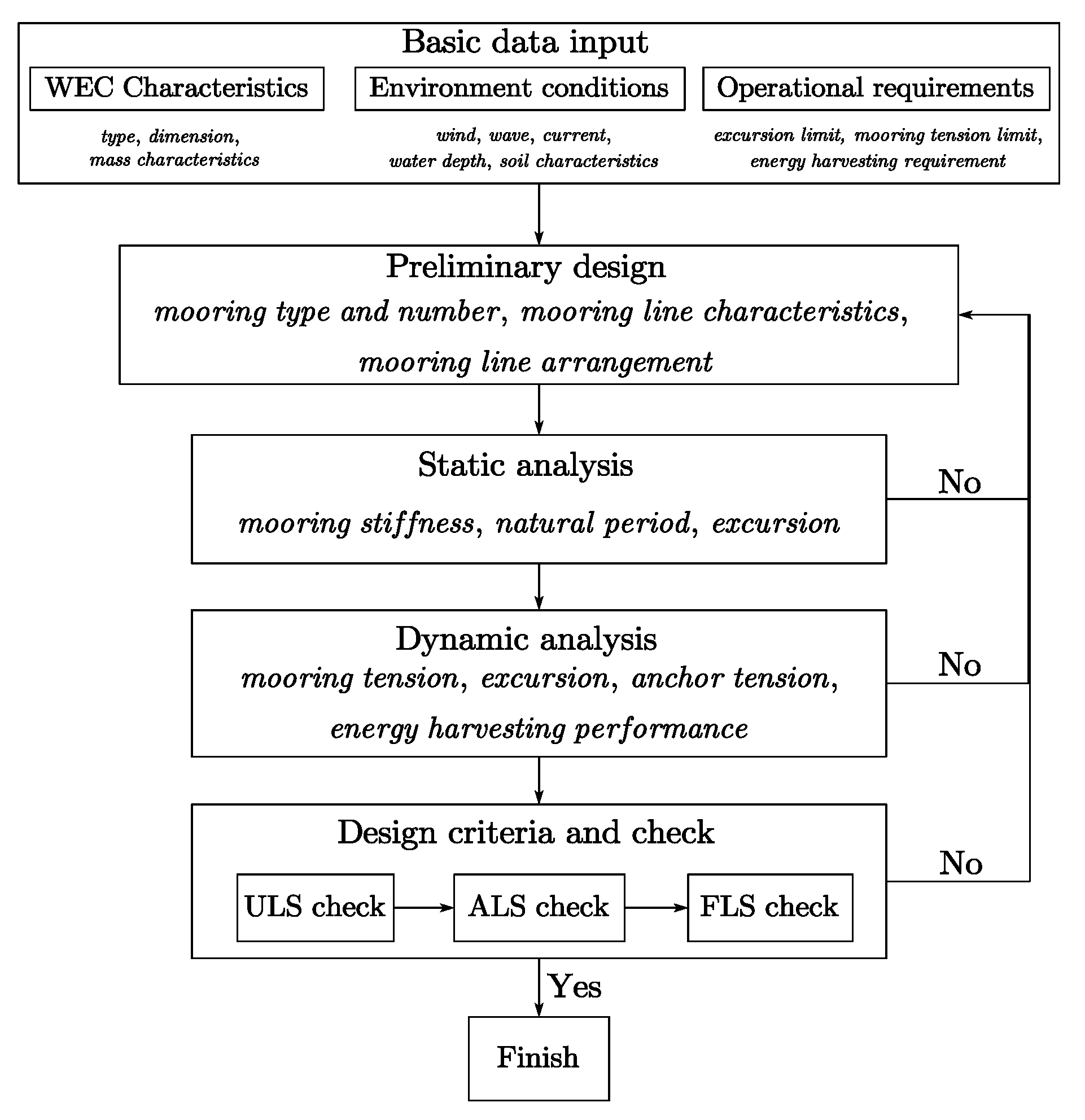
The mooring system design of WECs is a complex comprehensive system design, including design specifications; design sea states; structural characterization; mooring system data; selection of calculation and analysis methods; analysis, comparison, and verification of results; etc. The overall design flow chart is shown in Figure 13.
5.1. Mooring Design Considerations and Standards
The design contemplation for mooring structures comprises design loads, design criteria, design life, maintenance, and operation. The criteria of the design are specified concerning limit states like the ultimate limit state (ULS), accidental limit state (ALS), and fatigue limit state (FLS). Offshore design standard [157] describes these limit states as follows.
The ultimate limit state must assure that the independent mooring cables have enough strength to survive the load impacts caused by severe environmental behavior.
Accidental limit states assure that a mooring mechanism has enough ability to tolerate the collapse of the one mooring cable.
Fatigue limit states assure that the independent mooring cables have enough ability to survive cyclic loading.
The evaluation of a mooring structure is carried out by these kinds of three types of limit states. The design of the mooring cables for a permanent mooring should address all these three types of limit states [157]. The evaluation of the mooring structure consists primarily of two categorizations of the environmental conditions: the maximum operational and maximum design conditions.
The maximum design condition is determined by the conjunction of wind, current, and waves for the design of mooring structures. This condition is characterized as an intense conjunction of the waves, wind, and currents that cause excessive loads within the design environment [158]. The environmental loads are stated as wave height, wave period, wave spectrum, wind direction, wind speed, the function of wind spectrum, current direction, the current speed of surface, and current profile over the depth [157].
The maximum operational condition is described as a conjunction of wind, currents, and waves under which the device is capable of continuous operation, for example, drilling, offloading, or sustaining a gangway connection. This condition does not surpass the overall specification limit [158].
There is a range of certified companies globally in order to guarantee the offshore structures’ safe and practical design. The structure can be accredited and installed in the preferred destination by meeting the requirements of these companies. All these specifications are defined in several design guidelines that cover the methodology of analysis, safety factors, and specifications for materials. Table 9 provides the design standards documents for the mooring of WECs.
5.2. Analysis Model Types
Mathematically explaining the mooring system’s behavior with associations among parameters, variables, and environmental inputs may be applied with various types of models, differing in complexity. These different types of models can be categorized as static, dynamic, or quasi-static. Static models only recognize constant loads, including buoyancy, gravity, varying non-time current and wind, and mean forces of wave drift. A static analysis considers the equilibrium between the means environmental or constant loads and the mooring lines restoring force upon on a WEC. A quasi-static technique suggests that the system’s motion is continuous and linear among two static locations over a particular time phase in which the device loads are considered to be constant [178]. This approach lacks dynamic effects upon the mooring system, ignoring the system’s motion reliance on damping, fluid acceleration, and mass [179]. In general, the petroleum and gas industry mooring systems are mostly modeled using a quasi-static technique, because of their large structures and correlating inadequate responses with low velocity.
The structures are usually of lesser masses, in the market of WEC, so there may be an acceptance or even a need for higher displacements. Thus, a more distinctive response with more significant velocity, but lower loads, is generally reported; usually, the quasi-static technique ignores all of the dynamic effects from fluids, mass, and damping and considers just horizontal displacements, whereas dynamic analysis resolves motion’s equation across all of the degrees of the freedom and incorporates all of the dynamic effects [180].
Considerable non-linearities into the mooring system are present that must be adequately modeled by a software program. Non-linearities comprise, for example, nonlinear lines stretching, geometry changes, fluid effects, and the bottom effects. When resolving the motion equations, a time or frequency domain approach can be used. In the approach of the frequency domain, the series of linear motion equations handle the motions, measure, and integrate the values of the statistical peak for various motion inputs. The frequency domain demands that all of the non-linearities must be linearized. This linearization is inappropriate in the approach of a time domain, where the problem can be solved by direct mathematical integration. Therefore, the analysis of a time domain also includes time history of line tensions and WEC displacements.
Two different approaches could be used, uncoupled or coupled, when resolving the motion’s equation [1]. In the method of uncoupled, initially, the motions are resolved by ignoring the mooring lines’ effect after that WEC’s fairlead motion then is fed it into the cable, and tensions manage to be solved throughout the mooring lines. In the coupled method, the total equations of the system both for mooring lines and WECs are solved simultaneously. In addition, to accurately model the mooring line’s effects on WEC motions as well as the mooring system’s full nonlinear actions, design guidelines specify that the coupled method must be adopted. Comparably, a simulation of the time domain with all of the non-linearities and the dynamic effects is required for this.
5.3. Research Status
The mooring system must be designed to not negatively impact the WEC’s efficiency by lowering mooring loads and motions behaviors. In addition, the mooring system costs must also be taken into account. The research status is described as follows.
5.3.1. Mooring Design Concept
Fitzgerald and Bergdahl [181] and Martinelli et al. [27] describe in-depth many essential parts of WEC mooring design. The authors concluded from the findings of the study by reference [181] that the usage of the synthetic cable through more significant elasticity can significantly reduce the total load of the structure. Thomsen et al. [108] assess the existing state of mooring system design with a variety of Danish WECs, including a clear description of the mooring design approaches and assessments.
The design of mooring for WECs is available in reference [182], and the probable WEC design requirements can be seen in reference [183]. The evaluation of mooring structures in Denmark for large WECs was researched in references [184,185,186], where the expenses of the numerous mooring structures have been approximately measured. A comprehensive explanation of the cost expenditures of mooring structures for larger WECs is discussed in reference [187].
5.3.2. Static Approach for Initial Mooring Design
Monarcha and Fonesca [188] propose an analytically static approach for the initial design of multi-line mooring for offshore floating structures. Fonesca et al. [189] firstly proposed a static analysis to determine possible mooring designs, and then further refined and improved them with dynamic analysis. For preliminary design, Johanning et al. [179] suggest that a static approach should be used to measure the maximum stress and tensions on the mooring components of the WEC due to severe environmental factors by which initial dimensions of the components of material can be determined for more analysis. The static analysis is incredibly simple, producing results in fewer seconds, whereas the dynamic analysis may take hours to produce relevant results, relying on the complexities of the system [189].
5.3.3. Dynamic Approach for Mooring Design
A dynamic analysis is needed to determine the maximum tension within a mooring system. Models of dynamic mooring cables are different from models of quasi-static since they can accommodate the effects of drag, inertia, and internal damping. Dynamic mooring cables, in particular, transmit both transverse and longitudinal vibrations. In models of quasi-static such vibrations are neglected. The mooring initially was built using a quasi-static modeling process, and dynamic simulations then followed. Then, the calculations of dynamic may be performed in the frequency domain to enable the execution of several cases, from which some crucial cases must be run in the time domain.
Brown and Mavrakos et al. [190] compared experimental data with the outcomes from many frequency and time domain methodologies. Differences in the measurement of the mooring damping were found. Liu [191] focused on the response of the dynamic analysis of moored floating structures and extreme value difficulties. The standard method of calculating the extreme tensions of the mooring line is to run multiple time-domain simulations that are computationally costly. Consequently, Liu [191] suggests that in order to estimate the tension of extreme mooring lines, just fewer simulations, and the extreme theory value therein, are needed. Liu determines the predicted extreme tensions of mooring cable, utilizing statistical techniques, on time-domain nonlinear simulations [192], and afterward extreme responses through combined Low Frequency-Wave Frequency (LF–WF) excitation for floating moored platforms [193]. Masciola et al. [194] studied the different theories of dynamic line modeling, which are currently being used in offshore simulation applications. The benefits of each model were assessed, and even though every model had merit, the lumped mass (LM) model was selected for inclusion in the mooring analysis program (MAP). Bergdahl [195] addresses the number of environmental factors that should be considered when developing a mooring system for WECs. An overview of how to build a mooring system with the help of static, dynamic, and quasi-static models is present in various design stages.
5.3.4. Optimization Approach for Mooring Design
Design optimization of mooring systems of offshore floating structures is a challenging task, partly because of the large number of design variables, complicated design constraints, nonlinear system behavior, and time-consuming numerical simulations.
Shafieefar and Rezvani [196] introduced the optimization of the floating platform mooring design, which reduces platform responses. A genetic algorithm (GA) had been applied, and they explain precisely how to create a GA code to solve mooring configuration optimization problems. The optimized model of moorings was tested for varying environmental factors, and conclusions were presented, with the time expected to run. Pillai et al. [197] described a method for optimizing mooring structures in renewable offshore energy systems. This methodology examines the positioning of the anchors along with the length, diameter, and material of the mooring cables to reduce the tension in the cables, mooring system costs, and the risk of fatigue into the system at the same time—the multi-objective strategy used for these objectives instead of limiting to a single target optimization problem. Pillai et al. [198] proposed a new method for multi-objective optimization of mooring systems that used a randomized forest-based surrogate methodology combined with the genetic algorithm—minimizing mooring system costs as well as cumulative fatigue risk. Li et al. [199] introduced an integrated methodology for optimizing mooring system design. The methodology incorporates screening analysis, time-domain simulations, experiment design, and metamodel-based procedures of optimization, where the Kriging metamodels are used as surrogates for simulated time-domain responses. The proposed approach also refers to the design of the optimization of other ocean structures. Wang [200] provides an optimization analysis on the design of offshore mooring structures, describing that the usage of mooring models with the approach of numerical optimization to provide software that helps in the design and to optimize offshore mooring structures.
5.3.5. Experimental Approach for Mooring Design
Sirigu et al. [201] performed an experimental study of the hydrodynamic efficiency of a floater and compared the outcomes of numerical codes. Exploring the various effects of the forces of moorings on the dynamics of a floater, two separate configurations of the mooring were evaluated, and the variations between experimental and numerical findings and the nonlinearities effect on hydrodynamic efficiency were concluded. Sirigu et al. [152] proposed an experimental strategy on an Inertial Sea Wave Energy Converter (ISWEC) scaled prototype 1:20 based on the effect of the mooring configuration on loads in extreme conditions of the wave. The goal was to find the solution of mooring that could ensure the proper operation of the system and the severe sea conditions for load carrying. Yang et al. [202] presented a numerical and experimental analysis of a taut-moored WEC device with a kind of point-absorber WEC. Two realistic models were designed and tested in the 1:20 and 1:36 scale models and motions of the WEC buoy were validated. Yang et al. [203] in another study, validated calculations of the mooring force for the same model [202]. An experimental study on a floating 1:25 scaled OWC model was given in reference [204]. Two kinds of mooring materials considered, nylon rope and iron chain, were used to study their effect on the mooring lines’ tensions. It concluded that nylon rope could introduce substantially greater surge motion; no shock loading was found in the measured wave conditions for the iron chain configuration. An experimentally investigated taut-mooring system behavior for floating WEC is available in reference [205]. An experimental analysis of advantages and effects that various mooring principles of point absorbers might have is available in reference [206].
Table 10 provides some further research publications of different types of mooring system design for WECs.
5.4. Software
There is a wide range of software programs for the analysis of mooring floating structures, for example, quasi-static for ports design and offshore petroleum and gas structures, as well as other dynamic modeling tools. For WECs’ moorings, only dynamic software is required. The list of some suitable software options is in Table 11.
5.5. Mooring Design Challenge
The mooring system is a core component in the economic viability of wave energy projects. WEC moorings need to meet the same requirements as the other offshore systems. Designing and analyzing mooring systems poses many challenges, some obvious and some subtler. Sections below illustrate some of the main issues that require attention.
5.5.1. Metocean
Firstly, it is not easy to collect quality data within the timeframe needed for the site. Early data collection planning is usually cost-effective and significantly reduces needless design conservativism. Even when there are useful data available, suitable criteria development for floating structures still are challenging.
In order to define the design requirements and assess extreme environmental conditions to be evaluated, a thorough assessment of the dynamic response of the system is necessary. WECs are usually mounted in depths of water <100 m [42]; therefore, the wave height design is technically a significant component. For that, loads of ocean waves and tidal fluctuations at the site of installation should be incorporated.
The specialist of metocean and the mooring need to collaborate to match the design requirements based on the responses. A permanently designed system, for example, in the North Sea, must be planned to withstand the highest wave predicted in the hundred years and leading to waves over 20 m higher in places [129].
The concept of extreme and related environments can be highly valuable, as well as can have a considerable impact on design. For example, cases of an extreme environment may be described as a return period of 100-year condition. The environment associated may be the 90 percent non-exceedances current and wave condition that must be applied to the design simultaneously. To accurately determine an associated environment, the specialist of metocean needs to consider the responsiveness of the dynamic response of a system in both the direction and magnitude of an associated environment.
5.5.2. Responses
For the response criteria for WEC systems, engineers are confronted with complexity relating to the maximum appropriate mooring configuration as well as long-term durability of mooring components. The concepts of mooring configuration for WECs’ progress need analysis from theoretical and experimental studies. The moorings would either need sufficient flexibility to withstand significant displacements or even have adequate capacity to resist their hydrodynamic loads for controlling the motions of the structure. With regards to the retaining flexibility of station, moorings play a significant role in several WECs’ designs as they affect the amplitude of the hydrodynamic action.
When designing the mooring systems for WECs, the challenging issues are the environmental inputs’ broad range frequency and responses of the mooring system. The time ranges in which physical phenomena arise within the mooring structure cover: static loading that varies according to the tidal influences, WEC Low-frequency motions due to the 2nd order wave drift, WEC Wave-frequency motions, and High-frequency loading that propagates and acts on the line. Although these effects arise at various frequencies, every one of them may be handled independently by one modeling approach to enable the modeling tractable.
5.5.3. Strength and Fatigue
The role of designing a good mooring system for the conditions of design loading may be minimized to choosing the best combination of material strength and compliance. The harsh offshore environment presents a mooring design challenge in established industries like the oil and gas industry. Thus, the design of mooring is closely related to the output of power production [128]; that is why moorings must be considered in a quite early design stage and development of the WEC concept.
Evaluations of failures of the mooring line reveal that the majority of problems arise during the operation of the initial ten years, with the bulk of failures happening in the initial five years [241,242]. Another analysis of incidents of mooring [243], based around 2000 to 2013 on the Norwegian continental shelf, reveals that 54% of the 26 marine accidents reported were owing to breakage of the mooring line. The research highlights the most likely technological reasons for cable failures: line overloads due to snap loads or severe weather conditions, chain fatigue fractures, and fiber lines impaired.
In several areas of the globe, commonly, mooring systems for shallow water are designed to satisfy the requirements of strength and usually meet the fatigue requirements, but it is no longer implemented in the deepwater system. The pretensions for the systems of deepwater are usually higher, and the mooring system of a taut nature results in dynamic tensions, which are considerably higher in normal wave conditions. Fatigue plays a dominant role in deepwater moorings, and it is particularly true concerning the chain of mooring. The prevalent utilization of a studless chain with a shorter lifetime of fatigue, therefore, made the issue more serious.
Modern designs of mooring typically use mooring line groups to keep providing redundancy as in case of a cable failure. The desire for mooring lines’ pretension accuracy is strengthened as tension inequalities in neighboring mooring lines results in a significant reduction in fatigue life on the group’s highly loaded line. Sensitivity reviews are highly recommended for realistic deployment tolerances, mainly when the margins of design are small. The sensitivity of pretension fatigue damage stems from the truth that the magnitude of dynamic stress directly increases with the pretension, as well as the damage to fatigue is nearly proportional to the dynamic stress range cube. Thus, pretension imbalances within a group can contribute to reduced performance of fatigue.
5.5.4. Snap Failure
Snap loads appear in cables due to many reasons but are most generally correlated with the slack of cable and the sharp snap that happens as the cable is retightened. In the wave energy research projects [114,244], there are incidents of snap loading that cause severe damage. DNV-GL [129] suggests that conditions of slack-snap must be kept low or avoided by the probability of minimum occurrence. An effective solution to handle snap loads is to analyze them with software that accurately estimates snap duration, magnitude, and occurrence. For appropriate mooring structures of WECs, it would be useful to anticipate and minimize the snap loads in the process of design iteration.
5.5.5. Installation
It is crucial to making sure that the mooring system introduces zero or least twist during hook-up in the stage of final or pre-installation for the long-term mooring integrity. The existence of a wire rope twist may result in action to bird-caging as well as premature failure. The existence of a mooring chain twist can significantly reduce performance in terms of fatigue and strength. Preferably the mooring cables at a hook-up should be twist-free. Additional precautions are needed to prevent the implementation of twist during deployment. A few installation times may need to be invested in removing twist. This stage enhances the time of installation and, thus, the cost, but for the mooring system, optimal performance is essential.
In a mooring structure, the appropriate degree of twist is challenging, and the long-term mooring chain and mooring wire behavior in the existence of differing twist levels cannot be well predicted. There are analytical tools that may be utilized as rough guidance but may not be benchmarked. Reliable tension measuring devices are needed during deployment. Chain separation angle measurement worked practically well for catenary systems of shallow water. For taut systems, the angle resolution measurement maybe not sufficient.
6. Conclusions
Many kinds of research on wave energy are presently ongoing across the globe, especially in China, the United States, and Europe. Advances have been made in experimental research, theoretical, and model design of the prototypes of WEC moorings. The advances in the technologies for prospective characterizations of wave resources have been quite motivating as powerful computer tools and algorithms are now accessible to forecast and to simulate wave environments with spatial resolutions and finer temporal accuracy. The use of wide-scale experiments is recently demonstrated by success in numerical simulations of CFD while integrating dynamic associations between the sea waves and WEC. The use of simulations and experimental experiments in the emerging wave energy sector can contribute to higher performance. Because of the universal need to analyze, optimize, and design moorings for offshore structures, the mathematical simulation for mooring systems of WECs needs to borrow several existing approaches from the other fields of offshore engineering. This paper also provides information related to the suitability of commercial modeling tools for mooring designs of WECs. Most of the software offers some similar features, although some software provides more advanced methods.
Hybrid mooring, consisting of clump weights, buoys, and mooring lines, is an appealing option of station keeping for WECs and demonstrates excellent results in reducing mooring loads and absorbing environmental energy. Due to the capability to reduce environmental loads, it is recommended that the SPM method must be implemented in large measurements of WECs, and indeed the SALM is a suitable option for floating WECs. Spread mooring works well, in the station keeping of small structures of WECs. For most situations, because of its wide footprint, high stiffness, and significant expenses, the catenary mooring cables are appropriate for shallow water WEC applications. Fiber ropes, particularly for materials that are highly compliant, for example, nylon or other elastic ropes, demonstrate significant benefits in the use of a WEC mooring. However, synthetic rope fatigue and wear issues must be considered.
The mooring system must be designed to not negatively impact the WEC’s efficiency by lowering the mooring loads and motion behaviors as much as possible. Additionally, the mooring system costs must also be taken into account, and the energy levelized cost decreases as the efficiency of wave power increases. Moreover, other factors, like water depth, may also be responsible for costs. In comparison to floating structures, the water level would undoubtedly impact fixed structures. If the range of WECs increases further offshore, then the cost of transmission will rise. Transmission expenses can be minimized by sharing deployed facilities in the offshore region, such as wind turbines, if accessible.
Author Contributions
Conceptualization, D.Q. and R.H.; methodology, J.Y. and B.L.; writing—original draft preparation, D.Q. and R.H.; writing—review and editing, J.Y. and D.N. All authors have read and agreed to the published version of the manuscript.
Funding
This work was funded by the National Key R&D Program of China [Grant NO. 2018YFB1501905], the Fundamental Research Funds for the Central Universities.
Conflicts of Interest
The authors declare no conflict of interest.
References
- Clément, A.; McCullen, P.; Falcão, A.; Fiorentino, A.; Gardner, F.; Hammarlund, K.; Lemonis, G.; Lewis, T.; Nielsen, K.; Petroncini, S.; et al. Wave energy in Europe: Current status and perspectives. Renew. Sustain. Energy Rev. 2002, 6, 405–431. [Google Scholar] [CrossRef]
- Thorpe, T.W. A Brief Review of Wave Energy; Harwell Laboratory, Energy Technology Support Unit: London, UK, 1999. [Google Scholar]
- Ilyas, A.; Kashif, S.A.R.; Saqib, M.A.; Asad, M.M. Wave electrical energy systems: Implementation, challenges and environmental issues. Renew. Sustain. Energy Rev. 2014, 40, 260–268. [Google Scholar] [CrossRef]
- Mork, G.; Barstow, S.; Kabuth, A.; Pontes, M.T. Assessing the Global Wave Energy Potential. In Proceedings of the OMAE2010 29th International Conference on Ocean, Offshore Mechanics and Arctic Engineering, Shanghai, China, 6–11 June 2010. [Google Scholar]
- Izadparast, A.H.; Niedzwecki, J.M. Estimating the potential of ocean wave power resources. Ocean Eng. 2011, 38, 177–185. [Google Scholar] [CrossRef]
- Mollison, D. Hydrodynamics of Ocean Wave-Energy Utilization; Springer: Berlin, Germany, 1986; pp. 133–156. [Google Scholar]
- Lenee-Bluhm, P.; Paasch, R.; Özkan-Haller, H.T. Characterizing the wave energy resource of the US Pacific Northwest. Renew. Energy 2011, 36, 2106–2119. [Google Scholar] [CrossRef]
- Iglesias, G.; López, M.; Carballo, R.; Castro, A.; Fraguela, J.A.; Frigaard, P. Wave energy potential in Galicia (NW Spain). Renew. Energy 2009, 34, 2323–2333. [Google Scholar] [CrossRef]
- Citiroglu, H.K.; Okur, A. An approach to wave energy converter applications in Eregli on the Western Black Sea Coast of Turkey. Appl. Energy 2014, 135, 738–747. [Google Scholar] [CrossRef]
- Haces-Fernandez, F. Investigation on the Possibility of Extracting Wave Energy from the Texas Coast. Master’s Thesis, Texas A&M University Kingsville, Kingsville, TX, USA, 2014. [Google Scholar]
- IEA–International Energy Agency. Available online: https://www.iea.org/ (accessed on 20 July 2020).
- Cruz, J. Ocean Wave Energy Current Status and Future Perspectives; Springer: Berlin, Germany, 2008. [Google Scholar]
- IRENA–International Renewable Energy Agency. Available online: https://www.irena.org/ (accessed on 20 July 2020).
- Jones, N. The Outlook for Energy: A View to 2040; Technical Report by Exxon Mobil Corporation: Spring, TX, USA, 2015. [Google Scholar]
- Annual Report Ocean Energy Systems. Available online: https://report2016.ocean-energy-systems.org/ (accessed on 20 July 2020).
- Jacobson, P.T.; Hagerman, G.; Scott, G. Mapping and Assessment of the United States Ocean Wave Energy Resource; Electric Power Research Institute: Palo Alto, CA, USA, 2011. [Google Scholar]
- Lawrence, J.; Kofoed-Hansen, H.; Chevalier, C. High-Resolution Metocean Modelling at EMEC’s (UK) Marine Energy Test Sites. In Proceedings of the 8th European Wave and Tidal Energy Conference, Uppsala, Sweden, 7–10 September 2009. [Google Scholar]
- Neary, V.S.; Lawson, M.; Previsic, M.; Copping, A.; Hallett, K.C.; LaBonte, A.; Murray, D. Methodology for Design and Economic Analysis of Marine Energy Conversion (MEC) Technologies; Sandia National Lab. (SNL-NM): Albuquerque, NM, USA, 2014. [Google Scholar]
- Cada, G.; Ahlgrimm, J.; Bahleda, M.; Bigford, T.; Stavrakas, S.D.; Hall, D.; Moursund, R.; Sale, M. Potential impacts of hydrokinetic and wave energy conversion technologies on aquatic environments. Fisheries 2007, 32, 174–181. [Google Scholar] [CrossRef]
- Brekken, T.K.; von Jouanne, A.; Han, H.Y. Ocean wave energy overview and research at Oregon State University. In Proceedings of the Power Electronics and Machines in Wind Applications, Lincoln, NE, USA, 24–26 June 2009. [Google Scholar]
- Ocean Power Technologies. Available online: https://oceanpowertechnologies.com/new-homepage-alt/ (accessed on 20 July 2020).
- Whittaker, T.; Collier, D.; Folley, M.; Osterried, M.; Henry, A.; Crowley, M. The Development of Oyster A Shallow Water Surging Wave Energy Converter. In Proceedings of the 7th European Wave and Tidal Energy Conference, Porto, Portugal, 1 September 2007. [Google Scholar]
- Pelc, R.; Fujita, R.M. Renewable energy from the ocean. Mar. Policy 2002, 26, 471–479. [Google Scholar] [CrossRef]
- Czech, B.; Bauer, P. Wave energy converter concepts: Design challenges and classification. IEEE Ind. Electron. Mag. 2012, 6, 4–16. [Google Scholar] [CrossRef]
- Lehmann, M.; Karimpour, F.; Goudey, C.A.; Jacobson, P.T.; Alam, M.-R. Ocean wave energy in the United States: Current status and future perspectives. Renew. Sustain. Energy Rev. 2017, 74, 1300–1313. [Google Scholar] [CrossRef]
- Fitzgerald, J. Position Mooring of Wave Energy Converters. Ph.D. Thesis, Chalmers Univerisity of Technology, Gothenburg, Sweden, 2009. [Google Scholar]
- Martinelli, L.; Ruol, P.; Cortellazzo, G. On Mooring Design of Wave Energy Converters the Seabreath Application. In Proceedings of the 33rd International Conference Coastal Engineering, Padua, Italy, 1–6 July 2012. [Google Scholar]
- Fitzgerald, J.; Bergdahl, L. Including moorings in the assessment of a generic offshore wave energy converter: A frequency domain approach. Mar. Struct. 2008, 21, 23–46. [Google Scholar] [CrossRef]
- Webster, W.C. Mooring-induced damping. Ocean Eng. 1995, 22, 571–591. [Google Scholar] [CrossRef]
- IRENA. Wave Energy Technology Brief. 2014. Available online: www.irena.org (accessed on 21 July 2020).
- McCormick, M.E. Ocean Wave Energy Conversion; Courier Corporation: North Chelmsford, MA, USA, 1981. [Google Scholar]
- Ross, D. Power from the Waves; Oxford University Press: New York, NY, USA, 1995. [Google Scholar]
- Falnes, J. A review of wave-energy extraction. Mar. Struct. 2007, 20, 185–201. [Google Scholar] [CrossRef]
- Masuda, Y. An experience of wave power generator through tests and improvement. In Hydrodynamics of Ocean Wave-Energy Utilization; Springer: Berlin/Heidelberg, Germany, 1986; pp. 445–452. [Google Scholar]
- Masters, C.D.; Root, D.H.; Dietzman, W.D. Distribution and quantitative assessment of world crude-oil reserves and resources. In The Changing Carbon Cycle; Springer: New York, NY, USA, 1986; pp. 491–507. [Google Scholar]
- McGlade, C.; Ekins, P. The geographical distribution of fossil fuels unused when limiting global warming to 2 C. Nature 2015, 517, 187–190. [Google Scholar] [CrossRef]
- Previsic, M.; Moreno, A.; Bedard, R.; Polagye, B.; Collar, C.; Lockard, D.; Rocheleau, R. Hydrokinetic Energy In The United States—Resources, Challenges and Opportunities. In Proceedings of the 8th European Wave Tidal Energy Conference, Uppsala, Sweden, 7–10 September 2009. [Google Scholar]
- Grove-Palmer, C.O.J. Wave Energy in the United Kingdom: A Review of the Programme June 1975 to March 1982. In Proceedings of the 2nd International Symposium on Wave Energy Utilization, Trondheim, Norway, 22–24 June 1982. [Google Scholar]
- Salter, S.H. Wave power. Nature 1974, 249, 720–724. [Google Scholar] [CrossRef]
- Shaw, R. Wave Energy A Design Challenge; Ellis Horwood: Chichester, UK, 1982. [Google Scholar]
- Charlier, R.H.; Justus, J.R. Ocean Energies: Environmental, Economic and Technological Aspects of Alternative Power Sources; Elsevier: Amsterdam, The Netherlands, 1993. [Google Scholar]
- Cruz, J. Ocean Wave Energy Current Status and Future Prespectives; Springer: Berlin, Germany, 2007. [Google Scholar]
- Brooke, J. Wave Energy Conversion; Elsevier: Amsterdam, The Netherlands, 2003. [Google Scholar]
- WaveNet, Results from the Work of the European Thematic Network on Wave Energy. Available online: http://www.wave-energy.net/Main.htm (accessed on 21 July 2020).
- Salter, S.H. World Progress in Wave Energy—1988. Int. J. Ambient Energy 1989, 10, 3–24. [Google Scholar] [CrossRef]
- Thorpe, T.W. An Overview of Wave Energy Technologies: Status, Performance and Costs; Moving towards Commercial Viability: London, UK, 1999. [Google Scholar]
- Falcão, A.F.d.O. First-Generation Wave Power Plants Current Status and R&D Requirements. In Proceedings of the 22nd International Conference on Offshore Mechanics and Arctic Engineering, Cancun, Mexico, 8–13 June 2003. [Google Scholar]
- Murray, R. Review and Analysis of Ocean Energy Systems Development and Supporting Policies; Implementing Agreement on Ocean Energy Systems: Ireland, UK, 2006. [Google Scholar]
- Hagerman, G. Wave Energy Resource and Economic Assessment for the State of Hawaii; SEASUN Power System: Alexandria, VA, USA, 1992. [Google Scholar]
- Magagna, D.; Uihlein, A. Ocean energy development in Europe current status and future perspectives. Int. J. Mar. Energy 2015, 11, 84–104. [Google Scholar] [CrossRef]
- Merigaud, A.; Gilloteaux, J.-C.; Ringwood, J.V. A Nonlinear Extension for Linear Boundary Element Methods in Wave Energy Device Modelling. In Proceedings of the ASME 31st International Conference on Ocean Offshore and Arctic Engineering, Rio de Janeiro, Brazil, 1–6 July 2012. [Google Scholar]
- Antonio, F.D.O. Wave energy utilization: A review of the technologies. Renew. Sustain. Energy Rev. 2010, 14, 899–918. [Google Scholar]
- Falcão, A.F.O.; Henriques, J.C.C. Oscillating-water-column wave energy converters and air turbines: A review. Renew. Energy 2016, 85, 1391–1424. [Google Scholar] [CrossRef]
- Medina-Lopez, E.; Allsop, W.; Dimakopoulos, A.; Bruce, T. Conjectures on the Failure of the OWC Breakwater at Mutriku. In Proceedings of the Coastal Structures and Solutions to Coastal Disasters Joint Conference 2015, Boston, MA, USA, 9–11 September 2015. [Google Scholar]
- Bedard, R.; Hagerman, G. E2I EPRI Assessment Offshore Wave Energy Conversion Devices; Electricity Innovation Institute: Washington, DC, USA, 2004. [Google Scholar]
- Australian Renewable Energy Agency. Available online: https://arena.gov.au/ (accessed on 20 July 2020).
- Whittaker, T.J.T.; Beattie, W.; Folley, M.; Boake, C.; Wright, A.; Osterried, M.; Heath, T. The limpet wave power project—The first years of operation. Renew. Energy 2004, 1–8. [Google Scholar]
- Falcão, A.F.O. The Shoreline OWC Wave Power Plant at the Azores. In Proceedings of the 4th European Wave Energy Conference, Aalborg, Denmark, 4–6 December 2000. [Google Scholar]
- Lindroth, S.; Leijon, M. Offshore wave power measurements—A review. Renew. Sustain. Energy Rev. 2011, 15, 4274–4285. [Google Scholar] [CrossRef]
- Falcão, A.F.O.; Henriques, J.C.C.; Cândido, J.J. Dynamics and optimization of the OWC spar buoy wave energy converter. Renew. Energy 2012, 48, 369–381. [Google Scholar] [CrossRef]
- Masuda, Y.; Yamazaki, T.; Outa, Y.; McCormick, M. Study of Backward Bent Duct Buoy. In Proceedings of the OCEANS’87, Halifax, NS, Canada, 28 September–1 October 1987. [Google Scholar]
- European Marine Energy Centre. Available online: http://www.emec.org.uk/marine-energy/wave-devices/ (accessed on 20 July 2020).
- Wave developers European Marine Energy Centre. Available online: http://www.emec.org.uk/marine-energy/wave-developers/ (accessed on 20 July 2020).
- CorPower Ocean. Available online: https://www.corpowerocean.com/ (accessed on 20 July 2020).
- Ocean Power Technologies. Available online: https://oceanpowertechnologies.com/pb3-powerbuoy/ (accessed on 20 July 2020).
- Carnegie Clean Energy. Available online: https://www.carnegiece.com/technology/ (accessed on 20 July 2020).
- SEABASED. Available online: https://seabased.com/ (accessed on 20 July 2020).
- Babarit, A.; Hals, J.; Kurniawan, A.; Muliawan, M.; Moan, T.; Krokstad, J. The NumWEC Project: Numerical Estimation of Energy Delivery from a Selection of Wave Energy Converters; Final Report for Statkraft: Nantes, France, 2011. [Google Scholar]
- Polinder, H.; Damen, M.E.C.; Gardner, F. Design, modelling and test results of the AWS PM linear generator. Eur. Trans. Electr. Power 2005, 15, 245–256. [Google Scholar] [CrossRef]
- Algie, C.; Ryan, S.; Fleming, A. Predicted power performance of a submerged membrane pressure-differential wave energy converter. Int. J. Mar. Energy 2017, 20, 125–134. [Google Scholar] [CrossRef]
- Valério, D.; Beirão, P.; Da Costa, J.S. Optimisation of wave energy extraction with the archimedes wave swing. Ocean Eng. 2007, 34, 2330–2344. [Google Scholar] [CrossRef]
- Evans, D.V.; Falcao, A.F.O. Hydrodynamics of Ocean Wave-Energy Utilization; Springer: New York, NY, USA, 1985. [Google Scholar]
- Kofoed, J.P.; Frigaard, P.; Friis-Madsen, E.; Sørensen, H.C. Prototype testing of the wave energy converter wave dragon. Renew. Energy 2006, 31, 181–189. [Google Scholar] [CrossRef] [Green Version]
- Margheritini, L.; Vicinanza, D.; Frigaard, P. Hydraulic Characteristics of Seawave Slot-Cone Generator Pilot Plant at Kvitsøy (Norway). In Proceedings of the 7th European Wave Tidal Energy Conference, Porto, Portugal, 11–13 September 2007. [Google Scholar]
- Wave Dragon. Available online: http://www.wavedragon.net/ (accessed on 20 July 2020).
- Babarit, A. A database of capture width ratio of wave energy converters. Renew. Energy 2015, 80, 610–628. [Google Scholar] [CrossRef]
- Babarit, A.; Wendt, F.; Yu, Y.-H.; Weber, J. Investigation on the energy absorption performance of a fixed-bottom pressure-differential wave energy converter. Appl. Ocean Res. 2017, 65, 90–101. [Google Scholar] [CrossRef] [Green Version]
- International Renewable Energy Agency (IRENA). Ocean Energy: Technologies, Patents, Deployment Status and Outlook; IRENA: Abu Dhabi, UAE, 2014. [Google Scholar]
- Pizer, D.J.; Retzler, C.H.; Yemm, R.W. The OPD Pelamis Experimental and Numerical Results from the Hydrodynamic Work Program. In Proceedings of the 4th EWTEC European Wave Energy Conference, Aalborg, Denmark, 4–6 December 2000. [Google Scholar]
- Mueller, M.; Wallace, R. Enabling science and technology for marine renewable energy. Energy Policy 2008, 36, 4376–4382. [Google Scholar] [CrossRef]
- European Marine Energy Centre. Available online: http://www.emec.org.uk/about-us/wave-clients/pelamis-wave-power/ (accessed on 23 July 2020).
- López, I.; Andreu, J.; Ceballos, S.; De Alegría, I.M.; Kortabarria, I. Review of wave energy technologies and the necessary power-equipment. Renew. Sustain. Energy Rev. 2013, 27, 413–434. [Google Scholar] [CrossRef]
- Drew, B.; Plummer, A.R.; Sahinkaya, M.N. A Review of Wave Energy Converter Technology; Sage Publications Sage UK: London, UK, 2009. [Google Scholar]
- Bjerrum, A. The Wave Star Energy Concept. In Proceedings of the 2nd International Conference on Ocean Energy, Brest, France, 15–17 October 2008. [Google Scholar]
- Taghipour, R.; Moan, T. Efficient Frequency-Domain Analysis of Dynamic Response for the Multi-Body Wave Energy Converter in Multi-Directional Wave. In Proceedings of the 18th International Offshore and Polar Engineering Conference, Vancouver, BC, Canada, 6–11 July 2008. [Google Scholar]
- REUK.co.uk. Available online: http://www.reuk.co.uk/wordpress/wave/manchester-bobber-wave-power/ (accessed on 23 July 2020).
- Falnes, J.; Hals, J. Heaving Buoys, Point Absorbers and Arrays. Philos. Trans. R. Soc. A Math. Phys. Eng. Sci. 2012, 370, 246–277. [Google Scholar] [CrossRef] [PubMed] [Green Version]
- WaveRoller. Available online: https://aw-energy.com/waveroller/ (accessed on 23 July 2020).
- Henderson, R. Design, simulation, and testing of a novel hydraulic power take-off system for the pelamis wave energy converter. Renew. Energy 2006, 31, 271–283. [Google Scholar] [CrossRef]
- Aderinto, T.; Li, H. Ocean wave energy converters: Status and challenges. Energies 2018, 11, 1250. [Google Scholar] [CrossRef] [Green Version]
- Pecher, A.; Peter Kofoed, J. Handbook of Ocean Wave Energy; Springer Nature: Berlin/Heidelberg, Germany, 2017. [Google Scholar]
- Yemm, R.; Pizer, D.; Retzler, C.; Henderson, R. Pelamis: Experience from concept to connection. Philos. Trans. R. Soc. A Math. Phys. Eng. Sci. 2012, 370, 365–380. [Google Scholar] [CrossRef] [PubMed] [Green Version]
- Weber, J.; Mouwen, F.; Parish, A.; Robertson, D. Wavebob—Research & Development Network and Tools in the Context of Systems Engineering. In Proceedings of the 8th European Wave and Tidal Energy Conference, Uppsala, Sweden, 7–10 September 2009. [Google Scholar]
- Ruellan, M.; BenAhmed, H.; Multon, B.; Josset, C.; Babarit, A.; Clement, A. Design methodology for a SEAREV wave energy converter. IEEE Trans. Energy Convers. 2010, 25, 760–767. [Google Scholar] [CrossRef]
- Arena, F.; Ascanelli, A.; Romolo, A. On Design of the First Prototype of a REWEC3 Caisson Breakwater to Produce Electrical Power from Wave Energy. In Proceedings of the ASME 2013 32nd International Conference on Ocean, Offshore and Arctic Engineering, Nantes, France, 9–14 June 2013. [Google Scholar]
- Ohneda, H.; Igarashi, S.; Shinbo, O.; Sekihara, S.; Suzuki, K.; Kubota, H.; Morita, H. Construction Procedure of a Wave Power Extracting Caisson Breakwater. In Proceedings of the 3rd Symposium on Ocean Energy Utilization, Tokyo, Japan, 22–23 January 1991. [Google Scholar]
- Weinstein, A.; Fredrikson, G.; Parks, M.J.; Nielsen, K. AquaBuOY-the Offshore Wave Energy Converter Numerical Modeling and Optimization. In Proceedings of the OCEANS’04–MTTS/IEEE TECHNO-OCEAN’04, Kobe, Japan, 9–12 November 2004. [Google Scholar]
- Fadaeenejad, M.; Shamsipour, R.; Rokni, S.D.; Gomes, C. New approaches in harnessing wave energy: With special attention to small islands. Renew. Sustain. Energy Rev. 2014, 29, 345–354. [Google Scholar] [CrossRef]
- Nielsen, K. Ocean Energy Technology Study; DanWEC: Thisted, Denmark, 2012. [Google Scholar]
- McDonald, A.; Schrattenholzer, L. Learning rates for energy technologies. Energy Policy 2001, 29, 255–261. [Google Scholar] [CrossRef] [Green Version]
- Mueller, M.; Jeffrey, H. UKERC Marine (Wave and Tidal Current) Renewable Energy Technology Roadmap: Summary Report; UK Energy Research Centre, University of Edinburgh: Edinburgh, UK, 2008. [Google Scholar]
- Krohn, D.; Woods, M.; Adams, J.; Valpy, B.; Jones, F.; Gardner, P. Wave and Tidal Energy in the UK: Conquering Challenges, Generating Growth; Renewable UK: London, UK, 2013. [Google Scholar]
- Guanche, R.; De Andres, A.D.; Simal, P.D.; Vidal, C.; Losada, I.J. Uncertainty analysis of wave energy farms financial indicators. Renew. Energy 2014, 68, 570–580. [Google Scholar] [CrossRef]
- Shek, J.K.H.; Macpherson, D.E.; Mueller, M.A. Experimental verification of linear generator control for direct drive wave energy conversion. IET Renew. Power Gener. 2010, 4, 395–403. [Google Scholar] [CrossRef]
- Det Norske Veritas (DNV). Guidelines on Design and Operation of Wave Energy Converters; DNV: Oslo, Norway, 2005. [Google Scholar]
- Haces-Fernandez, F.; Li, H.; Jin, K. Investigation into the possibility of extracting wave energy from the Texas Coast. Int. J. Energy Clean Environ. 2019, 20, 23–41. [Google Scholar] [CrossRef]
- Haces-Fernandez, F.; Li, H.; Ramirez, D. Assessment of the potential of energy extracted from waves and wind to supply offshore oil platforms operating in the Gulf of Mexico. Energies 2018, 11, 1084. [Google Scholar] [CrossRef] [Green Version]
- Thomsen, J.B.; Ferri, F.; Kofoed, J.P. Assessment of Current State of Mooring Design in the Danish Wave Energy Sector. In Proceedings of the 11th European Wave and Tidal Energy Conference, Nantes, France, 6–11 September 2015. [Google Scholar]
- Gao, Z.; Moan, T. Mooring System Analysis of Multiple Wave Energy Converters in a Farm Configuration. In Proceedings of the 8th European Wave and Tidal Energy Conference, Uppsala, Sweden, 7–10 September 2009. [Google Scholar]
- Karimirad, M.; Koushan, K.; Weller, S.; Hardwick, J.; Johanning, L. Applicability of Offshore Mooring and Foundation Technologies for Marine Renewable Energy (MRE) Device Arrays. In Proceedings of the International Conference on Renewable Energies Offshore, Lisbon, Portugal, 24–26 November 2014. [Google Scholar]
- Vryhof. Available online: https://vryhof.com/ (accessed on 24 July 2020).
- Pasternak, J.D.; Hersley, M.; Leite, S. Increased Offshore MODU Mooring Performance Through MODUline® Polyester Rope. In Proceedings of the 2010 MTS/IEEE OCEANS, Seattle, WA, USA, 1–8 September 2010. [Google Scholar]
- Ridge, I.M.L.; Banfield, S.J.; Mackay, J. Nylon Fibre Rope Moorings for Wave Energy Converters. In Proceedings of the 2010 MTS/IEEE OCEANS, Seattle, WA, USA, 1–8 September 2010. [Google Scholar]
- Harnois, V. Analysis of Highly Dynamic Mooring Systems: Peak Mooring Loads in Realistic Sea Conditions. Ph.D. Thesis, University of Exeter, Exeter, UK, 2014. [Google Scholar]
- Harris, R.E.; Johanning, L.; Wolfram, J. Mooring Systems for Wave Energy Converters: A Review of Design Issues and Choices. In Proceedings of the 3rd International Conference 2004 MAREC, Blyth, UK, 7–9 July 2004. [Google Scholar]
- Weller, S.D.; Johanning, L.; Davies, P.; Banfield, S.J. Synthetic mooring ropes for marine renewable energy applications. Renew. Energy. 2015, 83, 1268–1278. [Google Scholar] [CrossRef] [Green Version]
- Huang, M.; Aggidis, G.A. Developments, Expectations of wave energy converters and mooring anchors in the UK. J. Ocean Univ. China 2008, 7, 10–16. [Google Scholar] [CrossRef]
- Sound and Sea Technology. Advanced Anchoring and Mooring Study; Oregon Wave Energy Trust: Portland, OR, USA, 30 November 2009. [Google Scholar]
- Bruce Anchor. Available online: https://www.bruceanchor.co.uk/ (accessed on 24 July 2020).
- Tavakoli, M.; Brekken, T.K.A.; Bosma, B.; Schacher, A. A Programmable Mooring Controller for Tank Testing of Scaled Wave Energy Converters. In Proceedings of the 2013 IEEE Power & Energy Society General Meeting, Vancouver, BC, Canada, 21–25 July 2013. [Google Scholar]
- Thies, P.R.; Johanning, L.; McEvoy, P. A novel mooring tether for peak load mitigation: Initial performance and service simulation testing. Int. J. Mar. Energy 2014, 7, 43–56. [Google Scholar] [CrossRef] [Green Version]
- Johanning, L.; Smith, G.H.; Wolfram, J. Measurements of static and dynamic mooring line damping and their importance for floating WEC devices. Ocean Eng. 2007, 34, 1918–1934. [Google Scholar] [CrossRef]
- Johanning, L.; Smith, G.H.; Wolfram, J. Mooring Design approach for wave energy converters. Proc. Inst. Mech. Eng. Part M J. Eng. Marit. Environ. 2006, 220, 159–174. [Google Scholar] [CrossRef]
- Pecher, A.; Foglia, A.; Kofoed, J.P. Comparison and Sensitivity Investigations of a CALM and SALM type mooring system for wave energy converters. J. Mar. Sci. Eng. 2014, 2, 93–122. [Google Scholar] [CrossRef]
- Zanuttigh, B.; Angelelli, E.; Kofoed, J.P. Effects of mooring systems on the performance of a wave activated body energy converter. Renew. Energy 2013, 57, 422–431. [Google Scholar] [CrossRef]
- Cerveira, F.; Fonseca, N.; Pascoal, R. Mooring system influence on the efficiency of wave energy converters. Int. J. Mar. Energy 2013, 3, 65–81. [Google Scholar] [CrossRef]
- Valentine, W.; von Ellenrieder, K.D. Model scaling of ocean hydrokinetic renewable energy systems. IEEE J. Ocean. Eng. 2014, 40, 27–36. [Google Scholar] [CrossRef]
- Fitzgerald, J. Position Mooring of Wave Energy Converters-An Engineering Study into the Mooring of Structures in a Highly Exposed Shallow Ocean Regime, within the Context of the Economics of Renewable Energy Conversion. Ph.D. Thesis, Chalmers University of Technology, Gothenburg, Sweden, 2009. [Google Scholar]
- Det Norske Veritas (DNV). DNV-OS-E301: Position Mooring; DNV: Oslo, Norway, 2008. [Google Scholar]
- Newman, J.N. Marine Hydrodynamics; MIT Press: Cambridge, MA, USA, 1977. [Google Scholar]
- Faltinsen, O. Sea Loads on Ships and Offshore Structures; Cambridge University Press: Cambridge, UK, 1993. [Google Scholar]
- Yu, Y.; Li, Y. Preliminary Results of a RANS Simulation for a Floating Point Absorber Wave Energy System under Extreme Wave Conditions. In Proceedings of the ASME 30th International Conference on Ocean, Offshore and Arctic Engineering, Rotterdam, The Netherlands, 19–24 June 2011. [Google Scholar]
- Ma, Q.W.; Yan, S. QALE-FEM for Numerical Modelling of Non-Linear Interaction between 3D Moored Floating Bodies and Steep Waves. Int. J. Numer. Methods Eng. 2009, 78, 713–756. [Google Scholar] [CrossRef]
- Eskilsson, C.; Palm, J.; Kofoed, J.P.; Friis-Madsen, E. CFD study of the overtopping discharge of the wave dragon wave energy converter. Renew. Energies Offshore 2015, 287–294. [Google Scholar] [CrossRef]
- Windt, C.; Davidson, J.; Ringwood, J.V. High-fidelity numerical modelling of ocean wave energy systems: A review of computational fluid dynamics-based numerical wave tanks. Renew. Sustain. Energy Rev. 2018, 93, 610–630. [Google Scholar] [CrossRef] [Green Version]
- Dai, S.; Day, S.; Yuan, Z.; Wang, H. Investigation on the hydrodynamic scaling effect of an OWC type wave energy device using experiment and CFD simulation. Renew. Energy 2019, 142, 184–194. [Google Scholar] [CrossRef]
- Xu, Q.; Li, Y.; Yu, Y.H.; Ding, B.; Jiang, Z.; Lin, Z.; Cazzolato, B. Experimental and numerical investigations of a two-body floating-point absorber wave energy converter in regular waves. J. Fluid Struct. 2019, 91, 102613. [Google Scholar] [CrossRef]
- Windt, C.; Ringwood, J.V.; Davidson, J.; Ransley, E.J.; Jakobsen, M.; Kramer, M. Validation of a CFD-Based Numerical Wave Tank of the Wavestar WEC. In Proceedings of the 3rd International Conference on Renewable Energies Offshore (RENEW 2018), Lisbon, Portugal, 8–10 October 2018. [Google Scholar]
- Seibt, F.M.; Couto, E.C.; dos Santos, E.D.; Isoldi, L.A.; Rocha, L.A.O.; de Freitas Teixeira, P.R. Numerical study on the effect of submerged depth on the horizontal plate wave energy converter. China Ocean Eng. 2014, 28, 687–700. [Google Scholar] [CrossRef]
- Luo, Y.; Wang, Z.; Peng, G.; Xiao, Y.; Zhai, L.; Liu, X.; Zhang, Q. Numerical simulation of a heave-only floating OWC (oscillating water column) device. Energy 2014, 76, 799–806. [Google Scholar] [CrossRef]
- Loh, T.T.; Greaves, D.; Maeki, T.; Vuorinen, M.; Simmonds, D.; Kyte, A. Numerical modelling of the WaveRoller Device Using OpenFOAM. In Proceedings of the 3rd Asian Wave & Tidal Energy Conference, Singapore, 25–27 October 2016. [Google Scholar]
- Connell, K.O.; Thiebaut, F.; Kelly, G.; Cashman, A. Development of a free heaving OWC model with non-linear PTO interaction. Renew. Energy 2018, 117, 108–115. [Google Scholar] [CrossRef]
- Seibt, F.M.; Letzow, M.; das Neves Gomes, M.; Souza, J.A.; Rocha, L.A.O.; dos Santos, E.D.; Isoldi, L.A. Computational modeling applied to the study of wave energy converters (WEC). Mar. Syst. Ocean Tech. 2014, 9, 77–84. [Google Scholar] [CrossRef]
- Elhanafi, A.; Macfarlane, G.; Fleming, A.; Leong, Z. Experimental and numerical investigations on the hydrodynamic performance of a floating–moored oscillating water column wave energy converter. Appl. Energy 2017, 205, 369–390. [Google Scholar] [CrossRef]
- Beatty, S.J.; Roy, A.; Bubbar, K.; Ortiz, J.; Buckham, B.J.; Wild, P.; Nicoll, R. Experimental and Numerical Simulations of Moored Self-Reacting Point Absorber Wave Energy Converters. In Proceedings of the 25th International Ocean and Polar Engineering Conference, Kona, HI, USA, 21–26 June 2015. [Google Scholar]
- Nematbakhsh, A.; Michailides, C.; Gao, Z.; Moan, T. Comparison of Experimental Data of a Moored Multibody Wave Energy Device with a Hybrid CFD and BIEM Numerical Analysis Framework. In Proceedings of the 34th International Conference on Ocean, Offshore and Arctic Engineering, St. John’s, NL, Canada, 31 May–5 June 2015. [Google Scholar]
- Sirigu, A.S.; Gallizio, F.; Giorgi, G.; Bonfanti, M.; Bracco, G.; Mattiazzo, G. Numerical and experimental identification of the aerodynamic power losses of the ISWEC. J. Mar. Sci. Eng. 2020, 8, 49. [Google Scholar] [CrossRef] [Green Version]
- Liu, H.; Yan, F.; Jing, F.; Ao, J.; Han, Z.; Kong, F. Numerical and experimental investigation on a moonpool-buoy wave energy converter. Energies 2020, 13, 2364. [Google Scholar] [CrossRef]
- Zhao, X.L.; Ning, D.Z.; Liang, D.F. Experimental investigation on hydrodynamic performance of a breakwater-integrated WEC system. Ocean Eng. 2019, 171, 25–32. [Google Scholar] [CrossRef]
- Ransley, E.; Yan, S.; Brown, S.A.; Mai, T.; Graham, D.; Ma, Q.; Musiedlak, P.H.; Engsig-Karup, A.P.; Eskilsson, C.; Li, Q.; et al. A blind comparative study of focused wave interactions with a fixed FPSO-like structure (CCP-WSI Blind Test Series 1). Int. J. Offshore Polar Eng. 2019, 29, 113127. [Google Scholar] [CrossRef] [Green Version]
- Allen, J.; Sampanis, K.; Wan, J.; Greaves, D.; Miles, J.; Iglesias, G. Laboratory tests in the development of WaveCat. Sustainability 2016, 8, 1339. [Google Scholar] [CrossRef] [Green Version]
- Sirigu, S.A.; Bonfanti, M.; Begovic, E.; Bertorello, C.; Dafnakis, P.; Giorgi, G.; Mattiazzo, G. Experimental investigation of the mooring system of a wave energy converter in operating and extreme wave conditions. J. Mar. Sci. Eng. 2020, 8, 180. [Google Scholar] [CrossRef] [Green Version]
- Van Rij, J.; Yu, Y.H.; McCall, A.; Coe, R.G. Extreme Load Computational Fluid Dynamics Analysis and Verification for a Multibody Wave Energy Converter. In Proceedings of the 38th International Conference on Ocean, Offshore and Arctic Engineering, Glasgow, Scotland, 9–14 June 2019. [Google Scholar]
- Oortmerssen, I.G.V. The Motions of a Moored Ship in Waves; Netherlands Ship Model Basin: Wageningen, The Netherlands, 1976. [Google Scholar]
- Cummins, W.E. The Impulse Response Function and Ship Motions; David Taylor Model Basin: Washington, DC, USA, 1962. [Google Scholar]
- Bergdahl, L.; Martensson, N. Certification of Wave Energy Plants–Discussion of Existing Guidelines, Especially for Mooring Design. In Proceedings of the 2nd European Wave Power Conference, Lisbon, Portugal, 8–10 November 1995. [Google Scholar]
- Det Norske Veritas (DNV). DNV-OC-F101: Submarine Pipeline Systems; DNV: Oslo, Norway, 2013. [Google Scholar]
- American Petroleum Institute (API). API-RP-2SK: Design and Analysis of Stationkeeping Systems for Floating Structures, 2nd ed.; API: Washington, DC, USA, 1996. [Google Scholar]
- Det Norske Veritas Germanischer Lloyd (DNVGL). DNVGL-OS-E301: Position Mooring; DNVGL: Oslo, Norway, 2018. [Google Scholar]
- International Organization for Standardization (ISO). ISO/TS 14909: Fibre Ropes for Offshore Stationkeeping High Modulus Polyethylene (HMPE); BSI: Geneva, Switzerland, 2012. [Google Scholar]
- International Electrotechnical Commission (IEC). IEC TS 62600-10: Marine Energy—Wave, Tidal and Other Water Current Converters; IEC: Geneva, Switzerland, 2015. [Google Scholar]
- Det Norske Veritas Germanischer Lloyd (DNVGL). DNVGL-OS-E304: Offshore Mooring Steel Wire Ropes; DNVGL: Oslo, Norway, 2015. [Google Scholar]
- Det Norske Veritas (DNV). DNV-RP-H103: Modelling and Analysis of Marine Operations; DNV: Oslo, Norway, 2010. [Google Scholar]
- Det Norske Veritas (DNV). DNV-OS-J103: Design of Floating Wind Turbine Structures; DNV: Oslo, Norway, 2013. [Google Scholar]
- Det Norske Veritas Germanischer Lloyd (DNVGL). DNVGL-RP-F205: Global Performance Analysis of Deepwater Floating Structures; DNV: Oslo, Norway, 2017. [Google Scholar]
- Construction Industry Research and Information Association (CIRIA). CIRIA-C666: Guidelines for the Use of Metocean Data Through the Life Cycle of a Marine Renewable Energy Development, 2nd ed.; CIRIA: London, UK, 2008. [Google Scholar]
- Det Norske Veritas Germanischer Lloyd (DNVGL). DNVGL-RP-N103: Modelling and Analysis of Marine Operations; DNVGL: Oslo, Norway, 2017. [Google Scholar]
- Det Norske Veritas (DNV). DNV-RP-C205: Environmental Conditions and Environmental Loads; DNV: Oslo, Norway, 2010. [Google Scholar]
- American Petroleum Institute (API). API-RP-2SM: Design, Manufacture, Installation, and Maintenance of Synthetic Fiber Ropes for Offshore Mooring, 2nd ed.; API: Washington, DC, USA, 2014. [Google Scholar]
- Det Norske Veritas Germanischer Lloyd (DNVGL). DNVGL-RP-E302: Design and Installation of Plate Anchors in Clay; DNVGL: Oslo, Norway, 2017. [Google Scholar]
- American Petroleum Institute (API). API-RP-2I: In-service Inspection of Mooring Hardware for Floating Structures, 3rd ed.; API: Washington, DC, USA, 2008. [Google Scholar]
- International Organization for Standardization (ISO). ISO 18692: Fibre Ropes for Offshore Stationkeeping—Polyester; BSI: Geneva, Switzerland, 2007. [Google Scholar]
- Det Norske Veritas Germanischer Lloyd (DNVGL). DNVGL-OS-E303: Offshore Fibre Ropes; DNVGL: Oslo, Norway, 2018. [Google Scholar]
- International Organization for Standardization (ISO). ISO 19901-7: Petroleum and Natural Gas Industries—Specific Requirements for Offshore Structures—Part 7: Stationkeeping Systems for Floating Offshore Structures and Mobile Offshore Units, 2nd ed.; BSI: Geneva, Switzerland, 2013. [Google Scholar]
- Det Norske Veritas Germanischer Lloyd (DNVGL). DNVGL-OS-C101: Design of Offshore Steel Structures, General-LRFD Method; DNVGL: Oslo, Norway, 2015. [Google Scholar]
- American Bureau of Shipping (ABS). Guidance Notes on Nearshore Position Mooring; ABS: Spring, TX, USA, 2019. [Google Scholar]
- Det Norske Veritas Germanischer Lloyd (DNVGL). DNVGL-OS-E302: Offshore Mooring Chain; DNVGL: Oslo, Norway, 2018. [Google Scholar]
- Vickers, A. Improve the Understanding of Uncertainties in Numerical Analysis of Moored FloatingWave Energy Converters. Ph.D. Thesis, University of Exeter, Exeter, UK, 2012. [Google Scholar]
- Johanning, L.; Smith, G.H.; Wolfram, J. Towards Design Standards for WEC Moorings. In Proceedings of the 6th European Wave and Tidal Energy Conference, Glasgow, UK, 29 August–2 September 2005. [Google Scholar]
- American Petroleum Institute (API). API-RP-2SK: Design and Analysis of Stationkeeping Systems for Floating Structures, 3rd ed.; API: Washington, DC, USA, 2005. [Google Scholar]
- Fitzgerald, J.; Bergdahl, L. Considering Mooring Cables for Offshore Wave Energy Converters. In Proceedings of the 7th European Wave Tidal Energy Conference, Porto, Portugal, 11–13 September 2007. [Google Scholar]
- Zanuttigh, B.; Martinelli, L.; Castagnetti, M. Screening of Suitable Mooring Systems; Aalborg University: Esbjerg, Denmark, 2012. [Google Scholar]
- Bergdahl, L.; Kofoed, J.P. Simplified Design Procedures for Moorings of Wave-Energy Converters; Aalborg University: Esbjerg, Denmark, 2015. [Google Scholar]
- Thomsen, J.B.; Kofoed, J.P.; Delaney, M.; Banfield, S. Initial Assessment of Mooring Solutions for Floating Wave Energy Converters. In Proceedings of the 26th International Ocean and Polar Engineering Conference, Rhodes, Greece, 26 June–2 July 2016. [Google Scholar]
- Thomsen, J.B. Mooring Solutions for Large Wave Energy Converters. In Proceedings of the 12th European Wave and Tidal Energy Conference, Cork, Ireland, 27 August–1 September 2017. [Google Scholar]
- Thomsen, J.B.; Delaney, M. Preliminary Analysis and Selection of Mooring Solution Candidates; Aalborg University: Esbjerg, Denmark, 2018. [Google Scholar]
- Thomsen, J.B.; Ferri, F.; Kofoed, J.P.; Black, K. Cost optimization of mooring solutions for large floating wave energy converters. Energies 2018, 11, 159. [Google Scholar] [CrossRef] [Green Version]
- Monarcha, A.; Fonseca, N. A static analytical method for the preliminary design of multiple line mooring systems. In Maritime Engineering and Technology; Taylor and Francis Group: London, UK, 2012. [Google Scholar]
- Fonseca, N.; Pascoal, R.; Morais, T.; Dias, R. Design of a Mooring System with Synthetic Ropes for the FLOW Wave Energy Converter. In Proceedings of the ASME 2009 28th International Conference on Ocean, Offshore and Arctic Engineering, Honolulu, HI, USA, 31 May–5 June 2009. [Google Scholar]
- Brown, D.T.; Mavrakos, S. Comparative study on mooring line dynamic loading. Mar. Struct. 1999, 12, 131–151. [Google Scholar] [CrossRef]
- Liu, Y. Dynamics and Extreme Value Problems for Moored Floating Platforms. Ph.D. Thesis, Chalmers University of Technology, Goteborg, Sweden, 1998. [Google Scholar]
- Liu, Y.; Bergdahl, L. Extreme mooring cable tensions due to wave-frequency excitations. Appl. Ocean Res. 1998, 20, 237–249. [Google Scholar] [CrossRef]
- Liu, Y.; Bergdahl, L. On combination formulae for the extremes of wave-frequency and low-frequency responses. Appl. Ocean Res. 1999, 21, 41–46. [Google Scholar] [CrossRef]
- Masciola, M.; Jonkman, J.; Robertson, A. Extending the Capabilities of the Mooring Analysis Program: A Survey of Dynamic Mooring Line Theories for Integration into Fast. In Proceedings of the 33rd International Conference on Ocean, Offshore and Arctic Engineering, San Francisco, CA, USA, 8–13 June 2014. [Google Scholar]
- Bergdahl, L. Mooring design for WECs. In Handbook on Ocean Wave Energy; Springer: Cham, Switzerland, 2016. [Google Scholar]
- Shafieefar, M.; Rezvani, A. mooring optimization of floating platforms using a genetic algorithm. Ocean Eng. 2007, 34, 1413–1421. [Google Scholar] [CrossRef]
- Pillai, A. Multi-Objective Optimization of Mooring Systems for Offshore Renewable Energy. In Proceedings of the 12th European Wave and Tidal Energy Conference, University College Cork, University College Cork, Cork, Ireland, 27 August–1 September 2017. [Google Scholar]
- Pillai, A.C.; Thies, P.R.; Johanning, L. Mooring system design optimization using a surrogate assisted multi-objective genetic algorithm. Eng. Optim. 2019, 51, 1370–1392. [Google Scholar] [CrossRef] [Green Version]
- Li, L.; Jiang, Z.; Ong, M.C.; Hu, W. Design optimization of mooring system: An application to a vessel-shaped offshore fish farm. Eng. Struct. 2019, 197, 109363. [Google Scholar] [CrossRef]
- Wang, Z. An Evolutionary Optimisation Study on Offshore Mooring System Design. Ph.D. Thesis, University of Wollongong, Wollongong, NSW, Australia, 2012. [Google Scholar]
- Sirigu, S.A.; Bonfanti, M.; Passione, B.; Begovic, E.; Bertorello, C.; Dafnakis, P.; Mattiazzo, G. Experimental Investigation of the Hydrodynamic Performance of the ISWEC 1: 20 Scaled Device. In Proceedings of the NAV International Conference on Ship and Shipping Research, Venice, Italy, 19–22 September 2018. [Google Scholar]
- Yang, S.H.; Ringsberg, J.W.; Johnson, E.; Hu, Z.; Bergdahl, L.; Duan, F. Experimental and numerical investigation of a taut-moored wave energy converter: A validation of simulated buoy motions. Proc. Inst. Mech. Eng. Part M J. Eng. Marit. Environ. 2018, 232, 97–115. [Google Scholar] [CrossRef]
- Yang, S.H.; Ringsberg, J.W.; Johnson, E.; Hu, Z. Experimental and numerical investigation of a taut-moored wave energy converter: A validation of simulated mooring line forces. Ships Offshore Struc. 2020, 1–15. [Google Scholar] [CrossRef]
- Wu, M.; Stratigaki, V.; Verbrugghe, T.; Troch, P.; Altomare, C.; Crespo, A.; Gómez-Gesteira, M. Experimental Study of Motion and Mooring Behavior of a Floating Oscillating Water Column Wave Energy Converter. In Proceedings of the 7th International Conference on the Application of Physical Modelling in Coastal and Port Engineering and Science, Santander, Spain, 22–26 May 2018. [Google Scholar]
- Hann, M.; Greaves, D.; Raby, A. Snatch loading of a single taut moored floating wave energy converter due to focussed wave groups. Ocean Eng. 2015, 96, 258–271. [Google Scholar] [CrossRef] [Green Version]
- Paredes, G.M.; Palm, J.; Eskilsson, C.; Bergdahl, L.; Taveira-Pinto, F. Experimental investigation of mooring configurations for wave energy converters. Int. J. Mar. Energy 2016, 15, 56–67. [Google Scholar] [CrossRef]
- Swift, M.R.; Dewhurst, T.; Baldwin, K.; Wosnik, M. Design of a Mooring System for an Inertia Tube Wave Energy Collector. In Proceedings of the 2014 Oceans-St. John’s, St. John’s, NL, Canada, 14–19 September 2014. [Google Scholar]
- Ortiz, J.P.; Bailey, H.; Buckham, B.; Crawford, C. Surrogate Based Design of a Mooring System for a Self-Reacting Point Absorber. In Proceedings of the 25th International Ocean and Polar Engineering Conference, Kona, HI, USA, 21–26 June 2015. [Google Scholar]
- Fernandez, H.; Iglesias, G.; Carballo, R.; Castro, A.; Fraguela, J.A.; Taveira-Pinto, F.; Sanchez, M. The new wave energy converter WaveCat: Concept and laboratory tests. Mar. Struct. 2012, 29, 58–70. [Google Scholar] [CrossRef]
- Huang, S.; Sheng, S.; You, Y.; Gerthoffert, A.; Wang, W.; Wang, Z. Numerical study of a novel flex mooring system of the floating wave energy converter in ultra-shallow water and experimental validation. Ocean Eng. 2018, 151, 342–354. [Google Scholar] [CrossRef]
- Vicente, P.C.; Falcao, A.F.O.; Justino, P.A.P. Optimization of Mooring Configuration Parameters of Floating Wave Energy Converters. In Proceedings of the ASME 2011 30th International Conference on Ocean, Offshore and Arctic Engineering, Rotterdam, The Netherlands, 19–24 June 2011. [Google Scholar]
- Beatty, S.J.; Hiles, C.; Nicoll, R.S.; Adamson, J.E.; Buckham, B.J. Design Synthesis of a Wave Energy Converter. In Proceedings of the OMAE 2009 28th International Conference on Ocean, Offshore and Arctic Engineering, Honolulu, HI, USA, 31 May–5 June 2009. [Google Scholar]
- Lavelle, J.; Kofoed, J.P. Experimental Testing of the Langlee Wave Energy Converter. In Proceedings of the 9th European Wave and Tidal Energy Conference, Southampton, UK, 5–9 September 2011. [Google Scholar]
- Vicente, P.C.; Falcão, A.F.; Justino, P.J. Slack-Chain Mooring Configuration Analysis of a Floating Wave Energy Converter. In Proceedings of the 26th International Workshop on Water Waves and Floating Bodies, Athens, Greece, 17 April 2011. [Google Scholar]
- Friis-Madsen, E.; Sørensen, H.C.; Parmeggiani, S. The Development of a 1.5 MW Wave Dragon North Sea Demonstrator. In Proceedings of the 4th International Conference on Ocean Energy, Dublin, Ireland, 12–15 October 2012. [Google Scholar]
- Casaubieilh, P.; Thiebaut, F.; Bosma, B.; Retzler, C.; Shaw, M.; Letertre, Y.; Sheng, W. Performance Improvements of Mooring Systems for Wave Energy Converters. In Proceedings of the 1st International Conference on Renewable Energies Offshore, Lisbon, Portugal, 24–26 November 2014. [Google Scholar]
- Harnois, V.; Weller, S.D.; Johanning, L.; Thies, P.R.; Le Boulluec, M.; Le Roux, D.; Soule, V.; Ohana, J. Numerical model validation for mooring systems: Method and application for wave energy converters. Renew. Energy 2015, 75, 869–887. [Google Scholar] [CrossRef] [Green Version]
- Parmeggiani, S.; Kofoed, J.P.; Friis-Madsen, E. Experimental study related to the mooring design for the 1.5 MW wave dragon WEC demonstrator at DanWEC. Energies 2013, 6, 1863–1886. [Google Scholar] [CrossRef] [Green Version]
- ANSYS. Aqwa Theory Manual; ANSYS Inc.: Pittsburgh, PA, USA, 2013. [Google Scholar]
- Bhinder, M.A.; Karimirad, M.; Weller, S.; Debruyne, Y.; Guérinel, M.; Sheng, W. Modelling Mooring Line Non-Linearities (Material and Geometric Effects) for a Wave Energy Converter Using AQWA, SIMA and Orcaflex. In Proceedings of the 11th European Wave and Tidal Energy Conference, Nantes, France, 6–11 September 2015. [Google Scholar]
- Murphy, S.; Bhinder, M.A.; Casaubieilh, P.; Sheng, W. Effects of Tidal Range on Mooring Systems of Wave Energy Converters. In Proceedings of the 11th European Wave and Tidal Energy Conference, Nantes, France, 6–11 September 2015. [Google Scholar]
- Angelelli, E.; Zanuttigh, B.; Martinelli, L.; Ferri, F. Physical and Numerical Modelling of Mooring Forces and Displacements of a Wave Activated Body Energy Converter. In Proceedings of the ASME 2014 33rd International Conference on Ocean, Offshore and Arctic Engineering, San Francisco, CA, USA, 8–13 June 2014. [Google Scholar]
- ORCINA. OrcaFlex User Manual; Orcina Ltd.: Cumbria, UK, 2015. [Google Scholar]
- Rhinefrank, K.; Schacher, A.; Prudell, J.; Cruz, J.; Jorge, N.; Stillinger, C.; Naviaux, D.; Brekken, T.; von Jouanne, A.; Newborn, D.; et al. Numerical and Experimental Analysis of a Novel Wave Energy Converter. In Proceedings of the ASME 2010 29th International Conference on Ocean, Offshore and Arctic Engineering, Shanghai, China, 6–11 June 2010. [Google Scholar]
- Low, Y.M.; Langley, R.S. Time and frequency domain coupled analysis of deepwater floating production systems. Appl. Ocean Res. 2006, 28, 371–385. [Google Scholar] [CrossRef]
- Thies, P.R.; Johanning, L.; Smith, G.H. Assessing mechanical loading regimes and fatigue life of marine power cables in marine energy applications. Proc. Inst. Mech. Eng. Part O J. Risk Reliab. 2012, 226, 18–32. [Google Scholar] [CrossRef] [Green Version]
- Johanning, L.; Smith, G.H. Improved Measurement technologies for floating wave energy converter (WEC) mooring arrangements. Underw. Technol. 2008, 27, 175–184. [Google Scholar] [CrossRef]
- Elwood, D.; Schacher, A.; Rhinefrank, K.; Prudell, J.; Yim, S.; Amon, E.; Brekken, T.; von Jouanne, A. Numerical Modeling and Ocean Testing of a Direct-Drive Wave Energy Device Utilizing A Permanent Magnet Linear Generator for Power Take-Off. In Proceedings of the ASME 2009 28th International Conference on Ocean, Offshore and Arctic Engineering, Honolulu, HI, USA, 31 May–5 June 2009. [Google Scholar]
- Teillant, B.; Debruyne, Y.; Sarmento, A.; Gomes, R.; Gato, L.M.; Fontana, M.; Philippe, M.; Combourieu, A. Integration of Breakthrough Concepts into the OWC Spar Buoy. In Proceedings of the 2nd International Conference on Renewable Energies Offshore, Lisbon, Portugal, 24–28 October 2016. [Google Scholar]
- Elwood, D.; Yim, S.C.; Amon, E.; von Jouanne, A.; Brekken, T.K.A. Experimental force characterization and numerical modeling of a taut-moored dual-body wave energy conversion system. J. Offshore Mech. Arct. Eng. 2010, 132, 011102:1–011102:6. [Google Scholar] [CrossRef]
- Soulard, T.; Babarit, A.; Borgarino, B.; Wyns, M.; Harismendy, M. C-HYP: A Combined Wave and Wind Energy Platform with Balanced Contributions. In Proceedings of the 32nd International Conference on Ocean, Offshore and Arctic Engineering, Nantes, France, 9–14 June 2013. [Google Scholar]
- Nicholls-Lee, R.; Walker, A.; Hindley, S.; Argall, R. Coupled Multi-Phase CFD and Transient Mooring Analysis of the FloatingWave Energy Converter OWEL. In Proceedings of the ASME 2013 32nd International Conference on Ocean, Offshore and Arctic Engineering, Nantes, France, 9–14 June 2013. [Google Scholar]
- Pizer, D.J.; Retzler, C.; Henderson, R.M.; Cowieson, F.L.; Shaw, M.G.; Dickens, B.; Hart, R. Pelamis WEC—Recent Advances in the Numerical and Experimental Modelling Programme. In Proceedings of the 6th EuropeanWave and Tidal Energy Conference, Glasgow, UK, 29 August–2 September 2005. [Google Scholar]
- DNV. DeepC User Manual; DNV Software: Høvik, Norway, 2010. [Google Scholar]
- Yang, S.H.; Ringsberg, J.W.; Johnson, E. Analysis of Mooring Lines for Wave Energy Converters: A Comparison of De-Coupled and Coupled Simulation Procedures. In Proceedings of the ASME 2014 33rd International Conference on Ocean, Offshore and Arctic Engineering, San Francisco, CA, USA, 8–13 June 2014. [Google Scholar]
- Herduin, M.; Gaudin, C.; O’Loughlin, C. Multi-Directional Loading Cases on Shared Anchors for an Array of Wave Energy Converters. In Proceedings of the 3rd Asian Wave and Tidal Energy Conference, Singapore, 24–28 October 2016. [Google Scholar]
- WOOD. Flexcom Technical Manual; Wood Group Kenny: Galway, Ireland, 2014. [Google Scholar]
- Martinelli, L.; Lamberti, A.; Ruol, P.; Ricci, P.; Kirrane, P.; Fenton, C.; Johanning, L. Power Umbilical for Ocean Renewable Energy Systems-Feasibility and Dynamic Response Analysis. In Proceedings of the 3rd International Conference on Ocean Energy, Bilbao, Spain, 6–8 October 2010. [Google Scholar]
- PROTEUS. ProteusDS 2015 Manual; Dynamic System Analysis Ltd.: Victoria, BC, Canada, 2016. [Google Scholar]
- Hall, M.; Buckham, B.; Crawford, C. Evaluating the importance of mooring line model fidelity in floating offshore wind turbine simulations. Wind Energy 2014, 17, 1835–1853. [Google Scholar] [CrossRef]
- Ma, K.; Shu, H.; Smedley, P.; L’Hostis, D.; Duggal, A. A Historical Review on Integrity Issues of Permanent Mooring Systems. In Proceedings of the Offshore Technology Conference, Houston, TX, USA, 6–9 May 2013. [Google Scholar]
- D’Souza, R.; Majhi, S. Application of Lessons Learned from Field Experience to Design, Installation and Maintenance of FPS Moorings. In Proceedings of the Offshore Technology Conference, Houston, TX, USA, 6–9 May 2013. [Google Scholar]
- Haugen, S.; Een, V.F.; Seljelid, J. Causal Relationships and Measures Associated with Structural and Maritime Incidents on the Norwegian Continental Shelf; Petroleum Safety Authority: Stavanger, Norway, 2014. [Google Scholar]
- Savin, A.; Svensson, O.; Leijon, M. Azimuth-Inclination Angles and snatch load on a tight mooring system. Ocean Eng. 2012, 40, 40–49. [Google Scholar] [CrossRef]
Figure 1.
Oscillating water column [62].
Figure 1.
Oscillating water column [62].

Figure 2.
Power buoy [65].
Figure 2.
Power buoy [65].

Figure 3.
Oscillating wave surge converter concept [62].
Figure 3.
Oscillating wave surge converter concept [62].

Figure 4.
Archimedes Wave Swing [62].
Figure 4.
Archimedes Wave Swing [62].

Figure 5.
Wave Dragon [73].
Figure 5.
Wave Dragon [73].

Figure 6.
WECs, based on the operational principle [78].
Figure 6.
WECs, based on the operational principle [78].

Figure 7.
Pelamis wave farm [81].
Figure 7.
Pelamis wave farm [81].

Figure 8.
Salter’s Duck [65].
Figure 8.
Salter’s Duck [65].

Figure 9.
Point absorber [62].
Figure 9.
Point absorber [62].

Figure 10.
WECs based on orientation [78].
Figure 10.
WECs based on orientation [78].

Figure 11.
WECs based on location [78].
Figure 11.
WECs based on location [78].

Figure 12.
WECs based on PTO principle [78].
Figure 12.
WECs based on PTO principle [78].

Figure 13.
Flow chart of mooring design. ULS—ultimate limit state, ALS—accidental limit state, and FLS—fatigue limit state.
Figure 13.
Flow chart of mooring design. ULS—ultimate limit state, ALS—accidental limit state, and FLS—fatigue limit state.

Table 5.
Systems-based WEC power production analysis.
| Ref. | System | Power | Remarks Advantages/Disadvantages |
|---|---|---|---|
| [98] | Wave Dragon | 11 MW | It is portable, the installation process is easy, but it operates in limited places, and also is expensive |
| [98] | Power Buoy | 11 MW | Continuous electricity produced from all of the directions, but their installation required in far and deep sea |
| [82] | Oyster | 800 kW | It creates no pollution and maintenance process is easy, but it requires a large area for operation |
| [98] | Pelamis | 750 kW | It is portable, and the maintenance process is easy, but it is expensive |
| [99] | Penguin | 500 kW | It is reliable and durable for extreme environments, and the maintenance process is easy, but it requires a large area |
| [82] | LIMPET | 500 kW | It is installed nearshore and has a low maintenance cost, but their initial costs are high |
Table 6.
Summary of the mooring line.
| Mooring Lines | Installation | Remarks |
|---|---|---|
| Chain | Easy | High abrasion, intermediate fatigue resistance, low elasticity, and low cost |
| Wire Rope | Intermediate | High abrasion, high fatigue resistance, low-intermediate elasticity, and intermediate cost |
| Synthetic Rope | Hard | Polypropylene nylon: Low fatigue resistance, low abrasion, high elasticity, and cheap cost Polyester: High fatigue resistance, abrasion, and elasticity, and costs are intermediate Aramid HMPE: Very high fatigue resistance, intermediate abrasion, low elasticity, and expensive cost |
Table 7.
Summary of anchors.
| Anchors | Ultimate Holding Capacity (UHC) | Load Direction | Cost | Remarks | |
|---|---|---|---|---|---|
| Omnidirectional | Horizontal | ||||
| Deadweight | Lowest | - | Good | Expensive for UHC | Useful for all soil types |
| Drag-embedment Anchor | Highest | Good | Good | Cheapest | Perform well for all soil types, except hard rock |
| Piles | Low | Good | Good | Expensive | Perform well for soft and medium clay, but not suitable for hard clay and rock. For sand, only driven pile performs well |
| Vertical Load Anchor | High | Good | Good | Expensive | Perform well for soft and medium clay, but not suitable for sand, hard clay, and hard rock |
Table 8.
Publications of different modeling approaches for WECs.
| Type of Approach | References of Publications |
|---|---|
| Numerical Modeling | [139,140,141,142,143] |
| Numerical and Experimental | [144,145,146,147,148] |
| Physical Experiment | [149,150,151,152,153] |
Table 9.
WECs’ mooring documents of design standards.
| Documents | Scope | References |
|---|---|---|
| DNVGL OS E301 | Details of mooring processes | [159] |
| ISO/TS 14909 | Offshore station fiber ropes with a high polyethylene modulus | [160] |
| IEC TS 62600-10 | Details of mooring practices | [161] |
| DNVGL OS E304 | Wire ropes details | [162] |
| DNV-RP-H103 | Details of marine operations | [163] |
| DNV OS J103 | Environmental loads | [164] |
| DNVGL RP F205 | The method of dynamic analysis for floating structure | [165] |
| CIRIA C666 | Metocean data | [166] |
| DNVGL RP N103 | Marine operation analysis and modeling | [167] |
| DNV RP C205 | Environmental loading calculations details | [168] |
| API RP 2SM | Synthetic rope details | [169] |
| DNVGL RP E302 | Plate anchors installation and design information | [170] |
| API RP 2I | Mooring hardware inspection | [171] |
| ISO 18692 | Polyester mooring ropes details | [172] |
| DNVGL OS E303 | Fiber ropes information | [173] |
| ISO 19901-7 | Detailed of mooring practices | [174] |
| DNVGL OS C101 | Details of steel structures in offshore | [175] |
| Nearshore Position Mooring | Environment loads | [176] |
| DNVGL OS E302 | Mooring chain details | [177] |
Table 10.
Research work for the design of WEC mooring.
| Type of WEC | Mooring System | References |
|---|---|---|
| Heaving Point Absorber | Spread mooring with three cables | [207] |
| Two Body Heaving Point Absorber | Spread mooring with four cables | [208] |
| Overtopping | CALM | [151,209] |
| Attenuator | Spread hybrid | [210] |
| Point Absorber | Submerged buoy floater without and with a slack chain | [211] |
| Two Body Heaving Point Absorber | Three-point mooring with multiple legs | [212] |
| Oscillating Wave Surge | Spread taut | [213] |
| Multi-point Absorbs | CALM | [124] |
| Point Absorber | Spread slack | [207] |
| Heaving Point Absorber | Floaters and weights with a slack chain | [214] |
| Large-size Floating WECs | Taut SALM and SPM | [184] |
| Overtopping | Five catenary cables attached to WEC | [215] |
| Attenuator | Single point catenary | [216] |
| Point Absorber | Spread catenary | [217] |
| Floating Oscillating Water Column | CALM | [218] |
© 2020 by the authors. Licensee MDPI, Basel, Switzerland. This article is an open access article distributed under the terms and conditions of the Creative Commons Attribution (CC BY) license (http://creativecommons.org/licenses/by/4.0/).
Share and Cite
MDPI and ACS Style
Qiao, D.; Haider, R.; Yan, J.; Ning, D.; Li, B. Review of Wave Energy Converter and Design of Mooring System. Sustainability 2020, 12, 8251. https://doi.org/10.3390/su12198251
AMA Style
Qiao D, Haider R, Yan J, Ning D, Li B. Review of Wave Energy Converter and Design of Mooring System. Sustainability. 2020; 12(19):8251. https://doi.org/10.3390/su12198251
Chicago/Turabian StyleQiao, Dongsheng, Rizwan Haider, Jun Yan, Dezhi Ning, and Binbin Li. 2020. "Review of Wave Energy Converter and Design of Mooring System" Sustainability 12, no. 19: 8251. https://doi.org/10.3390/su12198251
Note that from the first issue of 2016, this journal uses article numbers instead of page numbers. See further details here.