Article

Hybrid Architecture Based System for the Establishment of Sustainable Environment in a Construction Site with 433 MHz LoRa and 2.4 GHz Zigbee

1
School of Electronics and Electrical Engineering, Lovely Professional University, Jalandhar 144411, India
2
Uttaranchal Institute of Technology, Uttaranchal University, Dehradun 248007, India
3
Department of Computer Engineering, Faculty of Science and Technology, Vishwakarma University, Pune 411048, India
4
Department of Information Technology, College of Computer and Information Technology, Taif University, P.O. Box 11099, Taif 21944, Saudi Arabia
5
Department of Information Technology, Al Baha University, P.O. Box 1988, Al Baha 65731, Saudi Arabia
6
Department of Computer Engineering, College of Computer and Information Technology, Taif University, P.O. Box 11099, Taif 21994, Saudi Arabia
*
Author to whom correspondence should be addressed.
Sustainability 2022, 14(10), 6280; https://doi.org/10.3390/su14106280
Submission received: 2 April 2022 / Revised: 15 May 2022 / Accepted: 19 May 2022 / Published: 21 May 2022

Abstract

:
The rapid development of technology has empowered us to achieve resilient infrastructure to establish a sustainable ecosystem. The construction site is one of the highest risk jobs for accident-related fatalities and injuries globally. From the previous studies, it is concluded that untrained or inexperienced workers were responsible for 40% of work-related accidents and the Health and Safety Executive (HSE) report concludes that inadequate working experience, knowledge, and safety awareness were the key causes of fatal accidents in the construction industry. Moreover, it is identified from previous studies that digital technology such as IoT with the assistance of wireless sensors can enhance the safety of construction sites. Based on this advantage, this study has implemented the hybrid architecture with the integration of the 2.4 GHz Zigbee, 433 MHz long-range (LoRa), and Wi-Fi communication protocol to monitor the health status of workers and construction sites and also to identify workers’ equipment wearing status in real-time scenarios. The proposed architecture is realized by implementing customized hardware, based on 2.4 GHz Zigbee, 433 MHz long-range (LoRa), and Wi-Fi. Furthermore, in the analysis of the evaluation metrics of LoRa, it is concluded that the lowest sensitivity is observed for SF 12 at BW 41.7 kHz and the highest is observed for SF 7 at BW 500 kHz; the maximum value data rate is observed at BW 500 kHz at CR 1 for SF 7, and the minimum data rate is observed at BW 41.7 at CR 4 for SF 12. In the future, the customized hardware will be implemented in different construction environments resolving possible challenges that empower to implementation of the proposed architecture in wide extensions.

1. Introduction

According to the United Nations, the sustainable development goals (SDGs) that are required to be achieved in the construction industry are: innovation and infrastructure; good health and well-being; industry; innovation and infrastructure; and sustainable cities and communities [1]. To achieve the SDGs, digital technologies such as the Internet of Things (IoT) play a significant role [2]. Currently, the construction industry provides more than 100 million jobs across the globe with a contribution of 6% of global GDP. In addition to this, it contributes 5%, and nearly 8%, of the GDP in developed countries and developing countries, respectively [3]. As per the report of the International Labor Organization (ILO), close to 270 million people across the world fall victim to occupational injuries, fatal and nonfatal, per annum [4,5,6]. According to the Construction Worker Safety Report of OSHA, every year a minimum of sixty-thousand fatal accidents occur on construction sites throughout the world. From the statistics, it is concluded that construction is one of the highest risk jobs for accident-related fatalities and injuries globally [7]. From the previous studies, it is concluded that untrained or inexperienced workers were responsible for 40% of the work-related accidents [8]. A Health and Safety Executive (HSE) report concluded that inadequate working experience, knowledge, and safety awareness were the key causes of fatal accidents in the construction industry [9]. Digitalization offers tremendous potential for the construction industry’s growth. Construction processes could be transformed by building information modeling (BIM), wireless sensing, and data analytics [10]. Furthermore, implementing new technologies provides numerous economic benefits for the construction industry, particularly enhanced safety [11].
The rise of the IoT and its associated technologies has stimulated involvement in the construction industry, where advantages can be obtained by incorporating intelligence into buildings [12]. The IoT can help management execute real-time decisions and increase construction sector productivity [13,14]. IoT-facilitated wearable sensing devices (WSDs) enable management to monitor and control workers’ health status via real-time reporting, enabling the early indicators of safety hazards caused by health problems to be detected and addressed [15]. In the IoT, wireless communication technologies play a significant role in connecting the sensor nodes of the construction site to the cloud server for real-time monitoring. Previously, wireless communication technology such as the global system for mobile communication (GSM) was implemented for the IoT-based monitoring of the workers’ health parameters [16]. As GSM requires continuous availability of mobile network and it also consumes high power during transmission, it limits the integration of GSM into an IoT-based system. As IoT devices are energy-constrained they demand low power and long-range transmission-based communication technologies for the transmission of data. At present, low-power wide-area network (LPWAN) technologies meet the requirements of the IoT, whereas Long Range Wide Area Network (LoRaWAN) technology has drawn much attention from both academia and industry, as it consumes low power, and transmits long distances with low data rates [17].
Inspired by the above aspects, this study aims to integrate 433 MHz LoRa, 2.4 GHz Zigbee communication, and Wi-Fi for establishing an IoT-based system on the construction site for monitoring workers and construction site health in real-time. As part of the system implementation in real-time, a hybrid architecture is proposed in this study, where it comprises multiple nodes that are based on 2.4 GHz Zigbee communication for monitoring the health parameters of workers (such as temperature, heart rate, and blood pressure) and construction site health parameters (such as temperature, humidity, vibration, and smoke). A coordinator node is included in the architecture to supervise all of the nodes and also to receive the health data of workers and the construction site through 2.4 GHz Zigbee communication and transmit it to the gateway so that the gateway logs the data on the cloud server through Wi-Fi for real-time visualization and monitoring. The hardware of the multiple nodes, coordinator node, and gateway are customized, based on the requirement of the construction site and application. Moreover, the evaluation metrics of LoRa such as data rate, receiver sensitivity, and link budget are calculated, and concluded that the optimal parameters should be embedded in the coordinator node. The main contributions of this study are classified as below:
  • A hybrid architecture is proposed with a customized hardware based on Zigbee, LoRa, and Wi-Fi to monitor the multiple health parameters and environmental parameters of construction sites;
  • The evaluation metrics of LoRa network such as Link budget, data rate and receiver sensitivity are evaluated;
  • A real-time hardware setup is implemented and the sensor data logged on cloud customized hardware and gateway.
The organization of the paper is as follows: Section 2 provides the previous research carried out in the field of construction. Section 3 covers the proposed architecture. Section 4 covers the hardware implementation, such as customized sensor nodes and the gateway of the proposed architecture. Performance analysis of LoRa is covered in Section 5. Real-time implementation is discussed in Section 6 and the article concludes in the final section.

2. Literature Review

Monitoring construction sites continuously is very important to facilitate workers in a safe environment with fewer hazardous incidents, improving their physical safety and health. A hybrid wearable sensor network system based on the IoT is realized for safety and health monitoring and it employs Wearable Body Area Network (WBAN) to accumulate worker data and a low-power wide-area network (LPWAN) to connect the WBAN to the Internet [18]. A study has established a WBAN for workers’ health, with wearable devices to monitor physical parameters, such as body temperature, heart rate, blood pressure, etc. [19,20]. In addition to the physical parameters, a study deployed devices based on WBAN on the construction site to observe environmental parameters, such as temperature and humidity around the workers [21]. A wearable sensor-based system is able to monitor ambient conditions, location, and physical attributes in order to generate early warning information about worker safety hazards on a construction site [22].
Radiofrequency identification (RFID) and magnetic field proximity sensing systems were examined, using interaction scenarios involving pedestrians, employees, and construction equipment, and the magnetic system exhibited a significant reduction in coverage range while still delivering reliable coverage measurements using a set of testing that was more dynamic than other sets of tests [23]. Wireless technology using a radio frequency of 700 Mhz was utilized and implemented for sensing the proximity of heavy machines on the construction sites and warning to reduce the risk [24].
An IoT-based intrusion monitoring system is implemented with the integration of five components to enhance the finding error, detection error and alarm delay with portable RFID triggers and intelligent hardhats [25]. A novel safety method centered on the IoT is created to provide real-time to recognizes real-time staff safety issues such as, to lower accident rates [26]. An IoT-enabled network is proposed to co-locate low-cost sensors for building site monitoring and the network performance is increased by better system dependability in terms of improved reliability, security, and safety in the real-time monitoring of environmental factors [27]. A novel architecture for an autonomous system based on the IoT is implemented to monitor, localize, and alert the site laborers who work within risk zones, with the wearable device working on a GPRS module [28]. A hybrid wearable sensor network system based on being IoT connected is realized for health and safety monitoring, and it uses WBAN to accumulate worker data and a low-power wide-area network (LPWAN) to connect the WBAN to the Internet [29].

2.1. Zigbee

Zigbee is open standard wireless communication technology suitable for low data-rate IoT applications, it consumes low power, and is a low-cost solution. Zigbee is based on the Institute of Electrical and Electronics Engineers (IEEE) 802.15.4 wireless standard, operating in three different bands 868 MHz, 915 MHz, and 2.4 GHz [30].
Zigbee has three specifications namely, Zigbee RF4CE, Zigbee PRO, and Zigbee IP. Zigbee RF4CE is developed for simplex and duplex communication-based applications. Zigbee Pro devices are usually self-powered devices that do not need any external power supply or batteries. They are designed for IoT applications with low-cost and highly reliable communication networks for node-to-node communication. Zigbee IP is a better option for iPv6-based full wireless mesh network applications with internet connectivity to control costs, as well as low-power devices. To establish a Zigbee communication network, three types of nodes are essential, namely: coordinators; routers; and end-users, each of them have a different role to play. The role of the coordinator is to store the network’s information and security keys, routers can transmit and receive data, and the end-devices are usually battery-operated low power devices that can communicate to either the router or coordinator but cannot relay data from other nodes [31]. In (IEEE 802.15.4 Standard 2003), the coordinator and router are called Full Function Devices (FFD), which are capable of implementing all of the functionalities of the IEEE 802.15.4 protocol for the management of the network and ensuring synchronization. The end-user can also be an FFD but it is usually called a Reduced Function Device (RFD), meant for operating with a minimal implementation of the IEEE 802.15.4 protocol [32].

2.1.1. Overview of Zigbee Protocol

Zigbee protocol uses IEEE 802.15.4, it has protocol layers above the IEEE 802.15.4 standard and provides a full protocol stack for cheaper, low-energy, small data rate wireless communication applications. The layered architecture is shown in Figure 1.
ZigBee architecture is also called a ZigBee stack and contains the Foundation Layer, and the Application and Interface Section. The Foundation layer of Zigbee is both physical and MAC layers, on top of its Application and Interface section which consists of Network and application layers [33].
The Physical layer defines the physical and electrical characteristics and is responsible for the modulation and demodulation of transmitted and received signals, respectively [34]. The functions of the physical layer are enabling and disabling the transmission and reception, choosing a channel, sending and receiving data in packets, and calculating energy within the channel.
The MAC layer acts as an interface between the physical and network layer, its main function is to establish reliable data transfer communication by accessing various networks with the carrier sense multiple access collision avoidance (CSMA), and it is responsible for handling data and data management.
All of the network-related operations are taken care of by the network layer, such as establishing a connection between the router and other end devices, routing, the configuration of other devices, and disconnection to network. Its main functions are: network initiation; assigning address to nodes; configuring new devices; and providing secure transmission.
The Application Layer in Zigbee architecture has two sub layers namely: Application Support Sub Layer and Application Framework.
The Application support sublayer filters the packets for end devices, and checks for duplicate packets within a network that supports automatic retries. To improve the probability of successful transmission, this layer performs automatic retries, when an acknowledgment is requested by the sending device.
The Application Framework is vendor-dependent, who has picked for specific applications to communicate with the Zigbee protocol. This represents implementation of endpoints, and how data requests and data confirmation are executed for that vendor.

2.1.2. Applications of Zigbee

Zigbee has various applications in different fields, in the medical field it can help to collect monitor the critical health parameters, such as body temperature, heart rate and blood pressure etc., using a wearable Zigbee device for at-home patients, as shown in Figure 2. In home automation, this technology can help to develop smart homes, to provide extreme comfort and security to the users, such as Wireless device control systems, smart alarms, smart refrigerators, and so on. WSNs can help to collect the weather information, traffic density, air quality, etc.

2.2. LoRa

LoRa stands for Long Range Radio, in 2012 the Semtech company developed this new wireless technology, specifically designed for long-range communication and low-power applications, and thus very suitable for IoT networks [35]. LoRa is suitable for operating limited energy devices (battery-based) and needs to transmit very low data at a time [36]. A single LoRa gateway can cover a distance of up to 5 kms in urban areas and up to 15 km in a rural area depending upon the environment, obstacles, and line of sight [37].
The long-range and low-power characteristics of LoRa make it suitable for smart sensing technology in civil infrastructures (such as health monitoring, smart metering, environment monitoring, etc.), as well as in industrial and construction applications.
LoRa Protocol Stack has two layers, the physical layer, and the MAC layer. The physical layer allows low-power, low-data, and long-distance communication. Depending upon the country of operation, it operates in different frequency bands 470–510 MHz in China, 865–867 MHz in India, 867–869 MHz in Europe, 902–928 MHz in North America, and 920–925 MHz in Korea and Japan. Each transmission of LoRa can have a payload in the range of 2–255 octets and data speed can go up to 50 Kbps if channel aggregation is used. Semtech patented the modulation technique used in LoRa. The MAC control mechanism is provided by Long Range Radio Wide Area Network (LoRaWAN), many end-devices can communicate with the gateway simultaneously using LoRa modulation through MAC. The LoRa Alliance has developed the open standard, LoRaWAN [38].

2.2.1. Features of LoRa

Adaptive Power Level: based on data rate and link conditions among other devices, the power levels of LoRa devices are adaptive. Speed of transmission and power are directly related; the higher the speed, the higher the power consumption and vice versa. Hence, battery life span is extended to the maximum level while maintaining the capacity of the network.
Adaptive Data Rate: Variable bandwidth and spreading factors (SF2-SF12) are a crucial combination to implement an adaptive data-rate in a trade-off with transmission distance. For long distance communication, higher spreading factors are used compromising the low data rate and vice versa. The data rate can range from 18 bps to 40 Kbps.
Modulation: LoRa uses the Chirp Spread Spectrum (CSS) modulation, similar to the Frequency Shift Keying (FSK) modulation physical layer-based radios, CSS modulation helps to achieve a high communication range and low power consumption characteristics. In military and space communication applications, CSS was well-known technique, but LoRa is the first commercial application of CSS at a low cost [39].

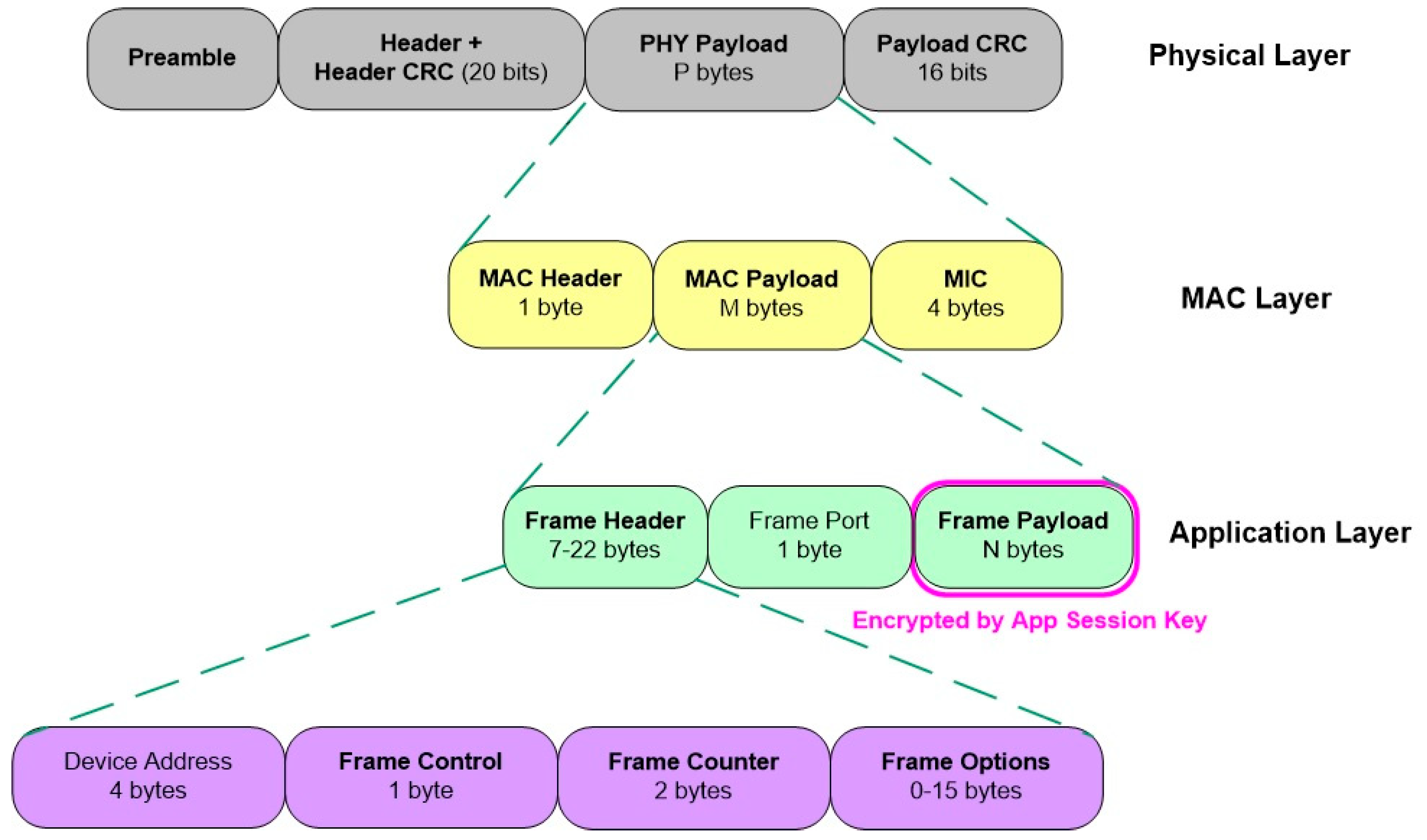
2.2.2. LoRa Network Architecture

Figure 3 [40] shows the network architecture of a LoRa. LoRaWAN allows the end nodes or LoRa devices to interact with gateways through LoRa. Gateways send raw LoRaWAN frames from devices to a network server using a higher throughput internet. Gateways are the only bidirectional units also called protocol converters, the network server is responsible for decoding the data packets sent by the LoRa devices and encoding the data into packets that should be sent back to the end nodes. Three classes of LoRa end-devices or nodes are defined based on downlink scheduling, namely class A, class B, and class C. Class A is best suited to battery-operated devices for efficient energy and achieves years of battery life, in LoRaWAN all of the devices support this class and downlink communication is available when the sensor nodes send some data. Class B end devices have timing-based receive slots, and receive a beacon from the gateway at synchronized times. Class C end devices can receive data continuously and stop receiving only when they are transmitting. All of the data sent by end nodes are processed and appropriate action is taken at the application server [41].
LoRa Frame Structure: The frame structure of the LoRa protocol for all of the layers is presented in Figure 4.
Physical Layer Frame: At the physical (PHY) layer, the preamble is the beginning of the LoRa frame, it is responsible for synchronization and defines the packet modulation technique, and the modulation is to be completed with the same spreading factor for the remaining packets. Ideally, the period of the preamble is 12.25 Ts. After the preamble, a 20-bit PHY Header with Header CRC is encoded using the highly reliable code rate, and the rest of the frame is encoded using the code rate mentioned in the PHY Header. The length of the payload and whether the 16-bit payload CRC is contained within the frame are also included in the PHY header. Payload CRC is present only in the uplink frames in a LoRa network. The MAC Frame is contained in the PHY payload.
MAC Layer Frame: A MAC header, a MAC payload, and a Message Integrity Code (MIC) make up the MAC layer packet. Its header specifies two things, the version of the protocol and the message kinds, it can also indicate the management frame or data frame, whether it is sent downlink or uplink, and whether an acknowledgment is required or not, it is also able to indicate that the message is manufacturer-specific. In a join procedure for end-node activation, the MAC Payload might be replaced by join accept or join request messages. The MIC value is computed using the whole MAC Header and MAC Payload portion when using a network session key (Nwk SKey). The MIC value helps to authenticate the end node and prevent message forgery.
Application Layer Packet: In an application layer the MAC payload consists of three things, a Frame Header, a Frame Port, and a Frame Payload. Based on the application type, the value of the Frame Port is defined. The application session key (App-SKey) is used to encrypt the Frame Payload value, AES 128 algorithm is used in the encryption.
The LoRa network performance analysis is discussed in this section. The analysis begins with the data rate, then the LoRa sensitivity is discussed, and finally the link budget analysis is presented.
(i) Spreading Factor (SF): The number of chips utilized to represent a symbol is found by the Spreading Factor (SF) value The greater the SF value, the more chips are used to represent a symbol, implying that the receiver will have more processing gain. As a result, the receiver will be able to accept data signals with a negative (Signal to Noise Ratio) SNR value. CSS uses spreading factors from 7 to 12;
(ii) Bandwidth (BW): The frequency range of the chirp signal which carries the baseband data is called the bandwidth;
(iii) Code Rate (CR): LoRa modulation provides a forward error correction to every data stream (FEC). Encoding 4-bit data along with redundancies into 5-bit, 6-bit, 7-bit, or even 8-bit does this. Usage of the redundancy helps the LoRa signal tolerate short interferences. The value of CR has to be modified based on the settings of the channel utilized for data transmission. If the channel has too many interferences in, then it is suggested to surge the CR value. However, by increasing the CR value, the transmission time will be increased;
(iv) Data Rate: The data rate, also called the bit rate, is used to represent the transmission speed. Usually, it is measured in bits per second and is known as the total number of bits that can be transferred from the transmitter to receiver during a transmission.
R b = SF [ 4 4 + CR ] 2 SF BW
where,
  • Rb = Data rate in bits per second
  • SF = Spreading factor (6,7,8,9,10,11,12)
  • BW = Bandwidth (10.4, 15.6 20.8, 31.25, 41.7, 62.5, 125, 250, 500)
  • CR = Code rate (1,2,3,4);
(v) Receiver Sensitivity: The least signal intensity that a receiver can sense is measured by the receiver sensitivity. It informs us of the weakest signal that a receiver can detect and analyze. The sensitivity of the receiver is measured in decibels (dBm). The typical range for the receiver sensitivity of LoRa is up to −130 dBm. The various parameters that affect the receiver sensitivity are the receiver noise figure (NF), BW, and signal to noise ratio (SNR). Usually, the noise figure is fixed based on the implemented hardware. SNR is required by the modulation scheme. SNR and BW are important variables to be considered while designing the LoRa. The formula for calculating the receiver sensitivity of LoRa is mentioned below.
S = 174 + 10 log 10 BW + NF + SNR  
(vi) Link Budget: The link budget is calculated using transmitted power and receiver sensitivity. It is also known as received power. The formula for the link budget of LoRa is mentioned below Equation (3).
  L i n k   B u d g e t ( d B m ) = ( T r a n s m i t t e d   P o w e r ( d B m ) + R e c e i v e r   S e n s i t i v i t y ( d B m ) )  

2.3. Literature Gap

In the previous studies, the researchers have implemented wireless technologies to enhance the safety of workers. Followed by wireless technologies, the different studies have utilized IoT-based systems to monitor workers in real-time on the construction site. The primary element that is vital during the implementation of IoT-based system on the construction site is the wireless communication protocol [27] because, on the construction site, an effective communication protocol empowers data transmission with reliability. Limited studies have utilized wireless communication protocols that consume low energy and offer long-range transmission, which is an important requirement for IoT implementation. Along with this, no study has implemented the IoT-based system with the integration of Zigbee and long-range (LoRa) for the construction site, and also no hardware customization is identified where the system monitors both the worker’s safety and the health of the construction site.

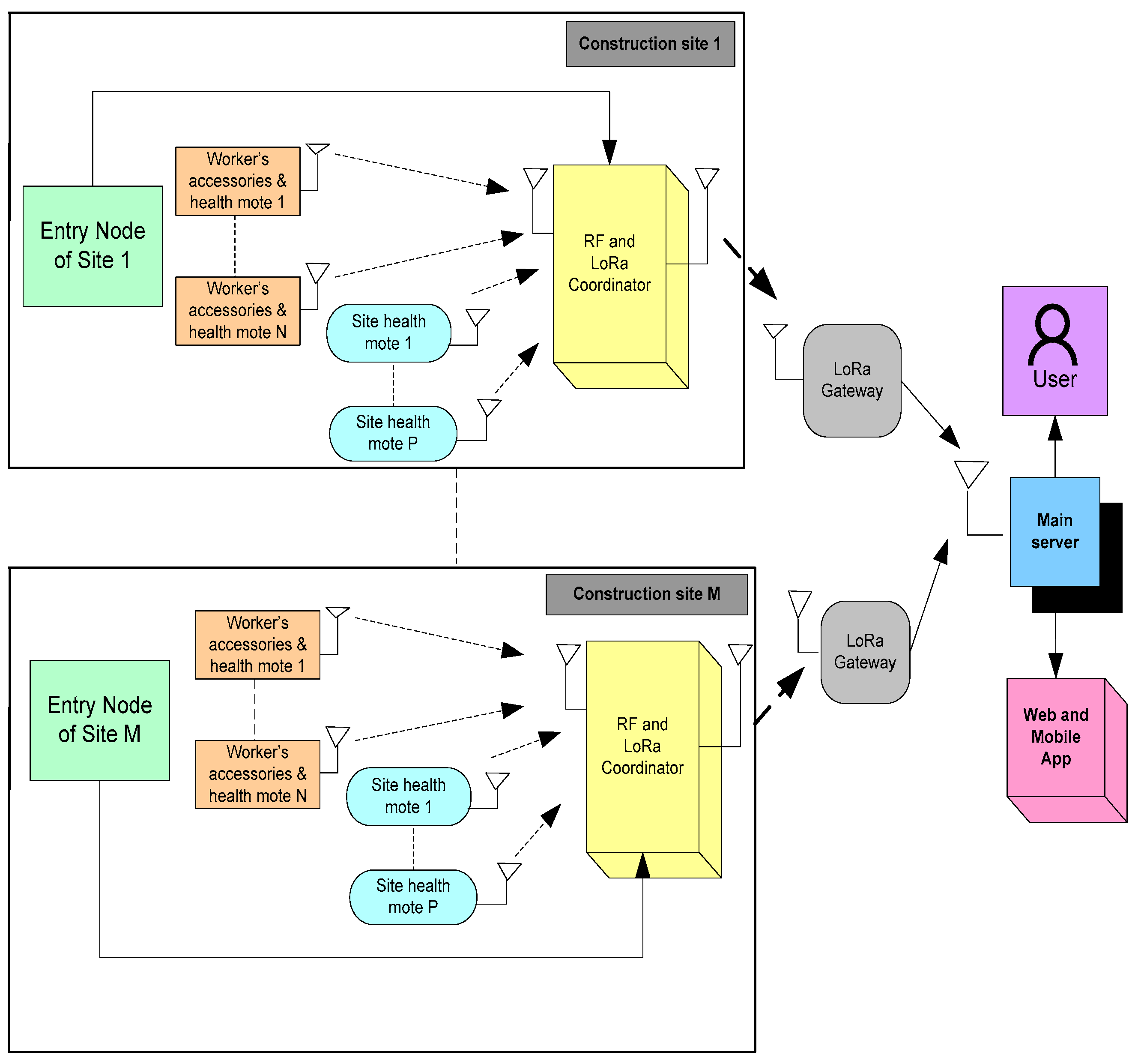
3. Proposed Architecture

The safety of construction employees on the job site is an important factor in maintaining their health. In this case, keeping track of each worker’s health and the environmental parameters of the construction site is crucial. As emergent technologies enable the establishment of a real-time monitoring systems through internet connectivity, the monitoring of workers’ health status and construction sites’ health status is attainable. However, real-time monitoring is only possible if the construction site is equipped with modern communication and sensor infrastructure. To implement this type of system, an architecture is specially presented to the construction site for worker safety, using advanced wireless communication and sensors.
Figure 5 shows the proposed architecture, in which the architecture is an integration of six components, such as entry node, accessories detection and health mote, site health mote, coordinator node, LoRa gateway, and main server. As previously stated, the integration of sensors and communication technology is essential in constructing a real-time monitoring system. The entry node is positioned at the entrance of the construction site to identify the worker’s entry, as well as whether the worker is wearing a helmet, or not using an RFID reader. The accessories’ detection and health mote component consist of several individual motes, namely goggles and helmet detection mote, worker health monitoring mote, shoe detection system, and gloves’ detection system. The site health detection mote consists of different sensors for monitoring temperature, humidity, fire, smoke, and vibrations in the site.
All of the accessories and health detection systems are arranged on the bodies of all of the workers for monitoring their safety status regularly. All of the environmental parameters of the construction site are monitored with the help of a health detection mote. These detection systems include particular sensors and Zigbee RF communication which allow the reading of the worker’s health parameters and sending the information to a local server placed in the premises of the construction area. Whenever the RF connectivity with LoRa gateway is disconnected or lost, then the recorded data is stored in the local memory. It helps to establish connectivity between the LoRa-based gateway and detection system with reliable connectivity and it is feasible to communicate with the LoRa gateway as it is integrated with multiple wireless communication protocols, namely Zigbee and LoRa. For low power communication, both LoRa and Zigbee communication are integrated in the architecture as it provides the open licensed spectrum. The local server transmits the status of each detection on a regular basis to the LoRa-based gateway.
The LoRa-based gateway is similarly compatible with a variety of communication protocols; however, in this case, the gateway is also equipped with a Wi-Fi modem, allowing sensor data from the detection system to be uploaded to the main server over the internet protocol (IP). Because the RF packets received from the detection system do not permit logging the data on the cloud server, the Wi-Fi modem was integrated. The data are available on the main server, where the authority may track the status of each individual worker at each construction site as well as the site’s environmental factors in real time. Authorities can use the online application and mobile app based on the primary server to obtain an individual’s status. This architecture allows the authorities to identify the status of the workers, in terms of the number of workers who entered the construction site, the number of unauthorized people who attempted to enter the premises, and the health of the construction site. Finally, the full architecture enables the building site to integrate wireless infrastructure and environment.

4. Hardware Customization

This section presents the necessity of hardware customization for the safety of construction workers. The customization helps the scholar to design and develop the hardware as per the requirements and applications. In general, to design any hardware mote, the important parameter to be considered is power consumption. Since the hardware is deployed in the outdoor environment and operates them using batteries, power consumption analysis is crucial. Every component which is used in the hardware mote has to utilize less power in both active and sleep states. The wireless communication protocol plays a significant role in the power consumption of the node, to minimize the power consumption, in this study we have chosen 2.4 GHz Zigbee and 433 MHz LoRa communication. Along with communication, the controller plays a major role in the hardware; the purpose of the controller is to read the data from input sensors and process it as per the application. Since all of the motes send low data, the ATmega328P low-power 8-bit microcontroller is chosen. The remaining components on the hardware motes operate with different voltages, based on their functionality, voltage converters are used to provide appropriate voltage to different components on the hardware mote. The details of the different modules involved in the proposed architecture are explained below.

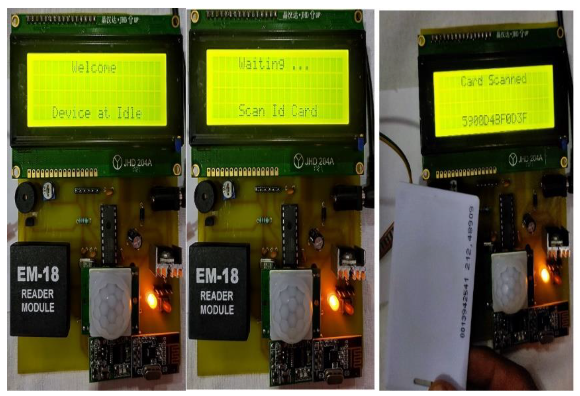
4.1. Accessories Detection and Health Mote

Different modules are integrated into the “accessories detection and health mote” for monitoring the multiple PPE equipment statuses and the health of the construction workers on the site, to ensure their safety. Helmet and Goggle Detection Mote, Worker Health Monitoring Mote, Gloves’ Detection System, and Shoe Detection System are the components that are part of the accessories’ detection and health mote. Along with these motes, an additional system is placed at the entrance of the site for identification to identify the worker using RFID technology, as shown in Figure 6. It helps to identify and restrict unauthorized persons entering the construction site.
The customized board for the workers’ identification detection system is shown in Figure 7.
It consists of a PIR Sensor, RFID Reader, Microcontroller, LCD, Power Supply Unit, Buzzer, and 2.4 GHz RF transceiver. This circuit is placed at the entrance of the construction site to monitor the entry of any person into the site. PIR is a passive infrared sensor, an input device used to monitor human movement and alerts the microcontroller whenever anyone enters the site, the microcontroller simultaneously reads the data from the RFID reader to check whether the person is a valid person or an unauthorized person.
The reader reads the RFID card data and compares it with the stored valid card number, if the number is found in the saved data then it means the person is wearing a helmet and is an authorized person, otherwise he/she is not wearing a helmet or an unauthorized person is trying to enter the site. A buzzer is an output device used to alert through sound, it is connected to the microcontroller. If a person without a helmet or unauthorized person enters the site, then the controller rings the buzzer and alerts the nearby people, simultaneously the same information is updated to the RF and LoRa coordinator through the RF transceiver. LCD is an output device and helps to display the status of all of the operations performed by the controller. Table 1 provides all of the technical specifications of all of the components used in the customized board of entry node.

4.1.1. Helmet and Goggles’ Detection Mote

Wearing a helmet on the construction site is highly important to save people from unexpected injuries. The purpose of the helmet and goggle detection mote is to check whether the worker is wearing a helmet or not, using an eye blink sensor. Workers might remove their helmets after they enter the site, monitoring it on a regular basis is very important to notify the worker and the management and to reduce the risk. Eye protection is also important for workers since a lot of dust particles are present on the construction site. The goggles and helmet are attached to each other to protect the eyes from dust and an eye blink sensor is placed on the goggles to monitor the eye blink continuously, if the eyeblink sensor detects the eye lid movement regularly then it means the worker has worn the helmet, otherwise the helmet was removed. Every helmet is embedded with a RFID card through which it can be detected who has removed their helmet, a buzzer placed on the helmet rinngs continuously to alert the worker when eye lid movement is not detected and the same information is updated to management in the local server using the RF Transceiver, as shown in the Figure 8a. The customized board for helmet detection is shown in Figure 8b, an eye blink sensor on the goggles is integrated in this mote, which helps to detect whether the worker is wearing the helmet or not.
Moreover, the RFID tag integrated with this helmet is for confirming the identity during entry into construction site. The IEEE 802.15.4-based Zigbee module works on 2.4 GHz frequency-based wireless communication and its use in detection mote allows the information to be sent to the local server with respect to the firmware instructions embedded in the controller. The technical specifications of the modules used in the helmet and goggle detection mote are listed in Table 2.

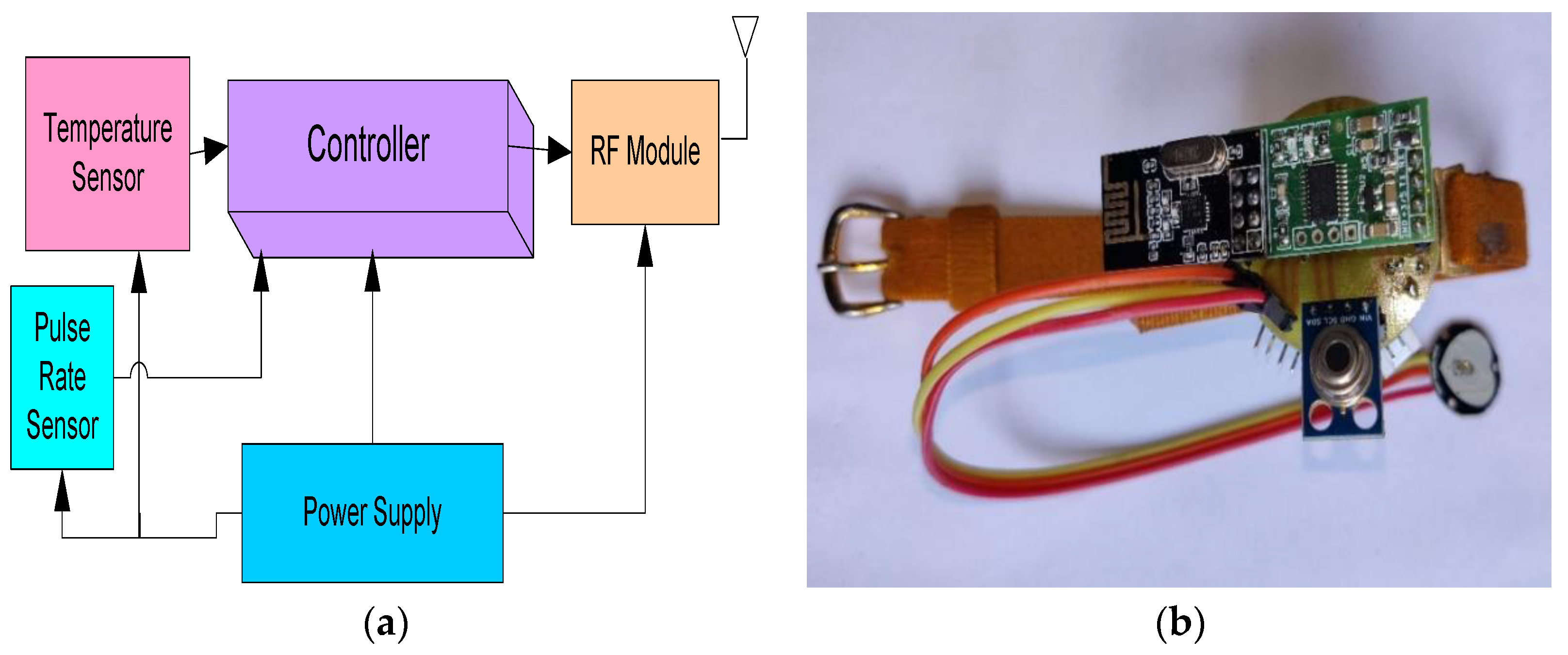
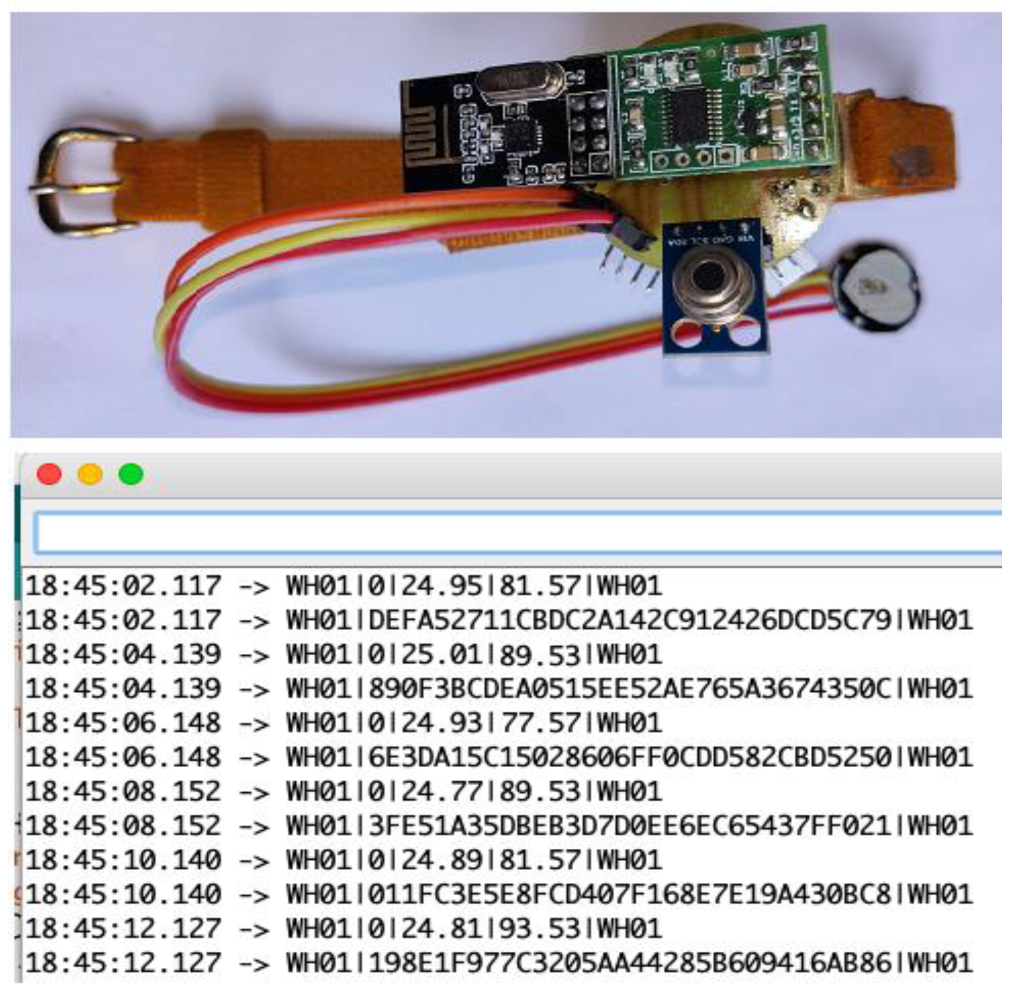
4.1.2. Worker Health Monitoring Mote

Adults and elders usually work in the construction field and they work very hard continuously throughout the day, so that monitoring their health parameters is very important in predicting any health issues in them. The health parameters of the worker, such as body temperature and pulse rate, are continuously measured using this mote and updates the same information through RF communication, as shown in Figure 9a.
The body temperature and pulse rate are basic health parameters that assist in finding any abnormal health condition of the workers. This mote alerts the main server to take necessary action immediately and provide assistance to the worker to save their health before it becomes a critical condition. This mote runs on battery power and moreover the components embedded in the mote are compatible with the battery power supply, as they are low power consuming components.
The customized hardware for the health detection of workers is shown in Figure 9b, an infrared-based non-contact temperature sensor MLX90614 is used to detect the temperature, it is capable of measuring the temperature in the range of −70 °C to 382 °C and communicates through a serial inter-integrated communication (I2C) protocol and a pulse sensor is used to monitor the heart rate. This mote is interconnected with the shoe detection system and gloves’ detection system through RF communication, technical specifications of each and every module used in worker health monitoring mote are listed in Table 3.

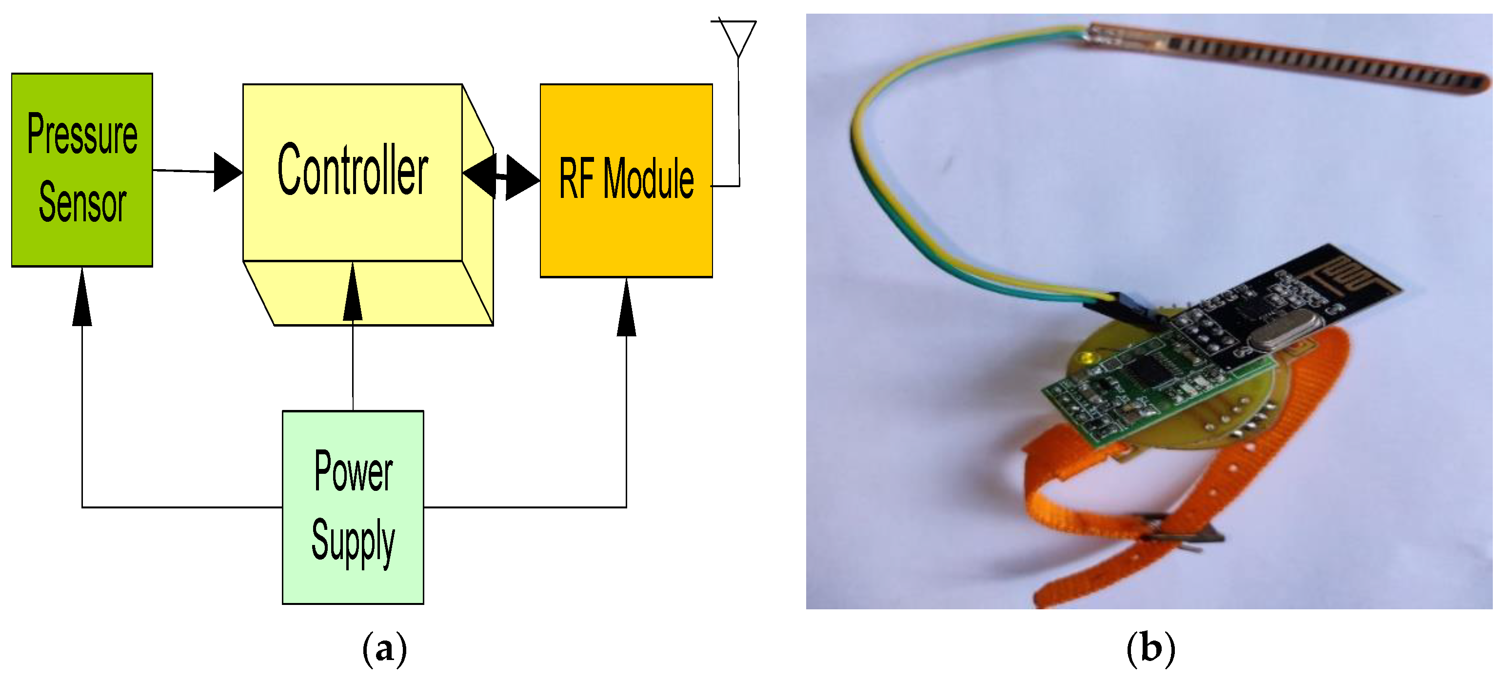
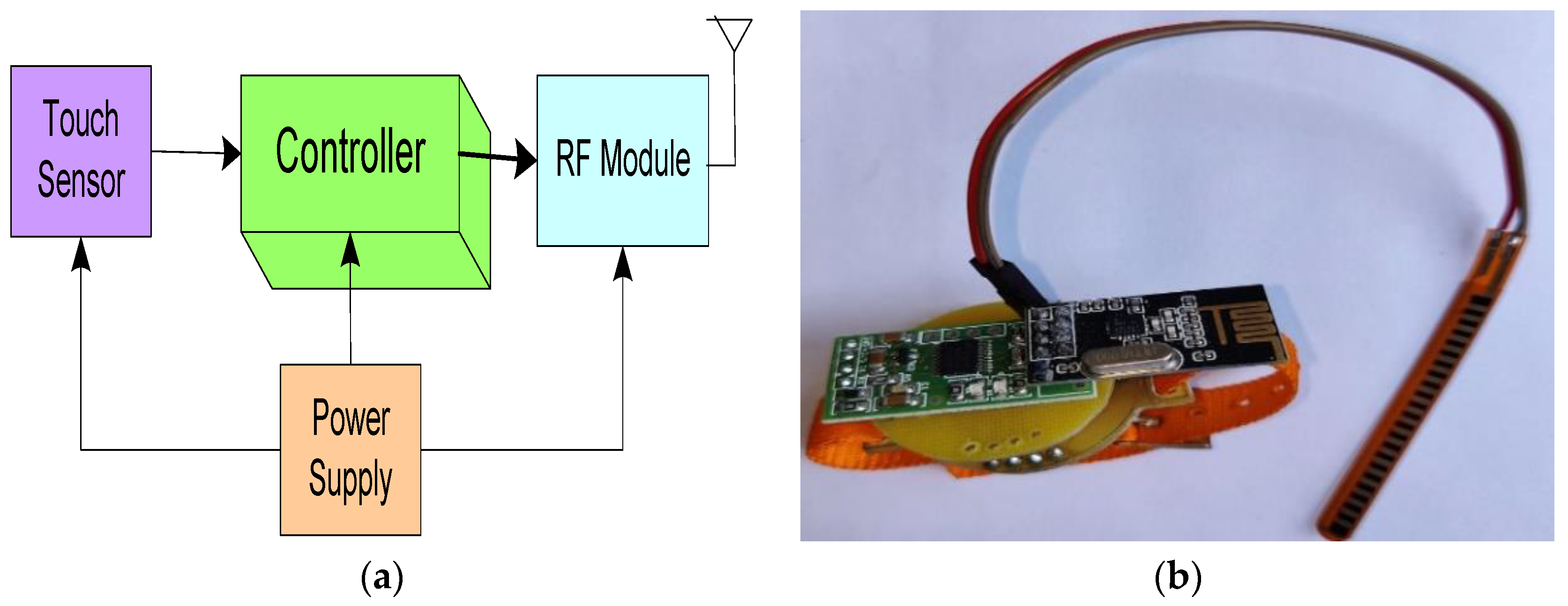
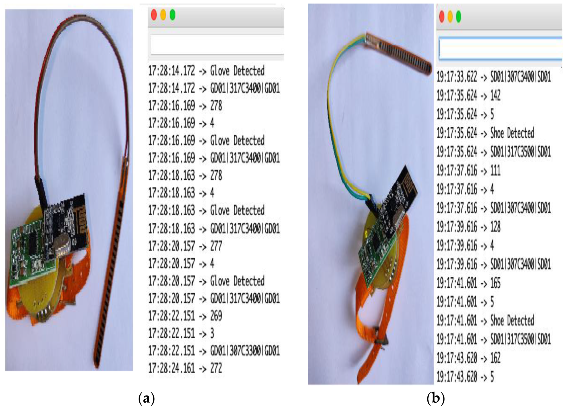
4.1.3. Shoe Detection System

Most of the workers work with and in cement and continuously exposing the legs to cement is not good for the feet. A pressure sensor-based shoe detection system is used to detect whether the worker has worn shoes or not, as shown in Figure 10a.
This interconnects with the health monitoring mote through an RF transmitter. The health monitoring mote will alert the person to wear shoes. The customized hardware of shoe detection is shown in Figure 10b. A Force Sensing Resistor (FSR) sensor is used to detect the pressure of the person with a buzzer to alert the worker and an RF module is used for wireless communication. Technical specifications of all of the modules used in the shoe detection mote are listed in Table 4.

4.1.4. Gloves Detection System

Gloves are used to protect the palms and hands of the workers. A touch sensor-based gloves’ detection system is used to check whether the worker is wearing gloves or not. The detection system is also interconnected with the worker’s health mote through the RF transmitter, as shown in the Figure 11a.
The touch sensor connected in the gloves’ detection system helps to check whether the person is wearing gloves or not. The touch sensor works as a digital sensor, can send only two logic states either 0 or 1: the wearing of gloves and not wearing of gloves, based on the logic sent by the touch sensor, the microcontroller will be taking an appropriate action, as shown in Figure 11b. Technical specifications of all of the modules used in the gloves’ detection mote are listed in Table 5.

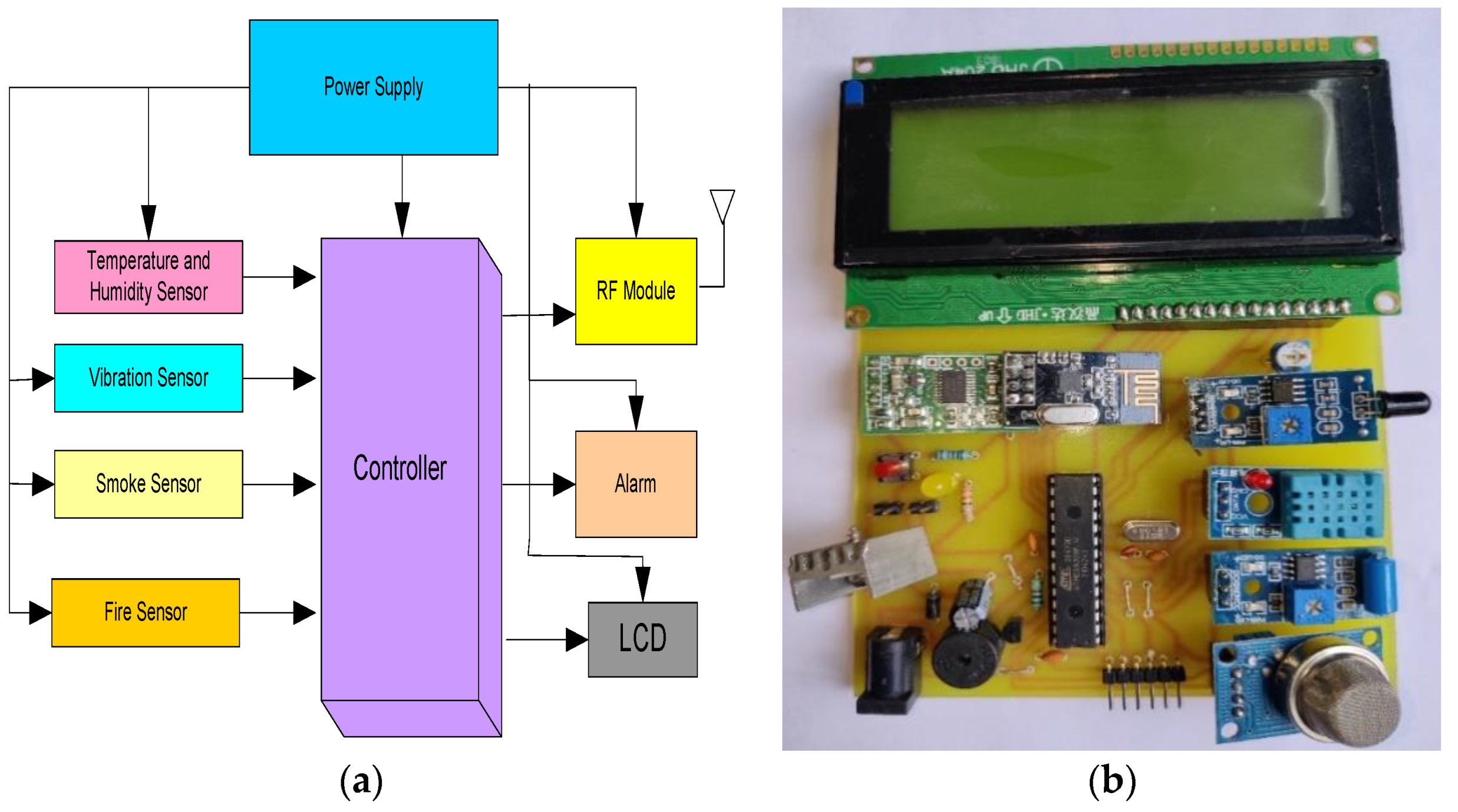
4.2. Site Health Monitoring Mote

The site health monitoring mote consists of various sensors to monitor the environmental parameters, such as temperature, humidity, fire and smoke, and vibrations in the site, as shown in Figure 12a.
Any disaster may occur in sites under construction, such as fire accident, collapsing of the building, gas leakage etc., which may lead to injuries to workers. A customized mote for detection of these important parameters, such as temperature, humidity, smoke/gas leakage, fire, and vibrations in the site is designed, as shown in Figure 12b. It consists of all of the sensors along with LCD to display the values and a rf module is also integrated to communicate wirelessly to the RF and LoRa coordinator. All of the technical specifications of each and every module used in the site health monitoring mote are listed in Table 6.

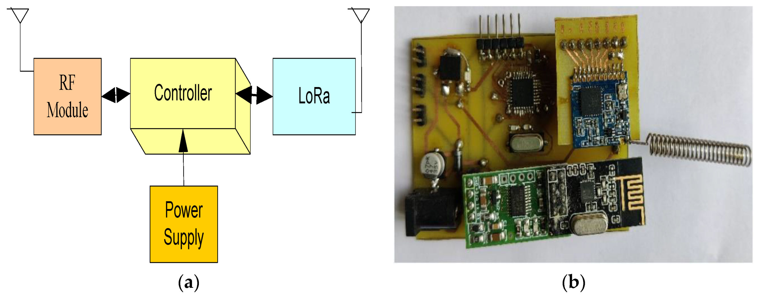
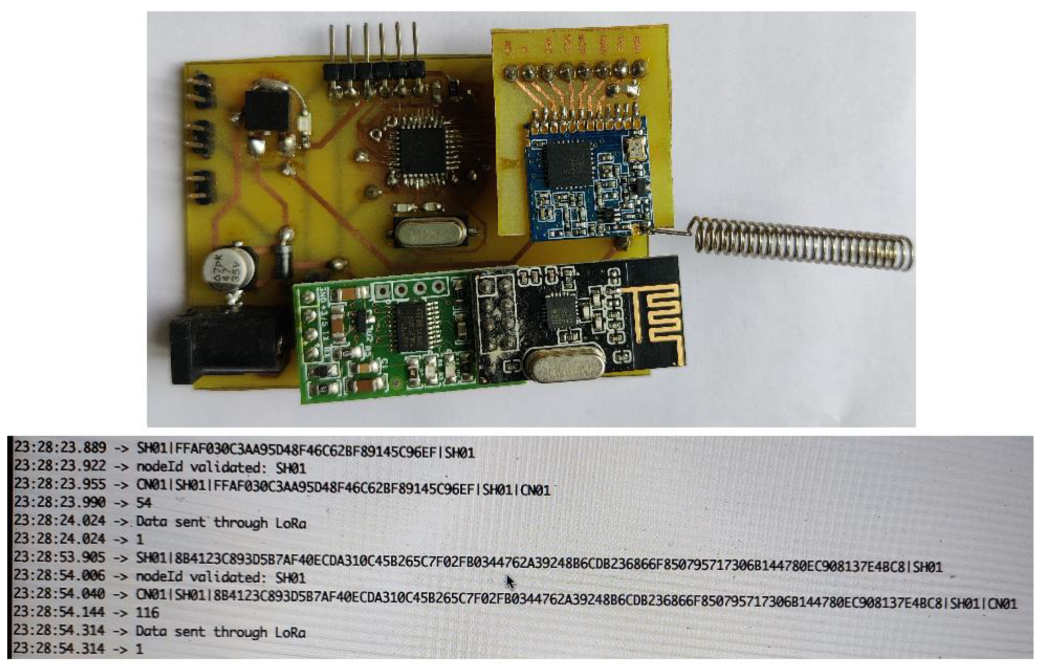
4.3. RF- and Lo-Ra-Based Coordinator Node

The RF and LoRa-based coordinator is designed and integrated into the architecture for improving the connectivity for maintaining stable communication between accessories detection, health mote, and gateway. It consists of two different wireless communication technologies i.e., 433 MHz-based long-range (LoRa) and IEEE 802.15.4-based Zigbee module, as shown in Figure 13a.
Moreover, it monitors and supervises all of the detection modules of the individuals and sends the sensor information to the gateway. The RF- and LoRa-based coordinator customized board is shown in Figure 13b, it consists of a RF transceiver, Microcontroller, LoRa Module, and power supply unit. Technical specifications of all of the modules used are listed in Table 7.

4.4. LoRa-Based Gateway

The purpose of the LoRa-based gateway is to receive LoRa-modulated RF messages from the RF and LoRa Coordinator and sends the same information to the main server using the Internet. The block diagram is shown in Figure 14a; it uses the ESP8266 Wi-Fi module and LCD.
The customized hardware of the LoRa gateway is shown in Figure 14b, the ESP8266 module helps to connect to the Internet through Wi-Fi. The technical specifications of all of the modules are listed in Table 8.

5. Performance Analysis

As discussed in Section 2.2, the performance analysis of the LoRa network is evaluated by configuring five transmission parameters, such as transmission power (PTr), carrier frequency (CF), bandwidth (BW), code rate (CR), and spreading factor (SF). The data rate, link budget, and receiver sensitivity are the evaluation metrics that are employed to analyze the performance of the LoRa network by configuring the above-mentioned five network parameters. The analysis is as follows:

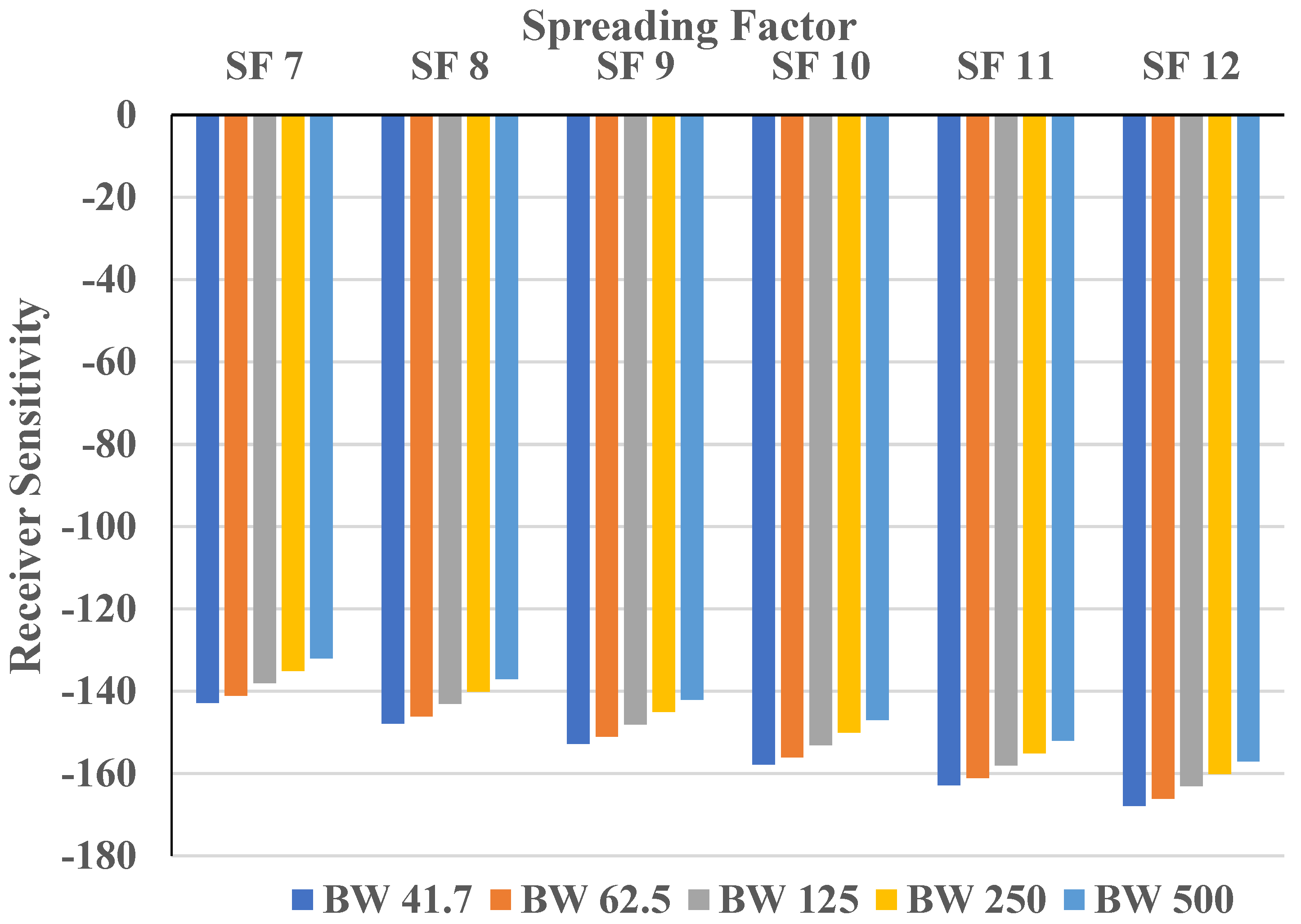
5.1. Receiver Sensitivity

As discussed earlier in Section 3, the LoRa sensitivity is based on the bandwidth, noise figures, and spreading factor parameters for its calculation. Equation (2) is utilized to calculate the receiver sensitivity. SNR is fixed for a particular spreading factor. The SNR value is −7.5 dB, −10 dB, −12.5 dB, −15 dB, −17 dB and −20 dB for SF 7, SF 8, SF 9, SF10, SF 11, and SF 12, respectively.
The above SNR value is chosen based on the SF for calculating receiver sensitivity. The bandwidth values considered here are 41.7 kHz, 62.5 kHz, 125 kHz, 250 kHz, and 500 kHz. In general, the receiver sensitivity is a negative value; for example, −132 dBm, if the value increases further then it means poor sensitivity. Figure 15 shows the receiver sensitivity for the spreading factors 7 to 12; the lowest sensitivity is observed for SF 12 at BW 41.7 kHz and the highest is observed for SF 7 at BW 500 kHz. LoRa sensitivity values are presented in Table 9.

5.2. Data Rate

The evaluation of the data rate is carried out with Equation (1). The input parameters of the data rate are BW, SF, and CR. Here we have evaluated the data rate of LoRa individually for SF 7 to SF 12 by varying BW from 41.7 kHz to 500 kHz and by CR from 1 to 4. As shown in Figure 16, for all of the spreading factors at a particular bandwidth, as CR increases the data rate decreases exponentially.
For example, for SF 7, the data rate calculated for BW 41.7 at CR 1 has a maximum of 1824 bps and when the CR value increases to 4, the data rate decreases to 1140 bps. In the overall calculations, the maximum value of the data rate, 21,875 bps, is observed at BW 500 at CR 1 for SF 7, and the minimum value of the data rate, 61 bps, is observed at BW 41.7 at CR 4 for SF 12. Table 10 represents the data rate at different spreading factors, and the plots are illustrated in Figure 16.

5.3. Link Budget

The link budget is evaluated with Equation (3), it is basically the sum of the transmitter power and receiver sensitivity. Five bandwidths 41.7 kHz, 62.5 kHz, 125 kHz, 250 kHz, and 500 kHz are considered for the SF 7–12 at different transmitting powers while calculating the link budget. The transmitting powers considered are 2 dB, 5 dB, 8 dB, 11 dB, and 14 dB. Table 11 represents the link budget for each transmitter and the plots are illustrated in Figure 17. At a particular transmission power, the link budget for any bandwidth decreases as the spreading factor increases. For a transmission power of 2 dB, BW 41.7 kHz the link budget is -140.79 dB at SF 7, the link budget decreases to −1145.79 dB as SF increases to 8, and at SF 12 the least link budget of −1165.79 bB is observed. If the BW is increased, then the link budget also increases, at 2 bB transmission power, SF 7 the link budget increases from −1140.79 dB to −1139.04 dB as the BW increases from 41.7 kHz to 62.5 kHz, and the overall highest link budget is observed at a transmission power of 14 dB for a SF 7 and BW 500.

6. Real-Time Implementation

This section covers the real-time deployment of the customized sensor boards, gateway, and the sensors’ data outputs are presented. The real-time implementation of the overall system is shown in Figure 18. The entry detection mote is placed at the entrance of the construction site to monitor the entrance of the workers with helmets using RFID. Wearable motes are developed to monitor the status of PPE equipment and the health monitoring of workers. A mote for monitoring the environmental parameters and the health conditions of the construction site is also deployed to sense the parameters, such as temperature, humidity, fire, smoke, gas, and vibrations on the site. To communicate the data from the site to a local server, a RF and LoRa coordinator is developed and to make all of the data available to the user and the management, a LoRa-based gateway is also developed and deployed on the construction site.
Entry node: The purpose of the entry node is to detect the movement of workers and check the availability of helmets at the entrance of the construction site. The PIR sensor senses movement at the entrance, if a valid RFID card is detected then an authenticated person with helmet is entering the site, otherwise an alarm will ring. LCD is arranged in this mote to observe the various states of this mote. Figure 19 illustrates the entry mote with different operations, such as idle mode, scanning mode, and validating the card.
Shoe and Gloves’ detection: Shoe and gloves’ detection motes are wearable motes, whenever they are worn, no alert will be sent, otherwise an alert information is sent to the health mote of the workers. A touch sensor is used in the gloves’ detection and a FSR sensor is used in shoe detection; every few minutes, these sensors’ status is checked by the microcontroller and if they are found to be removed, then an alert message is sent to the health mote of the same person using the 2.4 GHz RF transceiver. The real-time implementation of these two motes, along with the output in the serial monitor, is shown in Figure 20.
Workers’ health monitoring: Physiological parameters, such as temperature and heart rate of the worker, are monitored using this wearable mote. An IR-based temperature sensor MLX90614 is used to monitor the body temperature and a pulse rate sensor is used to monitor the heartrate of workers. These two data are continuously monitored by the microcontroller and these data, along with other motes relating to information about the worker, are sent to the RF coordinator using the RF transceiver. The real-time implementation of this mote and its output in the serial monitor is shown in Figure 21.
Site health monitoring: Environmental parameters’ monitoring is realized using this mote. Multiple sensors are interfaced in this mote to observe temperature, humidity, fire, smoke, gas, and vibrations in the site. DHT11 is used to monitor the temperature and humidity, a flame sensor is used to detect fire, a MQ-2 sensor is used to detect smoke and gas, and a vibration sensor is used to detect any vibrations on the construction site. All of these parameters are very important to monitor on the site to predict any risk on the site and to take necessary actions to prevent any further damage. All of these sensors’ information is collected by the microcontroller and the same is sent to the RF coordinator using the RF transceiver. LCD is interfaced to observe the values of all of the sensors and the real-time implementation of this mote, their output values in LCD and serial monitor output are shown in Figure 22.
RF and LoRa coordinator: Data sensed by various motes are communicated to the RF and LoRa coordinator using the RF; the overall data of each and every worker and construction health monitoring site are converted into LoRa convenient formats for further transmission to the LoRa gateway. The real-time implementation of this coordinator, along with its serial monitor output, is shown in Figure 23.
Gateway: The gateway consists of the LoRa and ESP8266 Wi-Fi module, it receives the data from the LoRa coordinator and uploads the same to the cloud, using the ESP8266 module. LCD is also interfaced to this module to check the communication status. Being able to monitor the status of all of the workers and the construction site from anywhere makes the job of supervisors and owners very easy. Real time implementation is shown in Figure 24.
The real-time setup of the complete proposed system is shown in Figure 25.

7. Conclusions

Real-time monitoring of workers’ health and the construction site plays a significant role in enhancing the infrastructure of the construction site. Furthermore, past research has shown that using digital technologies, such as the IoT in conjunction with wireless sensors, can improve building site safety. Inspired by these aspects, this study aims to integrate 433 MHz LoRa, 2.4 GHz Zigbee communication, and Wi-Fi for establishing an IoT-based system on the construction site for monitoring of the workers’ and the construction site’s health in real-time. As part of the system implementation in real-time, a hybrid architecture is proposed in this study and implemented multiple nodes with customized hardware are based on 2.4 GHz Zigbee, 433 MHz long-range (LoRa) and Wi-Fi. Furthermore, in the analysis of the evaluation metrics of LoRa, it is concluded that the lowest sensitivity is observed for SF 12 at BW 41.7 kHz and the highest is observed for SF 7 at BW 500 kHz; the maximum value data rate is observed at BW 500 KHz at CR 1 for SF 7, and the minimum data rate is observed at BW 41.7 at CR 4 for SF 12.

Author Contributions

Conceptualization, G.A.K.; methodology, A.R.; validation, S.V.A. and M.R.; formal analysis, A.G. and S.S.A.; writing—original draft preparation, G.A.K.; writing—review and editing, M.R.; A.A. and A.S.A.; supervision, R.S. and A.R.; funding acquisition, S.S.A. All authors have read and agreed to the published version of the manuscript.

Funding

This study was funded by the Deanship of Scientific Research, Taif University Researchers Supporting Project number (TURSP-2020/215), Taif University, Taif, Saudi Arabia.

Institutional Review Board Statement

Not applicable.

Informed Consent Statement

Not applicable.

Data Availability Statement

Data in this research paper will be shared on request to the corresponding author.

Conflicts of Interest

The authors declare no conflict of interest.

References

  1. Fei, W.; Opoku, A.; Agyekum, K.; Oppon, J.A.; Ahmed, V.; Chen, C.; Lok, K.L. The Critical Role of the Construction Industry in Achieving the Sustainable Development Goals (SDGs): Delivering Projects for the Common Good. Sustainability 2021, 13, 9112. [Google Scholar] [CrossRef]
  2. Singh, R.; Gehlot, A.; Akram, S.V.; Thakur, A.K.; Buddhi, D.; Das, P.K. Forest 4.0: Digitalization of forest using the Internet of Things (IoT). J. King Saud Univ.-Comput. Inf. Sci. 2021, 1–15. [Google Scholar] [CrossRef]
  3. Construction Industry|Global Construction Trends|Market Prospects. Available online: https://www.market-prospects.com/articles/global-construction-industry-trends#:~:text=The%20construction%20industry%20has%20more,of%20GDP%20in%20developing%20economies (accessed on 14 March 2022).
  4. Alli, B.O. Fundamental Principles of Occupational Health and Safety Second Edition. Geneva Int. Labour Organ. 2008, 15, 2008. [Google Scholar]
  5. Synergies between Security and Productivity—Wcms_110380. Available online: https://www.ilo.org/wcmsp5/groups/public/@ed_protect/@protrav/@safework/documents/meetingdocument/wcms_110380.pdf (accessed on 14 March 2022).
  6. LO, Safety and Health at Work: A Vision for Sustainable Prevention. In Report to XX World Congress on Safety and Health at Work; International Labor Organization: Frankfurt, Germany, 2014; Available online: https://www.google.com/search?channel=crow5&client=firefox-b-d&q=LO%2C+Safety+and+Health+at+Work%3A+A+Vision+for+Sustainable+prevention.+In%3A+Report+to+XX+World+Congress+on+Safety+and+Health+at+Work%2C+International+Labor+Organization%2C+Frankfurt%2C+Germany%2C+2014 (accessed on 14 March 2022).
  7. Ashuro, Z.; Zele, Y.T.; Kabthymer, R.H.; Diriba, K.; Tesfaw, A.; Alamneh, A.A. Prevalence of Work-Related Injury and Its Determinants among Construction Workers in Ethiopia: A Systematic Review and Meta-Analysis. J. Environ. Public Health 2021, 2021, 9954084. [Google Scholar] [CrossRef]
  8. Umeokafor, N.; Evaggelinos, K.; Lundy, S.; Isaac, D.; Allan, S.; Igwegbe, O.; Umeokafor, K.; Umeadi, B. The pattern of occupational accidents, injuries, accident causal factors and intervention in Nigerian factories. Dev. Ctry. Stud. 2014, 4, 119–127. [Google Scholar]
  9. Health and Safety Executive. Underlying Causes of Construction Fatal Accidents-Review and Sample Analysis of Recent Construction Fatal Accidents. 2009. Available online: https://www.hse.gov.uk/construction/resources/phase1.pdf (accessed on 1 April 2022).
  10. Agenda, I. Shaping the Future of Construction a Breakthrough in Mindset and Technology; WEF: Geneva, Switzerland, 2016. [Google Scholar]
  11. Oesterreich, T.D.; Teuteberg, F. Understanding the implications of digitisation and automation in the context of Industry 4.0: A triangulation approach and elements of a research agenda for the construction industry. Comput. Ind. 2016, 83, 121–139. [Google Scholar] [CrossRef]
  12. Svertoka, E.; Saafi, S.; Rusu-Casandra, A.; Burget, R.; Marghescu, I.; Hosek, J.; Ometov, A. Wearables for Industrial Work Safety: A Survey. Sensors 2021, 21, 3844. [Google Scholar] [CrossRef]
  13. Maskuriy, R.; Selamat, A.; Maresova, P.; Krejcar, O.; David, O.O. Industry 4.0 for the Construction Industry: Review of Management Perspective. Economies 2019, 7, 68. [Google Scholar] [CrossRef] [Green Version]
  14. Häikiö, J.; Kallio, J.; Mäkelä, S.-M.; Keränen, J. IoT-based safety monitoring from the perspective of construction site workers. Int. J. Occup. Environ. Saf. 2020, 4, 1–14. [Google Scholar] [CrossRef] [Green Version]
  15. Awolusi, I.; Nnaji, C.; Marks, E.; Hallowell, M. Enhancing Construction Safety Monitoring through the Application of Internet of Things and Wearable Sensing Devices: A Review. In Proceedings of the ASCE International Conference on Computing in Civil Engineering 2019, Atlanta, GA, USA, 17–19 June 2019; pp. 530–538. [Google Scholar] [CrossRef]
  16. Jayanthi, N.; Thirumalai Raja, K.; Wadhwa, G.; Shneka, K.; Swathi, R. IoT Based-Civil Labour Safety Monitoring System in Construction Site. Turk. J. Comput. Math. Educ. TURCOMAT 2021, 12, 1723–1728. [Google Scholar]
  17. Almuhaya, M.A.M.; Jabbar, W.A.; Sulaiman, N.; Abdulmalek, S. A Survey on LoRaWAN Technology: Recent Trends, Opportunities, Simulation Tools and Future Directions. Electronics 2022, 11, 164. [Google Scholar] [CrossRef]
  18. Wu, F.; Wu, T.; Yuce, M.R. An Internet-of-Things (IoT) Network System for Connected Safety and Health Monitoring Applications. Sensors 2019, 19, 21. [Google Scholar] [CrossRef] [PubMed] [Green Version]
  19. Wu, T.; Wu, F.; Redoute, J.-M.; Yuce, M.R. An Autonomous Wireless Body Area Network Implementation towards IoT Connected Healthcare Applications. IEEE Access 2017, 5, 11413–11422. [Google Scholar] [CrossRef]
  20. Mahmud, M.S.; Wang, H.; Esfar-E-Alam, A.M.; Fang, H. A Wireless Health Monitoring System Using Mobile Phone Accessories. IEEE Internet Things J. 2017, 4, 2009–2018. [Google Scholar] [CrossRef]
  21. Wu, F.; Redoute, J.-M.; Yuce, M.R. A Self-Powered Wearable Body Sensor Network System for Safety Applications. In Proceedings of the 2018 IEEE Sensors, New Delhi, India, 28–31 October 2018; pp. 1–4. [Google Scholar] [CrossRef]
  22. Antolín, D.; Medrano, N.; Calvo, B.; Pérez, F. A Wearable Wireless Sensor Network for Indoor Smart Environment Monitoring in Safety Applications. Sensors 2017, 17, 365. [Google Scholar] [CrossRef]
  23. Awolusi, I.; Marks, E.; Hallowell, M. Wearable technology for personalized construction safety monitoring and trending: Review of applicable devices. Autom. Constr. 2018, 85, 96–106. [Google Scholar] [CrossRef]
  24. Park, J.; Marks, E.; Cho, Y.K.; Suryanto, W. Performance Test of Wireless Technologies for Personnel and Equipment Proximity Sensing in Work Zones. J. Constr. Eng. Manag. 2016, 142, 04015049. [Google Scholar] [CrossRef]
  25. Marks, E.; Teizer, J. Proximity Sensing and Warning Technology for Heavy Construction Equipment Operation. In Proceedings of the Construction research congress 2012: Construction challenges in a flat world, West Lafayette, IN, USA, 21–23 May 2012; pp. 981–990. [Google Scholar]
  26. Jin, R.; Zhang, H.; Liu, D.; Yan, X. IoT-based detecting, locating and alarming of unauthorized intrusion on construction sites. Autom. Constr. 2020, 118, 103278. [Google Scholar] [CrossRef]
  27. Chung, W.W.S.; Tariq, S.; Mohandes, S.R.; Zayed, T. IoT-based application for construction site safety monitoring. Int. J. Constr. Manag. 2020, 1–17. [Google Scholar] [CrossRef]
  28. Nguyen, H.A.D.; Nguyen, L.V.; Ha, Q.P. IoT-enabled Dependable Co-located Low-cost Sensing for Construction Site Monitoring. In Proceedings of the 37th International Symposium on Automation and Robotics in Construction, Kitakyushu, Japan, 27–28 October 2020; International Association for Automation and Robotics in Construction (IAARC): Kitakyushu, Japan, 2020; pp. 616–624. [Google Scholar] [CrossRef]
  29. Kanan, R.; Elhassan, O.; Bensalem, R. An IoT-based autonomous system for workers’ safety in construction sites with real-time alarming, monitoring, and positioning strategies. Autom. Constr. 2018, 88, 73–86. [Google Scholar] [CrossRef]
  30. Akram, S.V.; Singh, R.; AlZain, M.A.; Gehlot, A.; Rashid, M.; Faragallah, O.S.; El-Shafai, W.; Prashar, D. Performance Analysis of IoT and Long-Range Radio-Based Sensor Node and Gateway Architecture for Solid Waste Management. Sensors 2021, 21, 2774. [Google Scholar] [CrossRef] [PubMed]
  31. What Is Zigbee?—Definition from whatis.com. Available online: https://internetofthingsagenda.techtarget.com/definition/ZigBee (accessed on 16 March 2022).
  32. Tovar, E. IEEE 802.15.4: A Federating Communication Protocol for Time-Sensitive Wireless Sensor Networks. Chapter in book Sensor Networks and Configurations: Fundamentals, Techniques, Platforms, and Experiments; Springer: Berlin/Heidelberg, Germany, 2006; pp. 19–49. Available online: http://www.cister.isep.ipp.pt/docs/ieee_802_15_4__a_federating_communication_protocol_for_time_sensitive_wireless_sensor_networks/802/ (accessed on 16 March 2022).
  33. ZIGBEE Architecture (ZIGBEE Stack)—All Layers and Its Functions. Available online: https://electricalfundablog.com/zigbee-architecture-zigbee-stack-layers/ (accessed on 16 March 2022).
  34. Amin, I.; Saeed, A. Wireless Technologies in Energy Management. In Comprehensive Energy Systems; Elsevier Inc.: Amsterdam, The Netherlands, 2018; Volume 5, pp. 389–422. ISBN 9780128095973. [Google Scholar]
  35. Introduction to LoRa Technology. Available online: https://www.digikey.in/en/maker/blogs/introduction-to-lora-technology (accessed on 17 March 2022).
  36. White Paper|LoRaWAN and Multi-RAN Architecture. Available online: https://info.semtech.com/abi-research-white-paper?utm_campaign=ABI+Research+Whitepaper&utm_source=adwords&utm_medium=ppc&utm_term=what%20is%20lorawan&hsa_kw=what%20is%20lorawan&hsa_net=adwords&hsa_grp=121822778049&hsa_cam=12511627439&hsa_acc=8837864389&hsa_tgt=kwd-366235034612&hsa_ver=3&hsa_ad=538583136629&hsa_mt=b&hsa_src=g&gclid=Cj0KCQjwuMuRBhCJARIsAHXdnqNVaoRtm2ze3L8kYp2MZwLLj85CGz0CdnnFFeUtcc66H9GAkN08S1kaAh0SEALw_wcB (accessed on 17 March 2022).
  37. LoRa and LoRaWAN: A Technical Overview LoRa® and LoRaWAN®: A Technical Overview. 2020. Available online: https://lora-developers.semtech.com/uploads/documents/files/LoRa_and_LoRaWAN-A_Tech_Overview-Downloadable.pdf (accessed on 17 March 2022).
  38. Augustin, A.; Yi, J.; Clausen, T.; Townsley, W.M. A Study of LoRa: Long Range & Low Power Networks for the Internet of Things. Sensors 2016, 16, 1466. [Google Scholar] [CrossRef]
  39. Introduction to LoRa and LoRaWAN: What Is LoRa and How Does It Work? Available online: https://circuitdigest.com/article/introduction-to-lora-and-lorawan-what-is-lora-and-how-does-it-work (accessed on 17 March 2022).
  40. LoRa Architecture—LoRaWAN Tutorial. Available online: https://www.3glteinfo.com/lora/lora-architecture/ (accessed on 17 March 2022).
  41. LoRa-(Long Range) Network and Protocol Architecture & Frame Structure. Available online: https://www.techplayon.com/lora-long-range-network-architecture-protocol-architecture-and-frame-formats/ (accessed on 19 March 2022).
Figure 1. Zigbee Architecture (Zigbee Stack) Functions [31].
Sustainability 14 06280 g001
Figure 2. Different applications of Zigbee Communication Technology.
Sustainability 14 06280 g002
Figure 3. Network Architecture of a LoRa.
Sustainability 14 06280 g003
Figure 4. LoRa Frame Format.
Sustainability 14 06280 g004
Figure 5. Proposed System Architecture.
Sustainability 14 06280 g005
Figure 6. System at the entry point of construction site.
Sustainability 14 06280 g006
Figure 7. Customized Board of Entry Node.
Sustainability 14 06280 g007
Figure 8. (a) Helmet and Goggles’ Detection Mote; (b) Customized Hardware of Helmet and Goggles’ Detection Mote.
Sustainability 14 06280 g008
Figure 9. (a) Worker Health Monitoring Mote; (b) Customized Hardware of Worker Health Monitoring Mote.
Sustainability 14 06280 g009
Figure 10. (a) Shoe Detection System; (b) Customized Hardware of Shoe Detection System.
Sustainability 14 06280 g010
Figure 11. (a) Gloves’ Detection System; (b) Customized Hardware of Gloves’ Detection System.
Sustainability 14 06280 g011
Figure 12. (a) Site Health Monitoring Mote; (b) Customized Hardware of Site Health Monitoring Mote.
Sustainability 14 06280 g012
Figure 13. (a) RF and LoRa Coordinator (b) Customized Hardware of RF and LoRa coordinator.
Sustainability 14 06280 g013
Figure 14. (a) LoRa Gateway; (b) Customized Hardware of LoRa Gateway.
Sustainability 14 06280 g014
Figure 15. Receiver sensitivity of LoRa.
Sustainability 14 06280 g015
Figure 16. Data rate.
Sustainability 14 06280 g016
Figure 17. Link Budget.
Sustainability 14 06280 g017
Figure 18. Real time implementation of proposed system.
Sustainability 14 06280 g018
Figure 19. Entry Node operations in idle mode, scanning, and verifying state.
Sustainability 14 06280 g019
Figure 20. Gloves’ and Shoe detection motes along with serial monitor outputs. (a) shows the customized hardware for gloves detection and its corresponding output whether the gloves are detected or not in the serial monitor. Similarly (b) shows the customized hardware for shoes detection and its corresponding output whether the shoes are worn or not in the serial monitor.
Sustainability 14 06280 g020
Figure 21. Workers’ health motes along with serial monitor output.
Sustainability 14 06280 g021
Figure 22. Site health monitoring motes along with serial monitor outputs.
Sustainability 14 06280 g022
Figure 23. RF and LoRa Coordinator along with serial monitor output.
Sustainability 14 06280 g023
Figure 24. LoRa and Wi-Fi Gateway Module.
Sustainability 14 06280 g024
Figure 25. Overall System Setup.
Sustainability 14 06280 g025
Table 1. Technical Specifications of Entry Node.
ParameterSpecifications
Microcontroller:ATMega328P
Communication module:nRF24L01+ Wireless module (2.4 GHz)
Voltage converter:+5 V
PIR Sensor:HC-SR501
RFID Reader:EM 18 (125 KHz)
LCD:20 × 4 Alphanumeric Display
Buzzer:Piezo Passive Buzzer
Power trails:+5 V
Power jack:+12 V External power supply
Programming pins:FTDI and ICSP
Table 2. Technical Specifications of Helmet Detection Mote.
ParameterSpecifications
Microcontroller:ATMega328P
Communication module:nRF24L01+ Wireless module (2.4 GHz)
Voltage converter:+5 V
Eye Blink Sensor:Infrared-based sensor
RFID Tag:125 KHZ RFID Tag
Power trails:+5 V
Power jack:+5 V External power supply
Programming pins:FTDI and ICSP
Table 3. Technical Specifications of Worker Health Monitoring Mote.
ParameterSpecifications
Microcontroller:ATMega328P
Communication module:nRF24L01+ Wireless module (2.4 GHz)
Voltage converter:+5 V
Temperature Sensor:Infrared-based MLX90614
Pulse Rate Sensor:Heart rate sensor
Power trails:+5 V
Power jack:+5 V External power supply
Programming pins:FTDI and ICSP
Table 4. Technical Specifications of Shoe Detection Mote.
ParameterSpecifications
Microcontroller:ATMega328P
Communication module:nRF24L01+ Wireless module (2.4 GHz)
Voltage converter:+5 V
Pressure Sensor:Force Sensor
Power jack:+5 V External power supply
Programming pins:FTDI and ICSP
Table 5. Technical Specifications of Gloves’ Detection Mote.
ParameterSpecifications
Microcontroller:ATMega328P
Communication module:nRF24L01+ Wireless module (2.4 GHz)
Voltage converter:+5 V
Touch Sensor:Force Sensor
Power jack:+5 V External power supply
Programming pins:FTDI and ICSP
Table 6. Technical Specifications of Site Health Monitoring Mote.
ParameterSpecifications
Microcontroller:ATMega328P
Communication module:nRF24L01+ Wireless module (2.4 GHz)
Voltage converter:+5 V
Temperature and Humidity Sensor:DHT11
Smoke Sensor:MQ-2
Fire Sensor:Fire Flame Sensor
Vibration Sensor:Vibration detection module
Display:20 × 4 Alphanumeric LCD
Power trails:+5 V
Power jack:+12 V External power supply
Programming pins:FTDI and ICSP
Table 7. Technical Specifications of RF and LoRa Coordinator.
ParameterSpecifications
Microcontroller:ATMega328P
Communication module:nRF24L01+ Wireless module (2.4 GHz)
Voltage converter:+5 V
LoRa Module:SX1278 (433 MHz)
Table 8. Technical Specifications of LoRa Gateway.
ParameterSpecifications
Microcontroller:ATMega328P
LoRa Module:SX1278 (433 MHz)
Wi-Fi Module:ESP8266
Voltage converter:+5 V
Display:20 × 4 Alphanumeric LCD
Power jack:+12 V External power supply
Programming pins:FTDI and ICSP
Table 9. Receiver sensitivity of LoRa.
BW 41.7BW 62.5BW 125BW 250BW 500
SF 7−142.79−141.04−138.03−135.02−132.01
SF 8−147.79−146.04−143.03−140.02−137.01
SF 9−152.79−151.04−148.03−145.02−142.01
SF 10−157.79−156.04−153.03−150.02−147.01
SF 11−162.79−161.04−158.03−155.02−152.01
SF 12−167.79−166.04−163.03−160.02−157.01
Table 10. Data rate.
SF 7 SF 8
BW41.7BW62.5BW125BW250BW500 BW41.7BW62.5BW125BW250BW500
CR 11824273454691093821875CR 1104315633125625012500
CR 2152022794557911518229CR 286913022604520810417
CR 3130319533906781315625CR 37451116223244648929
CR 4114017093418683613672CR 4652977195339067813
SF 9 SF 10
BW41.7BW62.5BW125BW250BW500 BW41.7BW62.5BW125BW250BW500
CR 1586879175835167031CR 132648897719533906
CR 2489732146529305859CR 227140781416283255
CR 3419628125625115022CR 323334969813952790
CR 4367549109921974395CR 420430561012212441
SF 11 SF 12
BW41.7BW62.5BW125BW250BW500 BW41.7BW62.5BW125BW250BW500
CR 117926953710742148CR 1981462935861172
CR 21492244488951790CR 281122244488977
CR 31281923847671535CR 370105209419837
CR 41121683366711343CR 49892183366732
Table 11. Link Budget.
2 dB 5 dB
BW41.7BW62.5BW125BW250BW500 BW41.7BW62.5BW125BW250BW500
SF 7−1140.79−1139.04−1136.03−1133.02−1130.01SF 7−1137.79−1136.04−1133.03−1130.02−1127.01
SF 8−1145.79−1144.04−1141.03−1138.02−1135.01SF 8−1142.79−1141.04−1138.03−1135.02−1132.01
SF 9−1150.79−1149.04−1146.03−1143.02−1140.01SF 9−1147.79−1146.04−1143.03−1140.02−1137.01
SF 10−1155.79−1154.04−1151.03−1148.02−1145.01SF 10−1152.79−1151.04−1148.03−1145.02−1142.01
SF 11−1160.79−1159.04−1156.03−1153.02−1150.01SF 11−1157.79−1156.04−1153.03−1150.02−1147.01
SF 12−1165.79−1164.04−1161.03−1158.02−1155.01SF 12−1162.79−1161.04−1158.03−1155.02−1152.01
8 dB 11 dB
BW41.7BW62.5BW125BW250BW500 BW41.7BW62.5BW125BW250BW500
SF 7−1134.79−1133.04−1130.03−1127.02−1124.01SF 7−1131.79−1130.04−1127.03−1124.02−1121.01
SF 8−1139.79−1138.04−1135.03−1132.02−1129.01SF 8−1136.79−1135.04−1132.03−1129.02−1126.01
SF 9−1144.79−1143.04−1140.03−1137.02−1134.01SF 9−1141.79−1140.04−1137.03−1134.02−1131.01
SF 10−1149.79−1148.04−1145.03−1142.02−1139.01SF 10−1146.79−1145.04−1142.03−1139.02−1136.01
SF 11−1154.79−1153.04−1150.03−1147.02−1144.01SF 11−1151.79−1150.04−1147.03−1144.02−1141.01
SF 12−1159.79−1158.04−1155.03−1152.02−1149.01SF 12−1156.79−1155.04−1152.03−1149.02−1146.01
14 dB
BW41.7BW62.5BW125BW250BW500
SF 7−1128.79−1127.04−1124.03−1121.02−1118.01
SF 8−1133.79−1132.04−1129.03−1126.02−1123.01
SF 9−1138.79−1137.04−1134.03−1131.02−1128.01
SF 10−1143.79−1142.04−1139.03−1136.02−1133.01
SF 11−1148.79−1147.04−1144.03−1141.02−1138.01
SF 12−1153.79−1152.04−1149.03−1146.02−1143.01
Publisher’s Note: MDPI stays neutral with regard to jurisdictional claims in published maps and institutional affiliations.

