
Durable Icephobic Slippery Liquid-Infused Porous Surfaces (SLIPS) Using Flame- and Cold-Spraying


Materials Science and Environmental Engineering, Faculty of Engineering and Natural Sciences, Tampere University, Korkeakoulunkatu 6, 33720 Tampere, Finland
*
Author to whom correspondence should be addressed.
Sustainability 2022, 14(14), 8422; https://doi.org/10.3390/su14148422
Submission received: 10 May 2022
/
Revised: 29 June 2022
/
Accepted: 1 July 2022
/
Published: 9 July 2022
(This article belongs to the Special Issue Toward Sustainable Multifunctional Coatings)
Abstract
:Icing and ice accretion cause severe problems in different industrial sectors, e.g., in aircrafts, aviation traffic, ships, solar panels, and wind turbines. This can lead to enormous economic losses and serious safety issues. Surface engineering can tackle these problems by designing surface structures to work as icephobic coatings and, this way, act as passive anti-icing solutions. In this research, slippery liquid-infused porous structures were fabricated using flame- and cold-spraying to produce polymer (LDPE and PEEK) coatings, and impregnated with a silicone lubricant. Microstructural details, surface properties, wetting behavior, and cyclic icing–deicing behavior were evaluated via ice adhesion measurements, which show the potential performance of SLIPS designs. All these SLIPS showed low or medium-low ice adhesion after the first icing-deicing cycle and the best candidate showed stable performance even after several icing-deicing cycles.
Keywords:
anti-icing; SLIPS; polymers; cold spray; flame spray; icephobic; coating; icing wind tunnel; ice adhesion1. Introduction
Ice formation and accretion are natural phenomena that particularly take place in cold-climate countries and in both hemispheres [1]. Icing and ice accretion can cause serious safety and economic challenges that affect almost all life sectors such as infrastructure [2]; transportation and cargo [3]; power production, power lines and communication; wind turbines [4]; ships and marine vessels [5]; aircraft [6]; and many freezers and commercial and residential refrigerators [7]. Sustainable solutions are needed to tackle these challenges. Over the last decades, scientists and engineers have put great effort into studying the physicochemical mechanisms of freezing and developed anti-/deicing strategies to suppress ice build-up [8]. Deicing is associated with the removal of ice from surfaces, whilst anti-icing means the avoidance or delay of ice accretion on surfaces [9]. Icephobicity, in turn, is a surface property that can minimize ice adhesion on a solid surface [10], while icephobic surfaces that prohibit ice formation or snow are crucial for the reliable operation of equipment in extremely cold environments [11].
Several studies have been conducted to solve icing problems. In general, strategies for anti-/deicing can be classified into active and passive approaches. Active methods involve ice removal with external energy [12] and they use, e.g., electric heating [12,13,14], ultrasonic deicing systems [15,16,17], dynamic resonance systems and mechanical vibration [18], and deicing chemicals [19,20]. Nevertheless, these active deicing approaches usually depend on continuous heating or periodic vibration of the frozen locations with high energy, consuming and using chemicals and salts. Therefore, alternative methods which are more environmentally friendly and have less energy consumption are needed [8]. Surface engineering solutions can offer these passive and more sustainable approaches [21].
Superhydrophobic surfaces (SHSs) have been considered good candidates to serve as icephobic surfaces [22,23,24,25]. SHSs have been inspired by the lotus leaf, which repels water naturally due to the micro–nano hierarchical surface structure; it has a thin layer of nano-wax crystals that cover micro-sized papillae, reducing the water droplet contact area [26,27]. Synthetic SHSs have been distinguished by water repellency [28], self-cleaning [29], anti-corrosion [30] and anti-icing [22] abilities. However, SHSs have faced problems with their durability and long-standing behavior in different operating conditions that can limit their use. In general, the micro–nano-structures of SHS can be mechanically weak and tend to damage under physical stress [31] additionally, liquids with low surface tension such as organics can easily infiltrate the surface structure and eliminate the SHS’s water repellency. The trapped air cannot withstand external continuous pressure or dynamic conditions; additionally, the SHS can easily attract dust, contaminants, and organic pollutants to the surface and inside of the structure, and they are difficult to remove [32]. Moreover, research has shown that the icephobic behavior of SHSs can be easily corrupted because water has condensed inside the micro–nano-structure in sub-zero and high humidity weather [33].
Different surface engineering solutions are required to serve as anti-icing surfaces. Researchers have investigated slippery liquid-infused porous surfaces (SLIPS) as an alternative surface design to SHSs for anti-icing applications [34,35,36,37]. SLIPS have mimicked the Nepenthes pitcher plant, which reserves a thin water film inside micro-roughness surface structure and makes the pitcher slippery to insects [36]. SLIPS have been shown to acquire anti-icing, self-cleaning, anti-corrosion anti-adhesive, anti-fouling, and potential drag-reducing properties [38,39,40]. SLIPS can be synthesized by infusing lubricant (viscous oils) into porous or rough surfaces, producing interfaces that permit other liquids subjected to contact to slide off [31]. To fabricate thermodynamically stabilized SLIPS, the following conditions need to be gained: (a) the infused lubricant is inert to the substrate and the repelled liquid; (b) the infused liquid lubricant and repelled liquid are immiscible to each other; (c) the infused liquid wets the substrate preferentially, instead of the repelled liquid; and (d) a rough and porous surface retains the lubricant [31,41]. Despite the good results that have been reported in laboratory work [42,43,44,45,46], SLIPS still can face limitations in practical applications. The impregnating liquid can drain away due to gravity, cloaking and capillary tension, and the porous surface structure, in most cases, can be mechanically vulnerable; additionally, ultraviolet (UV) outdoor exposure can decompose the impregnated organic lubricant [8,21,47].
SLIPS for anti-icing applications have been manufactured using different methods and most chemicals involved with volatiles and post-curing requirements, such as UV-cured polymer networks infused with silicone oil [48]; silicone oil-infused silica aerogel embedded in polymer [49]; a phase-separation technique induced by solvent evaporation [50]; and the synthesis of hollow, porous, and wrinkled silica (SiO2) on an Al alloy, followed by fluorination and lubricant filtration [37]. Alternatives are under research to find suitable cost-effective, environmentally friendly, and easy-to-apply manufacturing methods. Thermal-spray technology has been employed to produce polymer coatings successfully [51,52], and it has the unique ability to tailor the coating structure according to the selected spray parameters [53,54]. Researchers have reported manufacturing anti-icing surfaces by applying different thermal-spray approaches, e.g., flame-spraying of polymers [55,56,57]; high-velocity oxygen fuel (HVOF)-spraying and plasma-spraying of Ni-Cr coatings [58]; HVOF-spraying of quasicrystal [59] and WC-Co followed by surface functionalization coatings [60]; thermal spraying of metallic MCrAlY with surface treatment [61]; and suspension plasma-spraying of TiO2 treated with stearic acid [62]. Icephobic SLIPS have been produced via flame-spraying [55,63], indicating their potential for anti-icing applications. However, further research is needed.
In the flame-spray (FS) process, a powder is carried by air and passed through an oxygen-fuel gas (e.g., acetylene or propane) [64] flame to be melted or semi-melted and deposited on the workpiece. The high-porosity structure of the coating can be produced via flame-spraying [65], which makes it a good candidate to produce SLIPS structures. Furthermore, cold-spraying as a coating production process suitable for heat sensitive materials can be considered. In cold-spraying, feedstock powder particles are accelerated in a solid state to produce a coating on a substrate via particle impacts [65,66].
The benefits of a low-pressure cold-spray (LPCS) process are its low costs and the possibility to work onsite [67]. Generally, cold-spraying has been used in operating metals and metal-composite coatings [67], but there are also studies related to the cold-spraying of polymers [68,69,70,71]. The process can be used to construct thick coatings and multilayer coatings with good bonding because coatings are formed with compressive stresses and mechanical interlock mechanisms [66]. Thermal spraying makes it possible to produce durable, porous coating structures as one-step coating processing and can be an interesting alternative for SLIPS production.
In this study, we produce SLIPS for anti-icing applications from two different polymer feedstock materials, low-density polyethylene (LDPE) and polyether ether ketone (PEEK), using FS and LPCS processes. The resulting porous coatings are infused with silicon oil to act as the SLIPS. Earlier research [63] has shown potential for using thermal-spray coatings to manufacture PE SLIPS with icephobic properties. Furthermore, the cold-spray process was chosen because the coating stays in the solid state without melting, and that decreases the probability of degradation, oxidation, undesired residual stresses, and any other defects caused by high-temperature coating-production methods [68,72]. The work aims are to: (1) produce sustainable porous structures via FS and LPCS that can act as SLIPS, and (2) study the coating microstructure, topography, wettability, and surface roughness, as well as their effects on the icing behavior of the SLIPS.
2. Experimental Work
2.1. Materials
The first feedstock powder used in this study was low-density polyethylene (LDPE) powder supplied by Plascoat Systems Limited, Zuidland (The Netherlands) with a mean particle size of 300 µm, according to the supplier’s information. The second feedstock powder was polyether ether ketone (PEEK), supplied by Evonik Industries AG, Essen (Germany), with two different particle size distributions—VESTAKEEP 2000FS (mean particle size of 110 µm) and VESTAKEEP AR1495 (mean particle size of 55 µm)—according to the supplier. The larger powder size was used with FS and the finer powder size with LPCS. Table 1 shows the powder properties. The substrate was stainless steel (SS316L) with dimensions of 60 mm × 30 mm × 1.5 mm, and it was grit-blasted with alumina grits (Mesh 24) under a pressure of 2 bar before the spraying.
2.2. Coating Manufacturing
2.2.1. Flame-Sprayed Coatings
Polymer materials are more heat-sensitive compared to metals and ceramics, and to obviate the thermal degradation of the polymers through the thermal spray process, the process parameters should be selected carefully. Therefore, the process window was much narrower than with other materials [73]. FS LDPE (FS-PE) and PEEK (FS-PEEK) coatings were produced by using CastoDyne DS 8000 (Castolin Eutectic, Dällikon, Switzerland). Table 2 shows the flame-spray process parameters. The spray nozzle M10 was used for FS-PE, whereby the pressurized cooling air surrounded the flame to reduce the flame heat temperature. The spray nozzle M40 was used for FS-PEEK, whereby the pressurized cooling air was located between the powder jet and the flame to protect the powder from burning during spraying. The powder feeder Metco 4MP (Oerlikon Metco, Wohlen, Switzerland) was used to feed the feedstock powder with compressed air as a carrier gas, whereby the feed carrier flow was 60 L/min and 80 L/min for the FS-PE and FS-PEEK coatings, respectively. Table 2 shows the flame-spray process parameters.
For FS-PE coatings, a specially designed heating element, which allowed uniform heat distribution using a digital thermocouple to monitor the temperature, was fixed behind the sample holder to pre-heat the substrates to ~100 °C prior to the coating production. This method of heating has been useful to enhance coating adhesion to a substrate [53]. The coatings were applied through subsequent steps, whereby the first four coating layers were flame-sprayed to produce a dense bond layer, then followed by four layers of powder only to produce the porous structure, and finally, two passes of flame for post-heating.
For FS-PEEK coatings, an FS PE bond layer with a thickness of 152 ± 35 µm was sprayed between the FS-PEEK coating and the substrate to improve the adhesion. Externally pressurized air of 2 bar on both sides of the spray gun was used to further decrease the process temperature. Here, the spraying procedure was to spray four layers of PEEK over the PE bond layer, whereby the first PEEK layer was sprayed without that external air, and the other three layers with the external cooling air.
2.2.2. Low-Pressure Cold-Sprayed Coatings
The LPCS process was used to produce PEEK coating (CS-PEEK). The spray gun used was Dymet 403K, Mosco, (Russia) equipped with a round nozzle with a 5 mm diameter and the carrier gas was compressed air. LPCS Al coating with two layers was used as a bond layer to improve adhesion between the CS PEEK coating and the substrate. The substrate was pre-heated to ~300 °C using a heating element before starting the coating production, while the porous coating itself consisted of two layers of PEEK. Raising the substrate temperature in cold-spraying has been reported to soften the substrate material, increase deposition efficiency, and increase adhesion strength and mechanical interlocking [74,75,76,77,78]. Table 3 shows the LPCS process parameters. In both spray processes—FS and LPCS—the spray distance (distance between the spray gun and the sprayed surface), spray passes (number of coating layers), step (distance between two adjacent overruns) and the traverse speed (speed of the spray gun) were automatically controlled and performed by a robot (ABB IRB 4400/60, ABB Robotics, Västerås, Sweden).
2.2.3. SLIPS Production
The performance of liquid-infused surfaces has been directly linked to the impregnating of lubricant onto the surface, and has been affected by the technique of impregnation and any following treatments [79]. In this study, the samples were impregnated with silicon oil (Sigma-Aldrich, St. Louis, MO, USA, viscosity of 50 cSt at 25 °C) and left overnight to make sure that the oil was infused through the porous structure before tests. The extra oil was removed using filter paper. Figure 1 shows the sample surfaces before and after oil impregnation. The SLIPS were treated carefully and kept in a closed storage container to prevent them from collecting dust and impurities.
2.3. Characterization Methods
The topography of the powder, as-sprayed coating surfaces and cross-sectional fracture surfaces of the coating were studied using scanning electron microscopy (SEM, JEOL IT-500, Tokyo, Japan) in a high-vacuum mode, operated at 10–15 kV, and the images were taken using a secondary electron detector (SED). Coating cross-sections were analyzed, and coating thicknesses were measured using an optical microscope (OM, Leica DM2500 M, Wetzlar, Germany) by taking at least 10 measurements along the cross-section to calculate the average values and the standard deviations. Cross-sections were prepared using the mechanical samples preparation method for the OM evaluation. Surface fracture for FS-PE coating was prepared by supercooling it in the liquid nitrogen (around −200 °C) and then cracking and mounting it for the SEM evaluation. Powder samples, coating surfaces and surface fracture of FS-PE coating samples were sputtered with a Au layer to improve the samples’ conductivity before using the SEM. Particle size distributions of the powders were investigated via laser diffraction analysis using a dry-powder method (LS 13 320 Laser Diffraction Particle Size Analyzer, Beckman Coulter INC, Brea, CA, USA). Surface topography of the coatings, as well as areal roughness, were studied using an optical profilometer (Alicona Infinite Focus G5, Alicona Imaging GmbH, Raaba, Austria) with an optical objective magnification of 5× for an area of 10 mm × 10 mm. Existence of the lubricating oil in the SLIPS structure was characterized by using Fourier transform infrared spectroscopy FTIR (PerkinElmer FT-IR spectrometer, Waltham, MA, USA) before and after the cyclic icing–deicing tests. The FTIR was supplied with a Specac attenuated total reflectance (ATR) diamond module. The test was conducted at room temperature and the collected spectra were in the range of 4000–500 cm−1.
2.4. Water Contact Angle Measurements
The wettability of the coatings was evaluated via static contact angle and roll-off contact angle measurements, which were conducted by using a droplet shape analyzer (DSA100, Krüss, Hamburg, Germany) by utilizing a sessile drop as the measurement method and an ellipse (tangent) as the fitting method. The measurements were conducted under the following working conditions: A temperature of 24 ± 1 °C and a relative humidity of 54 ± 3%. The water used in both experiments was ultra-high-purity water (MilliQ, Millipore Corporation, Burlington, MA, USA). Static contact angle measurements were conducted by producing 15 droplets of 5 µL on each sample surface in different locations. The roll-off contact angle measurements were conducted by producing water droplets of 10 µL on the surface and tilting the sample to 30° for at least five measurements in various locations for each sample. From these experiments, the roll-off angle, the advanced angle, the receding angle, and the hysteresis were calculated. The results are presented as average and standard deviation values. The wettability experiments were conducted for porous coatings (without oil) and the SLIPS before and after cyclic icing tests.
2.5. Icing Tests
The icephobicity of the porous coatings and the SLIPS was tested in the Ice Laboratory facilities at Tampere University (TAU). The icing wind tunnel (IWiT) was used for ice accretion, and the centrifugal ice adhesion test (CAT) was used for measuring ice adhesion strength. The IWiT and CAT were placed in the cold-climate room. The samples were placed in the controlled cold room before testing. Table 4 shows the ice accretion parameters. The ice was accreted from deionized water on the samples with dimensions of 30 mm × 30 mm, where the iced area was controlled by a plastic mask, which was removed after ice accretion. Supercooled water droplets were used to accrete the ice in the IWiT. The ice was mixed-glaze-type ice as shown in Figure 2, and the height of the ice was ~10 mm. The CAT was performed after the ice accretion and the samples were rested for ~16 h in the cold room before the testing. The CAT test procedure included fixing the sample plate from its center in the rotating CAT disc, and then accelerating the operation speed until the ice detached from the sample. The moment of ice detachment was recorded, and the ice adhesion strength was calculated using Equation (1). The system is explained in detail in previous work [80].
The ice adhesion strength (kPa) was calculated by using Equation (1):
where F (N) is the centrifugal force, A (m2) is the ice accreted area, mice (kg) is the mass of the accreted ice on the sample, r (m) is the radial spinning length, and w (rad/s) is the rotational speed. Four parallel samples were tested to calculate the averages and standard deviations of the ice adhesion. Cyclic icing tests were performed for cyclic icing–deicing tests, whereby ice was accreted and deiced via CAT testing; this was repeated four times. Teflon tape (3M, St. Paul, MN, USA) samples were used as a reference to monitor the results and icing conditions. Previous works [59,60,81] have also used cyclic icing–deicing tests with four cycles to study the durability of surface icephobicity. It has been noted to be enough to show changes in the ice adhesion if surfaces lose their icing performance, as well as behavior differences between tested samples.
3. Results and Discussion
3.1. Feedstock Powders
The morphologies of LDPE and PEEK powders showed different irregular shapes, sizes, and dimensions. They varied from semi-rounded grains to elongated shapes, which can be seen in Figure 3. The laser diffraction analysis test showed a wide particle size distribution for the powders with the values of −456 + 153 µm (mean size of 306 µm) for LDPE, −237 + 21 µm (mean size of 131 µm) for FS-PEEK, and −132 + 16 µm (mean size of 68 µm) for CS-PEEK.
3.2. Structural Characteristics of the Coating
In the flame-spraying of polymers, the coating structure has been shown to be formed by sequence impacts of the partially molten, semi-molten, or unmolten powder particles on the substrate or the earlier-sprayed coating layers. These particles are converted into splats, with flattening or disc-like shapes that cover the substrate and fill the roughness of the surface [53,82]. The spray parameters directly affect the coating microstructure and properties, whereby the heating degree of the feedstock particles is controlled by the ‘dwell time’, which is the time that particles stay in the spray jet; this depends on the spray velocity and temperature. The longer the ‘dwell time’, the more the particles gain heat and splat to produce a dense coating [53]. A study on the effect of the FS process parameters on the LDPE coating [54] concluded that the coating thickness reduced as the transverse speed increased, while the powder-feeding rate and the spraying distance were kept constant. This has been explained by the quantity of material deposited per unit length reduced as the transverse speed increased during the spraying process. Additionally, increasing the transverse speed meant less heat for the material to melt, which made the surface roughness higher.
In our study, the porous structure for SLIPS was produced by using the chosen process parameters for FS-PE based on the previous studies [55,63]. Furthermore, preliminary tests were conducted for FS-PEEK and CS-PEEK to find the optimal spray parameters for porous coating production thus far. Figure 4 presents cross-sectional structures of porous FS-PE, FS-PEEK, and CS-PEEK coatings. The coating thicknesses of these coatings were 490 ± 73 µm for FS-PE, 727 ± 93 µm (bond layer + coating) for FS-PEEK, and 987 ± 57 µm for CS-PEEK (bond layer + coating). A high level of porosity was detected in both PEEK coatings. For the FS-PEEK coating, the structure consisted of an FS PE bond layer of 152 ± 35 µm, and above it, a porous FS PEEK layer of 574 ± 96 µm. The PE layer here worked to enhance the PEEK adhesion to the substrate. The PE layer was continuous and smooth, while the PEEK coating showed a highly porous structure with open porosity. The cross-section of the CS-PEEK coating exhibited a continuous and uniform structure with noticeable porosity scattered inside the structure. The low processing temperature in the cold-spray process required careful consideration of the powder type and structure where the compositional characteristics of the coating corresponded to those of the powder, but work-hardening occurred in the microstructure due to pressure impact [66]. For FS-PE, it can be noticed that the flattened splats with clear particle boundaries are built above each other to form the coating structure. Fine porosity can hardly be recognized. Additionally, mechanical sample preparation brings the possibility of smearing the polymer and hiding the coating porosity. For that reason, the fracture surface of the coating was prepared for further studies of the porous structure of the FS-PE coating.
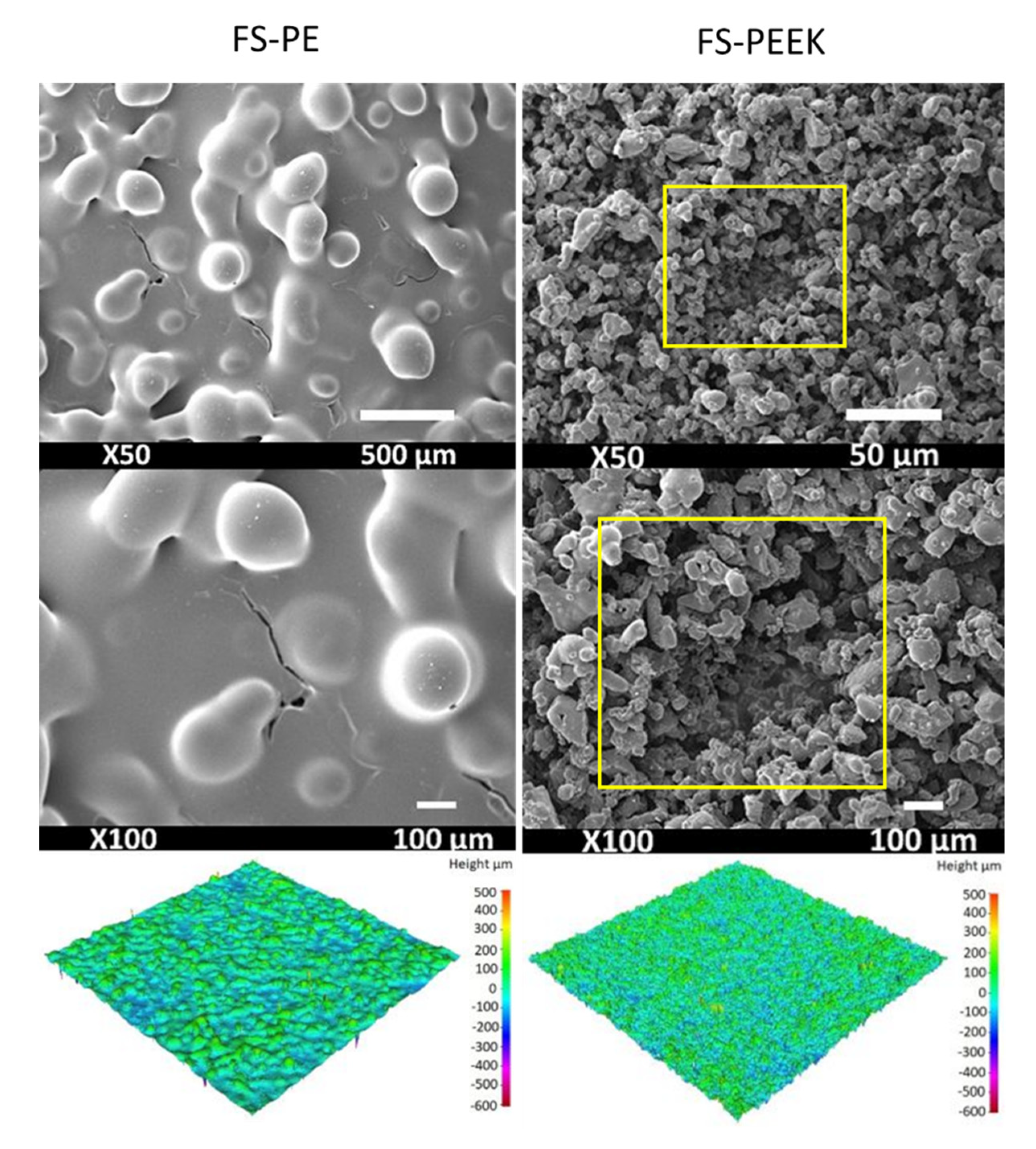
Figure 5 presents the fracture surface of FS-PE coating. The internal porosity was uniformly distributed in the structure with a pore size of ~1 µm. Meanwhile, Figure 6 shows SEM images of the coating surfaces and the coating topographies. The FS-PE coating revealed spherical particles which were not fully molten within the molten matrix, with some level of surface porosity. The topography of the FS-PE coating varied from smooth, fully molten to spherical shaped semi-molten particles. Additionally, the coating surface has less open porosity due to the post-heating during flame-spray processing. The surface of the FS-PEEK coating (Figure 6) showed semi-molten particles built up and porosity between the particle splats. The surface topography and the roughness values showed a smoother surface than that of the FS-PE coating due to the finer particle morphology. The surface of the CS-PEEK coating (Figure 6), instead, showed that the particles were similar to the feedstock powder because of the low processing temperature, and the surface-hammering effect of the next coming particles was missing [67]. The corresponding surface topography and areal roughness values showed that CS-PEEK had the smoothest surface in this study. All coatings had porous structures, which is the main aim when developing the features of the coating structure to produce SLIPS. As has been reported, the preferred structure is the micro–nano-structure; it can perform better in anti-icing applications than only the nanostructure because it can work as an oil reservoir and reduce lubricant loss during the icing–deicing process [83].
Table 5 presents the areal surface roughness (Sa) of the coatings before and after cyclic icing–deicing tests. FS-PE has the highest roughness value before icing. In the production of this coating, the optimized process parameters were used, resulting in this roughness together with its suitable porosity. The surface roughness of the coatings follows the particle size used in the different cases. LDPE powder had the largest particle size and highest surface roughness in the coatings, whereas PEEK powder was finer; the finest one was used with the cold-spray process, which led to the lowest roughness, as well.
3.3. Ice Adhesion of the Coatings
An icephobic surface, in general, can be defined as the ability of a solid surface to expel ice or prohibit ice formation [8]. Ice adhesion strength is another substantial parameter that has been extensively used to assess icephobic surface properties. It indicates how easily the ice can be removed from the surface [8]. In the centrifugal ice adhesion test method, a surface with ice adhesion strength at or below 100 kPa is deemed an icephobic surface [84], and with ice adhesion strength below 50 kPa is considered a low-ice-adhesion surface [85]. If the ice adhesion is less than 10 kPa, the surface is considered an extremely low-ice-adhesion surface. Figure 7 shows the ice adhesion strength values after the first icing–deicing cyclic test for the porous FS-PE, FS-PEEK, and CS-PEEK coatings and the FS-PE SLIPS, FS-PEEK SLIPS, and CS-PEEK SLIPS, in addition to the reference Teflon tape (TT) samples. All the SLIPS can be considered as icephobic surfaces (ice adhesion strength below 100 kPa) [86] according to the used ice accretion method and ice adhesion test, with values of 22 ± 6 kPa, 76 ± 31 kPa, and 71 ± 19 kPa for FS-PE SLIPS, FS-PEEK SLIPS, and CS-PEEK SLIPS, respectively, and 45 ± 7 kPa for the TT reference sample. Meanwhile, FS-PE SLIPS had the lowest ice adhesion value at 22 kPa. This is similar to the value accomplished previously in our earlier study [63], and it can be deemed as a low-ice-adhesion surface. Compared to the non-SLIPS coatings, the values of ice adhesion were 104 ± 23 kPa, 344 ± 88 kPa, and 348 ± 27 kPa for FS-PE, FS-PEEK, and CS-PEEK, respectively. It can be noticed that FS-PE SLIPS and CS-PEEK SLIPS performed five times better than the FS-PE and CS-PEEK coatings, and FS-PEEK SLIPS performed more than four times better than the FS-PEEK coating. This reveals the importance of the lubricant in the structure to reduce the ice adhesion strength [34,63,81,87,88,89,90]. It can be noted that the presence of oil in the structure can dramatically reduce the ice adhesion strength compared to the same structure without oil, regardless of the oil amount and viscosity [90]. The low ice adhesion of the SLIPS compared to the coatings without oil can be attributed to the extra slippage the infused oil brings between the rough structure and the deposited ice layer, which reduced the bond between them [91,92].
Four cycles in the cyclic icing–deicing tests for the SLIPS samples were performed to investigate the surface durability and stability of icephobic behavior. This is the first time we have studied the cyclic icing behavior of thermally sprayed SLIPS as an indicator of their durability. It is important to have durable solutions to increase the sustainability and long-standing behavior of icephobic surfaces. Figure 8 shows the ice adhesion values for the four cyclic icing–deicing tests, where the numbers 1, 2, 3, and 4 refer to the cycles’ numbers. The lowest ice adhesion of the SLIPS was achieved with the FS-PE SLIPS, and it can be noticed that the ice adhesion values stayed in a close range during the icing–deicing cycles. The unique microstructure of FS-PE which consisted of some open micro-porosity in the surface, as shown in Figure 6, and internal equally distributed nano-porosity, as shown in Figure 5 allowed it to reserve the oil and maintain it during icing–deicing tests and preserve the icephobic behavior at the same level (~20–30 kPa), indicating its icing durability. The ice adhesion values of FS-PEEK SLIPS can be influenced by the oil effect on the values; in this case, they started with 76 ± 31 kPa after the first cycle and increased after each cycle up to 307 ± 101 kPa after the fourth icing–deicing test. This can be explained by the highly open porosity of the structure, which can relatively decrease the oil amount during the cyclic icing–deicing test [93]. For CS-PEEK SLIPS, after the first cyclic icing–deicing test, the ice adhesion was 71 ± 19 kPa and increased after each cycle to reach 201 ± 94 kPa after the fourth cycle. The coating microstructure, as shown in Figure 4, was uniform, with equally distributed porosity and with open porosity on the surface, as shown in Figure 6. The structure can hold the lubricant, and loses it gradually with the cyclic icing–deicing test [94].
The lubricity of the SLIPS came from the lubricating layer and the structure performed a critical role in retaining the lubricant in place and stabilizing it [95]. The lubricant can be locked inside the structure when the capillary forces govern the regime, and this can take place when the structure features are small enough [96]. Nano- and micro-scale structures are usually smaller than the capillary length of the infused lubricant and, therefore, the structure can retain the lubricant inside it [95]. When the SLIPS is subjected to shear forces, like in the centrifugal ice adhesion test, the lubricant layer may deplete with test repetition, and its thickness becomes smaller [97]. The anti-icing surface needs to survive a repeated icing–deicing process and shear forces, and lower ice adhesion strength can be achieved when the surface has excessed lubricant oil [45,46]. This was the case in the first cycle, and it kept lessening after each cycle, while the ice adhesion increased gradually. From a structure point of view, after the cyclic icing–deicing tests, the lubricant can deplete faster when the structure is at a micro-scale, and is locked effectively when the structure at a nano-scale, due to its sturdy capillary forces [21,98,99]. It has been reported that the closed-cell structure (such as FS-PE SLIPS) can retain the lubricant when subjected to shear force, while open-cell structures (such as FS-PEEK SLIPS and CS-PEEK SLIPS) retain a smaller amount of lubricant at the same shear force [100]. Although the ice adhesion strength values of FS-PEEK SLIPS and CS-PEEK SLIPS increased gradually during the cyclic icing–deicing tests, it was still lower than the coatings without oil; this is because the presence of oil in the structure, even in a small amount, was sufficient to decrease the bond between the ice and the structure [90]. Figure 9 shows the FTIR spectra results for the silicon oil, porous coatings, and SLIPS before and after the cyclic icing–deicing test. The oil present in the SLIPS structure can be noticed before and after icing via the yellow area highlighted in Figure 9, matching the silicone oil spectra. This can explain the lower ice adhesion values of SLIPS compared to their corresponding porous coatings, even after cyclic icing–deicing, and shows their potential as icephobic surfaces. However, more optimization is needed to increase their icing durability.
3.4. Wetting Properties of the Coatings
Wettability is generally a recognized parameter that can be linked with ice adhesion strength. Surfaces with high contact angles can have low ice adhesion strengths because of low surface energy [81,101,102]. According to Wenzel’s regime for water contacting rough surfaces, water droplets infiltrate through surface roughness, where they are pinned and cannot roll off [103]. On the other hand, in the case of the Cassie–Baxter regime, air trapped inside the rough surface structure works to decrease the contact area of the liquid and solid surfaces, and enhances the water droplets’ repellency [103]. Figure 10 illustrates the shapes of the water droplets on the porous coatings and their corresponding SLIPS before and after the cyclic icing–deicing test. The water contact angles can vary depending on surface roughness, surface history (before or after cyclic icing–deicing test), and the droplet shape if there is lubricant oil present, creating wetting ridges [104].
Figure 11 presents the wetting behavior of the porous coatings and the SLIPS before and after cyclic icing–deicing tests. The static or apparent WCA for the porous coatings before cyclic icing–deicing tests was 80° ± 7° for FS-PE, 123° ± 4° for FS-PEEK, and 121° ± 5° for CS-PEEK. Surface roughness can affect the values of the WCA, and direct comparison between different surfaces is possible when these surfaces have similar surface roughness [105]. After the cyclic icing–deicing test the values were 86° ± 8° for FS-PE and 121° ± 3° for FS-PEEK, and unfortunately, the CS-PEEK coating detached from the substrate after the cyclic icing–deicing test, so no values were obtained. The apparent WCAs for the SLIPS before the icing–deicing cyclic test was 72° ± 3° for FS-PE SLIPS, 74° ± 2° for FS-PEEK SLIPS, and 84° ± 4° for CS-PEEK SLIPS. When a water droplet was deposited on SLIPS, it can be encapsulated with the lubricant, or the lubricant forms wetting ridges according to the spreading coefficient between the lubricant and the water in the presence of the surrounding air. If S > 0, the oil will cloak the water droplet, while if S < 0, it implies that the water droplet rests on top of the oil [104,106]. The observed necking near the baseline of the water droplet on the SLIPS surface, as shown in Figure 10, implies that the point where the convex droplet shape changed to concave is congruent with the height of the circular ridge of oil that raised up to satisfy the equilibrium state with the interfacial forces at the deviated region [104,107]. The apparent WCAs for the SLIPS after the cyclic icing–deicing test were higher than before the cyclic icing–deicing test, with values of 98° ± 4° for FS-PE SLIPS, 119° ± 4° for FS-PEEK SLIPS, and 109° ± 5° for CS-PEEK SLIPS; this is because the droplet-surrounding wetting ridge and the cloaking oil film affected the measurements.
The water droplets were pinned in the roll-off WCA test with FS-PE, FS-PEEK, and CS-PEEK porous coatings before and after the icing tests. The coating surfaces were rough, and in this case, the droplet–surface–air interaction followed Wenzel state [103], whereby the water droplets penetrate and fill the surface pores and are interlocked [8]. Meanwhile, the roll-off WCA values for the SLIPS samples before the cyclic icing–deicing test were 9° ± 2° for FS-PE SLIPS, 16° ± 4° for FS-PEEK, and 7° ± 3° for CS-PEEK, with hysteresis of 1.7, 1.7, and 2.6, respectively. The lubricant cloaking had a positive effect on easily rolling off the water droplets and preventing them from pinning [107]. The low hysteresis indicates the ease of droplet shedding owing to the presence of the low-surface-energy surface lubricant film [90]. For the SLIPS samples after the cyclic icing–deicing test, the droplets were pinned with FS-PE SLIPS, and they were 18° ± 2° for FS-PEEK SLIPS with a hysteresis of 1.5, and 17° ± 4° for CS-PEEK SLIPS with a hysteresis of 6.3. After the cyclic icing–deicing test, the oil content in the surface roughness decreased [108], as can be seen from the images of SLIPS after the icing tests in Figure 10, due to the mechanical effect of the ice accretion and the centrifugal ice adhesion test. It is worth mentioning that only an amount of the surface oil layer may decrease; the SLIPS structures were successful in maintaining the oil, even after the cyclic icing–deicing test, as demonstrated in Figure 9, for the SLIPS FTIR spectra before and after icing compared to silicon oil and the porous coating spectra. In that case, the deposited water droplet can penetrate inside the surface roughness (Wenzel’s state); moreover, it can hinder the droplet mobility, compared to the SLIPS before icing, for which the low-surface-energy oil enhances the water droplet movement and prevents it from pinning. Contact angle hysteresis was the difference between the advanced and the receding angles, and it was affected by the surface roughness. It was used as an indication of how easily the droplet can slide off from the surface [109]. Low hysteresis on the rough surface indicated that the wetting followed the Cassie–Baxter mode, where the air was trapped inside the surface porosity and prevented the droplet from penetrating, while higher hysteresis suggested wettability dominated by a transition mode between Wenzel and Cassie–Baxter, where the droplet partially penetrated but was still able to roll-off [110].
During ice accretion, the supercooled water droplets were deposited on the rough coating surface, and they could go between the peaks and valleys. The type of ice was mixed glaze, which was not too dry or too wet, but still had some water content [111,112]. After resting the samples for ~16 h in a −10 °C cold room, the ice was fully frozen and completely solidified. This can cause an expansion in ice volume and can cause ice cracks and the running of back ice [112]. These changes can affect the coating structure, whereby ice volume expansion can bring internal stresses to the surface roughness because of the mismatched thermal expansion between the ice and the polymer [113]. During CAT, the samples experience shear forces all along the rotation. The combination of the internal stresses and the shear forces that the samples underwent can cause surface damage. Figure 12 shows the coating surfaces and the topography after the icing–deicing test. For the porous FS-PE, the coating surface showed cracks, and meanwhile, the Sa values after the icing test dropped from 65 µm to 47 µm. The mechanical effect of the shear forces during CAT have made the surface smoother. Failures were not detected in the SLIPS, which supported the protective effect of lubricant and increased the durability of the structures. On the other hand, the presence of the cracks on the structure (Figure 12) works as extra micro-pores on the surface that trap air inside, which worked to increase the apparent WCA after icing.
For the FS-PEEK coating, the mechanical effect of the internal stresses is caused by the expansion of the ice inside the surface porosity after the ice accretion process. The centrifugal shear forces caused during the ice adhesion test can cause cohesive failure and delaminate parts of the coating, as marked with the yellow squares in Figure 12. This increased the surface roughness (Sa) from 53 µm to 56 µm, where more peaks and valleys were created, in addition to an increase in the surface waviness. It is worth mentioning that these porous coatings by themselves (without lubricant) were not designed to be used for anti-icing applications; however, they were studied for a comparison between the coatings and their SLIPS, and to discover the oil-presence effect on the surface properties and icephobic behavior of the SLIPS.
4. Conclusions
In this study, flame-sprayed LDPE coatings for icephobic SLIPS were produced based on previous work [63], and the durability of the coating in cyclic icing–deicing tests was examined. Additionally, FS and CS process parameters were optimized to produce porous PEEK coatings for SLIPS that have the potential to serve as icephobic surfaces. We explained how adding lubricant to the porous surfaces to produce SLIPS can reduce the ice adhesion values for FS-PE, FS-PEEK, and CS-PEEK coatings; this was particularly true for the FS-PE SLIPS, which showed the lowest ice adhesion value of 22 ± 6 kPa and maintained the value for a close range after the cyclic icing–deicing test, indicating the icing durability of the SLIPS. Future work will focus on further optimization of the PEEK coatings by means of their structures, and studies of environmental durability (e.g., in UV exposure, and changing surrounding temperature and mechanical stresses) for thermally sprayed SLIPS.
Author Contributions
Conceptualization, R.K. and H.K.; investigation R.K.; analysis R.K.; writing R.K.; review and editing H.K.; supervision H.K.; funding acquisition H.K. All authors have read and agreed to the published version of the manuscript.
Funding
This research was funded by the Academy of Finland project “Thermally Sprayed slippery liquid-infused porous surface-towards durable anti-icing coatings” (TS-SLIPS).
Institutional Review Board Statement
Not applicable.
Informed Consent Statement
Not applicable.
Data Availability Statement
Data from this study are available upon request from the corresponding author.
Acknowledgments
The authors would like to thank Jarkko Lehti and Anssi Metsähonkala of Tampere University, Thermal Spray Center Finland (TSCF), Tampere, Finland, for spraying the coatings; Jari Oja and Niklas Kandelin of Tampere University for their assistance in the icing laboratory at Tampere University; and Alexander Efimov of Tampere University for assisting in the FTIR tests. The SEM work made use of the Tampere Microscope Center facilities at Tampere University, Tampere, Finland.
Conflicts of Interest
The authors declare no conflict of interest. The funders had no role in the design of the study; in the collection, analyses, or interpretation of data; in the writing of the manuscript; or in the decision to publish the results.
References
- Fikke, S.M.; Kristjánsson, J.E.; Kringlebotn Nygaard, B.E. Modern meteorology and atmospheric icing. Atmos. Icing Power Netw. 2008, 1–29. [Google Scholar] [CrossRef]
- Carriveau, R.; Edrisy, A.; Cadieux, P.; Mailloux, R. Ice adhesion issues in renewable energy infrastructure. J. Adh. Sci. Technol. 2012, 26, 447–461. [Google Scholar] [CrossRef]
- Wang, Y.; Zhang, G.; Tian, Z.; Qiu, R.; Liu, Z. An Online Thermal Deicing Method for Urban Rail Transit Catenary. IEEE Trans. Transp. Electrif. 2021, 7, 870–882. [Google Scholar] [CrossRef]
- Shu, L.; Li, H.; Hu, Q.; Jiang, X.; Qiu, G.; McClure, G.; Yang, H. Study of ice accretion feature and power characteristics of wind turbines at natural icing environment. Cold Reg. Sci. Technol. 2018, 147, 45–54. [Google Scholar] [CrossRef]
- Rashid, T.; Abbas Khawaja, H.; Edvardsen, K. Review of marine icing and anti-/de-icing systems. J. Mar. Eng. Technol. 2016, 15, 79–87. [Google Scholar] [CrossRef]
- Cao, Y.; Tan, W.; Wu, Z. Aircraft icing: An ongoing threat to aviation safety. Aerosp. Sci. Technol. 2018, 75, 353–385. [Google Scholar] [CrossRef]
- Kim, P.; Wong, T.S.; Alvarenga, J.; Kreder, M.J.; Adorno-Martinez, W.E.; Aizenberg, J. Liquid-infused nanostructured surfaces with extreme anti-ice and anti-frost performance. ACS Nano 2012, 6, 6569–6577. [Google Scholar] [CrossRef]
- Shen, Y.; Wu, X.; Tao, J.; Zhu, C.; Lai, Y.; Chen, Z. Icephobic materials: Fundamentals, performance evaluation, and applications. Prog. Mater. Sci. 2019, 103, 509–557. [Google Scholar] [CrossRef]
- Huang, X.; Tepylo, N.; Pommier-Budinger, V.; Budinger, M.; Bonaccurso, E.; Villedieu, P.; Bennani, L. A survey of icephobic coatings and their potential use in a hybrid coating/active ice protection system for aerospace applications. Prog. Aerosp. Sci. 2019, 105, 74–97. [Google Scholar] [CrossRef] [Green Version]
- Sojoudi, H.; Wang, M.; Boscher, N.D.; McKinley, G.H.; Gleason, K.K. Durable and scalable icephobic surfaces: Similarities and distinctions from superhydrophobic surfaces. Soft Matter 2016, 12, 1938–1963. [Google Scholar] [CrossRef] [Green Version]
- Wang, T.; Zheng, Y.; Raji, A.R.O.; Li, Y.; Sikkema, W.K.A.; Tour, J.M. Passive Anti-Icing and Active Deicing Films. ACS Appl. Mater. Interfaces 2016, 8, 14169–14173. [Google Scholar] [CrossRef] [PubMed]
- Parent, O.; Ilinca, A. Anti-icing and de-icing techniques for wind turbines: Critical review. Cold Reg. Sci. Technol. 2011, 65, 88–96. [Google Scholar] [CrossRef]
- Han, S.; Wei, H.; Han, L.; Li, Q. Durability and Electrical Conductivity of Carbon Fiber Cloth/Ethylene Propylene Diene Monomer Rubber Composite for Active Deicing and Snow Melting. Polymers 2019, 11, 2051. [Google Scholar] [CrossRef] [PubMed] [Green Version]
- Yang, J.; Zhu, X.; Li, L.; Ling, H.; Zhou, P.; Cheng, Z.; Su, A.; Du, Y. Prefabricated Flexible Conductive Composite Overlay for Active Deicing and Snow Melting. J. Mater. Civ. Eng. 2018, 30, 04018283. [Google Scholar] [CrossRef]
- Daniliuk, V.; Xu, Y.; Liu, R.; He, T.; Wang, X. Ultrasonic de-icing of wind turbine blades: Performance comparison of perspective transducers. Renew. Energy 2020, 145, 2005–2018. [Google Scholar] [CrossRef]
- Daniliuk, V.; Pamfilov, E.; Daniliuk, A.; Xu, Y. Feasibility Study of Ultrasonic De-Icing Technique for Aircraft Wing Ice Protection. Int. Conf. Aviamechanical Eng. Transp. 2019, 188, 77–82. [Google Scholar] [CrossRef] [Green Version]
- Wang, Y.; Xu, Y.; Lei, Y. An effect assessment and prediction method of ultrasonic de-icing for composite wind turbine blades. Renew. Energy 2018, 118, 1015–1023. [Google Scholar] [CrossRef]
- Zhou, F.; Zhu, J.; An, N.; Wang, C.; Liu, J.; Long, L. The anti-icing and deicing robot system for electricity transmission line based on external excitation resonant. IEEJ Trans. Electr. Electron. Eng. 2020, 15, 593–600. [Google Scholar] [CrossRef]
- Huttunen-Saarivirta, E.; Kuokkala, V.T.; Kokkonen, J.; Paajanen, H. Corrosion effects of runway de-icing chemicals on aircraft alloys and coatings. Mater. Chem. Phys. 2011, 126, 138–151. [Google Scholar] [CrossRef]
- Muthumani, A.; Fay, L.; Akin, M.; Wang, S.; Gong, J.; Shi, X. Correlating lab and field tests for evaluation of deicing and anti-icing chemicals: A review of potential approaches. Cold Reg. Sci. Technol. 2014, 97, 21–32. [Google Scholar] [CrossRef]
- Kreder, M.J.; Alvarenga, J.; Kim, P.; Aizenberg, J. Design of anti-icing surfaces: Smooth, textured or slippery? Nat. Rev. Mater. 2016, 1, 1–15. [Google Scholar] [CrossRef]
- Cao, L.; Jones, A.K.; Sikka, V.K.; Wu, J.; Gao, D. Anti-Icing superhydrophobic coatings. Langmuir 2009, 25, 12444–12448. [Google Scholar] [CrossRef]
- Laturkar, S.V.; Mahanwar, P.A. Superhydrophobic coatings using nanomaterials for anti-frost applications—Review. Nanosyst. Phys. Chem. Math. 2016, 7, 650–656. [Google Scholar] [CrossRef] [Green Version]
- Pan, S.; Wang, N.; Xiong, D.; Deng, Y.; Shi, Y. Fabrication of superhydrophobic coating via spraying method and its applications in anti-icing and anti-corrosion. Appl. Surf. Sci. 2016, 389, 547–553. [Google Scholar] [CrossRef]
- Wu, X.; Silberschmidt, V.V.; Hu, Z.T.; Chen, Z. When superhydrophobic coatings are icephobic: Role of surface topology. Surf. Coat. Technol. 2019, 358, 207–214. [Google Scholar] [CrossRef] [Green Version]
- Ensikat, H.J.; Ditsche-Kuru, P.; Neinhuis, C.; Barthlott, W. Superhydrophobicity in perfection: The outstanding properties of the lotus leaf. Beilstein J. Nanotechnol. 2011, 2, 152–161. [Google Scholar] [CrossRef] [Green Version]
- Barthlott, W.; Neinhuis, C. Purity of the sacred lotus, or escape from contamination in biological surfaces. Planta 1997, 202, 1–8. [Google Scholar] [CrossRef]
- Singh, A.V.; Rahman, A.; Sudhir Kumar, N.V.G.; Aditi, A.S.; Galluzzi, M.; Bovio, S.; Barozzi, S.; Montani, E.; Parazzoli, D. Bio-inspired approaches to design smart fabrics. Mater. Des. 2012, 36, 829–839. [Google Scholar] [CrossRef]
- Wang, Z.; Li, Q.; She, Z.; Chen, F.; Li, L. Low-cost and large-scale fabrication method for an environmentally-friendly superhydrophobic coating on magnesium alloy. J. Mater. Chem. 2012, 22, 4097–4105. [Google Scholar] [CrossRef]
- Zheng, S.; Li, C.; Fu, Q.; Hu, W.; Xiang, T.; Wang, Q.; Du, M.; Liu, X.; Chen, Z. Development of stable superhydrophobic coatings on aluminum surface for corrosion-resistant, self-cleaning, and anti-icing applications. Mater. Des. 2016, 93, 261–270. [Google Scholar] [CrossRef]
- Wong, T.S.; Kang, S.H.; Tang, S.K.Y.; Smythe, E.J.; Hatton, B.D.; Grinthal, A.; Aizenberg, J. Bioinspired self-repairing slippery surfaces with pressure-stable omniphobicity. Nature 2011, 477, 443–447. [Google Scholar] [CrossRef] [PubMed]
- Manoharan, K.; Bhattacharya, S. Superhydrophobic surfaces review: Functional application, fabrication techniques and limitations. J. Micromanuf. 2019, 2, 59–78. [Google Scholar] [CrossRef]
- Farhadi, S.; Farzaneh, M.; Kulinich, S.A. Anti-icing performance of superhydrophobic surfaces. Appl. Surf. Sci. 2011, 257, 6264–6269. [Google Scholar] [CrossRef]
- Liu, Y.; Tian, Y.; Chen, J.; Gu, H.; Liu, J.; Wang, R.; Zhang, B.; Zhang, H.; Zhang, Q. Design and preparation of bioinspired slippery liquid-infused porous surfaces with anti-icing performance via delayed phase inversion process. Colloids Surf. A Physicochem. Eng. Asp. 2020, 588, 124384. [Google Scholar] [CrossRef]
- Juuti, P.; Haapanen, J.; Stenroos, C.; Niemelä-Anttonen, H.; Harra, J.; Koivuluoto, H.; Teisala, H.; Lahti, J.; Tuominen, M.; Kuusipalo, J.; et al. Achieving a slippery, liquid-infused porous surface with anti-icing properties by direct deposition of flame synthesized aerosol nanoparticles on a thermally fragile substrate. Appl. Phys. Lett. 2017, 110, 161603. [Google Scholar] [CrossRef]
- Wilson, P.W.; Lu, W.; Xu, H.; Kim, P.; Kreder, M.J.; Alvarenga, J.; Aizenberg, J. Inhibition of ice nucleation by slippery liquid-infused porous surfaces (SLIPS). Phys. Chem. Chem. Phys. 2013, 15, 581–585. [Google Scholar] [CrossRef]
- Zhang, M.; Chen, R.; Liu, Q.; Liu, J.; Yu, J.; Song, D.; Liu, P.; Gao, L.; Wang, J. Long-Term Stability of a Liquid-Infused Coating with Anti-Corrosion and Anti-Icing Potentials on Al Alloy. ChemElectroChem 2019, 6, 3911–3919. [Google Scholar] [CrossRef]
- Zhang, M.; Yu, J.; Chen, R.; Liu, Q.; Liu, J.; Song, D.; Liu, P.; Gao, L.; Wang, J. Highly transparent and robust slippery lubricant-infused porous surfaces with anti-icing and anti-fouling performances. J. Alloys Compd. 2019, 803, 51–60. [Google Scholar] [CrossRef]
- Wang, Y.; Zhang, H.; Liu, X.; Zhou, Z. Slippery liquid-infused substrates: A versatile preparation, unique anti-wetting and drag-reduction effect on water. J. Mater. Chem. A 2016, 4, 2524–2529. [Google Scholar] [CrossRef]
- Huang, C.; Guo, Z. Fabrications and Applications of Slippery Liquid-infused Porous Surfaces Inspired from Nature: A Review. J. Bionic Eng. 2019, 16, 769–793. [Google Scholar] [CrossRef]
- Latthe, S.S.; Sutar, R.S.; Bhosale, A.K.; Nagappan, S.; Ha, C.S.; Sadasivuni, K.K.; Liu, S.; Xing, R. Recent developments in air-trapped superhydrophobic and liquid-infused slippery surfaces for anti-icing application. Prog. Org. Coat. 2019, 137, 105373. [Google Scholar] [CrossRef]
- Long, Y.; Yin, X.; Mu, P.; Wang, Q.; Hu, J.; Li, J. Slippery liquid-infused porous surface (SLIPS) with superior liquid repellency, anti-corrosion, anti-icing and intensified durability for protecting substrates. Chem. Eng. J. 2020, 401, 126137. [Google Scholar] [CrossRef]
- Yuan, Y.; Wang, L.; Liu, G.; Liao, R. Fabrication of ultralow ice-adhesion slippery liquid infused porous surfaces on aluminum alloy (7075-t651). Coatings 2020, 10, 1025. [Google Scholar] [CrossRef]
- Liu, C.; Li, Y.; Lu, C.; Liu, Y.; Feng, S.; Liu, Y. Robust Slippery Liquid-Infused Porous Network Surfaces for Enhanced Anti-icing/Deicing Performance. ACS Appl. Mater. Interfaces 2020, 12, 25471–25477. [Google Scholar] [CrossRef] [PubMed]
- Liu, Q.; Yang, Y.; Huang, M.; Zhou, Y.; Liu, Y.; Liang, X. Durability of a lubricant-infused Electrospray Silicon Rubber surface as an anti-icing coating. Appl. Surf. Sci. 2015, 346, 68–76. [Google Scholar] [CrossRef]
- Subramanyam, S.B.; Rykaczewski, K.; Varanasi, K.K. Ice adhesion on lubricant-impregnated textured surfaces. Langmuir 2013, 29, 13414–13418. [Google Scholar] [CrossRef]
- Li, J.; Ueda, E.; Paulssen, D.; Levkin, P.A. Slippery Lubricant-Infused Surfaces: Properties and Emerging Applications. Adv. Funct. Mater. 2019, 29, 1–13. [Google Scholar] [CrossRef] [Green Version]
- Coady, M.J.; Wood, M.; Wallace, G.Q.; Nielsen, K.E.; Kietzig, A.M.; Lagugné-Labarthet, F.; Ragogna, P.J. Icephobic Behavior of UV-Cured Polymer Networks Incorporated into Slippery Lubricant-Infused Porous Surfaces: Improving SLIPS Durability. ACS Appl. Mater. Interfaces 2018, 10, 2890–2896. [Google Scholar] [CrossRef]
- Kim, J.H.; Kim, M.J.; Lee, B.; Chun, J.M.; Patil, V.; Kim, Y.S. Durable ice-lubricating surfaces based on polydimethylsiloxane embedded silicone oil infused silica aerogel. Appl. Surf. Sci. 2020, 512, 145728. [Google Scholar] [CrossRef]
- Zhuo, Y.; Wang, F.; Xiao, S.; He, J.; Zhang, Z. One-Step Fabrication of Bioinspired Lubricant-Regenerable Icephobic Slippery Liquid-Infused Porous Surfaces. ACS Omega 2018, 3, 10139–10144. [Google Scholar] [CrossRef]
- Fender, T.D. Thermal spray high performance polymer coatings. Mater. Technol. 1996, 11, 16–20. [Google Scholar] [CrossRef]
- Ivosevic, M.; Coguill, S.L.; Galbraith, S.L. Polymer thermal spraying: A novel coating process. Proc. Int. Therm. Spray Conf. 2009, 1078–1083. [Google Scholar] [CrossRef]
- Petrovicova, E.; Schadler, L.S. Thermal spraying of polymers. Int. Mater. Rev. 2002, 47, 169–190. [Google Scholar] [CrossRef]
- Donadei, V.; Koivuluoto, H.; Sarlin, E.; Vuoristo, P. Icephobic Behaviour and Thermal Stability of Flame-Sprayed Polyethylene Coating: The Effect of Process Parameters. J. Therm. Spray Technol. 2020, 29, 241–254. [Google Scholar] [CrossRef] [Green Version]
- Koivuluoto, H.; Hartikainen, E.; Niemelä-Anttonen, H. Thermally sprayed coatings: Novel surface engineering strategy towards icephobic solutions. Materials 2020, 13, 1434. [Google Scholar] [CrossRef] [PubMed] [Green Version]
- Koivuluoto, H.; Stenroos, C.; Kylmälahti, M.; Apostol, M.; Kiilakoski, J.; Vuoristo, P. Anti-icing Behavior of Thermally Sprayed Polymer Coatings. J. Therm. Spray Technol. 2017, 26, 150–160. [Google Scholar] [CrossRef]
- Donadei, V.; Koivuluoto, H.; Sarlin, E.; Vuoristo, P. Lubricated icephobic coatings prepared by flame spraying with hybrid feedstock injection. Surf. Coat. Technol. 2020, 403, 126396. [Google Scholar] [CrossRef]
- Rezvani Rad, M.; Mohammadian Bajgiran, M.; Moreau, C.; McDonald, A. Fabrication of thermally sprayed coating systems for mitigation of ice accumulation in carbon steel pipes and prevention of pipe bursting. Surf. Coat. Technol. 2020, 397, 126013. [Google Scholar] [CrossRef]
- Mora, J.; García, P.; Muelas, R.; Agüero, A. Hard quasicrystalline coatings deposited by hvof thermal spray to reduce ice accretion in aero-structures components. Coatings 2020, 10, 290. [Google Scholar] [CrossRef] [Green Version]
- Xi, N.; Liu, Y.; Zhang, X.; Liu, N.; Fu, H.; Hang, Z.; Yang, G.; Chen, H.; Gao, W. Steady anti-icing coatings on weathering steel fabricated by HVOF spraying. Appl. Surf. Sci. 2018, 444, 757–762. [Google Scholar] [CrossRef]
- Liu, J.; Wang, J.; Memon, H.; Fu, Y.; Barman, T.; Choi, K.S.; Hou, X. Hydrophobic/icephobic coatings based on thermal sprayed metallic layers with subsequent surface functionalization. Surf. Coat. Technol. 2019, 357, 267–272. [Google Scholar] [CrossRef]
- Sharifi, N.; Dolatabadi, A.; Pugh, M.; Moreau, C. Anti-icing performance and durability of suspension plasma sprayed TiO2 coatings. Cold Reg. Sci. Technol. 2019, 159, 1–12. [Google Scholar] [CrossRef]
- Niemelä-Anttonen, H.; Koivuluoto, H.; Kylmälahti, M.; Laakso, J.; Vuoristo, P. Thermally sprayed slippery and icephobic surfaces. Proc. Int. Therm. Spray Conf. 2018, 2018, 380–384. [Google Scholar]
- Espallargas, N. Introduction to thermal spray coatings. In Future Development of Thermal Spray Coatings; Woodhead Publishing: Cambridge, UK, 2015; pp. 1–13. [Google Scholar] [CrossRef]
- Tucker, R.C. Introduction to Thermal Spray Technology. Therm. Spray Technol. 2018, 5, 3–9. [Google Scholar] [CrossRef]
- AlMangour, B. Fundamentals of cold spray processing: Evolution and future perspectives. In Cold-Spray Coatings; Springer: Cham, Switzerland, 2018; pp. 3–24. [Google Scholar] [CrossRef]
- Maev, R.G.; Leshchynsky, V. Low-Pressure Cold Spray (LPCS); Cavaliere, P., Ed.; Springer International Publishing: Cham, Switzerland, 2017; ISBN 9783319671833. [Google Scholar]
- Bush, T.B.; Khalkhali, Z.; Champagne, V.; Schmidt, D.P.; Rothstein, J.P. Optimization of Cold Spray Deposition of High-Density Polyethylene Powders. J. Therm. Spray Technol. 2017, 26, 1548–1564. [Google Scholar] [CrossRef]
- Sanpo, N.; Tan, M.L.; Cheang, P.; Khor, K.A. Antibacterial property of cold-sprayed HA-Ag/PEEK coating. J. Therm. Spray Technol. 2009, 18, 10–15. [Google Scholar] [CrossRef]
- Xu, Y.; Hutchings, I.M. Cold spray deposition of thermoplastic powder. Surf. Coat. Technol. 2006, 201, 3044–3050. [Google Scholar] [CrossRef]
- Khalkhali, Z.; Rothstein, J.P. Characterization of the cold spray deposition of a wide variety of polymeric powders. Surf. Coat. Technol. 2020, 383, 125251. [Google Scholar] [CrossRef]
- Moridi, A.; Hassani-Gangaraj, S.M.; Guagliano, M.; Dao, M. Cold spray coating: Review of material systems and future perspectives. Surf. Eng. 2014, 30, 369–395. [Google Scholar] [CrossRef]
- Chebbi, A.; Stokes, J. Thermal spraying of bioactive polymer coatings for orthopaedic applications. J. Therm. Spray Technol. 2012, 21, 719–730. [Google Scholar] [CrossRef]
- Yin, S.; Suo, X.; Xie, Y.; Li, W.; Lupoi, R.; Liao, H. Effect of substrate temperature on interfacial bonding for cold spray of Ni onto Cu. J. Mater. Sci. 2015, 50, 7448–7457. [Google Scholar] [CrossRef]
- Xie, Y.; Planche, M.P.; Raoelison, R.; Liao, H.; Suo, X.; Hervé, P. Effect of Substrate Preheating on Adhesive Strength of SS 316L Cold Spray Coatings. J. Therm. Spray Technol. 2016, 25, 123–130. [Google Scholar] [CrossRef]
- Goldbaum, D.; Shockley, J.M.; Chromik, R.R.; Rezaeian, A.; Yue, S.; Legoux, J.G.; Irissou, E. The effect of deposition conditions on adhesion strength of Ti and Ti6Al4V cold spray splats. J. Therm. Spray Technol. 2012, 21, 288–303. [Google Scholar] [CrossRef]
- Watanabe, Y.; Yoshida, C.; Atsumi, K.; Yamada, M.; Fukumoto, M. Influence of Substrate Temperature on Adhesion Strength of Cold-Sprayed Coatings. J. Therm. Spray Technol. 2014, 24, 86–91. [Google Scholar] [CrossRef]
- Xie, Y.; Yin, S.; Chen, C.; Planche, M.P.; Liao, H.; Lupoi, R. New insights into the coating/substrate interfacial bonding mechanism in cold spray. Scr. Mater. 2016, 125, 1–4. [Google Scholar] [CrossRef]
- Peppou-Chapman, S.; Hong, J.K.; Waterhouse, A.; Neto, C. Life and death of liquid-infused surfaces: A review on the choice, analysis and fate of the infused liquid layer. Chem. Soc. Rev. 2020, 49, 3688–3715. [Google Scholar] [CrossRef] [PubMed]
- Koivuluoto, H.; Stenroos, C.; Ruohomaa, R.; Bolelli, G.; Lusvarghi, L.; Vuoristo, P. Research on icing behavior and ice adhe-sion testing of icephobic surfaces. In Proceedings of the 16th International Workshop on Atmospheric Icing of Structures (IWAIS), Uppsala, Sweden, 28 June–3 July 2015; pp. 1–14. [Google Scholar]
- Wei, C.; Jin, B.; Zhang, Q.; Zhan, X.; Chen, F. Anti-icing performance of super-wetting surfaces from icing-resistance to ice-phobic aspects: Robust hydrophobic or slippery surfaces. J. Alloys Compd. 2018, 765, 721–730. [Google Scholar] [CrossRef]
- Crawmer, D.E. Coating Structures, Properties, and Materials. Therm. Spray Technol. 2018, 5, 60–64. [Google Scholar] [CrossRef]
- Barthwal, S.; Lee, B.; Lim, S.H. Fabrication of robust and durable slippery anti-icing coating on textured superhydrophobic aluminum surfaces with infused silicone oil. Appl. Surf. Sci. 2019, 496, 143677. [Google Scholar] [CrossRef]
- Gupta, M.C.; Mulroney, A. Ice Adhesion and Anti-Icing Using Microtextured Surfaces. Ice Adhes. 2020, 389–415. [Google Scholar] [CrossRef]
- Rønneberg, S.; He, J.; Zhang, Z. The need for standards in low ice adhesion surface research: A critical review. J. Adhes. Sci. Technol. 2020, 34, 319–347. [Google Scholar] [CrossRef]
- Niemelä-Anttonen, H.; Koivuluoto, H.; Tuominen, M.; Teisala, H.; Juuti, P.; Haapanen, J.; Harra, J.; Stenroos, C.; Lahti, J.; Kuusipalo, J.; et al. Icephobicity of Slippery Liquid Infused Porous Surfaces under Multiple Freeze–Thaw and Ice Accretion–Detachment Cycles. Adv. Mater. Interfaces 2018, 5, 1–8. [Google Scholar] [CrossRef]
- Tetteh, E.; Loth, E. Reducing static and impact ice adhesion with a self-lubricating icephobic coating (SLIC). Coatings 2020, 10, 262. [Google Scholar] [CrossRef] [Green Version]
- Hanh, V.T.H.; Truong, M.X.; Nguyen, T.B. Anti-icing approach on flexible slippery microstructure thin-film. Cold Reg. Sci. Technol. 2021, 186, 103280. [Google Scholar] [CrossRef]
- Manna, U.; Lynn, D.M. Fabrication of liquid-infused surfaces using reactive polymer multilayers: Principles for manipulating the behaviors and mobilities of aqueous fluids on slippery liquid interfaces. Adv. Mater. 2015, 27, 3007–3012. [Google Scholar] [CrossRef]
- Yeong, Y.H.; Wang, C.; Wynne, K.J.; Gupta, M.C. Oil-infused superhydrophobic silicone material for low ice adhesion with long-term infusion stability. ACS Appl. Mater. Interfaces 2016, 8, 32050–32059. [Google Scholar] [CrossRef]
- Zhu, L.; Xue, J.; Wang, Y.; Chen, Q.; Ding, J.; Wang, Q. Ice-phobic coatings based on silicon-oil-infused polydimethylsiloxane. ACS Appl. Mater. Interfaces 2013, 5, 4053–4062. [Google Scholar] [CrossRef]
- Golovin, K.; Kobaku, S.P.R.; Lee, D.H.; DiLoreto, E.T.; Mabry, J.M.; Tuteja, A. Designing durable icephobic surfaces. Sci. Adv. 2016, 2, e1501496. [Google Scholar] [CrossRef] [Green Version]
- Zhang, J.; Liu, B.; Tian, Y.; Wang, F.; Chen, Q.; Zhang, F.; Qian, H.; Ma, L. Facile one-step method to fabricate a slippery lubricant-infused surface (lis) with self-replenishment properties for anti-icing applications. Coatings 2020, 10, 119. [Google Scholar] [CrossRef] [Green Version]
- Liu, G.; Yuan, Y.; Liao, R.; Wang, L.; Gao, X. Fabrication of a porous slippery icephobic surface and effect of lubricant viscosity on anti-icing properties and durability. Coatings 2020, 10, 896. [Google Scholar] [CrossRef]
- Chen, X.; Wen, G.; Guo, Z. What are the design principles, from the choice of lubricants and structures to the preparation method, for a stable slippery lubricant-infused porous surface? Mater. Horizons 2020, 7, 1697–1726. [Google Scholar] [CrossRef]
- De Gennes, P.; Brochard-Wyart, F.; Quere, D. Capillarity and Wetting Phenomena Drops, Bubbles, Pearls, Waves; Springer: New York, NY, USA, 2004. [Google Scholar]
- Kim, P.; Kreder, M.J.; Alvarenga, J.; Aizenberg, J. Hierarchical or not? Effect of the length scale and hierarchy of the surface roughness on omniphobicity of lubricant-infused substrates. Nano Lett. 2013, 13, 1793–1799. [Google Scholar] [CrossRef]
- Anand, S.; Paxson, A.T.; Dhiman, R.; Smith, J.D.; Varanasi, K.K. Enhanced condensation on lubricant-impregnated nanotextured surfaces. ACS Nano 2012, 6, 10122–10129. [Google Scholar] [CrossRef]
- Rykaczewski, K.; Anand, S.; Subramanyam, S.B.; Varanasi, K.K. Mechanism of frost formation on lubricant-impregnated surfaces. Langmuir 2013, 29, 5230–5238. [Google Scholar] [CrossRef]
- Vogel, N.; Belisle, R.A.; Hatton, B.; Wong, T.S.; Aizenberg, J. Transparency and damage tolerance of patternable omniphobic lubricated surfaces based on inverse colloidal monolayers. Nat. Commun. 2013, 4, 2176. [Google Scholar] [CrossRef] [Green Version]
- Van Oss, C.J.; Giese, R.F.; Wentzek, R.; Norris, J.; Chuvilin, E.M. Surface Tension Parameters of Ice Obtained From Contact Angle Data and From Positive and Negative Particle Adhesion to Advancing Freezing Fronts. J. Adhes. Sci. Technol. 1992, 6, 503–516. [Google Scholar] [CrossRef]
- Zou, M.; Beckford, S.; Wei, R.; Ellis, C.; Hatton, G.; Miller, M.A. Effects of surface roughness and energy on ice adhesion strength. Appl. Surf. Sci. 2011, 257, 3786–3792. [Google Scholar] [CrossRef]
- Bormashenko, E. General equation describing wetting of rough surfaces. J. Colloid Interface Sci. 2011, 360, 317–319. [Google Scholar] [CrossRef]
- Smith, J.D.; Dhiman, R.; Anand, S.; Reza-Garduno, E.; Cohen, R.E.; McKinley, G.H.; Varanasi, K.K. Droplet mobility on lubricant-impregnated surfaces. Soft Matter 2013, 9, 1772–1780. [Google Scholar] [CrossRef] [Green Version]
- Kubiak, K.J.; Wilson, M.C.T.; Mathia, T.G.; Carval, P. Wettability versus roughness of engineering surfaces. Wear 2011, 271, 523–528. [Google Scholar] [CrossRef] [Green Version]
- Villegas, M.; Zhang, Y.; Abu Jarad, N.; Soleymani, L.; Didar, T.F. Liquid-Infused Surfaces: A Review of Theory, Design, and Applications. ACS Nano 2019, 13, 8517–8536. [Google Scholar] [CrossRef]
- Schellenberger, F.; Xie, J.; Encinas, N.; Hardy, A.; Klapper, M.; Papadopoulos, P.; Butt, H.J.; Vollmer, D. Direct observation of drops on slippery lubricant-infused surfaces. Soft Matter 2015, 11, 7617–7626. [Google Scholar] [CrossRef] [Green Version]
- Boinovich, L.B.; Chulkova, E.V.; Emelyanenko, K.A.; Domantovsky, A.G.; Emelyanenko, A.M. The mechanisms of anti-icing properties degradation for slippery liquid-infused porous surfaces under shear stresses. J. Colloid Interface Sci. 2022, 609, 260–268. [Google Scholar] [CrossRef]
- Whyman, G.; Bormashenko, E.; Stein, T. The rigorous derivation of Young, Cassie-Baxter and Wenzel equations and the analysis of the contact angle hysteresis phenomenon. Chem. Phys. Lett. 2008, 450, 355–359. [Google Scholar] [CrossRef]
- Yoshimitsu, Z.; Nakajima, A.; Watanabe, T.; Hashimoto, K. Effects of surface structure on the hydrophobicity and sliding behavior of water droplets. Langmuir 2002, 18, 5818–5822. [Google Scholar] [CrossRef]
- Tattelman, P. An objective method for measuring surface ice accretion. J. Appl. Meteorol. 1982, 21, 599–612. [Google Scholar] [CrossRef] [Green Version]
- Stenroos, C. Properties of Icephobic Surfaces in Different Icing Conditions. Master’s Thesis, Tampere University, Tampere, Finland, 2015. [Google Scholar]
- Donadei, V.; Koivuluoto, H.; Sarlin, E.; Niemelä, H.; Varis, T.; Vuoristo, P. The effect of mechanical and thermal stresses on the performance of lubricated icephobic coatings during cyclic icing / deicing tests. Prog. Org. Coat. 2022, 163, 10661. [Google Scholar] [CrossRef]
Figure 1.
FS-PE, FS-PEEK and CS-PEEK coating surfaces before and after oil impregnation (SLIPS). Sample size is 30 × 40 mm.
Figure 1.
FS-PE, FS-PEEK and CS-PEEK coating surfaces before and after oil impregnation (SLIPS). Sample size is 30 × 40 mm.
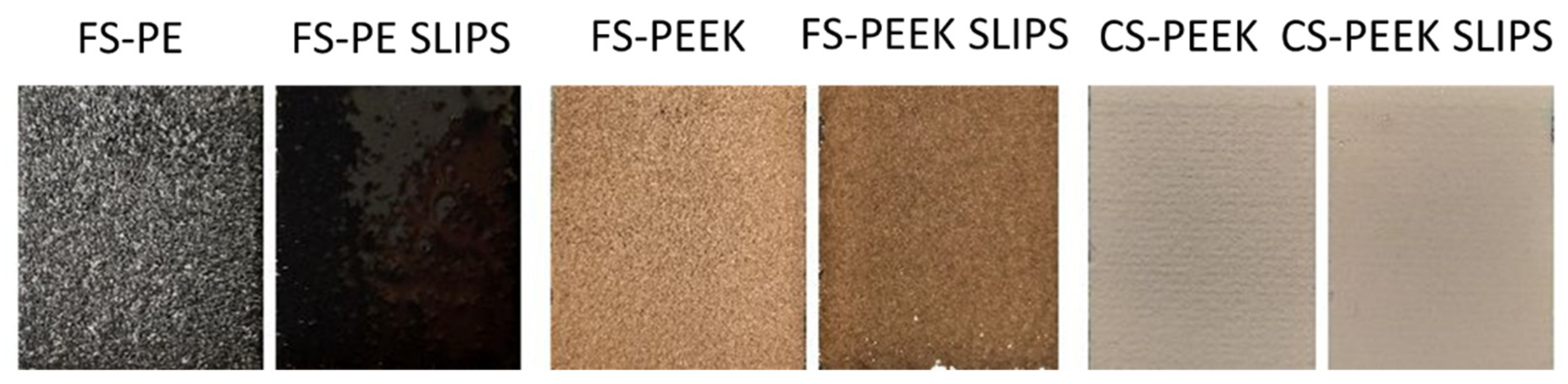
Figure 2.
Mixed-glaze ice accreted on the samples in IWiT for CAT testing.
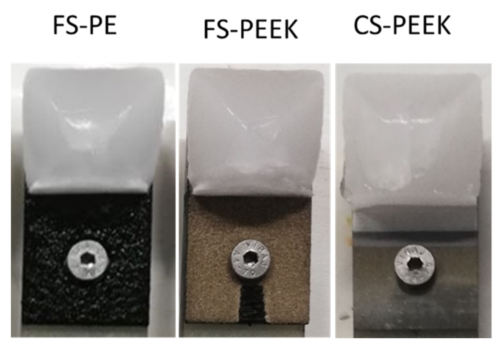
Figure 3.
SEM images of LDPE and PEEK feedstock powders and corresponding particle size distributions.
Figure 3.
SEM images of LDPE and PEEK feedstock powders and corresponding particle size distributions.
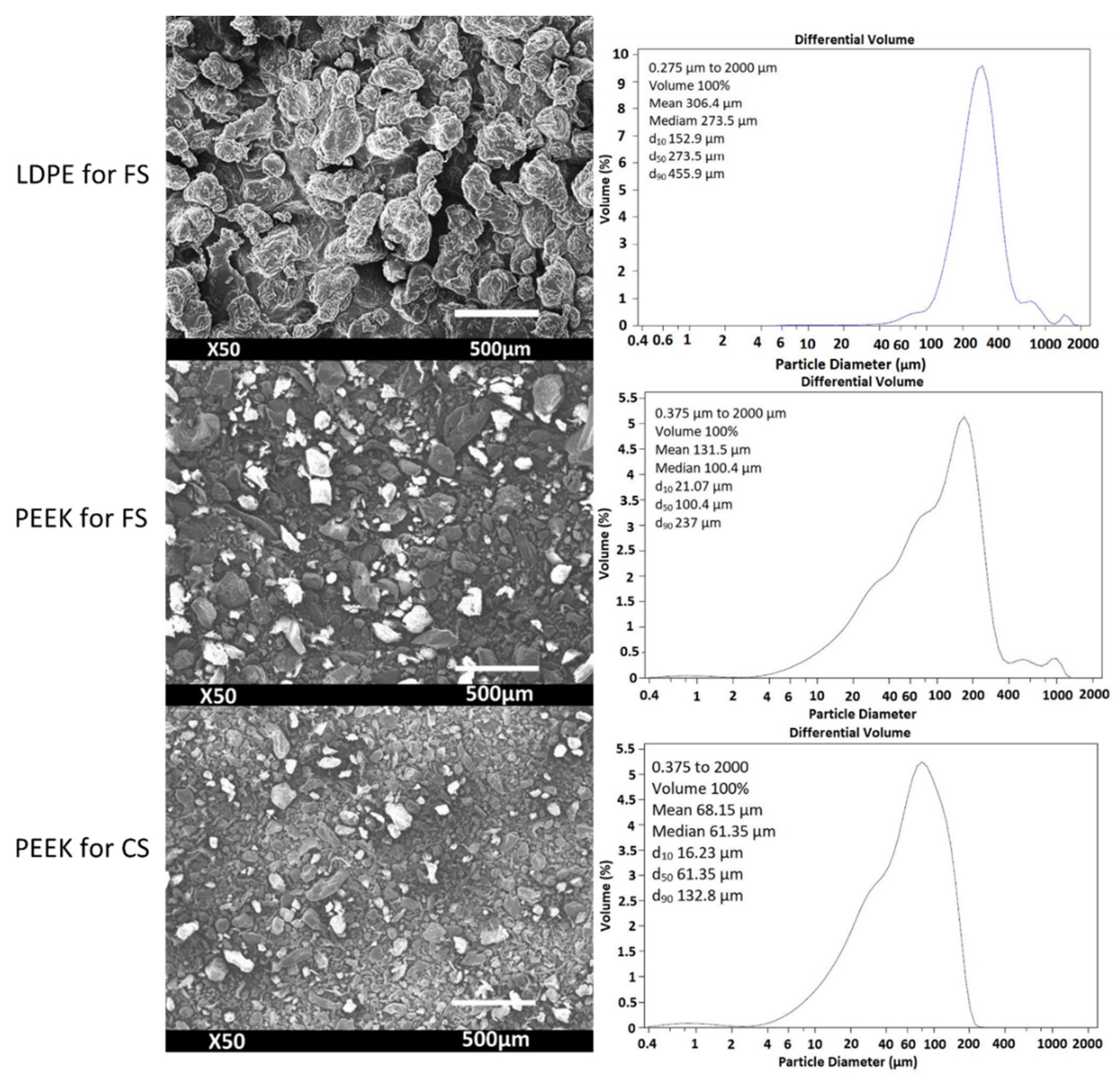
Figure 4.
Optical microscope images of the cross-sections of FS-PE, FS-PEEK, and CS-PEEK coatings.
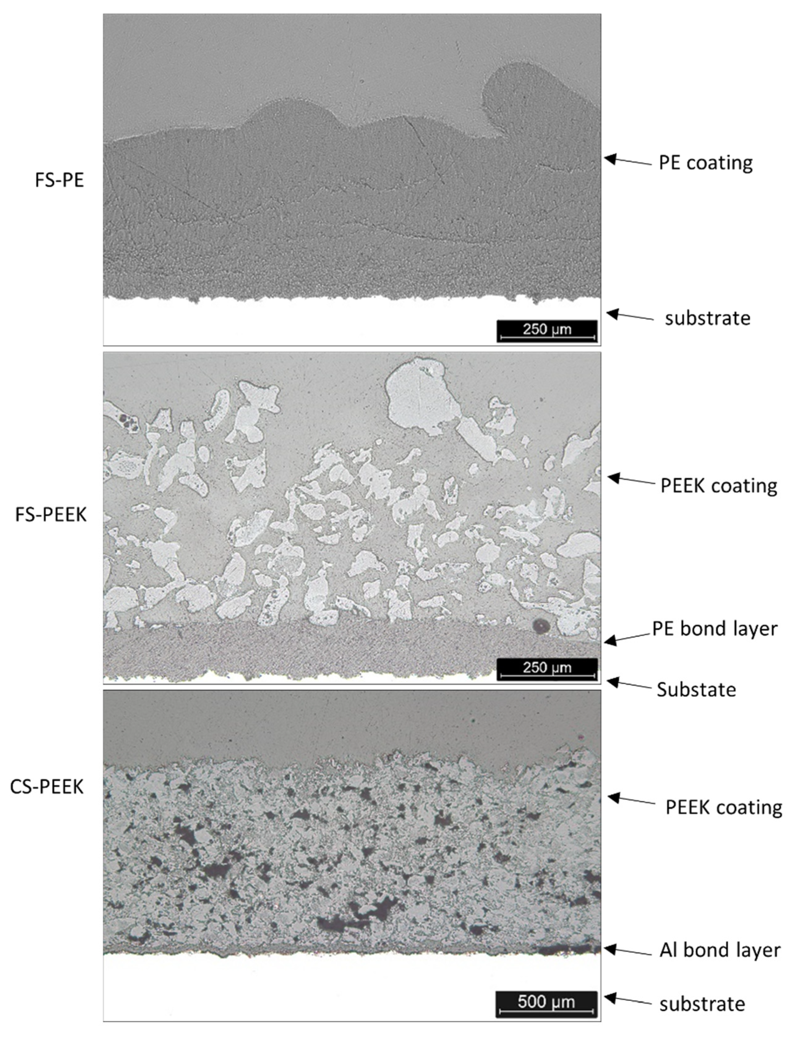
Figure 5.
SEM images of the fracture surface of FS-PE coating.
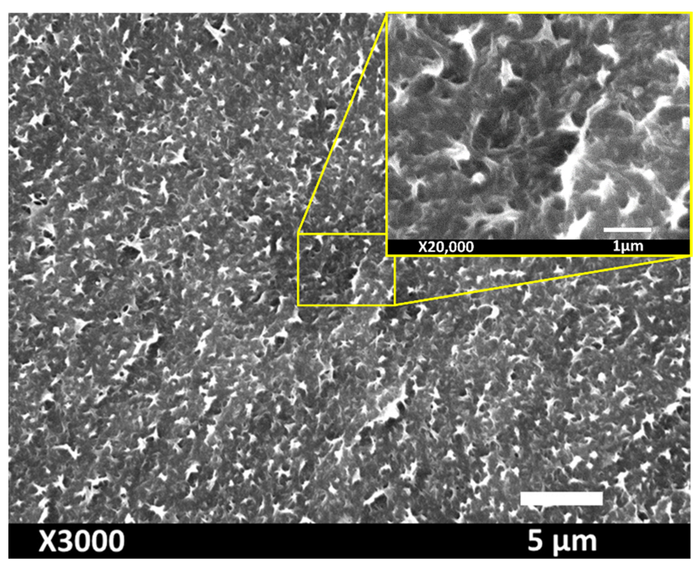
Figure 6.
SEM images of FS-PE, FS-PEEK, and CS-PEEK coating surfaces and their topographies.
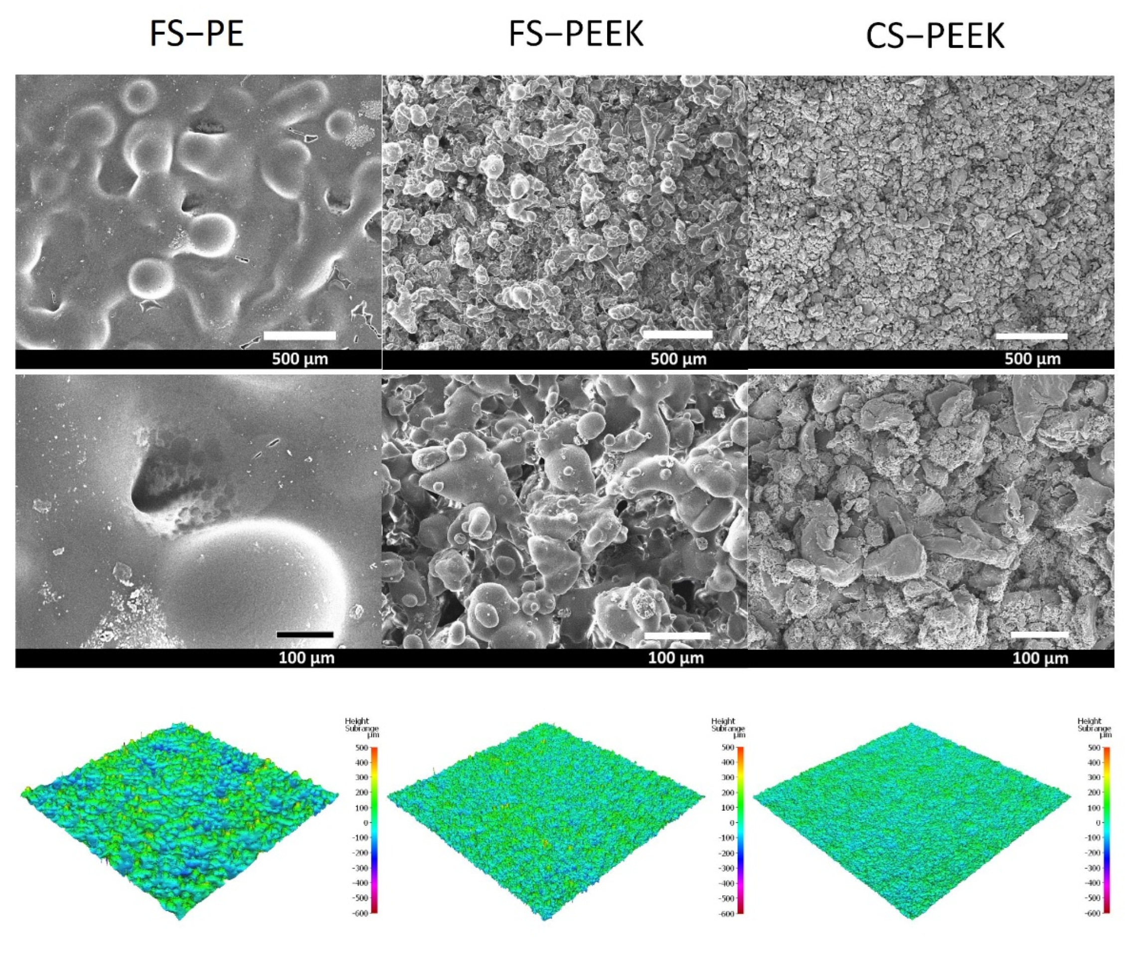
Figure 7.
Ice adhesion of FS-PE SLIPS, FS-PEEK SLIPS, and CS-PEEK SLIPS and FS-PE, FS-PEEK, and CS-PEEK coatings after first icing–deicing test.
Figure 7.
Ice adhesion of FS-PE SLIPS, FS-PEEK SLIPS, and CS-PEEK SLIPS and FS-PE, FS-PEEK, and CS-PEEK coatings after first icing–deicing test.
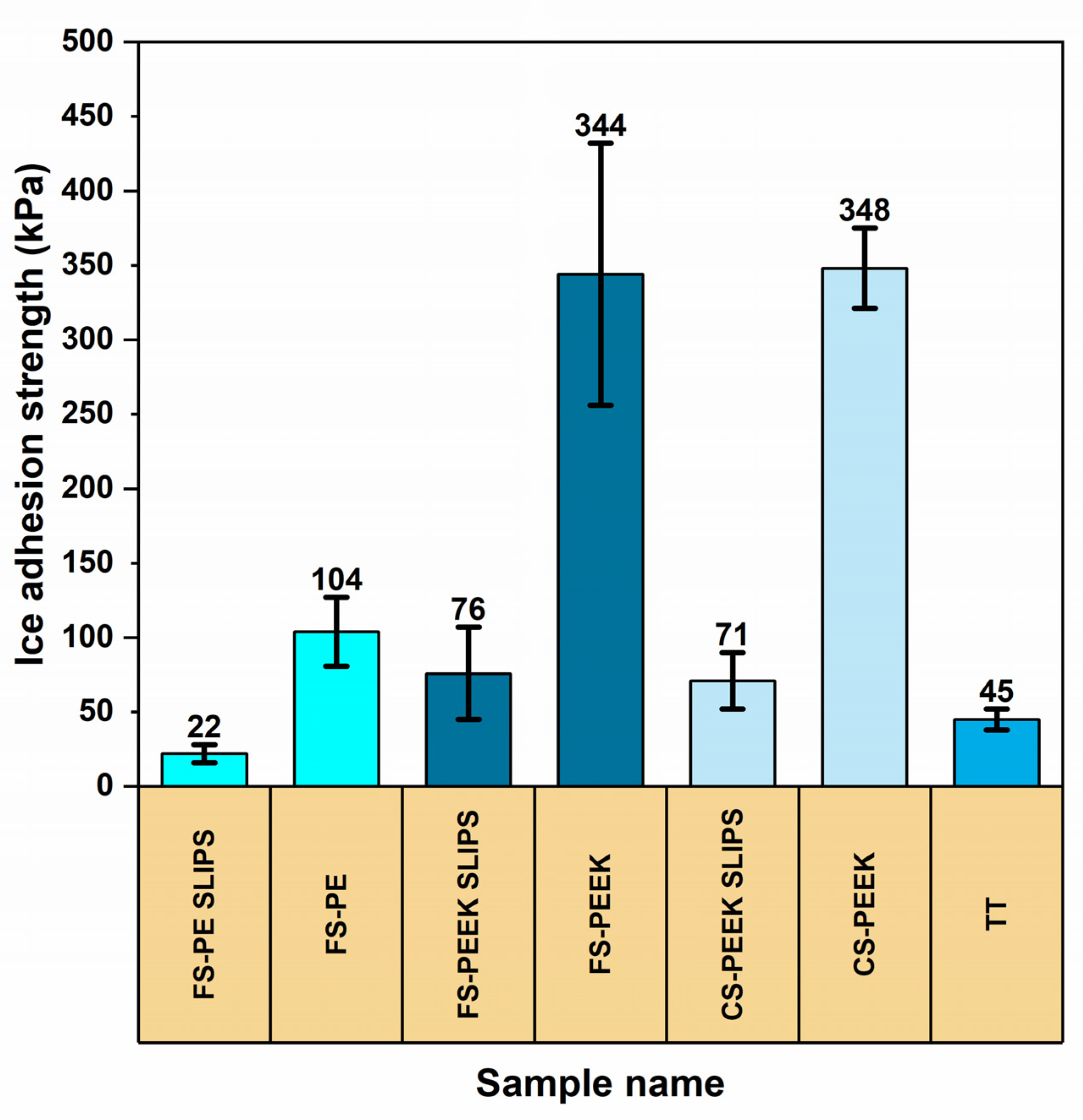
Figure 8.
Cyclic icing–deicing test results for FS-PE, FS-PEEK, and CS-PEEK coatings and with four icing–deicing cycles for SLIPS.
Figure 8.
Cyclic icing–deicing test results for FS-PE, FS-PEEK, and CS-PEEK coatings and with four icing–deicing cycles for SLIPS.
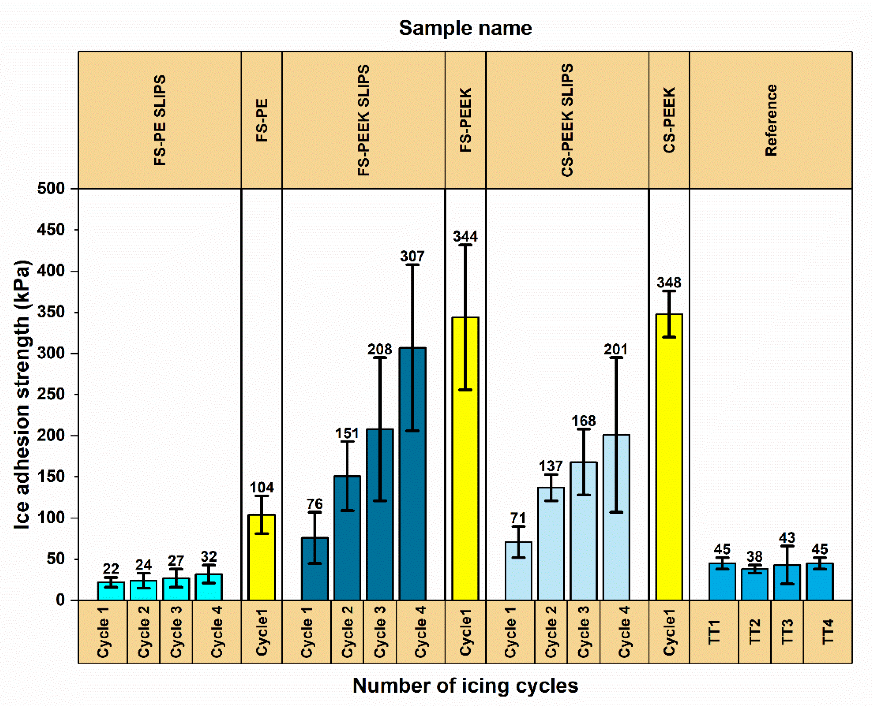
Figure 9.
FTIR spectra for the silicon oil, porous coatings, and SLIPS before and after cyclic icing–deicing test.
Figure 9.
FTIR spectra for the silicon oil, porous coatings, and SLIPS before and after cyclic icing–deicing test.
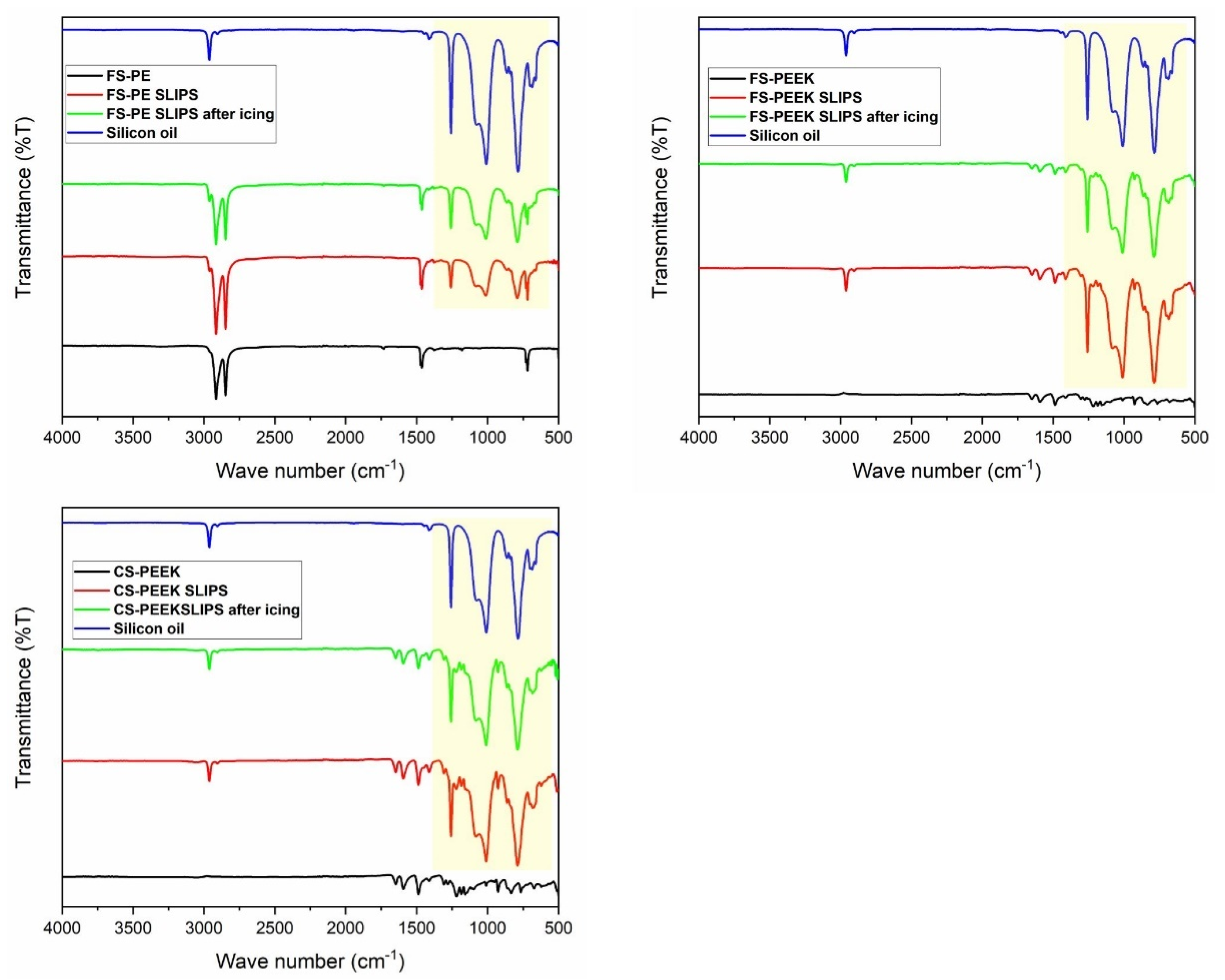
Figure 10.
Water droplets of 5 µL on FS-PE, FS-PEEK, and CS-PEEK coatings and FS-PE SLIPS, FS-PEEK SLIPS, and CS-PEEK SLIPS, before and after cyclic icing—deicing tests for measuring the apparent WCA.
Figure 10.
Water droplets of 5 µL on FS-PE, FS-PEEK, and CS-PEEK coatings and FS-PE SLIPS, FS-PEEK SLIPS, and CS-PEEK SLIPS, before and after cyclic icing—deicing tests for measuring the apparent WCA.

Figure 11.
Wetting behavior of FS-PE, FS-PEEK, and CS-PEEK coatings and FS-PE SLIPS, FS-PEEK SLIPS, and CS-PEEK SLIPS before and after cyclic icing–deicing tests; * refers to pinned samples and ** refers to failed samples during ice adhesion test.
Figure 11.
Wetting behavior of FS-PE, FS-PEEK, and CS-PEEK coatings and FS-PE SLIPS, FS-PEEK SLIPS, and CS-PEEK SLIPS before and after cyclic icing–deicing tests; * refers to pinned samples and ** refers to failed samples during ice adhesion test.
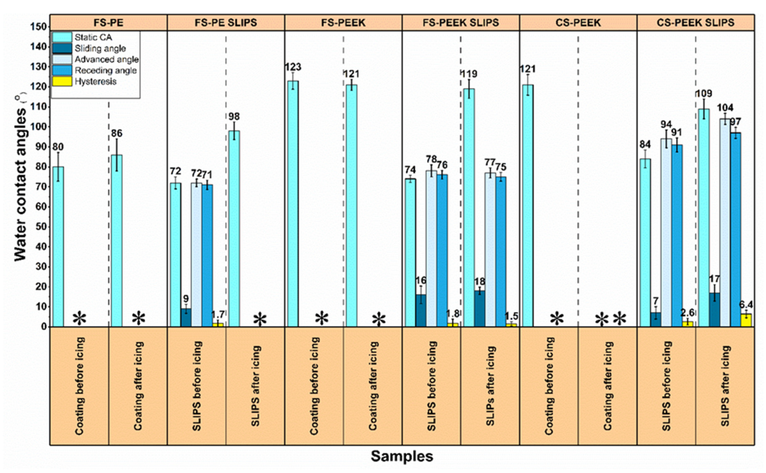
Figure 12.
SEM images of the FS-PE and FS-PEEK porous coating surfaces after icing test and their corresponding surface topographies. Areas marked with yellow squares represent the cohesive failure in FS-PEEK coating after the cyclic icing–deicing test.
Figure 12.
SEM images of the FS-PE and FS-PEEK porous coating surfaces after icing test and their corresponding surface topographies. Areas marked with yellow squares represent the cohesive failure in FS-PEEK coating after the cyclic icing–deicing test.

Table 1.
Feedstock powder specifications according to the supplier’s information.
| Powder | Melting Point (°C) | Bulk Density (g/cm3) | Particle Size (µm) |
|---|---|---|---|
| LDPE PEEK | 107 | 0.36 | 300 |
| 340 | 1.3 | 110 for FS | |
| 55 for LPCS |
Table 2.
Flame-spray parameters.
| Sample | Spray Nozzle Type | O2 Pressure (Bar) | C2H2 Pressure (Bar) | Spray Distance (mm) | Moving Speed (mm/s) | Step Size (mm) |
|---|---|---|---|---|---|---|
| FS-PE | M10 | 4.2 | 0.7 | 250 | 500 | 5 |
| FS-PEEK | M40 | 4.0 | 0.7 | 250 | 500 | 5 |
| PE bond layer | M10 | 4.2 | 0.7 | 250 | 500 | 5 |
Table 3.
Low-pressure cold-spray parameters.
| Sample | Air Heat Temperature (°C) | Air Pressure (Bar) | Spray Distance (mm) | Moving Speed (mm/s) | Step Size (mm) |
|---|---|---|---|---|---|
| CS-PEEK | 320 | 4.2 | 10 | 50 | 1 |
| Al bond layer | 540 | 6 | 10 | 50 | 1 |
Table 4.
Ice accretion parameters in IWiT at TAU’s Ice Laboratory.
| Temperature (°C) | Relative Humidity (%) | Wind Speed (m/s) | Ice Type |
|---|---|---|---|
| −10 | 83–86 | 25 | Mixed glaze |
Table 5.
Surface roughness values of FS-PE, FS-PEEK, and CS-PEEK porous coatings before and after icing test. Sa is the areal roughness. * Samples failed after CAT.
Table 5.
Surface roughness values of FS-PE, FS-PEEK, and CS-PEEK porous coatings before and after icing test. Sa is the areal roughness. * Samples failed after CAT.
| Before Icing Tests | After Icing Tests | |
|---|---|---|
| Coating | Sa (µm) | Sa (µm) |
| FS-PE | 65 | 47 |
| FS-PEEK | 53 | 55 |
| CS-PEEK | 31 | * |
Publisher’s Note: MDPI stays neutral with regard to jurisdictional claims in published maps and institutional affiliations. |
© 2022 by the authors. Licensee MDPI, Basel, Switzerland. This article is an open access article distributed under the terms and conditions of the Creative Commons Attribution (CC BY) license (https://creativecommons.org/licenses/by/4.0/).
Share and Cite
MDPI and ACS Style
Khammas, R.; Koivuluoto, H. Durable Icephobic Slippery Liquid-Infused Porous Surfaces (SLIPS) Using Flame- and Cold-Spraying. Sustainability 2022, 14, 8422. https://doi.org/10.3390/su14148422
AMA Style
Khammas R, Koivuluoto H. Durable Icephobic Slippery Liquid-Infused Porous Surfaces (SLIPS) Using Flame- and Cold-Spraying. Sustainability. 2022; 14(14):8422. https://doi.org/10.3390/su14148422
Chicago/Turabian StyleKhammas, Ruqaya, and Heli Koivuluoto. 2022. "Durable Icephobic Slippery Liquid-Infused Porous Surfaces (SLIPS) Using Flame- and Cold-Spraying" Sustainability 14, no. 14: 8422. https://doi.org/10.3390/su14148422
Note that from the first issue of 2016, this journal uses article numbers instead of page numbers. See further details here.