
Research on the Key Technology of Gob-Side Entry Retaining by Roof Cutting for Thick and Hard Sandstone Roofs


1
Huaneng Coal Technology Research Co., Ltd., Beijing 100070, China
2
Transportation Institute, Inner Mongolia University, Hohhot 010070, China
3
School of Mine and Coal, Inner Mongolia University of Science and Technology, Baotou 014010, China
*
Authors to whom correspondence should be addressed.
Sustainability 2022, 14(16), 9941; https://doi.org/10.3390/su14169941
Submission received: 9 July 2022
/
Revised: 1 August 2022
/
Accepted: 8 August 2022
/
Published: 11 August 2022
(This article belongs to the Special Issue Sustainable Development and Utilization of Coal Measures Resources)
Abstract
:In order to ensure the application of gob-side entry retaining by roof cutting for thick and hard sandstone roofs, the key technology of pre-split blasting was studied. The LS-DYNA was used to analyze the blasting effect of the energy-gathering pipe. Using the methods of theoretical analysis and numerical simulation, it was determined that the optimal cutting height was 16 m and the optimal cutting angle was 15°. The effect of pressure relief by roof cutting was verified by FLAC3D. It is proposed to use deep-hole loosening blasting to solve the problem of the sandstone with a thick hard roof being difficult to collapse. A group of loose blasting holes was designed to be arranged every 20 m in the gob-side roadway. The depth of the #1 blasthole was 47 m, and the angle to the horizontal direction was 20°; the depth of the #2 blasthole was 65 m, and the angle to the horizontal direction was 15°. A field test was carried out in the 7135 ventilation roadway of Qidong Coal Mine China. The on-site peeping results showed that the blasting with the energy-gathering pipe had a good effect of directional slitting. After deep-hole loosening blasting, the thick hard sandstone roof collapsed and filled the gob in time. The monitoring curves of the hydraulic support showed that the hydraulic support resistance of the working face in the side with roof cutting was much smaller than that of the side without roof cutting, and the effect of pressure relief by roof cutting was good.
1. Introduction
Unlike the traditional gob-side entry retention, the gob-side entry retaining by roof cutting cuts off the roof strata of the roadway and the gob using bidirectional concentrated blasting technology [1,2,3]. After the working face is mined, the roof strata of the gob collapse and form a new rib. Because the technology abandons the traditional idea of “replacing the coal pillar with the backfill”, it effectively solves the problem that the backfill is prone to dynamic pressure disasters due to stress concentration [4,5,6].
Since it was proposed by academician Manchao He in 2006, the technology of gob-side entry retaining by roof cutting has been successfully applied in various geological conditions in China [7,8,9], such as thin coal seams, medium-thick coal seams, thick coal seam, large buried depths, large dip angles and other geological conditions; the gob-side entry retaining by roof cutting has a good entry retaining effect with significant economic benefits [10,11]. However, the research on thick and hard roofs is relatively scarce. The thick and hard roof is difficult to collapse. The key of gob-side entry retaining by roof cutting is the timely collapse of the thick hard roof.
2. Key Technology of Gob-Side Entry Retaining by Roof Cutting
2.1. Process Flow of Gob-Side Entry Retaining by Roof Cutting
The process flow of gob-side entry retaining by roof cutting is shown in Figure 1, (1) In order to ensure the stability of the roadway during the reuse period, high prestressed anchors are used to support the roof before the working face is mined [12,13]. (2) Bidirectional energy-gathering blasting technology is used to pre-split the roof strata of the roadway, cut off the connection of the roof strata between the roadway and the gob, and ensure that the roof strata collapse in time after the working face is mined to fill the gob and form a new rib of the roadway [2,14]. (3) After the working face is mined, in order to ensure the stability of the roof strata, the roadway is temporarily supported by single pillar [15,16]. (4) When the gob-side roadway is stabilized, the single pillar can be removed, and only the gangue retaining is retained [17].
2.2. Key Technology of Gob-Side Entry Retaining by Roof Cutting
In the above analysis, it can be seen that compared with the traditional gob-side entry retaining, the process of gob-side entry retaining by roof cutting is simple, and the reinforcement support, the temporary support of single pillar, and the gangue retaining are easy to operate [18,19]. The most difficult process link of gob-side entry retaining by roof cutting is the bidirectional energy blasting. The bidirectional energy-gathering blasting technology is realized by the energy-gathering pipe. The symmetrical openings on both sides of the energy-gathering pipe form the blasting weak surface. After the explosive is detonated, the detonation wave will form a directional energy-gathering flow in the direction of the weak surfaces on both sides of the energy-gathering pipe, and will form a squeezing effect on the roof strata [20,21]. As shown in Figure 2, the detonation wave generates concentrated tensile stress along the strike direction of the working face, forcing the pre-split blasting hole to penetrate in the direction of energy accumulation, and fracturing the roof strata directionally.
In order to study the effect of the bidirectional energy-gathering blasting of the energy-gathering pipe, taking the #7 coal seam of Qidong Coal Mine China as the engineering background, the LS-DYNA was used for analysis. Taking the section of energy-gathering blasting as the calculation object, a plane stress model was established, and a single-layer grid was used for calculation. According to the engineering situation, the blasting model was established at the ratio of 1:1. The blasting model is shown in Figure 3, the model is composed of the rock unit, air unit, explosive unit, and energy-gathering pipe unit. The inner diameter of the energy-gathering pipe is 3.6 cm, the outer diameter is 4.2 cm, and the slit width is 0.4 cm; the diameter of the explosive is 3.2 cm. The computational model was simplified to a plane stress state with a thickness of 0.5 cm. The explosive was detonated at the center point, and the air boundary condition was set to a non-reflection boundary. In order to reveal its energy-gathering effect, a blasting model with the same size and the same parameters except the energy-gathering pipe was established for comparative analysis.
The model adopted solid164 elements and used the division method of mapped mesh. The meshes of each element are shown in Figure 4. The numerical modeling parameters are shown in Table 1, Table 2 and Table 3.
The stress evolution process of non-energy-gathering blasting is shown in Figure 5, and the development process of non-energy-gathering blasting cracks is shown in Figure 6. After the explosive was detonated, a strong detonation stress wave was formed. When the blasting stress wave reached the wall of the blasting hole, compressive shear stress was formed. With the superposition of blasting stress waves, the concentration of compressive stress in the surrounding rock near the blast hole wall was getting higher and higher. When the compressive stress exceeded the compressive strength of the surrounding rock, a large number of cracks were generated in the surrounding rock near the hole wall, and a compressive shear failure zone was formed around the blasting hole. After the compression-shear failure zone was formed, the explosive stress wave formed the tensile stress concentration zone along six directions in the surrounding rock. Under the action of tensile stress, the surrounding rock cracked uniformly in six directions along 60° to form six tensile cracks, and the tensile stress concentration appeared at the crack tip. With the continuous propagation of the burst stress wave, the crack tip was continuously broken and opened under the action of tensile stress, resulting in the continuous expansion of the crack in six directions until it penetrated. In the case of non-energy-gathering blasting, the surrounding rock was broken as a whole under the action of the detonation stress wave, and the blasting effect was poor.
The stress evolution process of energy-gathering blasting is shown in Figure 7, and the development process of energy-gathering blasting cracks is shown in Figure 8. Immediately after the explosive was detonated, a tensile stress concentration zone appeared near the blasting hole, and the nearby rocks were subjected to the action of tensile stress. When the tensile stress exceeded the tensile strength of the surrounding rock, tensile cracks were generated in the surrounding rock near the blasting hole. After the initial tension crack was formed, the surrounding rock cracked along the horizontal single energy-gathering direction under the action of tension stress to form a tension crack. With the continuous propagation of the burst stress wave, the crack tip was continuously broken and opened under the action of tensile stress, resulting in the continuous expansion of the crack in the direction of energy accumulation until it penetrated. In the case of energy-gathering blasting, the cracks developed and expanded along the direction of the energy-gathering, the surrounding rock was not broken as a whole under the action of the detonation stress wave, and the effect of shaped energy blasting was good.
3. Research on Presplit Blasting Technology
According to the above analysis, the process flow of gob-side entry retaining by roof cutting was simple, and the construction of the highly prestressed anchor cable reinforcement support, single temporary support and gangue retaining support were all simple. The most difficult technical aspect was pre-splitting and roof cutting [22,23]. Especially with the condition of a thick and hard roof, whether the roof can collapse in time to fill the gob after roof cutting was directly related to the success of roadway retention. The parameters of roof cutting included the height and angle of roof cutting [24,25].
3.1. The Height of the Roof Cutting
The reasonable height of roof cutting should ensure that the caving gangue filled the gob under the action of fragmentation and expansion. It can effectively support the overlying rock layer, place the overlying rock layer in a stable state as soon as possible, and reduce the influence of dynamic pressure on the surrounding rock of the roadway. The reasonable height of the roof cutting can be calculated by the following formula [26]:
where HQ is the height of roof cutting in m; H is the thickness of the coal seam in 3.3 m; H1 is the roof subsidence in m; H2 is the bottom drum in m; and K is the bulking coefficient in 1.3.
Without considering the roof subsidence and bottom drum, it can be calculated that HQ = 11 m.
Because the thickness of the fine sandstone above the #7 coal seam is 17 m and the integrity is good, in order to ensure the effect of pressure relief by roof cutting, the while fine sandstone should be cut off. Therefore, considering the above theoretical calculation, the reasonable height of roof cutting is 17 m.
3.2. The Angle of the Roof Cutting
The pre-splitting and blasting the roof strata of the roadway before the working face is mined, and the angle of roof cutting is too small, which is not conducive to the stability of the roof of the roadway, and will bring difficulties to the roadway support; the angle is too large, which is not conducive to the collapse of the roof in the gob. The reasonable angle of roof cutting should be conducive to the roof collapse of the gob, and should ensure the stability of the roadway. The schematic diagram of the roof after pre-split blasting can be simplified as shown in Figure 9.
In order to determine a reasonable angle of the roof cutting, FLAC3D was used to analyze the angles of 5°, 10°, 15°, and 20°, respectively. The vertical stress distribution of the surrounding rock of the roadway with the different angles of the roof cutting is shown in Figure 10.
When the angles were 5°, 10°, 15°, and 20°, after the working face was mined, the stress concentration area on the rib of roadway was 10 m, 10.5 m, 11 m, and 10 m away from the roadway, respectively. The results showed that under the influence of pre-split blasting, the stress peak shifts to the depth of the coal formation. The maximum values of vertical stress were 30.4 MPa, 27.5 MPa, 27.1 MPa and 33.6 MPa, respectively. Considering the stress concentration position and stress distribution of the surrounding rock of the roadway, the effect of pressure relief by roof cutting was better when the angle of roof cutting was 10° or 15°, the effect was worse when the angle was 5°, and the effect was worst when the angle was 20°. Considering the construction conditions on site, the reasonable angle of roof cutting was 15°.
3.3. The Effect of Pressure Relief by Roof Cutting
FLAC3D numerical simulation software was used to study the effect of pressure relief by roof cutting with the above-mentioned parameters of roof cutting. During the mining of the working face, the vertical stress distribution of the surrounding rock of the roadway is shown in Figure 11.
As shown in Figure 11, when the working face was advanced by 40 m, the vertical stress value of the working face with roof cutting was 9.22 MPa, and the vertical stress value of the working face without roof cutting was 14.13 MPa. When the working face was advanced by 80 m, the vertical stress value of the working face with roof cutting was 8.43 MPa, and the vertical stress value of the working face without roof cutting was 13.22 MPa. When the working face was advanced by 120 m, the vertical stress value of the working face with roof cutting was 7.89 MPa, and the vertical stress value of the working face without roof cutting was 13.15 MPa. When the working face was advanced by 160 m, the vertical stress value of the working face with roof cutting was 9.13 MPa, and the vertical stress value of the working face without roof cutting was 14.25 MPa. The numerical simulation results showed that in the working face, the vertical stress in the middle of the working face was the largest. The vertical stress of working face with roof cutting was reduced by 37.6% on average compared with the working face without roof cutting.
4. Special Technical Measures for Thick and Hard Sandstone Roofs
Thick and hard sandstone roofs are not easy to collapse, and special technical measures should be taken to ensure that the roof strata can collapse in time after the working face is mined [27,28,29]. According to the site conditions of Qidong Coal Mine, it was determined that the technology of deep-hole blasting should be used to promote the timely collapse of the thick and hard roof.
- (1)
- The Diameter of the Blasting Hole
Considering the site construction conditions and previous blasting effects, it was determined that the diameter of the blasting hole for the deep-hole blasting should be the same as that of the bidirectional blasting hole, which was 50 mm.
- (2)
- The Spacing of the Blasting Hole
The reasonable spacing of the blasting hole should ensure that the cracks in the thick hard roof rock layer were fully developed, and should ensure that the roof rock layer could collapse in time after the working face is mined, and a large area of overhanging roof is not formed [30]. When the blasting hole was parallel to the working face, according to the theory of fracture mechanics, the distance between the loose blasting holes could be calculated by the following formula [31]:
where E is the spacing of the blasting hole in m; K is the regulation factor, 15; rb is the radius of the blasting hole, 25 mm; and f is the Protodyakonov coefficient, 9.
According to our calculations, the spacing of the blasting hole is 0.78 m. Considering the convenience of construction comprehensively, the spacing of blasting hole was determined to be 1 m.
- (3)
- The Depth of the Blasting Hole
The depth of the unidirectional blasting hole can be calculated by the following formula [32]:
where S1 is the depth of the blasting hole in m; S is the length of the working face, 180 m; d is the horizontal distance from the bottom of the hole to the roadway in m; α is the angle between the blasthole and the roadway, 90°; and β is the angle between the blast hole and the working face in °. Taking into account the site conditions and construction conditions, the depths of the blasting holes were designed to be 65 m and 47 m.
- (4)
- The Blast Cycle Interval
The initial falling distance [33] of the roof strata can be calculated by the following formula:
where Lc is the initial falling distance of the roof stratum in m; m is the thickness of the roof stratum, 17 m; σt is the tensile strength of the roof stratum, 4 MPa; and γ is the volumetric weight of the roof stratum, 2.5 × 10⁴ N/m3.
According to our calculations, the initial caving interval of the roof stratum is 73.76 m. According to the mining experience of #7 coal seam in Qidong Coal Mine, the periodic caving interval of the roof stratum is 1/3 of the initial caving interval. Therefore, the periodic caving interval of the roof stratum is 24.59 m. According to the principle that the blasting cycle interval should not exceed the periodic caving interval of the roof stratum and the construction quantity, the blasting cycle interval was determined to be 20 m. By the above analysis, the arrangement of the blasting hole is shown in Figure 12. A group of blasting holes was arranged every 20 m in the roadway with roof cutting, and each group of blasting holes consists of two blasting holes. The depth of the #1 blasting hole was 47 m, and the angle with the horizontal direction was 20°; the depth of the #2 blasting hole was 65 m, and the angle with the horizontal direction was 15°. The two blasting holes were arranged perpendicular to the advancing direction of the working face, and the diameters of the blasting holes were both 50 mm.
5. Engineering Application
Based on the design scheme, the field test was carried out in the 7135 ventilation roadway. The technology of gob-side entry retaining by roof cutting was used to keep the 7135 ventilation roadway as the 7133 haulage gateway, so as to alleviate the tension of mine replacement and improve the coal recovery rate.
The mining depth of the 7135 working face is 520 m, the average thickness is 3.3 m, the dip angle is 13°, and the strike length and the dip length are 1688 m and 180 m, respectively.
According to the design scheme, the height of the roof cutting is 17 m, the length of the energy-gathering pipe is 1.5 m, seven energy-gathering pipes are set in each blasting hole, and the length of the sealing mud is 6.5 m. Because the roof stratum is not only thick, but also hard, in order to ensure the effect of roof cutting, it is determined that we should use the method of combined hole blasting for pre-split blasting. The quantification of explosives of a single hole was carried out on site. As shown in Table 4 a total of five sets of test scheme were designed on site.
After the on-site blasting, the effect of the bidirectional energy-gathering blasting was tested with a drilling peep instrument. The results showed that after the blasting with Scheme 1, the effect of fracturing was poor, such that Scheme 2 added two explosives on the basis of Scheme 1. After the blasting with Scheme 2, the effect of fracturing was better than Scheme 1, but it was still not ideal. Therefore, Scheme 3 continued to add three explosives on the basis of Scheme 2. After the blasting with Scheme 3, the effect of fracturing was better than that of Scheme 2, but there was hole collapse in some areas. Therefore, Scheme 4 reduced one explosive on the basis of Scheme 3. After the blasting with Scheme 4, the crack could penetrate the blasting hole without hole collapse. The effect of fracturing was better than Scheme 3. Consider from the economic cost, Scheme 5 reduced one explosive on the basis of Scheme 4. After the blasting with Scheme 5, the effect of the fracturing was worse than that of Scheme 4. To sum up, Scheme 4 was the best scheme. The effect of the fracturing of Scheme 4 is shown in Figure 13a, and the quantity of explosive of Scheme 4 is shown in Figure 13b.
Arranging the blasting hole according to the design plan made the roof strata collapse and filled the gob in time after the working face was mined. The effect of the roof caving after the working face was mined is shown in Figure 14a, and the effect of gob-side entry retaining by roof cutting is shown in Figure 14b.
In order to research the effect of pressure relief by roof cutting, the working resistance of the hydraulic support was monitored in real time. The change of the working resistance of the #3 hydraulic support in the side without roof cutting and the #118 hydraulic support in the side with roof cutting are shown in Figure 15. The maximum values of the working resistance of the #3 and #118 hydraulic supports were 28.2 MPa and 19.5 MPa, respectively. The working resistance of the hydraulic support in the side with roof cutting was much smaller than that of the side without roof cutting.
6. Conclusions
Taking the #7 coal seam of Qidong Coal Mine as the engineering background, the following conclusions were obtained for the application of the technology of gob-side entry retaining by roof cutting with the conditions of thick and hard roof strata:
- LS-DYNA numerical simulation software was used to analyze the blasting effect under two working conditions with and without the energy-gathering pipe. The results showed that the surrounding rock cracks in a single horizontal direction under the action of the detonation wave when using the energy-gathering pipe, which could achieve the purpose of directional roof cutting.
- By theoretical analysis and numerical simulation, it was determined that the optimal height of roof cutting was 16 m, and the optimal angle of roof cutting was 15°. FLAC3D numerical simulation software was used to analyze the stress distribution of the working face. The results showed that the vertical stress near the roof cutting side was much less than that of the other side without roof cutting. The effect of pressure relief by roof cutting was good.
- It was proposed to use deep hole loosening blasting to make the thick and hard sandstone roof collapse in time to fill the gob. A group of blasting holes was arranged every 20 m in the roadway with roof cutting, and each group of blasting holes consisted of two blasting holes. The depth of the #1 blasting hole was 47 m, and the angle with the horizontal direction was 20°; the depth of the #2 blasting hole was 65 m, and the angle with the horizontal direction was 15°. The two blasting holes were arranged perpendicular to the advancing direction of the working face, and the diameters of the blasting holes were both 50 mm.
- The field test of the 7135 ventilation roadway showed that the blasting with the energy-gathering pipe had a good effect of directional slitting; after deep hole loosening blasting, the thick and hard sandstone roof could collapse and fill the gob in time; the hydraulic support resistance of the working face in the side with roof cutting was much smaller than that of the side without roof cutting, and the effect of pressure relief by roof cutting was good.
Author Contributions
Conceptualization, C.H.; methodology, Q.L.; software, E.W.; validation, Y.W.; formal analysis, Y.L.; investigation, X.S.; resources, Q.L.; data curation, C.H.; writing—original draft preparation, E.W.; writing—review and editing, C.H.; visualization, Q.L.; supervision, C.H.; project administration, Y.W.; funding acquisition, C.H. All authors have read and agreed to the published version of the manuscript.
Funding
This research was financially supported by the National Natural Science Foundation of China (No. 52074295), the Higher Educational Scientific Research Projects of Inner Mongolia Autonomous Region (No. NJZY21291), and the Science and Technology Project of China Huaneng Group Co. Ltd. (HNKJ22-HF126).
Institutional Review Board Statement
Not applicable.
Informed Consent Statement
Not applicable.
Data Availability Statement
All data included in this study are available upon request by contacting the corresponding author.
Acknowledgments
We are grateful to the anonymous reviewers for their constructive reviews on the manuscript, and to the editors for carefully revising the manuscript.
Conflicts of Interest
The authors declare no conflict of interest.
References
- Zhang, K.; Liu, C.Y.; Zhang, H.R.; Yue, X.; Liu, H.D. Research on Roof Cutting Pressure Relief of the Gob-Side Entry Retaining With Roadside Backfilling. Front. Earth Sc-Switz 2022, 10, 835497. [Google Scholar] [CrossRef]
- Lou, Q.N.; Li, T.C.; Zhu, Q.W.; Wu, S.Y.; Yun, M.; Zhao, R.L. A Control Approach of the Roof in No-Pillar Roadway Formed by Roof Cutting and Pressure Releasing. Geofluids 2021, 2021, 1–14. [Google Scholar] [CrossRef]
- Wang, Y.J.; Yang, J.; He, M.C.; Tian, X.C.; Liu, J.N.; Xue, H.J.; Huang, R.F. Test of a liquid directional roof-cutting technology for pressure-relief entry retaining mining. J. Geophys. Eng. 2019, 16, 620–638. [Google Scholar] [CrossRef]
- Liu, X.; Hua, X.Z.; Yang, P.; Huang, Z.G. A study of the mechanical structure of the direct roof during the whole process of non-pillar gob-side entry retaining by roof cutting. Ener. Explor. Exploit. 2020, 38, 1706–1724. [Google Scholar] [CrossRef]
- Yang, X.J.; Hu, C.W.; He, M.C.; Wang, H.H.; Zhou, Y.B.; Liu, X.Y.; Zhen, E.Z.; Ma, X.G. Study on Presplitting Blasting the Roof Strata of Adjacent Roadway to Control Roadway Deformation. Shock Vib. 2019, 2019, 1–16 https://doi101155/2019/3174898. [Google Scholar] [CrossRef]
- Tu, M.; Zhao, G.M.; Zhang, X.Y.; Bu, Q.W.; Dang, J.X. Fracture Evolution between Blasting Roof Cutting Holes in a Mining Stress Environment. Minerals 2022, 12, 418. [Google Scholar] [CrossRef]
- He, M.C.; Wang, Q.; Wu, Q.Y. Innovation and future of mining rock mechanics. J. Rock Mech. Geotech. 2021, 13, 1–21 https://doi101016/jjrmge202011005. [Google Scholar] [CrossRef]
- Wang, E.Y.; Chen, X.D.; Yang, X.J. Research and Application of an Innovative 110 Mining Method in Gob-Side Half Coal Rock Entry Retaining. Shock Vib. 2021, 2021, 8228604. [Google Scholar] [CrossRef]
- Wang, Y.J.; Wang, Q.; Tian, X.C.; Wang, H.S.; Yang, J.; He, M.C. Stress and deformation evolution characteristics of gob-side entry retained by roof cutting and pressure relief. Tunn. Undergr. Sp. Tech. 2022, 123, 104419. [Google Scholar] [CrossRef]
- Zhang, Q.; He, M.C.; Guo, S.; Qi, J.C.; Yang, J.; Wang, C.; Xia, M.; Li, L.N. Investigation on the key techniques and application of the new-generation automatically formed roadway without coal pillars by roof cutting. Int. J. Rock Mech. Min. 2022, 152, 105058. [Google Scholar] [CrossRef]
- Li, Z.H.; Tao, Z.G.; Meng, Z.G.; He, M.C. Longwall mining method with roof-cutting unloading and numerical investigation of ground pressure and roof stability. Arab. J. Geosci. 2018, 11, 697. [Google Scholar] [CrossRef]
- Liu, X.Y.; He, M.C.; Wang, J.; Ma, Z.M. Research on Non-Pillar Coal Mining for Thick and Hard Conglomerate Roof. Energies 2021, 14, 299. [Google Scholar] [CrossRef]
- Yan, S.; Liu, T.X.; Bai, J.B.; Wu, W.D. Key Parameters of Gob-Side Entry Retaining in A Gassy and Thin Coal Seam with Hard Roof. Processes 2018, 6, 51. [Google Scholar] [CrossRef]
- Hu, C.W.; Yang, X.J.; Huang, R.F.; Ma, X.G. Presplitting Blasting the Roof Strata to Control Large Deformation in the Deep Mine Roadway. Adv. Civ. Eng. 2020, 2020, 1–15. [Google Scholar] [CrossRef]
- Tai, Y.; Yu, B.; Xia, B.W.; Li, Z.; Xia, H.C. Research on stress release for the gob-side roadway using the roof-cutting technology with a chainsaw arm. Roy. Soc. Open Sci. 2020, 7, 191663. [Google Scholar] [CrossRef] [PubMed]
- Sun, B.J.; Hua, X.Z.; Zhang, Y.; Yin, J.D.; He, K.; Zhao, C.X.; Li, Y.F. Analysis of Roof Deformation Mechanism and Control Measures with Roof Cutting and Pressure Releasing in Gob-Side Entry Retaining. Shock Vib. 2021, 2021, 1–13. [Google Scholar] [CrossRef]
- Xu, T.; Zhang, G.H.; Cheng, T.; Wang, Y.J. Simulation Research on the Surrounding Rock Stability of Gob Side Entry Retaining with Roof Cutting and Pressure Relief Based on Ecological Environment of Coal Mining. Fresen. Environ. Bull. 2021, 30, 11263–11270. [Google Scholar]
- Gao, H.N.; Gao, Y.B.; Wang, J.; Fu, Q.; Qiao, B.W.; Wei, X.J.; Zhang, X.Y. Study on Bidirectional Blasting Technology for Composite Sandstone Roof in Gob-Side Entry-Retaining Mining Method. Appl. Sci. 2021, 11, 7524. [Google Scholar] [CrossRef]
- Ge, J.J.; Xu, Y.; Huang, W.; Wang, H.B.; Yang, R.Z.; Zhang, Z.Y. Experimental Study on Crack Propagation of Rock by Blasting under Bidirectional Equal Confining Pressure Load. Sustainability 2022, 13, 2093 https://doi103390/su132112093. [Google Scholar] [CrossRef]
- Zhang, Q.; Wang, J.; Guo, S.; Gong, W.L.; Feng, L.F.; Wang, H.S.; Ming, C.; Ma, Z.M. Shaped Charge Hydraulic Blasting: An Environmental, Safe, and Economical Method of Directional Roof Cutting. Geofluids 2021, 2021, 1–20. [Google Scholar] [CrossRef]
- Yang, X.J.; Liu, C.K.; Sun, H.L.; Yue, S.L.; Ji, Y.G.; Zhang, X.Y.; Hou, L. Research on the Deformation Mechanism and Directional Blasting Roof Cutting Control Measures of a Deep Buried High-Stress Roadway. Shock Vib. 2020, 2020, 1–14. [Google Scholar] [CrossRef]
- Zhang, X.Y.; Hu, J.Z.; Xue, H.J.; Mao, W.B.; Gao, Y.B.; Yang, J.; He, M.C. Innovative approach based on roof cutting by energy-gathering blasting for protecting roadways in coal mines. Tunn. Undergr. Sp. Tech. 2020, 99, 103387. [Google Scholar] [CrossRef]
- Gao, K.; Huang, P.; Liu, Z.G.; Liu, J.; Wang, F.; Shu, C.M. Pressure Relief by Blasting Roof Cutting in Close Seam Group Mining under Thick Sandstone to Enhance Gas Extraction for Mining Safety. Processes 2021, 9, 603. [Google Scholar] [CrossRef]
- Ma, Z.Q.; Zhang, D.Y.; Cao, Y.Q.; Yang, W.; Xu, B. Study of Key Technology of Gob-Side Entry Retention in a High Gas Outburst Coal Seam in the Karst Mountain Area. Energies 2022, 15, 4161. [Google Scholar] [CrossRef]
- Yue, X.Z.; Tu, M.; Li, Y.F.; Chang, G.F.; Li, C. Stability and Cementation of the Surrounding Rock in Roof-Cutting and Pressure-Relief Entry under Mining Influence. Energies 2022, 15, 951. [Google Scholar] [CrossRef]
- Wang, Y.J.; Liu, J.N.; Yang, J.; Wang, Q.; Huang, R.F.; Tian, X.C.; He, M.C. Stability characteristics of a fractured high roof under nonpillar mining with an automatically formed roadway by using a visualized discrimination approach. Energy Sci. Eng. 2020, 8, 1541–1553. [Google Scholar] [CrossRef]
- Fu, B.J.; Tu, M.; Zhao, Q.C. Pressure Control Technology at the Hard Thick Sandstone Roof in an Island Mining Face with a Large Mining Height. Vjesn 2021, 27, 1863–1869. [Google Scholar] [CrossRef]
- Mondal, D.; Ghosh, S.; Naveen, P.; Kumar, M.; Majumder, A.; Panda, A.K. An integrated study on the geochemical, geophysical and geomechanical characteristics of the organic deposits (Coal and CBM) of eastern Sohagpur coalfield, India. Gondwana. Res. 2021, 96, 122–141. [Google Scholar] [CrossRef]
- Mondal, D.; Roy, P.N.S.; Kumar, M. Monitoring the strata behavior in the Destressed Zone of a shallow Indian longwall panel with hard sandstone cover using Mine-Microseismicity and Borehole Televiewer data. Eng. Geol. 2020, 271, 105593. [Google Scholar] [CrossRef]
- Wojtecki, L.; Mendecki, M.J.; Golda, I.; Zuberek, W.M. The Seismic Source Parameters of Tremors Provoked by Long-Hole Destress Blasting Executed During the Longwall Mining of a Coal Seam Under Variable Stress Conditions. Pure Appl. Geophys. 2020, 177, 5723–5739. [Google Scholar] [CrossRef]
- Xiang, Z.; Zhang, N.; Xie, Z.Z.; Guo, F.; Zhang, C.H. Cooperative Control Mechanism of Long Flexible Bolts and Blasting Pressure Relief in Hard Roof Roadways of Extra-Thick Coal Seams: A Case Study. Appl. Sci. 2021, 11, 4125. [Google Scholar] [CrossRef]
- Zhao, D.; Shen, Z.Y.; Li, M.H.; Liu, B.C.; Chen, Y.N.; Xie, L.N. Study on parameter optimization of deep hole cumulative blasting in low permeability coal seams. Sci. Rep. 2022, 8, 5126. [Google Scholar] [CrossRef] [PubMed]
- Bai, Y.S.; Hu, Y.Q. Overlying Strata Movement of Below Protective Seam. J. Coastal Res. 2018, 83, 193–198. [Google Scholar] [CrossRef]
Figure 1.
Process flow of gob-side entry retaining by roof cutting.

Figure 2.
Principle of energy-gathering blasting.

Figure 3.
Numerical model. (a) Model of energy-gathering blasting. (b) The charge structure of the blast hole.
Figure 3.
Numerical model. (a) Model of energy-gathering blasting. (b) The charge structure of the blast hole.

Figure 4.
Meshing of the model. (a) Air unit. (b) Rock unit. (c) Energy-gathering pipe unit. (d) Explosive unit.
Figure 4.
Meshing of the model. (a) Air unit. (b) Rock unit. (c) Energy-gathering pipe unit. (d) Explosive unit.

Figure 5.
Stress evolution process of non-energy-gathering blasting. (a) t = 0.02 ms. (b) t = 0.12 ms. (c) t = 0.22 ms.
Figure 5.
Stress evolution process of non-energy-gathering blasting. (a) t = 0.02 ms. (b) t = 0.12 ms. (c) t = 0.22 ms.
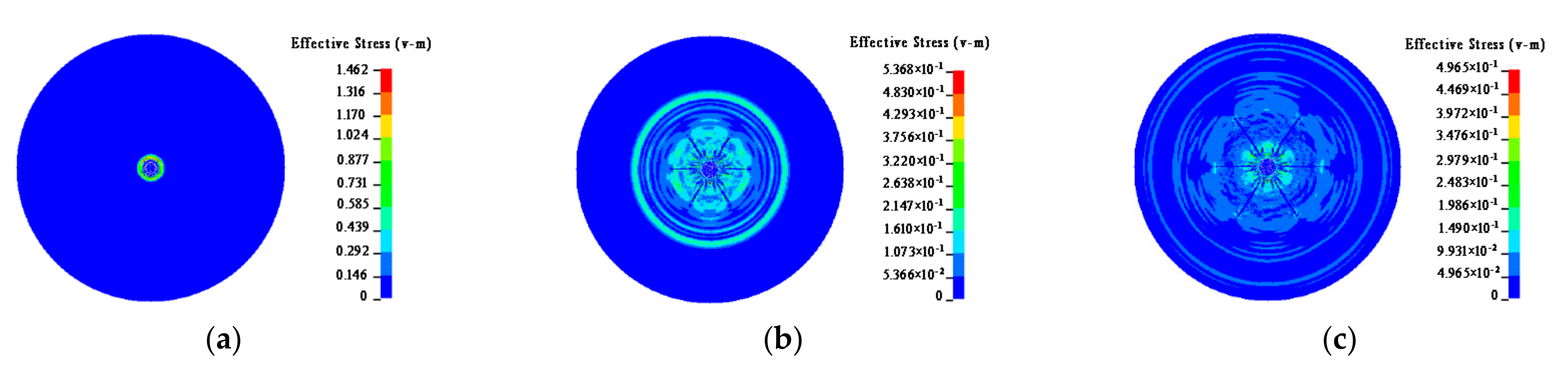
Figure 6.
Crack development process of non-energy-gathering blasting. (a) t = 0.06 ms. (b) t = 0.36 ms. (c) t = 0.66 ms.
Figure 6.
Crack development process of non-energy-gathering blasting. (a) t = 0.06 ms. (b) t = 0.36 ms. (c) t = 0.66 ms.

Figure 7.
Stress evolution process of energy-gathering blasting. (a) t = 0.02 ms. (b) t = 0.10 ms. (c) t = 0.18 ms.
Figure 7.
Stress evolution process of energy-gathering blasting. (a) t = 0.02 ms. (b) t = 0.10 ms. (c) t = 0.18 ms.
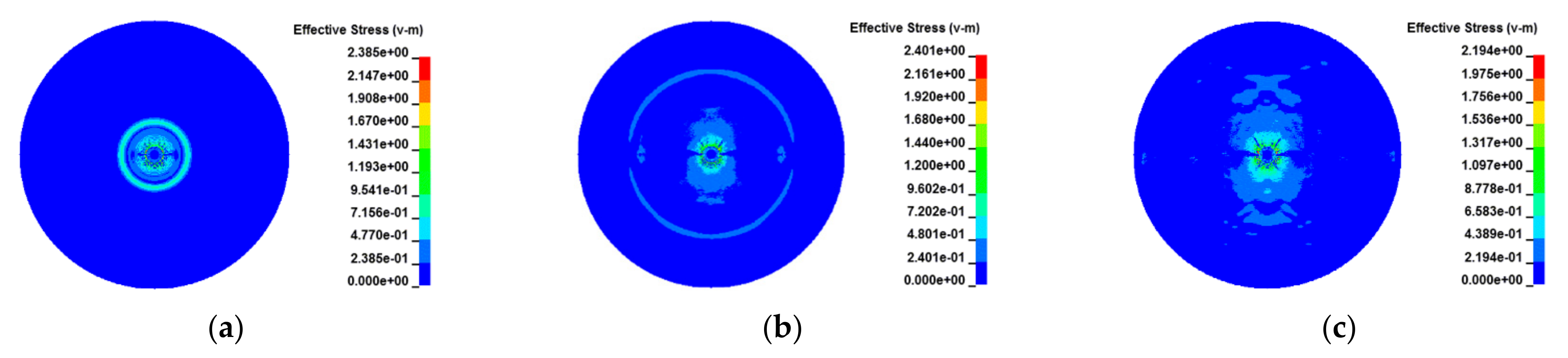
Figure 8.
Crack development process of energy-gathering blasting. (a) t = 0.02 ms. (b) t = 0.10 ms. (c) t = 0.18 ms.
Figure 8.
Crack development process of energy-gathering blasting. (a) t = 0.02 ms. (b) t = 0.10 ms. (c) t = 0.18 ms.
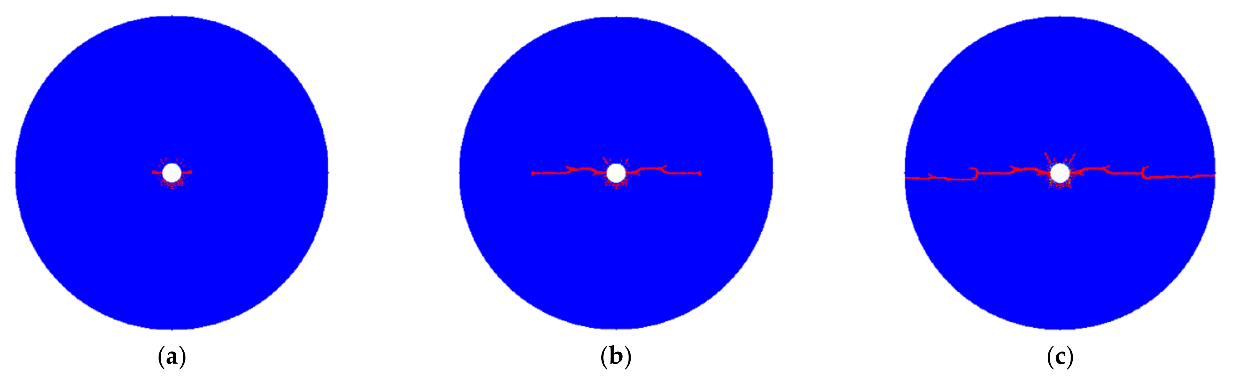
Figure 9.
Crack development process of energy-gathering blasting.

Figure 10.
Crack development process of energy-gathering blasting. (a) The angle is 5°. (b) The angle is 10°. (c) The angle is 15°. (d) The angle is 20°.
Figure 10.
Crack development process of energy-gathering blasting. (a) The angle is 5°. (b) The angle is 10°. (c) The angle is 15°. (d) The angle is 20°.
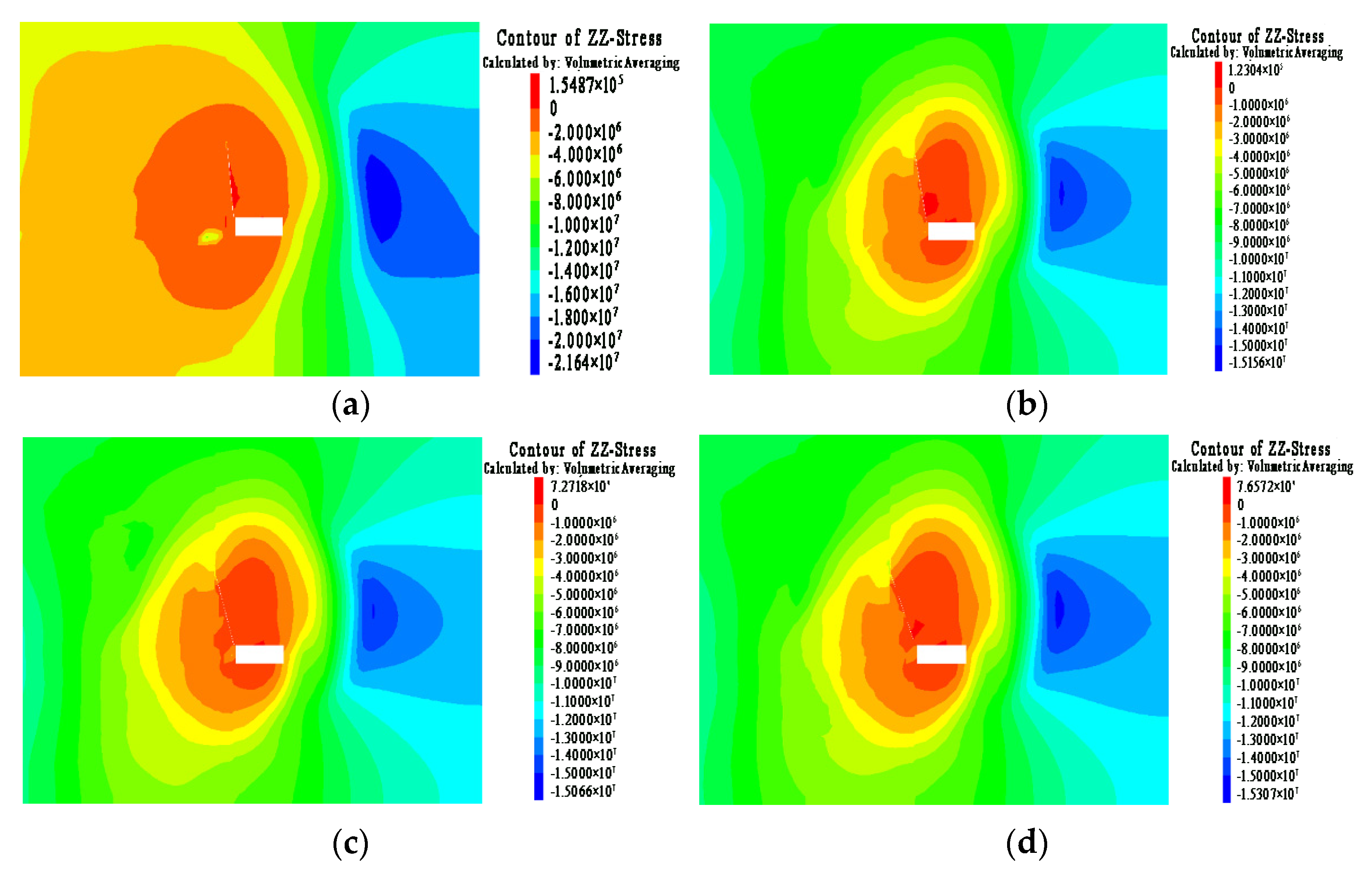
Figure 11.
Vertical stress distribution during mining. (a) The working face advanced by 40 m. (b) The working face advanced by 80 m. (c) The working face advanced by 120 m. (d) The working face advanced by 160 m.
Figure 11.
Vertical stress distribution during mining. (a) The working face advanced by 40 m. (b) The working face advanced by 80 m. (c) The working face advanced by 120 m. (d) The working face advanced by 160 m.
Figure 12.
The arrangement of the blasting holes. (a) Plan of the arrangement of the blasting holes. (b) Section of the arrangement of the blasting holes.
Figure 12.
The arrangement of the blasting holes. (a) Plan of the arrangement of the blasting holes. (b) Section of the arrangement of the blasting holes.

Figure 13.
Scheme 4. (a) The effect of the fracturing. (b) The quantity of explosive.
Figure 14.
Engineering application. (a) The effect of roof caving. (b) Gob-side entry retaining by roof cutting.
Figure 14.
Engineering application. (a) The effect of roof caving. (b) Gob-side entry retaining by roof cutting.
Figure 15.
Engineering application.


Table 1.
Mechanical parameters of the roadway’s surrounding rock.
| Lithologic | Thickness (m) | Shear (GPa) | Bulk (GPa) | Cohesion (MPa) | Friction angle (°) | Cohesion (MPa) | Density (kg/m3) |
|---|---|---|---|---|---|---|---|
| #4 coal seam | 1.7 | 2.65 | 6.48 | 2.96 | 29 | 0.73 | 1500 |
| Mudstone | 5 | 6.19 | 15.01 | 12.6 | 30 | 2.7 | 2534 |
| #5 coal seam | 0.1 | 2.65 | 6.48 | 2.96 | 29 | 0.73 | 1500 |
| Mudstone | 14.7 | 6.19 | 15.01 | 12.6 | 30 | 2.7 | 2534 |
| #6 coal seam | 0.9 | 2.65 | 6.48 | 2.96 | 29 | 0.73 | 1500 |
| Fine sandstone | 17 | 12.77 | 29.72 | 12.12 | 36 | 4.0 | 2578 |
| #7 coal seam | 3.3 | 2.65 | 6.48 | 2.96 | 29 | 0.73 | 1500 |
| Mudstone | 1.6 | 6.19 | 15.01 | 12.6 | 30 | 2.7 | 2534 |
| Medium sandstone | 28.9 | 15.58 | 20.78 | 4.12 | 37 | 7 | 2700 |
| #8 coal seam | 1.8 | 2.65 | 6.48 | 2.96 | 29 | 0.73 | 1500 |
Table 2.
Parameters of the explosive.
| Density (g/cm3) | Detonation Velocity (m/s) | Ferocity (mm) | Detonation Transmission (m) | Diameter (mm) | Power (mL) | Anti-Explosive Coupling (cm) |
|---|---|---|---|---|---|---|
| 1.1 | 2600 | ≥10 | ≥50 | 42 | ≥250 | ≥3 |
Table 3.
Parameters of the energy-gathering pipe.
| Density (g/cm3) | Bulk (GPa) | Shear (GPa) | Yield Stress (MPa) | Poisson Ratio |
|---|---|---|---|---|
| 1.43 | 43 | 3.2 | ≥50 | 42 |
Table 4.
Test scheme.
| No. | Quantity of Explosive |
|---|---|
| Scheme 1 | 3 + 3 + 3 + 2+2 + 2 + 1 |
| Scheme 2 | 3 + 3 + 3 + 3+3 + 2 + 1 |
| Scheme 3 | 4 + 3 + 3 + 3+3 + 3 + 2 |
| Scheme 4 | 4 + 3 + 3 + 3+3 + 2 + 2 |
| Scheme 5 | 4 + 3 + 3 + 3+2 + 2 + 2 |
Publisher’s Note: MDPI stays neutral with regard to jurisdictional claims in published maps and institutional affiliations. |
© 2022 by the authors. Licensee MDPI, Basel, Switzerland. This article is an open access article distributed under the terms and conditions of the Creative Commons Attribution (CC BY) license (https://creativecommons.org/licenses/by/4.0/).
Share and Cite
MDPI and ACS Style
Hu, C.; Wang, E.; Li, Q.; Wang, Y.; Li, Y.; Sha, X. Research on the Key Technology of Gob-Side Entry Retaining by Roof Cutting for Thick and Hard Sandstone Roofs. Sustainability 2022, 14, 9941. https://doi.org/10.3390/su14169941
AMA Style
Hu C, Wang E, Li Q, Wang Y, Li Y, Sha X. Research on the Key Technology of Gob-Side Entry Retaining by Roof Cutting for Thick and Hard Sandstone Roofs. Sustainability. 2022; 14(16):9941. https://doi.org/10.3390/su14169941
Chicago/Turabian StyleHu, Chaowen, Eryu Wang, Qian Li, Yilong Wang, Yongyuan Li, and Xingfeng Sha. 2022. "Research on the Key Technology of Gob-Side Entry Retaining by Roof Cutting for Thick and Hard Sandstone Roofs" Sustainability 14, no. 16: 9941. https://doi.org/10.3390/su14169941
Note that from the first issue of 2016, this journal uses article numbers instead of page numbers. See further details here.