
Effect of Mooring Parameters on Dynamic Responses of a Semi-Submersible Floating Offshore Wind Turbine
1
State Key Laboratory of Hydraulic Engineering Simulation and Safety, School of Civil Engineering, Tianjin University, Tianjin 300354, China
2
Tianjin Key Laboratory of Port and Ocean Engineering, School of Civil Engineering, Tianjin University, Tianjin 300354, China
*
Author to whom correspondence should be addressed.
Sustainability 2022, 14(21), 14012; https://doi.org/10.3390/su142114012
Submission received: 16 August 2022
/
Revised: 14 October 2022
/
Accepted: 26 October 2022
/
Published: 27 October 2022
(This article belongs to the Special Issue Ocean and Hydropower)
Abstract
:Based on a new semi-submersible floating offshore wind turbine (FOWT), a coupling aero-hydro-flexible model was established to study its dynamic behaviors, as well as the corresponding mooring system, under complicated sea scenarios. The aerodynamic load, the wave load, the current load, and the mooring load were taken into consideration. To further investigate the influence of the mooring parameters on the floating system, the diameter and the total length of mooring lines, which are the most critical parameters in mooring line design, were chosen to be analyzed. Particularly, five diameters and seven lengths were adopted to establish the FOWT mooring system, and a time-domain simulation was carried out for each cases. Based on the numerical simulations, their influences on the mooring system stiffness and the dynamic responses of FOWT were studied. The results show that the diameter has little influence on the static shape of the mooring line. The mooring system stiffness can be effectively increased by reducing the length and increasing the diameter of mooring lines. Moreover, the surge motion of floating foundation can be effectively controlled by increasing the mooring line diameter and decreasing mooring line length under the rated sea scenario. From this aspect, the dynamic response features of the FOWTs could be improved.
1. Introduction
With the traditional fossil energy crisis and environmental pollution becoming serious, renewable energy development has become one of the key approaches to overcome this predicament. Wind energy, as an easily accessible and huge-reserve renewable energy, has achieved rapid development in the past decades. Compared with onshore wind, the offshore wind speed is higher and its turbulence intensity is lower. In addition, offshore wind turbines occupy little farming resources, which releases the negative impact on the environment. Therefore, it is suitable for large-scale development and utilization. At present, with the exploitation of the offshore resources in in the China coastal shallow-water areas becoming saturated, the development of offshore wind resources has gradually moved to the far-reaching sea area, which water depths exceed 50 m.
A complete offshore wind turbine system usually consists of a turbine, a tower, a platform, and a mooring system. As the structure for energy conversion, the turbine extracts energy from the surrounding flow, which are divided into water turbines and wind turbines according to the different fluids. Based on the hydrodynamic and structural dynamics analysis, there are many research studies on water turbines and wind turbines. Zhang et al. [1,2] studied the influence of the support structure and bypass flow on the turbine wake through model experiments, expanding the knowledge of the turbine wake under waves and currents [3]. In offshore wind farms, multiple wind turbines are usually installed in one area in order to obtain power more effectively, which leads to a wake interaction. Rezvane et al. [4] proposed an innovative method to study the inflow velocity of wind turbines after considering the multiple wake effects. Giovanni et al. [5] studied the influence of turbulence on the wake dynamic mode of NREL-5MW turbine and the wind field layout is optimized according to the analysis wake model.
The present floating foundations of the FOWT are derived from the experience of offshore oil and gas platforms. The common floating platform types include semi-submersible, Spar, and TLP [6]. At present, scholars worldwide have carried out relevant research on the dynamic responses of floating wind energy facilities. For example, based on the computational fluid dynamics (CFD) method, Li et al. [7] calculated the nonlinear hydrodynamic parameters including the second-order difference-frequency wave load, the radiation wave load of the semi-submersible wind turbine platform. They found that the dynamic performance of a floating platform predicted by the modified hydrodynamic coefficient was in better agreement with the experimental results. Jiang et al. [8] proposed a stepped Spar type FOWT platform, and verified its applicability in both 50 m and 100 m water-depth conditions, according to a model test and numerical analysis. A conceptual design of reduced-draft FOWT was proposed by Zhang et al. [9], to operate in a 70 m water-depth area, and its dynamic behaviors were predicted by in their in-house numerical simulation tool. It was found that increasing the diameter of the anti-motion structure in the bottom can effectively reduce the FOWT pitch motion, as well as the mooring tension, thus improving the safety and robustness of the FOWT system. Beshbichi et al. [10] studied the dynamic response of a two-rotor wind turbine mounted on a spar floating platform by comparing it with the baseline OC3 single-rotor design. According to their results, the two-rotor design has an advantage of mass saving, but a disadvantage in motion, that is the low-frequency yaw response is increased at the rated operating wind speed. Ren et al. [11] calculated the hydrodynamic parameters and motion responses of a TLP FOWT in the case of tendon failure. The numerical prediction is based on the software WAMIT and ANSYS/AQWA. It was found that the heave, pitch, and roll motions of the FOWT were all affected with tendon failure scenarios. In addition, the natural frequency of the platform and the tension of the unbroken tendon were also affected.
As a permanent mooring structure, the FOWT maintains the energy generation in the predetermined operating area under the restriction of the mooring system to prevent the drift motion under the action of wind and waves. To some extent, the generation efficiency of the FOWT depends on the performance of the mooring system. Therefore, the mooring system of FOWT has been studied extensively. Hsu et al. [12] used commercial software to analyze the dynamic mooring load of a semi-submersible FOWT under the operating and extreme conditions. They found that the impact load might be observed in the mooring line under extreme conditions. The aerodynamic–hydrodynamic–mooring coupling dynamic analysis models were successively established by Bae et al. [13] and Li et al. [14], respectively. The dynamic response of the DeepCwind semi-submersible FOWT and the Hywind Spar FOWT were analyzed with a single mooring line broken. It was found that the mooring line failure would cause a large drift motion of the floating platform, while the mooring system is not redundancy. Yang et al. [15] demonstrated the transient dynamic response of a new multi column FOWT in the case of tendon fracture, and found that the tendon fracture connecting between the buoyancy tank and the ballast tank would have a significant influence on the pitching motion. In order to reduce the dynamic response of the semisubmersible FOWT, Giulio Ferri et al. [16], proposed a configuration optimization method of the platform and mooring system by establishing an effective frequency domain simulation model. The results show that the optimized structure has better performance and smaller platform size.
Moreover, the parametric studies have been conducted to investigate the influence of the catenary mooring line parameter on the dynamic performance of the floaters. For example, Ghafari and Dardel [17] established the numerical model of a moored semi-submersible platform model and the effects of mooring line stretch and buoy size are studied in both time and frequency domain. They found that the wider stretch and smaller buoy size could reduce the platform motions, but enlarge the tensions in the mooring lines. Wu et al. [18] numerically investigated the effect of three different mooring line types and two auxiliary mooring system on the floating current turbine which was adopted to capture the hydrokinetic energy from Kuroshio current. Their results showed that the system robustness could be achieved when the mooring mass density could exceed the corresponding thresholds. Ali et al. [19] performed sensitivity analysis on the mooring system of a deep-water turret-moored FPSO. The influences of water depth, diameter, and the hydrodynamic coefficients of the mooring line were studied. It could be observed from their results that the water depth and mooring line diameter had significant effects on surge motion reduction, but the hydrodynamic coefficients had little impact on the FPSO motion. Huang and Yang [20] optimized the mooring system of OC4 semi-submersible FOWT depending on the shallow water area with five different water depths ranging from 50 m to 100 m, based on the design rules or guidelines issued by Det Norske Veritas and American Petroleum Institute. Both the ultimate strength and fatigue damage of the catenary mooring lines were discussed via different met-ocean data. Particularly, the cost of each mooring system was carefully examined and compared. Ja’e et al. [21] further conclude the design method and the optimization techniques of the mooring system. They found that some evolutionary algorithms showed great potential and had been used for the mooring line parameter optimization works.
In the present study, a new-type semi-submersible floating platform with pontoon and three columns was adopted. For safety reasons, three groups of three mooring lines were designed, unlike the Hywind Scotland and Windfloat Atlantic. The prototype FOWT was established in the South China Sea. Moreover, previous research on the mooring system of FOWTs usually focuses on the performance of the particular mooring system under different sea conditions. In this work, more attentions are paid to the mooring line parameters’ influence on the dynamic behaviors of FOWT. We hope to provide reference for the design of other floating platforms and their corresponding mooring systems. Therefore, considering different mooring line diameters and lengths, which are the most critical parameters of the mooring line design, the effect of the mooring system on the stiffness and the dynamic response of the floating wind turbine system was analyzed based on the numerical simulation method. A coupled model with wind turbine, floating platform, and mooring system was conducted to perform the dynamic response simulations of a new semi-submersible FOWT via different mooring lines.
2. Methodology
2.1. Aerodynamic Loads
The blade element momentum theory is used to calculate the aerodynamic loads on the wind turbine. It is assumed that the blade is discretized into a plurality of independent blade elements along the length direction of the blade, and the airfoil remains unchanged along the same element. When the pressure difference is generated after the wind flow passes through the rotor, the axial and tangential induced velocities at each blade element can be calculated through the momentum loss of the wind flow, and then the thrust dT and torque dQ on the blade element can be determined by the following formula,
where ρ is the air density, W is the wind speed, B is the number of the blades, C is the chord length of the blade element profile, Cl and Cd represent the lift and drag coefficient of the blade element at the corresponding angle of attack, is the angle of incidence, and r is the distance between the blade element and the hub center. The aerodynamic load on a single blade can be obtained by integrating the distributed load along the blade span direction.
2.2. Wave Loads
In this study, the three-dimensional potential flow theory was used to calculate the hydrodynamic loads on the floating platform. This theory was developed from the linear potential flow theory, and is also one of the common tools to solve the hydrodynamic coefficient of the floating body without forward speed.
According to the linear potential flow theory, the velocity potential Φ of the floating body in the flow field is composed of three parts: the undisturbed incident velocity potential Φw, the diffraction velocity potential Φd under the assumption that the floating body is stationary, and the radiation velocity potential Φj caused by the six degree of freedom motion of the floating body. These three velocity potential terms all satisfy Laplace equation. By combining with the boundary conditions of the flow field, the velocity of the floating body can be obtained, and then the wave force on the wet surface of the floating body can be obtained by numerical integration.
At the same time, because the second-order wave load easily generates the second-order drift force of the low-frequency resonance of the mooring system, the Newman approximation method was used to deal with the second-order differential frequency wave load on the floating platform. Hereby, the wave loads could be achieved based on the following equations,
where ηi and donate the elevation and its conjugation of i-th wave component in complex domain, F1(ω) is the linear wave load transfer function, and the F2d(ωi,ωj) is difference-frequency quadric transfer function calculated by Newman approximation method.
2.3. Current Loads
The main types of ocean current include shear flow and uniform flow. The sea condition in this study is uniform flow. In uniform flow, the flow velocity at different points on the same streamline is equal, the flow velocity distribution on each cross-section is the same, and the average cross-section flow velocity is constant. The flow load acting on the surface of the floating body is estimated by the drag force formula as follows,
where, ρW is the density of sea water, CD is the drag force coefficient related to the shape, A is the force area of the floating body in the direction of positive projection of velocity, and Vcur is the relative velocity of the body.
2.4. Mooring Loads
The internal forces of mooring lines mainly affected by axial tension can be calculated by the finite element method as shown in Figure 1. The bar elements are expressed by the overall Lagrange formula. The expression is based on the Bergan method and is modified according to the comprehensive cross-section force and small strain theory. Based on the small strain theory, it can be deduced that the axial force N of the unit is:
where L0 is the initial stress-free unit length and EA is the axial stiffness. The tangential stiffness relation of the unit is derived by incremental form of virtual work principle:
In this equation, ΔSint is the increment of internal force vector, and kG and kM are the geometric stiffness matrix and the material stiffness matrix, respectively. Δv is the increment of displacement vector.
2.5. Equation of Motion in the Time Domain
For a FOWT, the platform motion governing equation in the time domain can be written as following,
where M is the body mass matrix, A is the frequency-dependent attached water quality matrix, h(t) is the retardation function, D is the nonlinear damping matrix and K is the restoring stiffness matrix of the floating body. represent the displacement, velocity, and acceleration vector of the floating body, respectively. q is the external excitation load, including the first and second order wave loads, nonlinear restoring forces provided by the mooring lines, and aerodynamic loads on the wind turbines.
The added mass and potential flow damping calculated by the three-dimensional potential flow theory are frequency-dependent, while the wave frequency components are complex under irregular wave conditions, so the added mass and potential flow damping corresponding to a certain frequency cannot be directly determined and used in the time domain equation. On this basis, the added mass and potential flow damping relating to the frequency are transformed into convolution function by convolution integration. Fourth-order Runge–Kutta numerical method was used to solve the motion response of floating platform.
3. Description of the New-Type Semi-Submersible FOWT
3.1. The Semi-Submersible Floating Platform
In previous studies on semi-submersible FOWT, the OC4 DeepCWind FOWT are usually adopted. However, in this study, we adopted a novel semi-submersible floating foundation which was composed of columns, heave plates, lower floating bodies, and square cross braces. The whole structure is arranged in an equilateral triangle for better stability. The basic structure type of the floating platform is shown in Figure 2, and the main parameters are shown in Table 1.
3.2. The Mooring System
Nine mooring lines were used in the present study, which were divided into 3 groups. Each group, which consisted of three mooring lines, was connected with the column and the lines were arranged in parallel. The configuration of mooring system is shown in Figure 3.
A single mooring line was composed of three sections. The profile is displayed in Figure 4. The upper section of the splash zone was a R3S anchor chain with a length of 20 m. The middle suspension section was R3 anchor chain with a length of 131 m; the lowest lying section was M2 anchor chain with a length of 280 m. The main parameters of each section are shown in Table 2. It should be noted that the diameter means the nominal diameter of the chains, so the thickness of the chain is same as the diameter, which is required by the international standard ISO-1074. In fact, each component and its corresponding length are designed based on the guideline approved by the China Classification Society [22]. This design meets the requirements of both buoy motion and extreme tension in the lines, like the design work based on the API or DNV guidelines in another citation [20]. These results could be observed in other publications [23,24]. It should be noted that in those works, the mooring lines are simplified as two-part cable. The Upper part S3 whose minimum broken tension is larger is merged into S2. Specifically, when analyzing the effect of mooring line diameter, since a single mooring line is composed of three sections of anchor chains of different materials, the diameter of the three sections will increase/decrease the corresponding change value on the original design parameters. When analyzing the effect of mooring line length, since the tension of the upper mooring line is greater, the length of the S3 section is defined to change, and the position of the fairlead and anchor point remains unchanged.
3.3. The Wind Turbine
NREL 5MW wind turbine [25] was adopted as the wind turbine in this study, but the tower was modified for the corresponding wind farm. To be specific, the tower column with height of 78 m, top diameter of 4.77 m, and bottom diameter of 6.96 m was redesigned according to the actual environmental conditions of offshore wind farms in China. In the numerical model, the tower column was divided into 30 sections which the diameter changes linearly, and the beam element was adopted to model the blades and tower. In other words, both bending and torsional moments on these slender structures were taken into consideration. Their dynamic behaviors were simulated by the Riflex module in the SIMA package. However, the nacelle and the rotor hub were modelled as the rigid bodies which include the six-DOF motion responses, respectively. The corresponding oscillations were predicted by the SIMO package. The models of wind turbine and tower column can be observed in Figure 5. Moreover, the semi-submersible foundation was modelled as the rigid body while the bar elements were adopted to establish the numerical model of all nine mooring lines. The geometry modelling and the hydrodynamic coefficient prediction of the floater were finished in SESAM, and the coupled model was established in SIMA.
4. Results and Discussion
In this section, two major mooring parameters are chosen to be analyzed. One is the mooring line diameter which could significantly affect the construction cost and minimum breaking loads. The other is the mooring line length. This parameter usually affects the pretension as well as the body motion. Firstly, the static restoring stiffness of the mooring system is calculated based on the finite element algorithm with different body motions. This is followed by the dynamic response simulations under the rated operation sea scenario. To perform these simulations, SIMA, one of the SESAM numerical packages is adopted. The established numerical model is shown in Figure 5. Due to the limitation of the manuscript, we hope to brief and quick display the most significant results of the FOWT, the buoy motion and the mooring tension (like the original manuscript shows), which are directly and mainly determined by the mooring system, other than spreading out all the results to make the manuscript like an engineering report. Therefore, we select two major mooring line parameters: the diameter and the length. To be specific, five sensitivity analysis cases of the mooring line diameter with a 10 mm step and seven sensitivity analysis cases of the mooring line length with a 1 m step are adopted to perform the 3 h CPU-time simulations. To avoid the stochastic influence caused by the irregular wave and the unsteady wind, we choose 10 random seeds in every case, and the statistic results displayed in the manuscript has been chosen from the same random seed.
4.1. Static Stiffness Characteristics of the Mooring System
The stiffness is one of the important design parameters of the mooring line for the large drifts in the horizontal plane of the FOWT are mainly limited by the mooring system. Among many parameters, the diameter and length of mooring line are the most important parameters to be determined in mooring design. Therefore, the finite element method described in Section 2.4 is used to analyze the mooring line mooring type and stiffness of mooring system in this section.
4.1.1. Effect of Mooring Line Diameter on Mooring Stiffness
The change of mooring line diameter will not only change the weight of mooring line, but also change the tensile stiffness of mooring line. Based on the basic principles of material mechanics and the empirical formulas obtained from classification tests, it is assumed that the weight and tensile stiffness of the mooring line are proportional to the square of the diameter. On this basis, five different diameters of mooring lines are selected for stiffness characteristics analysis. The static configuration of a single mooring line, surge sway and yaw stiffness curves of the mooring system are shown in Figure 6a–d, respectively.
It can be found from the calculation results in Figure 6a that the static shape of a single mooring line does not change when the mooring line diameter changes. However, from the stiffness curves in Figure 6b,c, it can be seen that both surge and sway stiffness of the mooring system increases with the increasing diameter, and significant nonlinearity was found when the displacement is more than 5 m which ensuring the motion of the semi-submersible FOWT in a limited range. Moreover, according to the yaw restoring moment curves, we could observe the linearity in the stiffness. Particularly, it could be seen that we the restoring stiffness of the horizontal motions is positive relative to the mooring line diameter. In order words, the larger-diameter lines could provide larger restoring force/moment for the FOWT because of the heavier weight. However, the cost of the thicker lines is undoubtedly more expensive.
4.1.2. Effect of Mooring Line Length on Mooring Stiffness
Choosing the appropriate length of mooring line is not only beneficial to guarantee positioning performance of mooring system but also to avoid excess project investment with using the too long mooring line. Therefore, the stiffness analysis of the different length is carried out with the position of the mooring pipe and anchor unchanged. On this basis, six more mooring lines in different length are selected for the stiffness analysis. The static type of the single mooring line, surge sway and yaw stiffness curves of the mooring system are shown in Figure 7a–d, respectively.
The calculation results show that the static type of the single mooring line in water changes significantly with the length changes. On the one hand, the position touching the ground of the mooring line is closer to the fairlead with the increase in length, which leads to the increase in the angle between lifting section and horizontal plane. On the other hand, the curvature of the lifting section increases with the increase in length, both of which leads to the decrease in the horizontal component of the mooring line tension. This is also confirmed by the stiffness curves of the mooring system shown in Figure 7b–d, i.e., the stiffness of the mooring system in the DOFs of surge, sway, and yaw, increases significantly as the length of the mooring line decreases. Moreover, when the mooring length is too short, the horizontal restoring stiffness is extremely large. Although this is beneficial to the positioning effect, it may cause other issues such as the large tension which will be discussed later based on the dynamic response predictions.
4.2. Dynamic Response Analysis of the Wind Turbine System
4.2.1. Free Decay Tests
Based on the three-dimensional potential flow theory described in Section 2.2, the hydrodynamic parameters of the floating platform are calculated in the frequency domain. Then we established the wind turbine-floating buoy-mooring line coupled system in the time domain, and firstly performed the free decay tests to calculate the natural frequencies of the buoy. The relaxation curves are displayed in Figure 8 and the corresponding natural periods of the platform motion are listed in Table 3. It can be observed from the results that the natural period of the floating platform in this study is large, which far away from the peaked wave period of the operational sea condition (10.0 s), so it could be derived that the buoy oscillations will be seldom affected by the resonance caused by the high-frequency wave load.
4.2.2. Environmental Conditions and Simulation Results
Based on the static stiffness analysis of the mooring system, the time domain calculation of the dynamic response characteristics of the FOWT is carried out under different mooring parameters using the integrated analysis model. The rated environmental conditions are selected considering the combined action of wind, wave, and current load in which the JONSWAP spectrum is used for wave propagation along the X-axis in the positive direction, with a significant wave height of 3.0 m and a peak period of 10.0 s. The API wind spectrum is used to simulate the turbulent wind with an average wind speed of 11.4 m/s and a constant surface current of 1.0 m/s. Each environmental load is incident along the direction of 0 degrees. Therefore, three degrees of freedom motions in the longitudinal plane are mainly analyzed, i.e., surge, pitch, and heave motions. The response of semi-submersible platform motion and mooring line tension under different conditions are obtained by 3 h simulation in the time domain. Specifically, the results of the tension are chosen from the upper chain connected with the fairlead in Line#2, because of the largest tension in the whole mooring system. An example of the time histories under the original mooring parameters is shown in Figure 9. The unstable range in the first 500 s of each time history curve is removed and the response characteristics of the motion and mooring line tension in the stable range are analyzed.
4.2.3. Effect of Mooring line Diameter on Dynamic Response
Statistical results of the platform motion under different mooring line diameters are shown in Figure 10. In the bar chart, the results of each bar are expressed as the minimum, mean, maximum, and standard deviation of the corresponding statistical variable under the relevant condition.
From the statistical results of platform motion in Figure 10a–c, it can be found that the mooring line diameter exerts a great influence on the surge and heave motion of the platform, which the surge motion decreases obviously with the increase in mooring line diameter. It can be acknowledged from the static stiffness characteristics of the mooring system that the stiffness of surge increases significantly with the increase in the mooring line diameter. Therefore, the surge motion decrease with the increase in the mooring system stiffness under the same conditions, which results in this phenomenon. At the same time, due to the increase in mooring line diameter, the mooring line mass increases, and the heave motion of the platform decreases accordingly. On the other hand, according to the statistic results of yaw motions, we could observe that the fluctuations of the yaw motion are generally decreasing with the increasing mooring line diameter. It also illustrates that the thicker and heavier mooring line could provide larger restoring stiffness which could be derived from the static results in Figure 6. The effect of mooring system on pitch motion is not significant, which shows a slightly decreasing trend with the increase in diameter. This is because the contribution of mooring system to the pitch stiffness is much smaller than that of the floating platform itself, while the coupling effect between the surge and pitch motion attributes to the slightly decreasing trend of the pitch motion. In addition, the statistical results of the tension of the mooring line shown in Figure 10e show that the tension of each mooring line increases with the increase in the diameter which due to the corresponding increase in the weight and the pre-tension of mooring line with the increase in the diameter.
4.2.4. Effect of Mooring Line Length on Dynamic Response
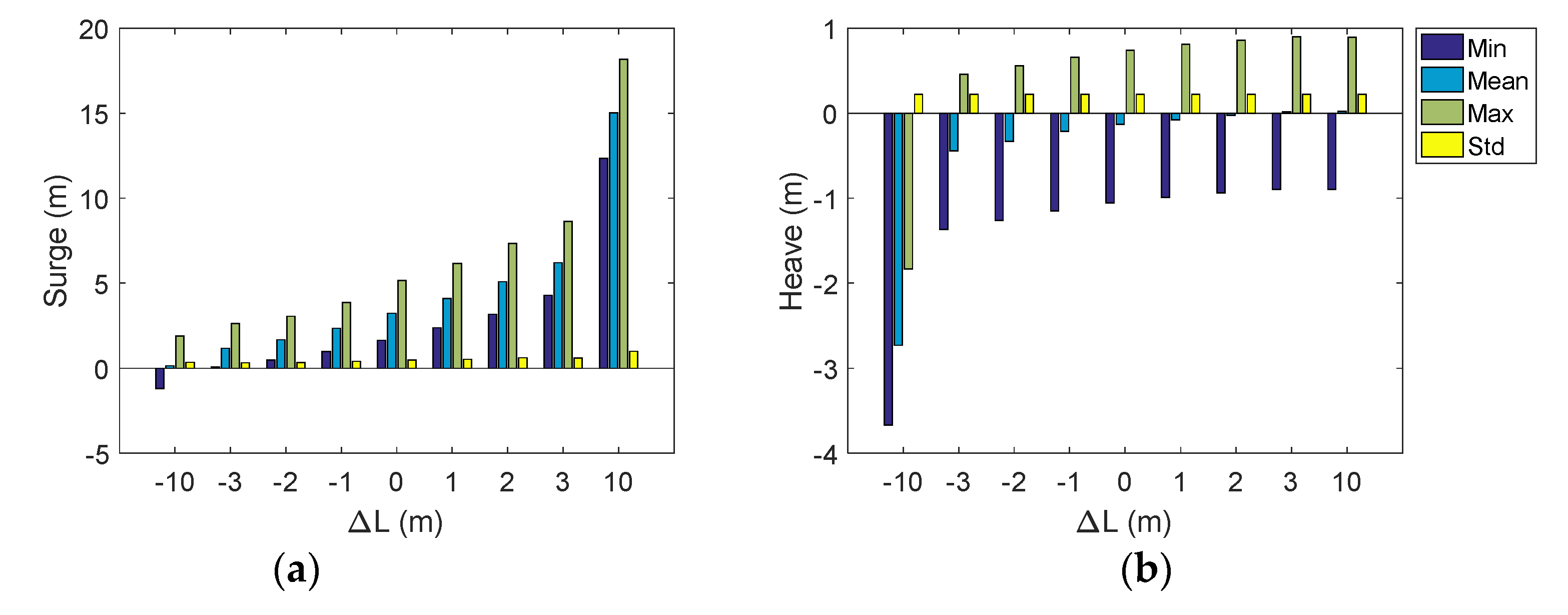
The statistic results of platform motion under different mooring line lengths are shown in Figure 11.
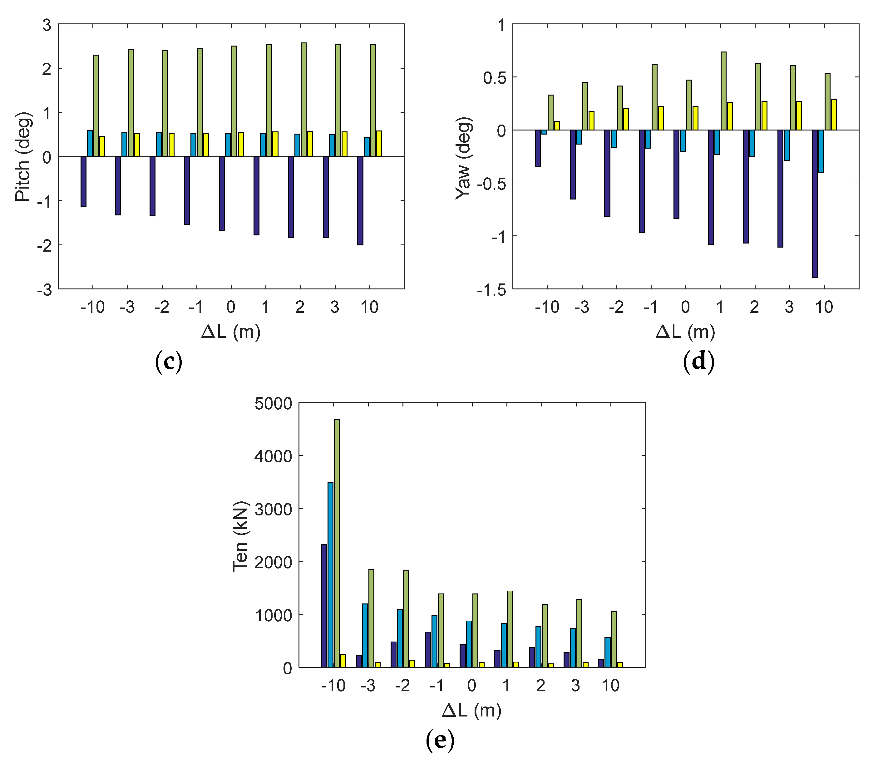
Comparing the results of Figure 10a and Figure 11a, it can be found that the effect of the length of mooring line on the surge motion is more significant than that of the diameter. With the increase in the length of mooring line, the mean and amplitude of the surge of the floating platform are enlarged, which is due to the decrease in the stiffness of mooring system caused by the increase in length. It can be found from Figure 11b that the pitch motion of the platform is less affected by the length of the mooring line. As can be seen from the statistical results of the pitch motion shown in Figure 11c, the change in the pitch amplitude is relatively small, but it shows an enlarged trend with the growth of mooring line length. This is also observed in the statistical yaw fluctuations in Figure 11d. In addition, the comparative results of Figure 10e and Figure 11e shows that the tension of each mooring line decreases as the length of the mooring line increases, which is different from the effect of changing the diameter of the mooring line. The reason is the mooring line becomes more relaxed with the increase in mooring line length, so the pre-tension as well as the dynamic tension of the mooring line tends to decrease under the environmental loads such as wind and wave. However, it should be noted that when the mooring line is too long, it will become too loose to moor the floating buoy, and the large drift may occur as the 441 m case shows. On the other hand, the shorter mooring line could significantly release the horizontal motions, but the line will become too tight. This will not only lead to the large mooring tension which may increase the fracture risk, but also will increase the set-down heave motion, as the results of the 421 m case displays. Therefore, it is necessary to choose a suitable mooring length during the design.
On the other hand, we observed an interesting phenomenon in the statistical results of mooring line loads in Figure 10e and Figure 11e. The mean value of the mooring line tension varies linearly with the diameter and length, while the change in the maximum value is slightly different from the mean value. To be specific, in some particular cases, such as the changing diameter is changing length is −3 m, −1 m, 1 m, 2 m, and 3 m, we found the minimum tension is largest in the case of −1 m, while the maximum tension was observed in the case of −2 m. In fact, due to the water depth is relative shallow (65 m), heave and pitch will also influence the extreme mooring tension. According to the results in Figure 11b, it shows that the heave motion is raised by the longer mooring line, and it means the larger vertical distance from the fairlead to the anchor and leads to the larger tension in all mooring lines. However, due to the surge motion is reduced by the longer line, the tension in line #2 will be decreased because of the smaller horizontal distance between both ends. Due to these two inconsistent factors, the mooring tension shows this interesting phenomenon. Simultaneously, the extreme tension will also be slightly influenced by the stochastic extreme wave load.
5. Conclusions
Through the research on the critical mooring design parameters such as diameter and length, the static configuration of the separate mooring line and restoring stiffness of the whole mooring system are analyzed by the finite element method. The dynamic responses of the semi-submersible FOWT are calculated based on the numerical model of wind turbine-platform-mooring system, and the following conclusions are drawn. The diameter of mooring line has little effect on the static type, but the length will significantly influence the static shape and the restoring loads in the mooring line. This is caused by the different pretension among the mooring system with different length. In addition, the stiffness of mooring system can be effectively improved by reducing the length of mooring line and increasing the diameter of mooring line. On the other hand, the surge motion of FOWT can be effectively controlled by increasing the diameter of the mooring line and decreasing the length of the mooring line under the rated operational sea scenario of the semi-submersible FOWT, while the extreme tensions in the lines will both influenced by all DOF motions of the buoy, due to the relative shallow water depth.
In present simulations, the mooring parameters are chosen based on the prototype engineering design and the changes are chosen in a small range, to show the influence and its tendency of the dynamic response of FOWT when the mooring line length and diameter change. However, it should be admitted that this is an initial step to analyze the influence in the specified range. In the following works, we will adopt the optimization algorithms (such as NAGA-III algorithm [26] and evolutionary algorithm [21]) to further investigate the global optimized mooring parameters. On the other hand, in the present work, two representative parameters, length and diameter, are adopted to performed the numerical simulations. However, there are many other parameters such as pretension, line numbers, and materials [27] In the following study, we will make additional investigations on other parameters, in order to fully grasp the key mooring parameter and its influence, so that we could provide reference for the design of other floating platforms and their corresponding mooring systems.
On the other hand, although the simulations are performed under a specific sea scenario, the results may have broader suggestion on the engineering practical. However, it should be admitted that there are many other DLCs suggested by the IEC61300 are not included in present work. We will further investigate the accidental and gust DLCs in our following investigations, so that we could fully capture the whole dynamic feature of this floating renewable energy system.
Author Contributions
Conceptualization, B.L. and J.Y.; methodology, B.L.; software, B.L.; validation, B.L. and J.Y.; formal analysis, B.L.; investigation, B.L.; resources, B.L.; data curation, B.L.; writing—original draft preparation, B.L.; writing—review and editing, B.L.; visualization, B.L.; supervision, B.L.; project administration, B.L.; funding acquisition, J.Y. All authors have read and agreed to the published version of the manuscript.
Funding
This research was funded Fund of the State Key Laboratory of Ocean Engineering, Shanghai Jiao Tong University (No. GKZD010081).
Institutional Review Board Statement
Not applicable.
Informed Consent Statement
Not applicable.
Data Availability Statement
Not applicable.
Conflicts of Interest
The authors declare no conflict of interest.
References
- Zhang, Y.; Zhang, Z.; Zheng, J.; Zhang, J.; Zheng, Y.; Zang, W.; Lin, X.; Fernandez-Rodriguez, E. Experimental investigation into effects of boundary proximity and blockage on horizontal-axis tidal turbine wake. Ocean Eng. 2021, 225, 108829. [Google Scholar] [CrossRef]
- Zhang, Y.; Zhang, J.; Lin, X.; Wang, R.; Zhang, C.; Zhao, J. Experimental investigation into downstream field of a horizontal axis tidal stream turbine supported by a mono pile. Appl. Ocean. Res. 2020, 101, 102257. [Google Scholar] [CrossRef]
- Zhang, Y.; Zang, W.; Zheng, J.; Cappietti, L.; Zhang, J.; Zheng, Y.; Fernandez-Rodriguez, E. The influence of waves propagating with the current on the wake of a tidal stream turbine. Appl. Energy 2021, 290, 116729. [Google Scholar] [CrossRef]
- Mirsane, R.S.; Farschad, T. An innovative method of investigating the wind turbine’s inflow speed in a wind farm due to the multiple wake effect issue. Energy Convers. Manag. 2022, 269, 116077. [Google Scholar] [CrossRef]
- De Cillis, G.; Cherubini, S.; Semeraro, O.; Leonardi, S.; De Palma, P. The influence of incoming turbulence on the dynamic modes of an NREL-5MW wind turbine wake. Renew. Energy 2022, 183, 601–616. [Google Scholar] [CrossRef]
- Qu, X.; Li, Y.; Tang, Y.; Hu, Z.; Zhang, P.; Yin, T. Dynamic response of spar-type floating offshore wind turbine in freak wave considering the wave-current interaction effect. Appl. Ocean Res. 2020, 100, 102178. [Google Scholar] [CrossRef]
- Li, H.; Bachynski-Polić, E.E. Validation and application of nonlinear hydrodynamics from CFD in an engineering model of a semi-submersible floating wind turbine. Mar. Struct. 2021, 79, 103054. [Google Scholar] [CrossRef]
- Jiang, Z.; Wen, B.; Chen, G.; Xiao, L.; Li, J.; Peng, Z.; Tian, X. Feasibility studies of a novel spar-type floating wind turbine for moderate water depths: Hydrodynamic perspective with model test. Ocean Eng. 2021, 233, 109070. [Google Scholar] [CrossRef]
- Zhang, J.; Li, Y.; Tang, Y.; Qu, X.; Huang, J. Analysis on dynamic response of new type reduced draft floating foundation wind turbine. Acta Energ. Sol. Sin. 2021, 42, 378–383. (In Chinese) [Google Scholar]
- El Beshbichi, O.; Xing, Y.; Ong, M.C. Dynamic analysis of two-rotor wind turbine on spar-type floating platform. Ocean Eng. 2021, 236, 109441. [Google Scholar] [CrossRef]
- Ren, Y.; Venugopal, V.; Shi, W. Dynamic analysis of a multi-column TLP floating offshore wind turbine with tendon failure scenarios. Ocean Eng. 2022, 245, 110472. [Google Scholar] [CrossRef]
- Hsu, W.; Thiagarajan, K.P.; Manuel, L. Extreme mooring tensions due to snap loads on a floating offshore wind turbine system. Mar. Struct. 2017, 55, 182–199. [Google Scholar] [CrossRef]
- Bae, Y.H.; Kim, M.H.; Kim, H.C. Performance changes of a floating offshore windturbine with broken mooring line. Renew. Energy 2017, 101, 364–375. [Google Scholar] [CrossRef]
- Li, Y.; Zhu, Q.; Liu, L. Transient response of a SPAR-type floating offshore wind turbine with fractured mooring lines. Renew. Energy 2018, 122, 576–588. [Google Scholar] [CrossRef]
- Yang, Y.; Bashir, M.; Michailides, C.; Mei, X.; Wang, J.; Li, C. Coupled analysis of a 10 MW multi-body floating offshore wind turbine subjected to tendon failures. Renew. Energy 2021, 176, 89–105. [Google Scholar] [CrossRef]
- Ferri, G.; Marino, E.; Bruschi, N.; Borri, C. Platform and mooring system optimization of a 10 MW semisubmersible offshore wind turbine. Renew. Energy 2022, 182, 1152–1170. [Google Scholar] [CrossRef]
- Ghafari, H.; Dardel, M. Parametric study of catenary mooring system on the dynamic response of the semi-submersible platform. Ocean Eng. 2018, 153, 319–332. [Google Scholar] [CrossRef]
- Wu, J.T.; Chen, J.H.; Hsin, C.Y.; Chiu, F.C. Dynamics of the FKT system with different mooring lines. Pol. Marit. Res. 2019, 26, 20–29. [Google Scholar] [CrossRef] [Green Version]
- Ali, M.O.A.; Ja’e, I.A.; Hwa, M.G.Z. Effects of water depth, mooring line diameter and hydrodynamic coefficients on the behaviour of deepwater FPSOs. Ain Shams Eng. J. 2020, 11, 727–739. [Google Scholar]
- Huang, W.H.; Yang, R.Y. Water depth variation influence on the mooring line design for FOWT within shallow water region. J. Mar. Sci. Eng. 2021, 9, 409. [Google Scholar] [CrossRef]
- Ja’e, I.A.; Ali, M.O.A.; Yenduri, A.; Nizamani, Z.; Nakayama, A. Optimisation of mooring line parameters for offshore floating structures: A review paper. Ocean Eng. 2022, 247, 110644. [Google Scholar]
- China Classification Society. Guidance Notes of the Floating Offshore Wind Turbine Platform; GD29-2021; China Classification Society: Beijing, China, 2021. (In Chinese) [Google Scholar]
- Li, H.; Zhang, K.; Dong, Y. Sensitivity analysis of dynamic response parameters of offshore floating wind turbine. Hydropower New Energy 2022, 36, 23–29. (In Chinese) [Google Scholar]
- Zhao, Z.; Fan, L.; Kuang, X.; Zhou, S.; Cheng, H. Experimental research on coupling dynamic response of semi-submersible floating offshore wind turbine. Shipbuild. China 2022, 63, 198–206. (In Chinese) [Google Scholar]
- Jonkman, J.; Butterfield, S.; Musial, W.; Scott, G. Definition of a 5-MW Reference Wind Turbine for Offshore System Development; No. NREL/TP-500-38060; National Renewable Energy Lab. (NREL): Golden, CO, USA, 2009. [Google Scholar]
- Zhang, P.; Li, Y.; Tang, Y.; Zhang, R.; Qu, X. Study on the Dynamic Behaviours of an Articulated Offshore Wind Turbine under the Severe Sea State. In Proceedings of the 9th Conference on Computational Methods in Marine Engineering (Marine 2021), Online, 2–4 June 2021. [Google Scholar]
- Xu, S. Mooring Design and Analysis for Offshore Platforms and Wave Energy Converters. Ph.D. Thesis, University of Lisbon, Lisbon, Portugal, 2021. [Google Scholar]
Figure 1.
Model of bar element.

Figure 2.
Floating platform.
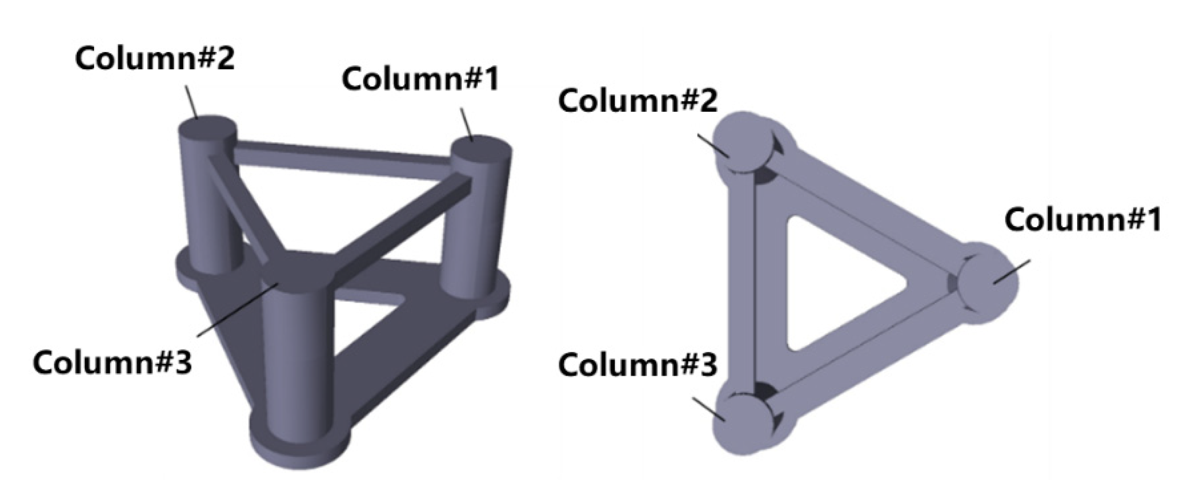
Figure 3.
Configuration of mooring system.
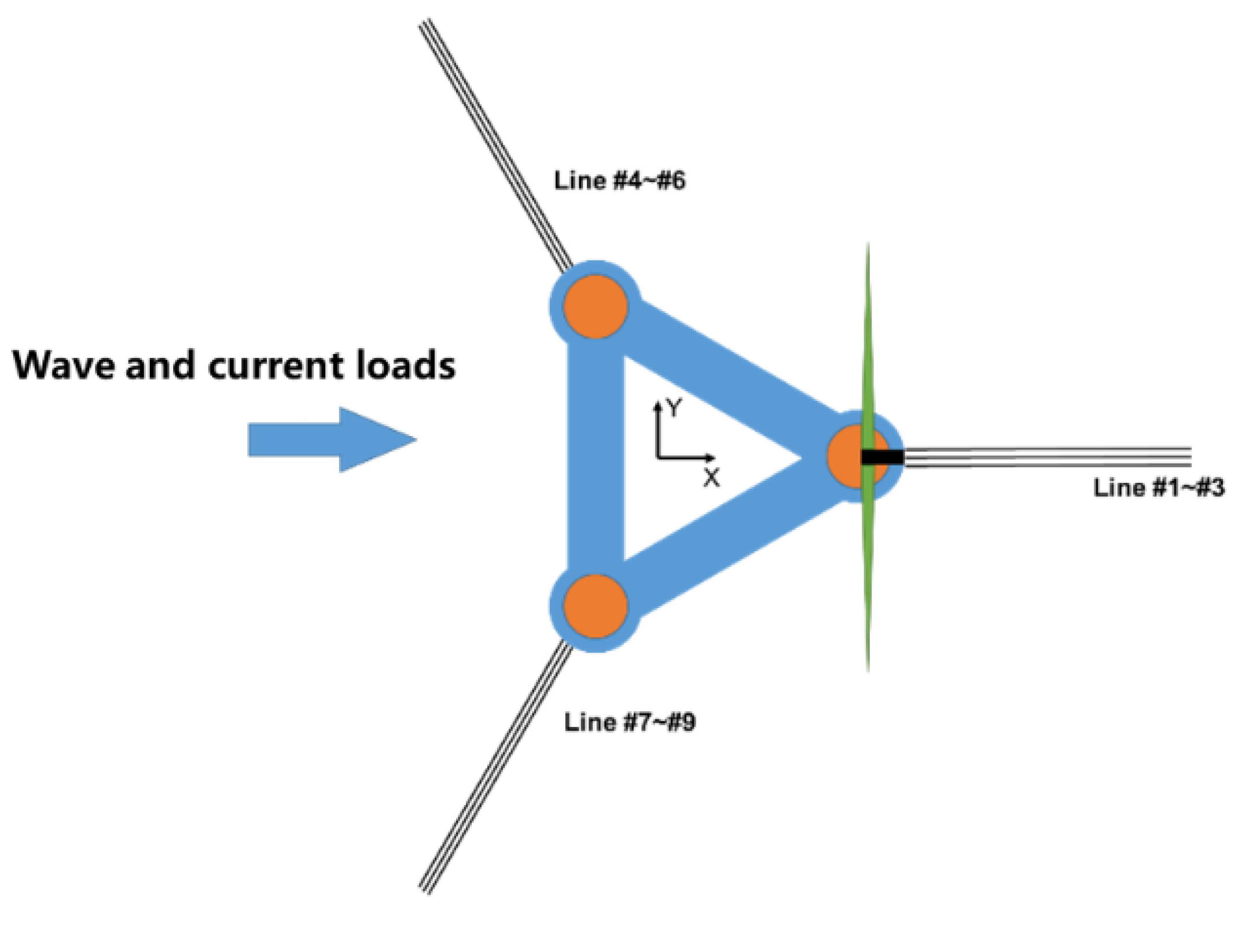
Figure 4.
Profile of the mooring line.
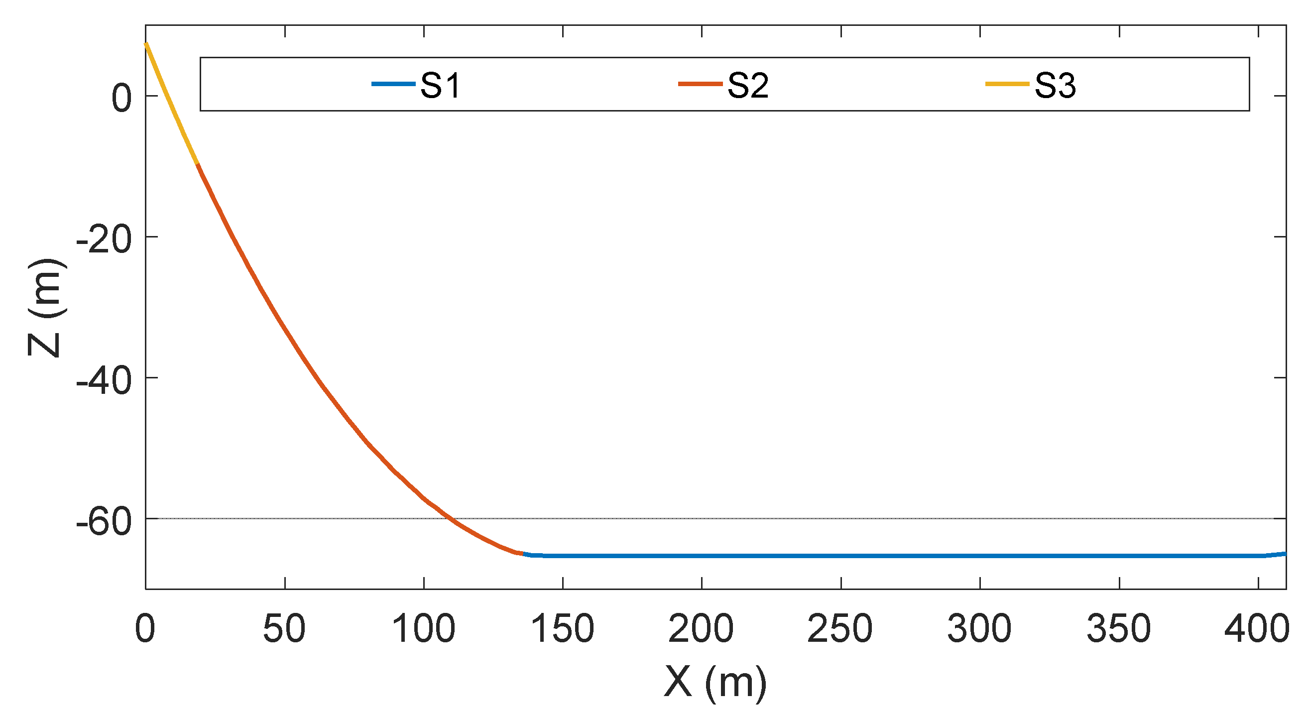
Figure 5.
Dynamic simulation model in SIMA.

Figure 6.
Effect of diameter on the static mooring stiffness. (a) Static mooring line configuration; (b) Surge Stiffness; (c) Sway Stiffness; (d) Yaw Stiffness.
Figure 6.
Effect of diameter on the static mooring stiffness. (a) Static mooring line configuration; (b) Surge Stiffness; (c) Sway Stiffness; (d) Yaw Stiffness.
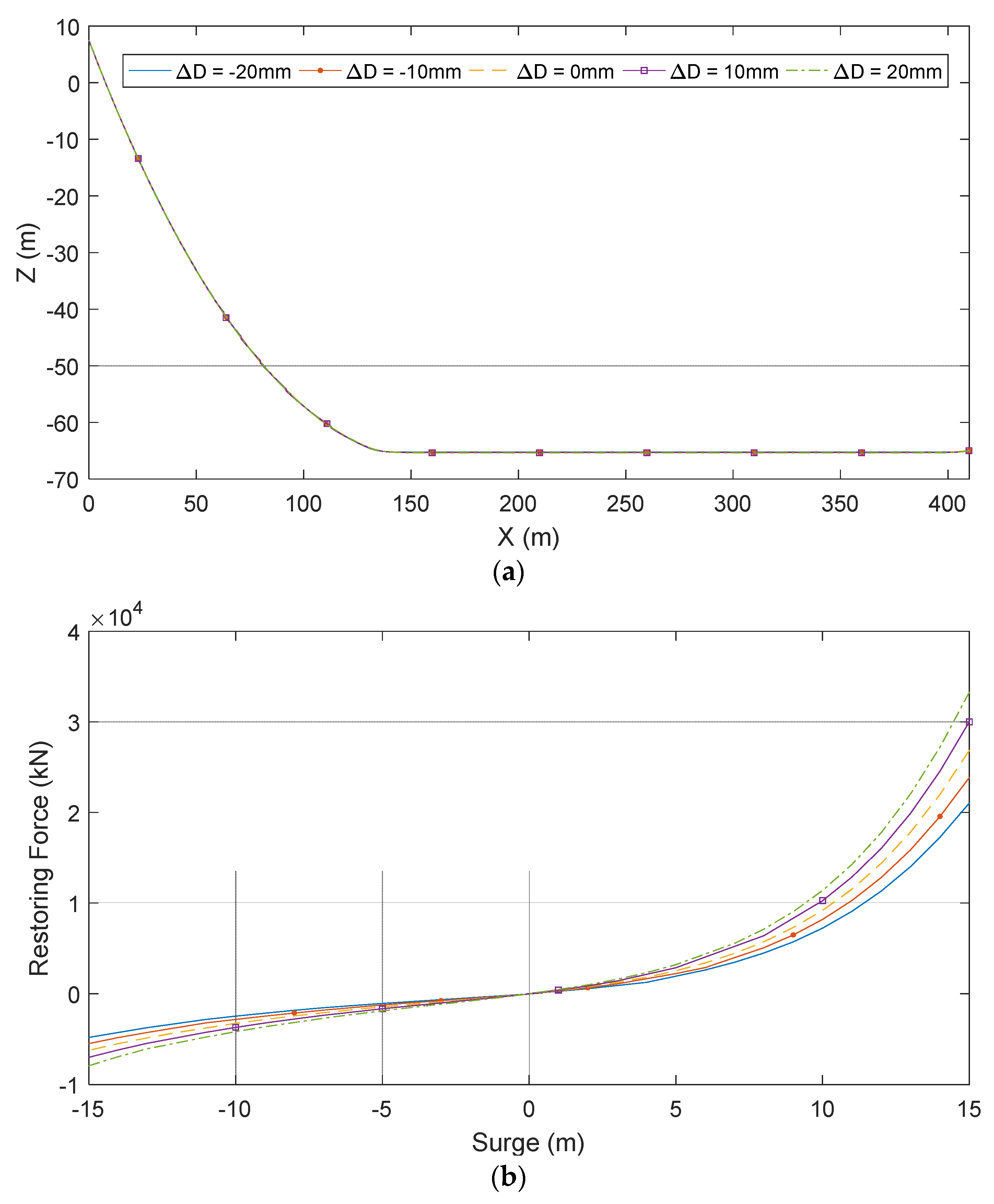
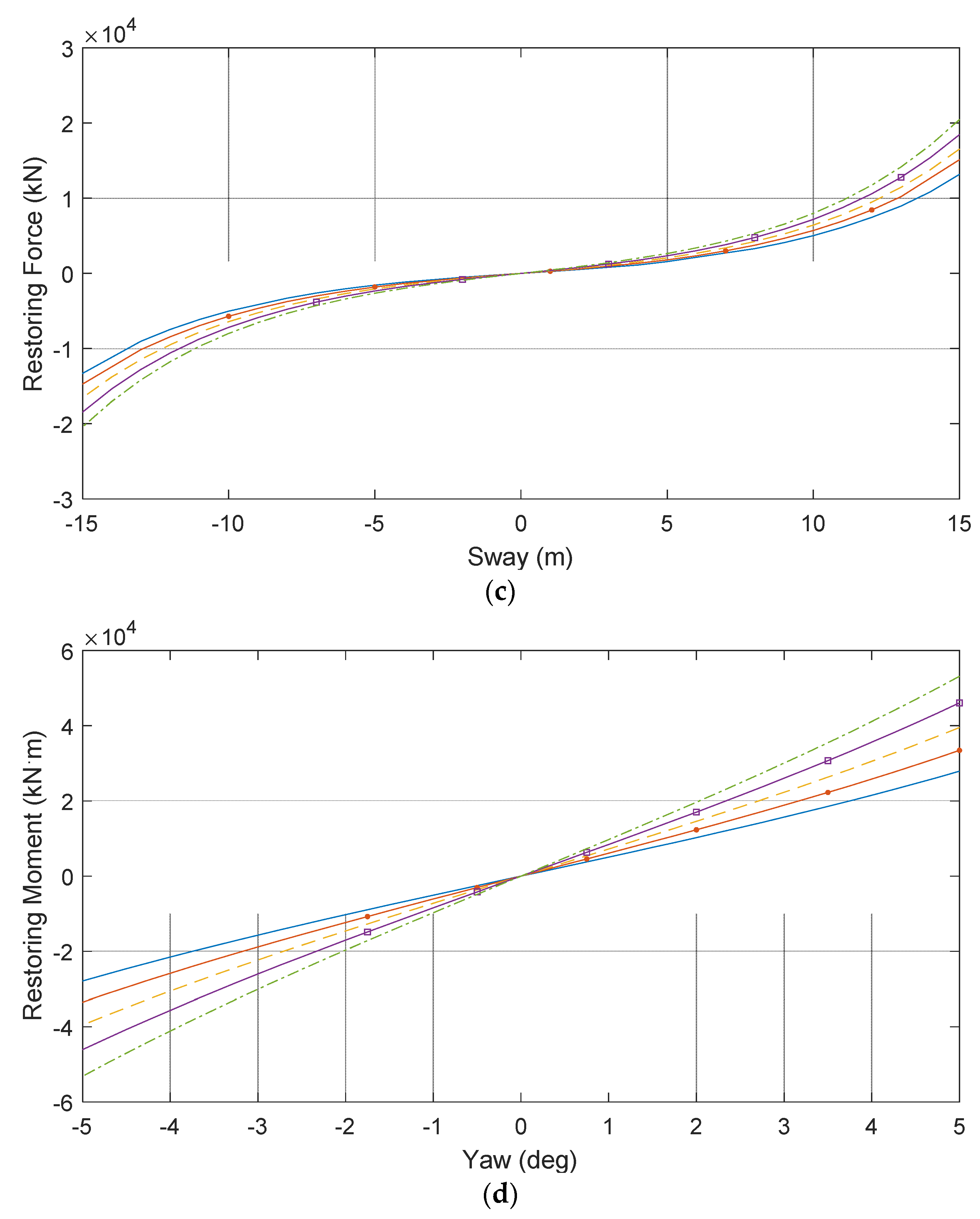
Figure 7.
Effect of length on the static mooring stiffness; (a) Static mooring line configuration; (b) Surge Stiffness; (c) Sway Stiffness; (d) Yaw Stiffness.
Figure 7.
Effect of length on the static mooring stiffness; (a) Static mooring line configuration; (b) Surge Stiffness; (c) Sway Stiffness; (d) Yaw Stiffness.
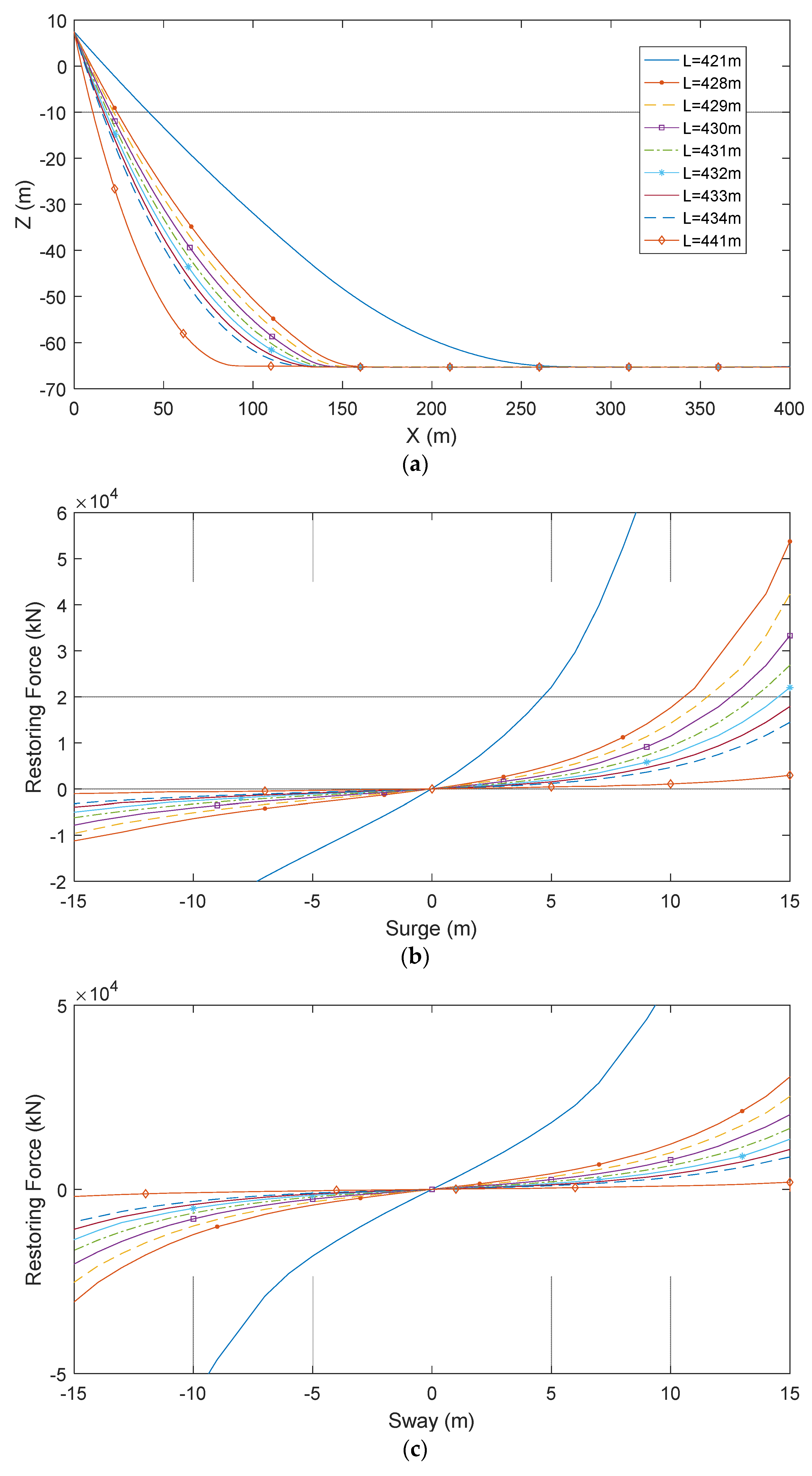

Figure 8.
Time histories of the free decay tests; (a) Surge; (b) Heave; (c) Pitch.
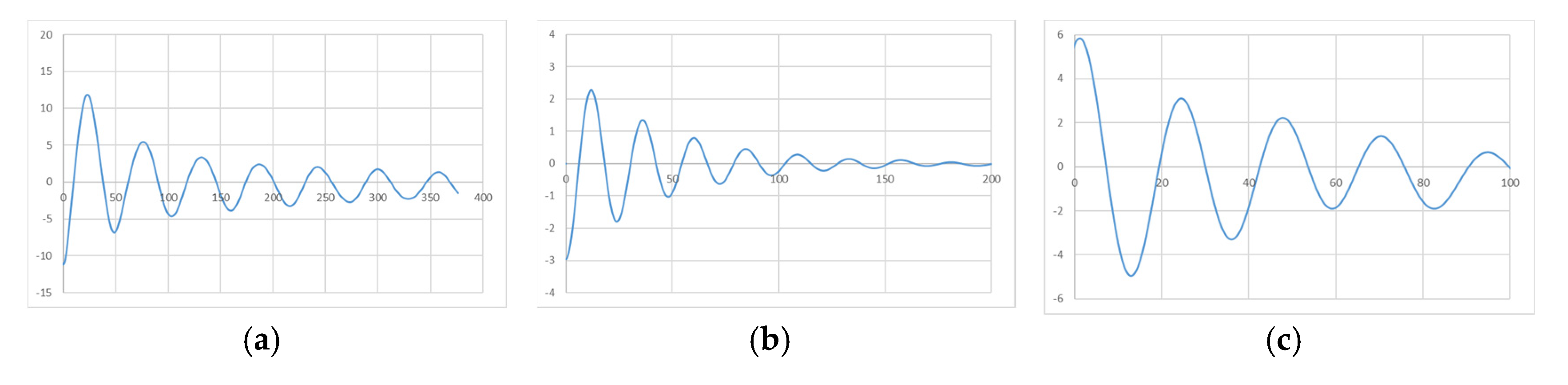
Figure 9.
Time histories of dynamic responses of the semi-submersible FOWT; (a) Surge; (b) Heave; (c) Pitch; (d) Yaw; (e) Mooring line tension.
Figure 9.
Time histories of dynamic responses of the semi-submersible FOWT; (a) Surge; (b) Heave; (c) Pitch; (d) Yaw; (e) Mooring line tension.
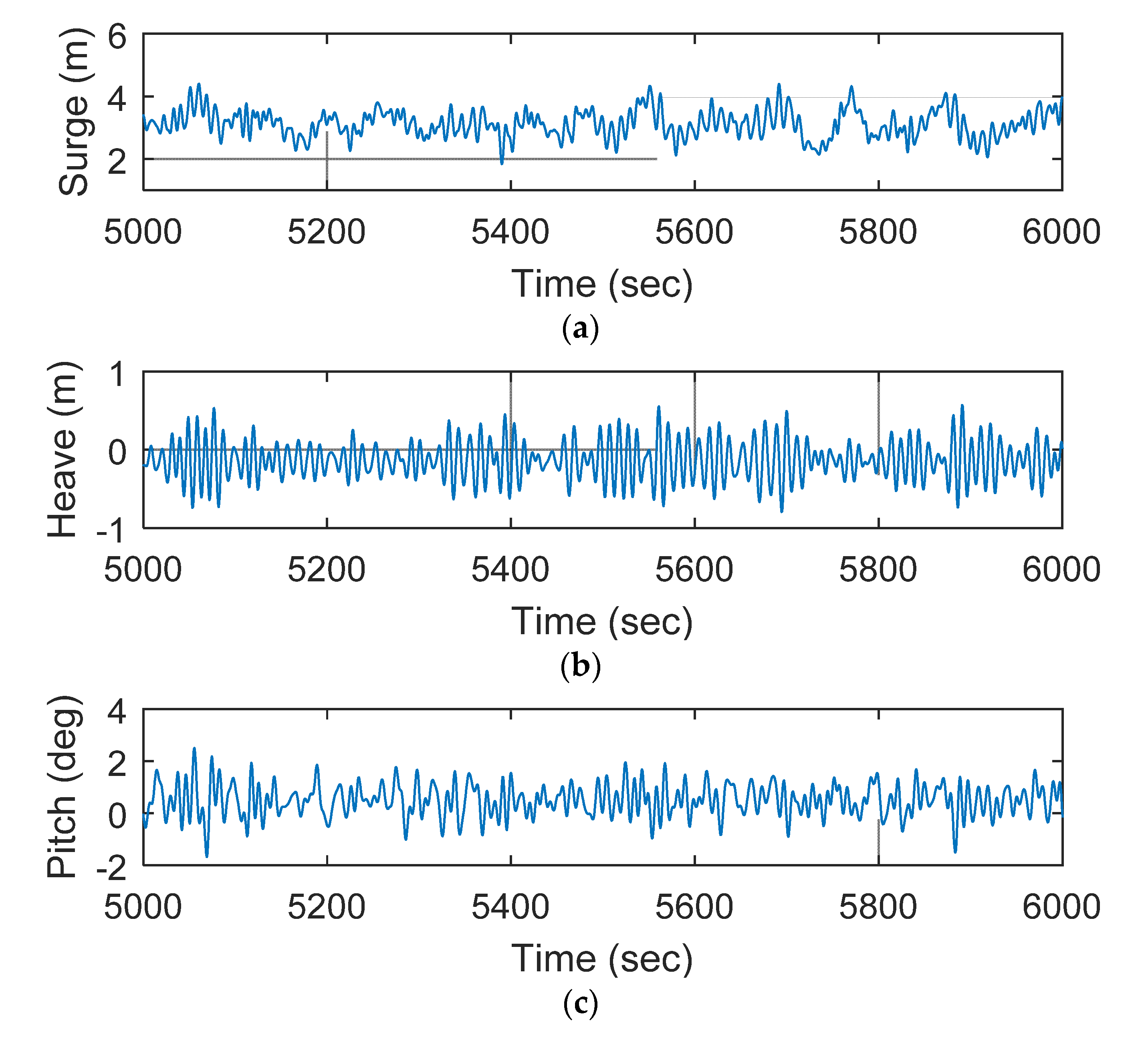
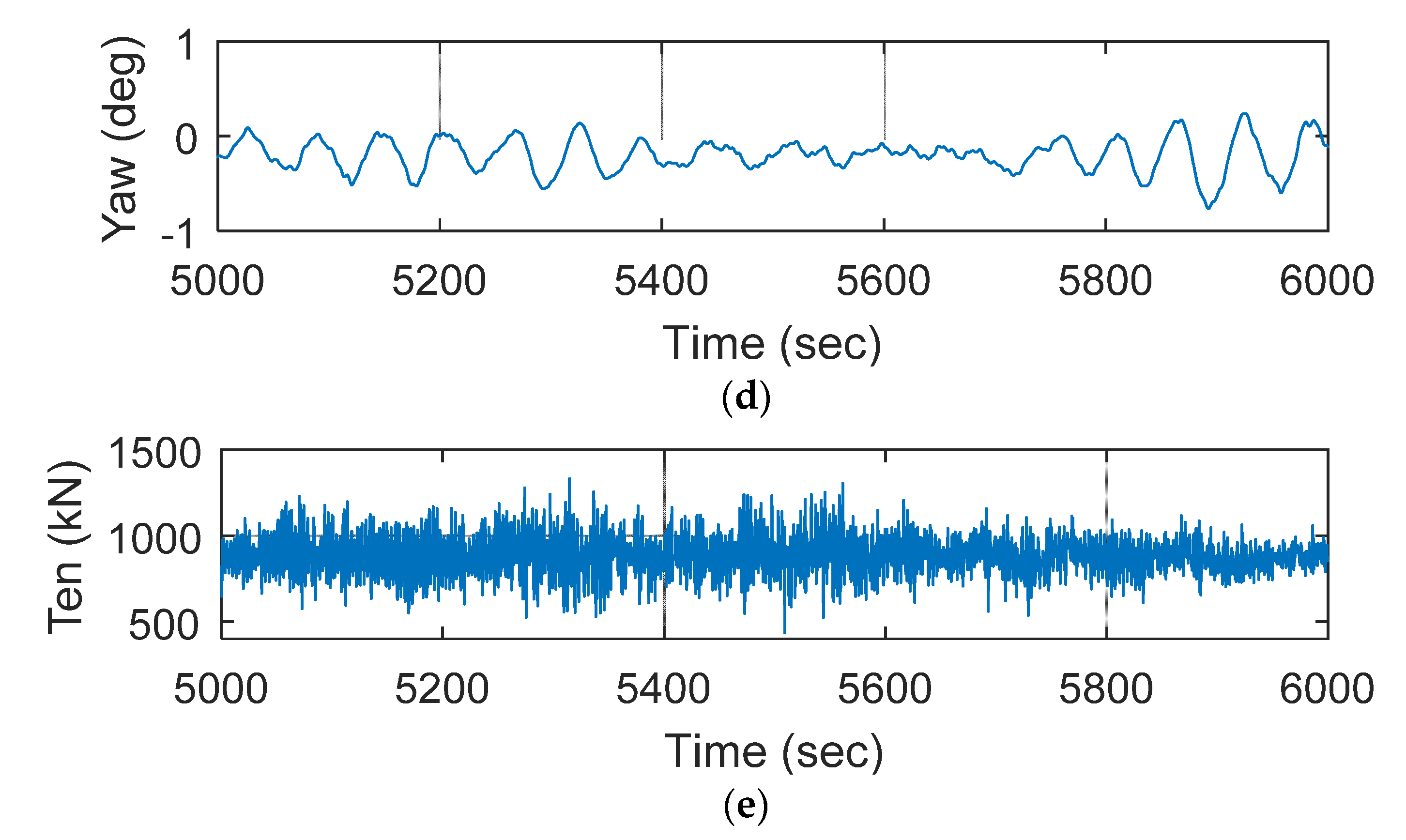
Figure 10.
Statistic results dynamic response of the FOWT with different-diameter mooring lines; (a) Surge; (b) Heave; (c) Pitch; (d) Yaw; (e) Mooring line tension.
Figure 10.
Statistic results dynamic response of the FOWT with different-diameter mooring lines; (a) Surge; (b) Heave; (c) Pitch; (d) Yaw; (e) Mooring line tension.

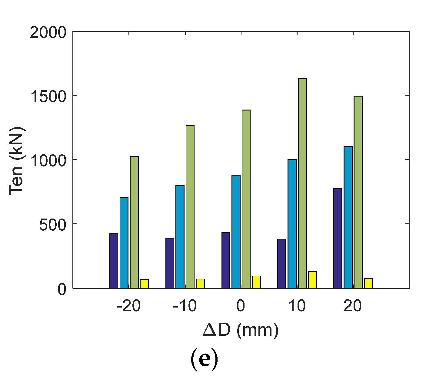
Figure 11.
Statistic results dynamic response of the FOWT with different-length mooring lines; (a) Surge; (b) Heave; (c) Pitch; (d) Yaw; (e) Mooring line tension.
Figure 11.
Statistic results dynamic response of the FOWT with different-length mooring lines; (a) Surge; (b) Heave; (c) Pitch; (d) Yaw; (e) Mooring line tension.

Table 1.
Main parameters of the floating platform.
| Parameter | Value |
|---|---|
| Total length | 71.96 m |
| Total width | 80.0 m |
| Molded depth | 33.0 m |
| Column diameter/spacing | 13.0 m/60.0 m |
| Pontoon width/height | 14.0 m/3.5 m |
| Heave plate diameter/height | 20.0 m/3.5 m |
| Square cross brace length/width/height | 47 m/3.5 m/3.5 m |
| Draft | 18 m |
| Weight | 5621.066 t |
Table 2.
Main parameters of the mooring system.
| Component | S1 (Lowest) | S2 (Middle) | S3 (Upper) |
|---|---|---|---|
| Level | M2 | R3 | R3S |
| Nominal Diameter (mm) | 208 | 122 | 122 |
| Length (m) | 280 | 131 | 20 |
| Dry weight (kg/m) | 861 | 296.2 | 296.2 |
| Minimum broken tension (kN) | 24,140 | 11,365 | 12,690 |
| Axial stiffness (N) | 3.69 × 10⁹ | 1.27 × 10⁹ | 1.27 × 10⁹ |
Table 3.
Natural periods of the FOWT.
| DOF | Natural Period (s) |
|---|---|
| Surge | 53.33 |
| Heave | 24.25 |
| Pitch | 26.43 |
Publisher’s Note: MDPI stays neutral with regard to jurisdictional claims in published maps and institutional affiliations. |
© 2022 by the authors. Licensee MDPI, Basel, Switzerland. This article is an open access article distributed under the terms and conditions of the Creative Commons Attribution (CC BY) license (https://creativecommons.org/licenses/by/4.0/).
Share and Cite
MDPI and ACS Style
Liu, B.; Yu, J. Effect of Mooring Parameters on Dynamic Responses of a Semi-Submersible Floating Offshore Wind Turbine. Sustainability 2022, 14, 14012. https://doi.org/10.3390/su142114012
AMA Style
Liu B, Yu J. Effect of Mooring Parameters on Dynamic Responses of a Semi-Submersible Floating Offshore Wind Turbine. Sustainability. 2022; 14(21):14012. https://doi.org/10.3390/su142114012
Chicago/Turabian StyleLiu, Baolong, and Jianxing Yu. 2022. "Effect of Mooring Parameters on Dynamic Responses of a Semi-Submersible Floating Offshore Wind Turbine" Sustainability 14, no. 21: 14012. https://doi.org/10.3390/su142114012
Note that from the first issue of 2016, this journal uses article numbers instead of page numbers. See further details here.