

Investigating the Effect of Spherical Aluminum Particles on the Photothermal Performance of a Solar Air Collector
1
Faculty of Electronic Information Engineering, Huaiyin Institute of Technology, Huai’an 223003, China
2
Faculty of Mechanical & Material Engineering, Huaiyin Institute of Technology, Huai’an 223003, China
3
Department of Mechanical and Electronic Engineering, Jiangsu Vocational and Technical College of Finance and Economics, Huai’an 223003, China
*
Author to whom correspondence should be addressed.
Sustainability 2022, 14(21), 14107; https://doi.org/10.3390/su142114107
Submission received: 28 August 2022
/
Revised: 20 September 2022
/
Accepted: 29 September 2022
/
Published: 28 October 2022
(This article belongs to the Special Issue Energy-Saving Approaches in Non-Residential Buildings)
Abstract
:Recently, radiation-absorbing phase change material (PCM) for thermal storage that can discharge thermal energy on demand when no radiation is present has been developed and tested indoors. Organic materials with limited thermal conductivity slow down the thermal response processes when charging and discharging. For various industrial applications, much research is devoted to the introduction of solar collectors with the best possible integration of solar thermal collector and PCM in terms of both shape and material. In this study, the performance of a solar collector is examined in relation to the additive effects of aluminum particles in spherical capsules. For the transfer fluid temperature with the behavior of the heat storage, a mathematical model of the solar collector was created. The integrated system consists of two primary steps: a first phase that involves an isolated duct covered in glass, and a second step that involves an array of spherical capsules used as storage. The solar air collector is 1.32 m in width and 2.450 m in length. The PCM unit has a 7.7 cm diameter, 0.15 cm thickness, and is filled with a paraffin wax with concentrations between 0.1 and 0.5 weight of nanoparticle aluminum powder. The air mass flow rate varies from 0.03 kg/s up to 0.09 kg/s, while the temperature varied from 30 to 35 °C. The results obtained from experiments agreed with the predicted results. The reduction in charging time was approximately 70% as the cooling rate increased. The improvement of efficiency of thermal storage reached 76.8% and 71%, at mass flow rates 0.07 kg/s and 0.05 kg/s for pure paraffin wax. The overall thermal storage performance for the system was enhanced from 21.7% to 78.9%.
1. Introduction
Thermal storage is becoming more popular as energy efficiency gains importance on the global stage. From the invention of refrigeration systems, the thermal storage capacity and isolative properties of the earth have been used to keep food and ice cool during the summer in root cellars and ice houses. More recent applications of thermal energy storage include phase change material impregnated wallboard or concrete, seasonal thermal storage and regulation of facility temperatures. Because thermal energy storage has the potential to offer high energy and close to isothermal storage conditions, it may be a desirable method for storing solar thermal energy. Therefore, encapsulating will probably assist to help decrease one’s thermal transfer times intended for PCM [1,2] especially for those materials with lower heat conductivities. Besides, some materials of phase change, such as some eutectic salts or salt hydrates, suffer segregation and sub-cooling problems in the course of thermal cycling [3,4]. Furthermore, encapsulation can assist to mitigate such issues. Moreover, encapsulation might also prevent the EPCM against possible corrosion as well as exposure with thermal transfer fluid. However, materials of encapsulation may lead to other problems, such as machinability for encapsulating materials, compatibility with encapsulation material, etc. During melting-solidification cycling the encapsulation should allow the PCM material for volume change and keep stand the stress. Analysis of stress for different EPCM shapes has been made [5,6,7], a student having master degree who graduated from Lehigh University, Department of Mechanical Engineering for the capsules of EPCM as it was undergoing the alternation of volume due to thermal expansion and change of phase. In (Barreneche et al., 2013) [8], concluded that it is necessary to hold sufficient space in EPCM for minimization of the pressure in it and the maintenance of EPCM’s structural integrity. Such studies also indicated that material of encapsulation must be thick enough to prevent the capsule deformation led by stress put on the shell. There are numerous reports for noting of melting course of mono-component as well as multi-component materials and modelling of solidification. In (Li et al., 2011) [9], utilized front tracking way for the solution of the solidification issue; [10,11,12] the course of solidification in a bi-liquid; (Farid, Khudhair, Razack, Al-Hallaj, 2004; R. Singh, Lazarus, Souliotis, 2016) [13,14] thought the convection at interfaces of crystal and melt. However, not many of such have researched large temperature encapsulated materials for change in phase. Therefore, the current work, which is handling the experiments and the model process of high temperature EPCMs, focuses on these aspects. In addition, many of the PCMS, which may be utilized for low temperature (lower than 120 °C) storage of thermal energy, such as for space heating, etc., have been researched in the last ten years. They may be classified into two types: inorganic and organic hydrates of salts [9,15,16]. Mohammadjavad K. & Sheikholeslami M. [17] investigate the influence of several types of nanofluids and NEPCMs at different concentrations on the system and their efficaciousness is assessed. SiC, ZnO, MCNT (multi-walled carbon nanotube), Al2O3, Cu, and Ag nanoparticles are utilized within water and phase change material. Javad M. et al. [18] investigate the performance of the nano-encapsulated phase change material (NEPCM) slurry in a microchannel heat sink (MCHS) fitted with two circular synthetic jets is examined in this work (SJs). In addition, it focuses on comprehending how key influencing factors, such as NEPCM concentration, frequency, amplitude, inlet velocity, latent heat storage, heat flux, inlet temperature, and phase actuation, affect energy efficiency. Amin et al. [19] investigate the falling patterns of non-circular particles in an enclosure while the pulsatile flow is involved as a counter-flow. Findings were first successfully verified against the existing literature and the accuracy of the results is well-demonstrated. In Behrooz Afra et al. [20] a successful hybrid model is presented for the simulation of flow induced vibrations. The role of flexibility on the filaments flapping in a free-stream at different Reynolds numbers is investigated. Increasing flexibility does not always increase vibration amplitudes and can, surprisingly, decrease fluctuations if flexibility exceeds a specific value. Ali Jalali et al. [21] investigate non-Newtonian flow pattern and heat transfer in an enclosure containing a tilted square. In order to numerically simulate the problem, the mesoscopic lattice Boltzmann method is utilized. It is able to adequately handle the shear-thinning case. Hassan et al. [22] introduce an investigation evaluating the performance of an integrated model of a solar still for the production of potable water using ZnO, Al2O3, TiO2, and CNT nanomaterials. In addition, With and without nanomaterials, the experimental performance of various conventional solar still, flat plate collector, and parabolic trough collector combinations was assessed in terms of water yield and photothermal efficiency. Amjad M. et al. [23] describes some of the cutting-edge nanomaterials and underlying mechanisms that have been exploited to increase solar absorption and, consequently, the effectiveness of direct-absorption solar collectors. Khalil A., et al. [24], introduce comparative analysis to assess the effectiveness of their photothermal performance of a conventional parabolic trough collector and direct absorption parabolic trough collector for capturing solar thermal energy. In addition, to assess the effectiveness of their photothermal performance, a special experimental setup was created with the hybrid nanofluids Al2O3 (with high scattering properties) and CuO (with high absorption properties). Sattar A., et al. [25], presents the photothermal performance of water-based nano-fluids of graphene oxide, zinc oxide, and copper oxide under natural solar flux for the first time. Therefore, currently the work is focused on phase change materials (PCMs) as the latent heat storage for large electrical power generation.
This paper focuses on enhancing the performance of PCM thermal storage spherical capsules with nanoparticle partials. The details of a simulation model for solar collector integrated with PCM have been presented. The experimental and simulation predicted results were compared, including the outlet air temperature during the discharge process, the instantaneous temperature along the collector, and the freezing time. The influences of the operating conditions such as the mass flow rate, the inlet temperature, and the additive mass additive on the thermal discharge process are also discussed. The optimum design conditions for the heat storage unit have been also presented along with the experimental results.
2. Related Work
2.1. Thermal Energy Storage System
Thermal energy can be stored by lowering or increasing the temperature of the substance, such as changing its sensible heat, or changing its latent heat by changing the phase of the substance or combining the two. A thermal energy storage system is a system that stores medium- and low-temperature energy for use in a short period of time. Javad M. et al. [26], in a review of research in the field of thermal energy storage using nano-enhanced phase change materials (NePCM), has revealed a major focus is now on the development of NePCMs. Examples of its main applications are: thermal energy storage systems store solar energy during the day for heating at night, or summer heat for winter use, and winter cooling for summer cooling or heat storage during off-peak hours or cooling capacity for use during peak hours. The thermal energy storage system has the role of allocating energy, and, like solar energy itself and unlike other fossil fuels, it cannot be obtained anytime, anywhere. Due to the influence of time, combining it with a thermal energy storage system can meet the balance between thermal energy demand and thermal energy acquisition. In latent heat storage system, phase change materials have good properties. In the molten state, they can absorb a lot of heat, and in the molten state, the temperature and pressure remain within a certain range [27]. The potential to mitigate many of the technical challenges of PCM-based energy storage systems. In addition, the study also aims to examine the application of NePCMs in LHTES systems. Figure 1 shows the applications of a thermal storage energy system for heating, cooling, and electricity generation [28].
2.2. Structural of Phase Change Material Microcapsules
The phase change materials can be effectively combined with nanoparticles through coating or capsule technology to make them smart materials with temperature adjustment function. Therefore, encapsulation of phase change materials is a good choice for architectural applications, as shown in Figure 2.
3. Solar Collector System Mathematical Model
Figure 3 shows the collector system configuration diagram of the design for solar air collectors, including the collector length (L), the width (W), and the duct depth (Z). This system primarily consists of three parts: a single transparent glass, an isolated duct, and a storage unit made up of several rows of spherical PCM arranged in a crossflow of forced air. This unit serves the dual purposes of absorbing and storing solar energy.
The capacity of storage of heat storage latent system with a medium of PCM [29,30] is obtained from:
where Tf: flow temperature; : specific heat;
Thermal Transfer Factor (HTF):
where x: Storage tank’s axial direction; ε: Void fraction; Vmax: HTF velocity; hs: thermal transfer coefficient on the surface between PCM and HTF; L: The storage tank height; : The storage tank cross sectional area; : density; hw: Heat transfer; hs: surface heat transfer coefficient between HTF and PCM.
For PCM:
where qsolar: solar radiation flux; : Stefan-Boltzmann constant (5.67 × 10⁻⁸), and where a typical value for solar radiation flux is 1.140 Wm−2.
The performance of heat energy storage systems may be defined, based on first-law efficiency, as the ratio of energy that is extracted from that of the energy’s storage. With regards to a charge or discharge process, the coefficient is denoted as
where η is the TES efficiency; td is the temperature difference that has been decreased over 20%, i.e., ( < 0.8 |); ms, Cs and mf, Cf are the storage medium and the working fluid’s total thermal capacity respectively; T, is the storage’s lowest and T highest temperatures during the charging and discharging period.
The solution procedures divide the system into three essential portions which are: the storage unit, which includes a single-row of spherical including a PCM, isolated duct, and a single transparent glass. With a spherical object put in the forced air stream’s cross flow, the unit works for the satisfaction of two objectives: storage and absorbing the energy of the sun.
Initial Conditions
Boundary conditions
Governing equations:
Re-arranging Equations (2) and (3) to governing equations as follows:
The freezing time for each capsule is different from the other capsules, and this operation can be imagined as being simulated. The method of orthogonal collocation (OC), a type of discretization methods known as the method of weighted residuals, is popular as it is easy to apply; detailed information is given by (Wang et al., 1991; Yang et al., 2011; Zhao et al., 2015) [31,32,33].
The experimental measurement of material characteristics is the primary cause of uncertainty in these variables. The bigger figure of 5% was taken into account in this investigation because the normal uncertainty when measuring the density and the specific heat of a PCM is between 3–5%. Experimental mistakes may also affect the PCM melting temperature, and a Tmelt uncertainty of 1 °C was assumed. At the HTF bulk temperature, the properties of the HTF were thought to be the same as those of paraffin wax, however it should be noted that, since the HTF contains aluminum additions in low percentages, they may differ. Since these uncertainties are unknown a priori, the same inaccuracy of about 5% of the parameter value as for the PCM properties was taken into account. According to Pablo Dolado et al. (2012), the bulk temperature of the HTF affects the HTF’s characteristics, including density and specific heat
where THTF;out;old is the HTF’s outlet temperature and THTF;in is the current iteration’s inlet temperature.
When the relative error, rather than the absolute magnitude of the variable error, is what is important, the maximum absolute peak error (MAPE) measure can be helpful. Since the heat transfer rate is the primary output parameter in our example and was used to calculate the accuracy of the simulated heat transfer, the evaluation of the MAPE using this parameter is of particular importance:
where is the capacity of storage of heat.
4. Result and Discussion
The structure of the thermal air collector being measured is shown in Table 1 while the thermophysical parameters of the PCM are shown in Table 2, and the physical parameters of the packets are shown in Table 3.
The thermocouple’s location in the collector to monitor the actual and accurate air temperature is shown in Figure 4. The simulation program was written using CFD software using GAMIT software to determine the outlet air temperature as well as the discharge time for the heater of solar air integrated using the PCM spherical capsules with any input parameters changes [34,35]. The model with boundary conditions was converted to algebraic equations by means of finite-volume techniques with fully implicit temporal differentiation, using three-dimensional spherical capsule in a staggered arrangement. The delusive terms were evaluated using central differences scheme as shown in Figure 4.
From Figure 5a,b, with increasing Re = 42,751 both airflows will increase min = 0.524 to max = 1.34 m/s to and temperature will increase from 26.8 to 70.9 °C.
The experimental investigation has been divided into four steps. While the first one deals with analyzing the effect of the mass flow rate on the outlet temperature and the discharge time, the second step is the analysis of the effect of the aluminum mass additive on the outlet and the PCM temperature. The third step analysis also elaborates on the effect of the additive on the cooling rate. In order to determine the discharge time and the heat exchange between the PCM capsules and the air in the collector, the fourth stage intelligent modeling predicated outlet temperature and the air temperature within the collector throughout the discharge process have been examined. Moreover, the comparison between the theoretical and experimental results between the pure paraffin wax and the compound of 0.5% aluminum powder has been also achieved.
In general, when the mass flow rate increased, the instantaneous rising in the air temperature decreased while the heat exchanging after the capsule number T14 became low for the inlet temperature 30 °C, the air temperature became stable, and the heat exchanging became low after capsule T5 for the inlet temperature 30 °C as shown in Figure 6. Along with (t = 100 min) the air collector was integrated with the PCM unit for different mass flow rates.
The results were recorded for more comparisons in Table 4 and Table 5 for experimental and the corresponding theoretical temperatures of the air along the collector at constant inlet temperature (30 °C and 35 °C).
The results of this study from the experiments agree fairly well with the RMS error of 0.78 °C expected findings and are summarized in Table 5.
The aluminum powder was added to the paraffin wax for enhancing the heat transfer. To optimize the suitable aluminum mass additive in the capsules, the additive masses of the aluminum powder were examined as follows: 0.1, 0.2, 0.3, 0.4, 0.5, 0.6, and 0.7. Additionally, an additional mass ratio of 0.5% produced the best results for the solidification time. The impact of the additive ratio will be examined in the section after this one. The mass and volume of the paraffin wax and the aluminum powder ratios in the capsule are shown in Table 6.
Figure 7 shows the inlet temperature was 30 °C and the storage material was the pure paraffin wax, the temperature rise (To − Tin) decreased from 15.57 °C to 11.13 °C at the mass flow rate of 0.01 kg/s the mass flow rate of 0.09 kg/s. After adding 0.5% aluminum powder, the temperature rise decreased from 16.57 °C at the mass flow rate of 0.01 kg/s to 12.2 °C at the mass flow rate of 0.09 kg/s.
The optimizing additive ratio was increased from 0.1% to 0.7% to check the suitable mass additive so that it could be used with paraffin wax. Figure 8 shows that an increase in the mass additive will result in an increase in cooling rate and an improvement in discharge time. The PCM appeared to behave as a sensible storage material that would reflect on the outlet air temperature for the mass additive 0.6%, but the solidification time also decreased and the cooling rate increased. As a result, the mass additive of 0.5%, which was used in the majority of our experiments, produced the best results.
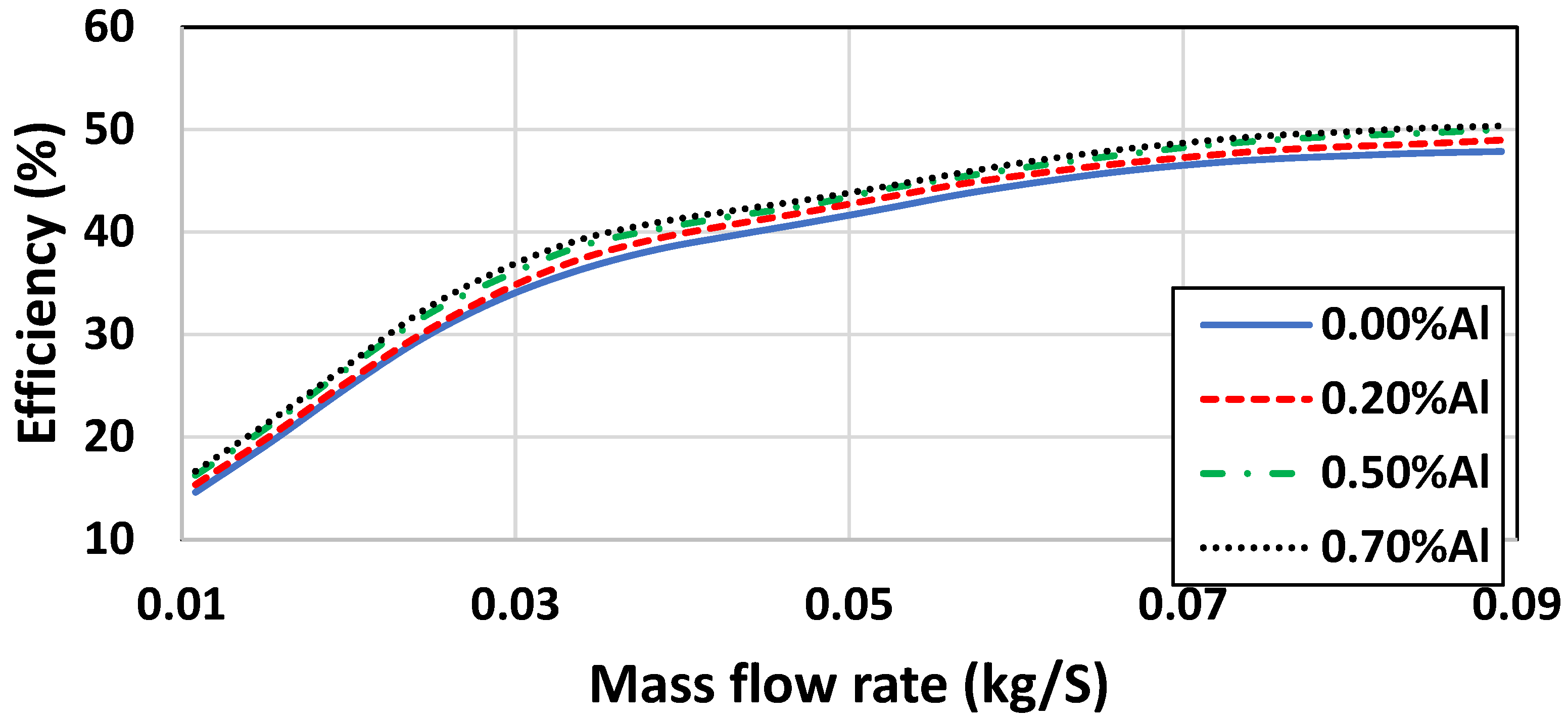
Figure 9 illustrates the performance of the thermal storage system in an additive ratio at a certain time (t = 100 min). The thermal storage efficiency was determined for various mass flow rates and various aluminum ratios. The tested mass additives in the PCM-aluminum compound material were 0.1, 0.2, 0.3, 0.4, and 0.5 of aluminum. The temperature of the outlet air and the system’s solar thermal efficiency were also tested. The thermal storage capacity for the pure paraffin wax and the compound was 71%, and 76.8% of the mass flow rates 0.05 kg/s and 0.07 kg/s, respectively. So, the mass flow rate of 0.05–0.09 kg/s did not drastically affect the thermal storage efficiency.
The overall thermal storage performance for the system enhanced from 21.7% to 78.9%. It was evaluated as the integration of the thermal storage efficiencies during drastically time intervals of t = 25 min; when the mass flow rate was 0.07 kg/s, the ambient temperature and inlet temperature were around 30 °C.
Table 7 demonstrates that the inlet HTF temperature THTF;in, which is significant for obtaining an accurate estimate of the heat transfer rate over the discharging period, corresponds to the maximum MAPE with respect to the reference scenario. Direct measurement of THTF;in can yield this profile, and if the “precise” observed values fall within the 1oC uncertainty interval of the linear dependence shown in Equation (11), one should anticipate deviations for MAPE that are fewer than the values reported in Table 7.
5. Conclusions
This study describes the experimental and theoretical investigations of integrated thermal storage unit with a solar air collector. These capsules were tested as an absorber in the collector, and to store the thermal energy. The additive ratio increased from 0.1% to 0.6% mass fraction to optimize the suitable ratio which can be used in the compound. The cooling rate increased as observed here; henceforward, it can be noted from the results that an increase in the mass fraction will increase the cooling rate and improve the discharge time. From the mass fraction 0.6% and up the cooling rate increased but the solidification time became short which will reflect on the outlet air temperature; consequently, the best result appeared with the mass fraction 0.5% which was used in most of our experiments. It was experimentally confirmed that charging time was reduced by almost 60% with the paraffin wax-aluminum composite. The thermal responses for the charging or discharging processes were improved, too. In addition, the aluminum was used as an additive material because it has moderate thermal conductivity property and cheap cost in the market compared to copper. The moderate thermal conductivity is preferred because the thermal conductivity of the copper is 390 W/m·k while for the aluminum it is 200 W/m·k. The nanoparticle additive makes the PCM discharge the thermal energy faster and reduce the discharge time. The limitation of this model was air leakage for the side edge of the solar collector which, affects the convection coefficient between HTF and wall surface, and slab wall thermal conductivity, and can be further investigated.
Author Contributions
Conceptualization and write the first draft, C.L.; Formal analysis, Y.D.; Investigation, X.F.; Methodology, Y.W.; Software, Q.Z. All authors have read and agreed to the published version of the manuscript.
Funding
This research received no external funding.
Institutional Review Board Statement
Not applicable.
Informed Consent Statement
Not applicable.
Data Availability Statement
Data is confidential.
Acknowledgments
The listed author(s) are highly grateful to HuaiYin institute of technology for providing financial.
Conflicts of Interest
The authors declare no conflict of interest.
References
- Sheikholeslami, M. Influence of magnetic field on Al2O3-H2O nanofluid forced convection heat transfer in a porous lid driven cavity with hot sphere obstacle by means of LBM. J. Mol. Liq. 2018, 263, 472–488. [Google Scholar] [CrossRef]
- Yun, J.H.; Kim, J.H.; Jeong, S.Y.; Yang, Y.S.; Kim, S.H.; Song, D.Y. An Experimental Study on the Freezing Protection Valve Using Phase Change Material (PCM) for the Heat Exchanger. J. Korean Sol. Energy Soc. 2012, 32, 127–133. [Google Scholar] [CrossRef] [Green Version]
- Alkan, C.; Günther, E.; Hiebler, S.; Ensari, Ö.F.; Kahraman, D. Polyethylene glycol-sugar composites as shape stabilized phase change materials for thermal energy storage. Polym. Compos. 2012, 33, 1728–1736. [Google Scholar] [CrossRef]
- Ode, M.; Kim, S.G.; Suzuki, T. Recent advances in the phase-field model for solidification. ISIJ Int. 2001, 41, 1076–1082. [Google Scholar] [CrossRef]
- Bhrawy, A.; Zaky, M.A. A method based on the Jacobi tau approximation for solving multi-term time–space fractional partial differential equations. J. Comput. Phys. 2015, 281, 876–895. [Google Scholar] [CrossRef]
- Kürklü, A.; Özmerzi, A.; Bilgin, S. Thermal performance of a water-phase change material solar collector. Renew. Energy 2002, 26, 391–399. [Google Scholar] [CrossRef]
- Wu, S.; Yan, T.; Kuai, Z.; Pan, W. Thermal conductivity enhancement on phase change materials for thermal energy storage: A review. Energy Storage Mater. 2019, 25, 251–295. [Google Scholar] [CrossRef]
- Barreneche, C.; Solé, A.; Miró, L.; Martorell, I.; Fernández, A.I.; Cabeza, L.F. Study on differential scanning calorimetry analysis with two operation modes and organic and inorganic phase change material (PCM). Thermochim. Acta 2013, 553, 23–26. [Google Scholar] [CrossRef]
- Li, M.; Wu, Z.; Kao, H.; Tan, J. Experimental investigation of preparation and thermal performances of paraffin/bentonite composite phase change material. Energy Convers. Manag. 2011, 52, 3275–3281. [Google Scholar] [CrossRef]
- Abuşka, M.; Şevik, S.; Kayapunar, A. A comparative investigation of the effect of honeycomb core on the latent heat storage with PCM in solar air heater. Appl. Therm. Eng. 2019, 148, 684–693. [Google Scholar] [CrossRef]
- Mirković, D.; Gröbner, J.; Schmid-Fetzer, R. Solidification paths of multicomponent monotectic aluminum alloys. Acta Mater. 2008, 56, 5214–5222. [Google Scholar] [CrossRef]
- Miyamoto, J.; Sassa, S.; Sekiguchi, H. Progressive solidification of a liquefied sand layer during continued wave loading. Geotechnique 2004, 54, 617–629. [Google Scholar] [CrossRef]
- Farid, M.M.; Khudhair, A.M.; Razack, S.A.K.; Al-Hallaj, S. A review on phase change energy storage: Materials and applications. Energy Convers. Manag. 2004, 45, 1597–1615. [Google Scholar] [CrossRef]
- Singh, R.; Lazarus, I.J.; Souliotis, M. Recent developments in integrated collector storage (ICS) solar water heaters: A review. Renew. Sustain. Energy Rev. 2016, 54, 270–298. [Google Scholar] [CrossRef]
- Cui, X.; Chen, K.; Xing, H.; Yang, Q.; Krishna, R.; Bao, Z.; Han, Y. Pore chemistry and size control in hybrid porous materials for acetylene capture from ethylene. Science 2016, 353, 141–144. [Google Scholar] [CrossRef]
- Glasser, L. Thermodynamics of inorganic hydration and of humidity control, with an extensive database of salt hydrate pairs. J. Chem. Eng. Data 2014, 59, 526–530. [Google Scholar] [CrossRef]
- Mohammadjavad, K.; Sheikholeslami, M. Heat transfer efficiency and electrical performance evaluation of photovoltaic unit under influence of NEPCM. Int. J. Heat Mass Transf. 2022, 183, 122232. [Google Scholar]
- Javad, M.; Ann, L.; Victoria, T.; Robert, T. Nano-Enhanced Phase Change Materials for Thermal Energy Storage: A Bibliometric Analysis. Energies 2022, 15, 3426. [Google Scholar]
- Amin, A.D.; Sajjad, K.; Fuli, H. Direct Numerical Simulation of pulsating flow effect on the distribution of non-circular particles with increased levels of complexity: IB-LBM. Comput. Math. Appl. 2022, 121, 115–130. [Google Scholar]
- Behrooz, A.; Amin, A.D.; Mostafavi, M.; Ali, T. Fluid-structure interaction for the flexible filament’s propulsion hanging in the free stream. J. Mol. Liq. 2021, 323, 114941. [Google Scholar]
- Ali, J.; Amin, A.D.; Mojtaba, K.; Golmohamadi, A.M.; Sajjad, K. Mesoscopic Simulation of Forced Convective Heat Transfer of Carreau-Yasuda Fluid Flow over an Inclined Square. Temp.-Depend. Viscosity 2020, 6, 307–319. [Google Scholar]
- Hassan, H.M.A.; Amjad, M.; Qamar, A.; Noor, F.; Hu, Y.; Yaqub, T.B. Performance analysis of nanofluid-based water desalination system using integrated solar still, flat plate and parabolic trough collectors. J. Braz. Soc. Mech. Sci. Eng. 2022, 44, 427. [Google Scholar] [CrossRef]
- Amjad, M.; Haruna, M.A.; Gardy, J. Chapter two–Nanomaterials for solar energy capture and steam generation. In Emerging Nanotechnologies for Renewable Energy, Micro and Nano Technologies; Elsevier: Amsterdam, The Netherlands, 2021; pp. 37–48. [Google Scholar]
- Khalil, A.; Amjad, M.; Noor, F.; Hussain, A.; Nawaz, S.; Du, X. Performance analysis of direct absorption-based parabolic trough solar collector using hybrid nanofluids. J. Braz. Soc. Mech. Sci. Eng. 2020, 42, 573. [Google Scholar] [CrossRef]
- Sattar, A.; Farooq, M.; Amjad, M.; Saeed, M.A.; Nawaz, S.; Mujtaba, M.A.; Anwar, S.; El-Sherbeeny, A.M.; Soudagar, M.E.M.; Bandarra Filho, E.P.; et al. Performance Evaluation of a Direct Absorption Collector for Solar Thermal Energy Conversion. Energies 2020, 13, 4956. [Google Scholar] [CrossRef]
- Javad, M.; Fatemeh, S.; Ann, L. Performance of nano encapsulated phase change material slurry heat transfer in a microchannel heat sink with dual-circular synthetic jets. Int. J. Heat Mass Transf. 2022, 184, 122265. [Google Scholar]
- Rathod, M.K.; Banerjee, J. Thermal stability of phase change materials used in latent heat energy storage systems: A review. Renew. Sustain. Energy Rev. 2013, 18, 246–258. [Google Scholar] [CrossRef]
- Gürel, B. A numerical investigation of the melting heat transfer characteristics of phase change materials in different plate heat exchanger (latent heat thermal energy storage) systems. Int. J. Heat Mass Transf. 2020, 148, 119117. [Google Scholar] [CrossRef]
- Sheikholeslami, M.; Ghasemi, A.; Li, Z.; Shafee, A.; Saleem, S. Influence of CuO nanoparticles on heat transfer behavior of PCM in solidification process considering radiative source term. Int. J. Heat Mass Transf. 2018, 126, 1252–1264. [Google Scholar] [CrossRef]
- Pablo, D.; Javier, M.; Ana, L.; José, M.M.; Belén, Z. Experimental validation of a theoretical model: Uncertainty propagation analysis to a PCM-air thermal energy storage unit. Energy Build. 2012, 45, 124–131. [Google Scholar]
- Wang, Y.; Weidner, D.J.; Liebermann, R.C.; Liu, X.; Ko, J.; Vaughan, M.T.; Pacalo, R.E. Phase transition and thermal expansion of MgSiO3 perovskite. Science 1991, 251, 410–413. [Google Scholar] [CrossRef]
- Yang, Z.; Yao, Z.; Li, G.; Fang, G.; Nie, H.; Liu, Z.; Huang, S. Sulfur-doped graphene as an efficient metal-free cathode catalyst for oxygen reduction. ACS Nano 2011, 6, 205–211. [Google Scholar] [CrossRef] [PubMed]
- Zhao, Y.Y.; Hu, F.X.; Bao, L.F.; Wang, J.; Wu, H.; Huang, Q.Z.; Kuang, H. Giant negative thermal expansion in bonded MnCoGe-based compounds with Ni2In-type hexagonal structure. J. Am. Chem. Soc. 2015, 137, 1746–1749. [Google Scholar] [CrossRef] [PubMed]
- Singh, S.; Kumar, K. A Study on Solar Water Heater Based On Phase Change Material. Int. J. Eng. Manag. Res. 2016, 6, 504–508. [Google Scholar]
- Solomon, L.; Elmozughi, A.F.; Oztekin, A.; Neti, S. Effect of internal void placement on the heat transfer performance–Encapsulated phase change material for energy storage. Renew. Energy 2015, 78, 438–447. [Google Scholar] [CrossRef]
Figure 1.
Application of thermal energy storage system.
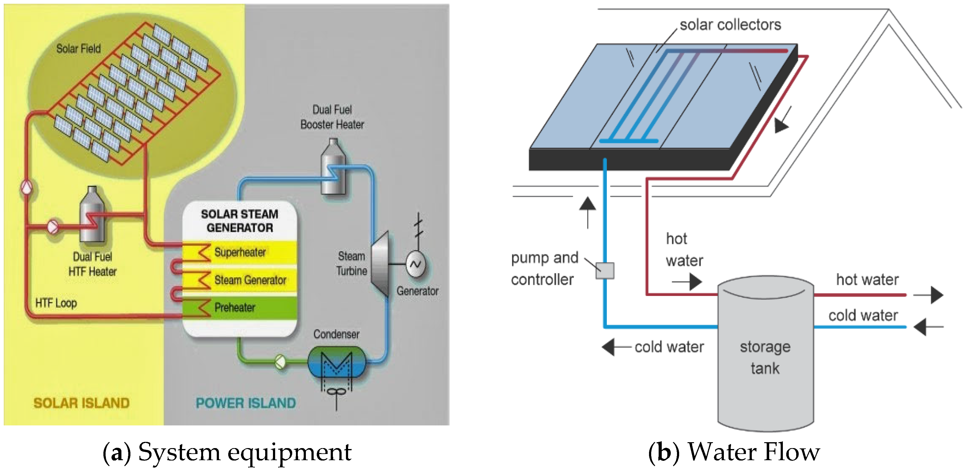
Figure 2.
The structure of phase change material microcapsules.

Figure 3.
PCM spheres and solar air collector cross section.

Figure 4.
CFD simulation mode.
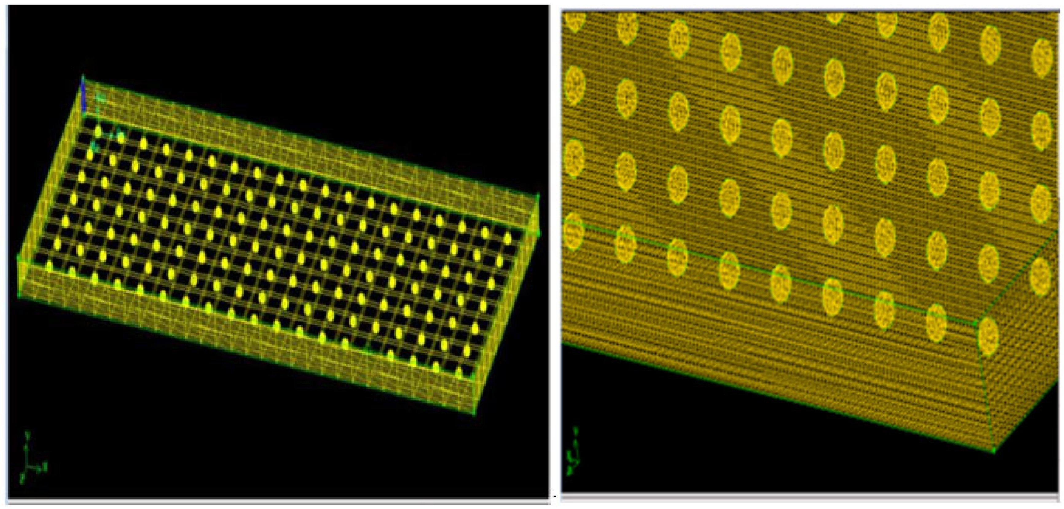
Figure 5.
Simulation model using GAMBIT software. (a) Velocity magnitude along the solar collector (b) Temperature distribution along the solar collector.
Figure 5.
Simulation model using GAMBIT software. (a) Velocity magnitude along the solar collector (b) Temperature distribution along the solar collector.
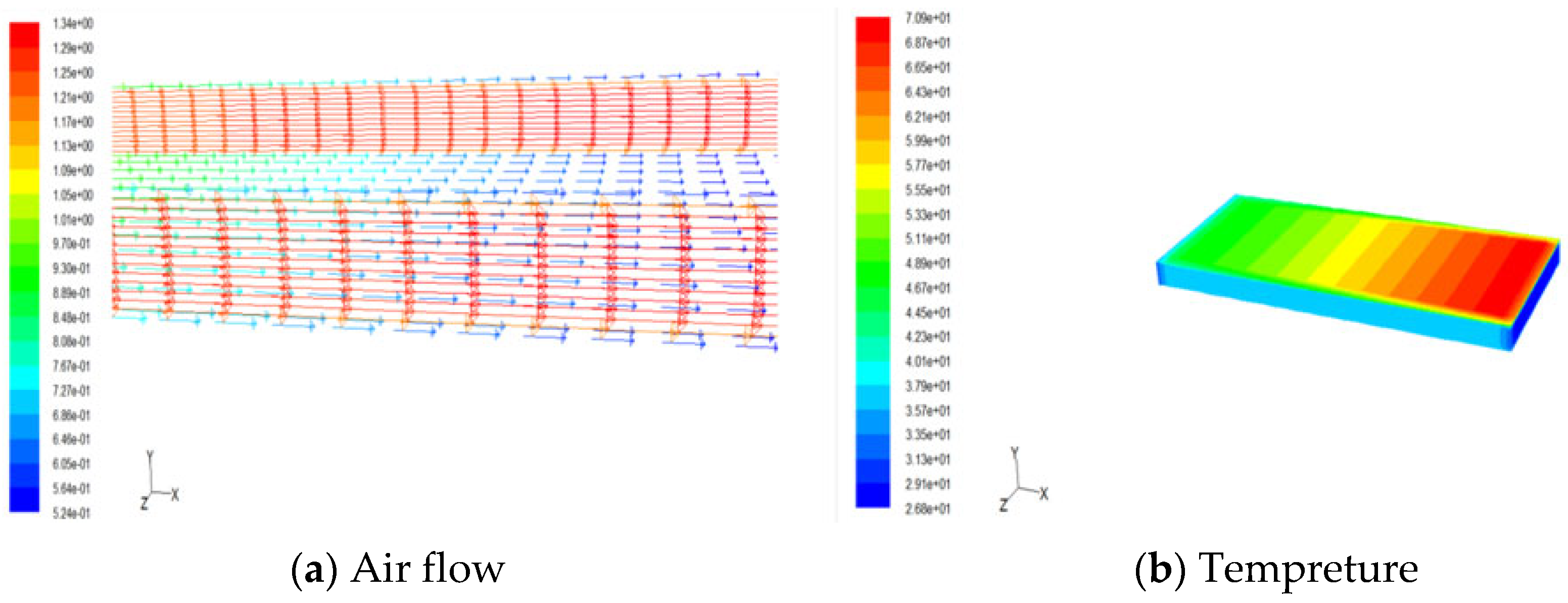
Figure 6.
The output air temperature with different mass flow rates along the duct at Tin = 30 °C.
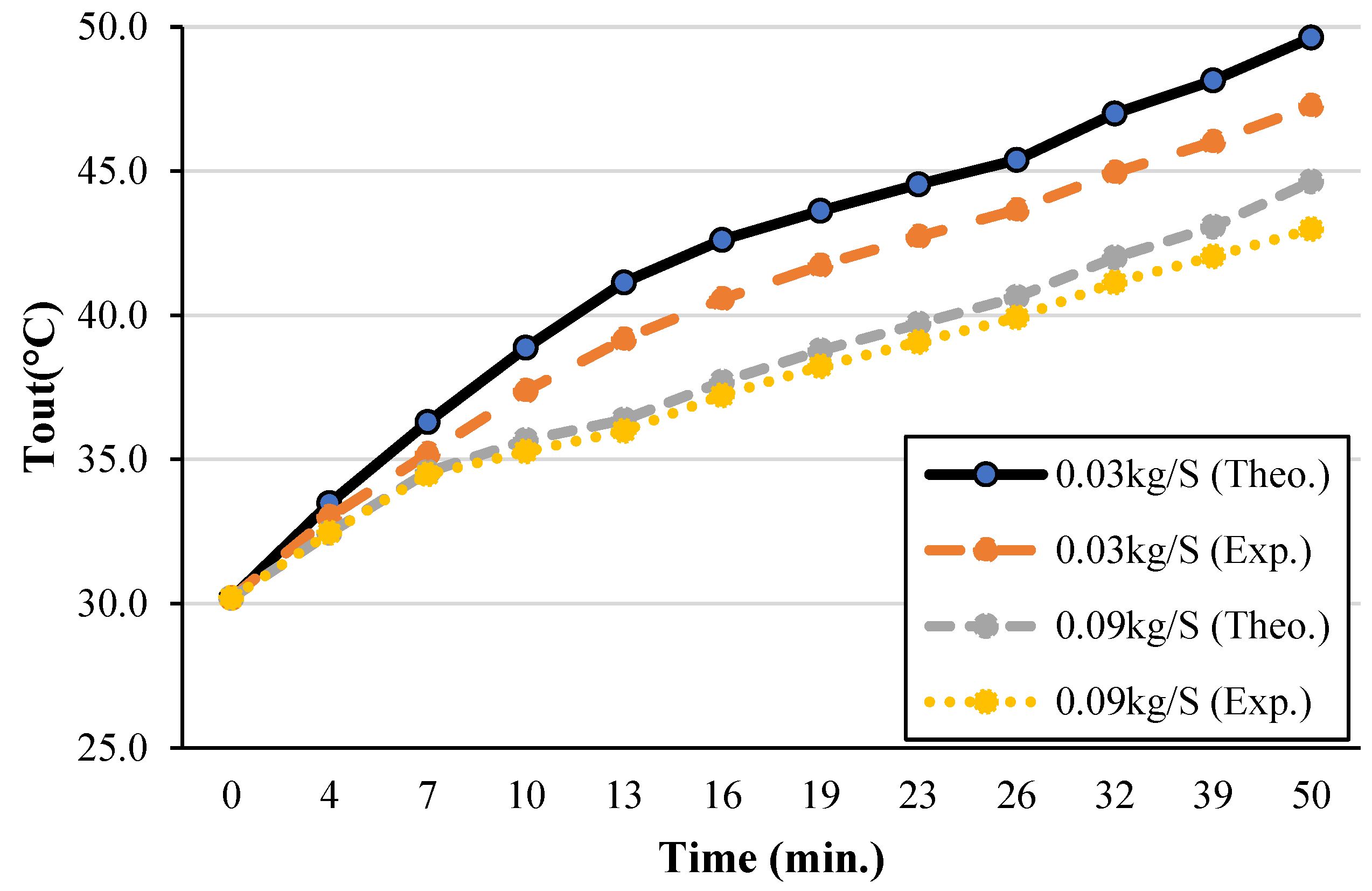
Figure 7.
The relationship between temperature and mass flow rates at [Tin = 30 °C].

Figure 8.
The PCM the solidification process with time for at various aluminum additive mass (m = 0.03 kg/s and Tin = 30 °C).
Figure 8.
The PCM the solidification process with time for at various aluminum additive mass (m = 0.03 kg/s and Tin = 30 °C).

Figure 9.
The relationship between thermal storage efficiency and mass flow rate at Tin = 35 °C with different aluminum ratios.
Figure 9.
The relationship between thermal storage efficiency and mass flow rate at Tin = 35 °C with different aluminum ratios.

Table 1.
The solar collector Physical dimensions.
| Collector Information | Value (cm) |
|---|---|
| Collector Height | 15 |
| Collector Width | 109.6 |
| Collector Length | 234.9 |
| Effective glazing area | 194.9*107 |
| Glass thickness | 0.4 cm |
Table 2.
Paraffin wax material thermos physical properties.
| Property | Value |
|---|---|
| Liquid density | 770 kg/m3 |
| Specific heat | 2.5 kJ/Kg·K |
| Thermal conductivity | 0.2 W/m·K |
| Melting temperature | 51–54 °C |
| Latent heat of fusion | 189 kJ/kg |
| Capsule surface absorbance | 0.97 |
| Kinematic viscosity | 3.3–3.6 mm2/s at 373 K |
Table 3.
Capsules physical dimensions.
| Spherical Capsule | Value |
|---|---|
| Diameter | 7.7 cm |
| thickness | 0.15 cm |
| Weight of capsules | 0.05 kg |
| Material | PVC, polyethylene or Cupper (Any of this) |
| Number of capsules | 152 |
| No. of rows | 10 |
| No. of spherical cap in each row | 7 |
| Gaps between each row | 2–4 cm |
Table 4.
Instantaneous air temperature along the duct at various mass flow rates [Tin = 35 °C].
| N | (kg/S) | |||||||
|---|---|---|---|---|---|---|---|---|
| 0.03 | 0.05 | 0.07 | 0.09 | |||||
| Exp (T °C) | Theo (T °C) | Exp (T °C) | Theo (T °C) | Exp (T °C) | Theo (T °C) | Exp (T °C) | Theo (T °C) | |
| T2 | 35.13 | 35 | 35.15 | 35 | 35.25 | 35 | 35.14 | 35 |
| T5 | 46.99 | 43.79 | 45.02 | 42.536 | 44.02 | 42.06 | 43.02 | 41.72 |
| T8 | 50.43 | 48.52 | 48.81 | 47.186 | 48.15 | 46.62 | 47.14 | 46.20 |
| T11 | 52.20 | 50.94 | 50.36 | 49.77 | 49.79 | 49.28 | 48.66 | 48.10 |
| T14 | 52.81 | 52.32 | 50.91 | 50.36 | 50.21 | 50.09 | 49.71 | 49.31 |
Table 5.
The Air Temperature rise of the solar air collector integrated with the PCM unit at various mass flow rates v (Tin = 30 °C) and (Tin = 35 °C).
Table 5.
The Air Temperature rise of the solar air collector integrated with the PCM unit at various mass flow rates v (Tin = 30 °C) and (Tin = 35 °C).
| (kg/S) | Tin = 30 °C | Tin= 35 °C | ||
|---|---|---|---|---|
| Exp(To − Tin) | The(To − Tin) | Exp(To − Tin) | The(To − Tin) | |
| 0.01 | 15.98 | 15.13 | 18.56 | 17.65 |
| 0.03 | 14.82 | 13.64 | 16.68 | 17.81 |
| 0.05 | 12.45 | 12.04 | 15.53 | 15.91 |
| 0.07 | 11.81 | 10.93 | 14.83 | 15.211 |
| 0.09 | 10.11 | 10.07 | 14.23 | 14. 31 |
Table 6.
The Mass and volume ratios of the paraffin wax, nanoparticle, and the new compound.
| Mass Additive MAl (%) | Val. Additive Al (%) | Val. P.W (%) | Mass of Al (g) | Mass of P.W (g) | Mass of Compound (g) |
|---|---|---|---|---|---|
| 0.1 | 0.349 | 99.97 | 1.14 | 1138.86 | 1140 |
| 0.2 | 0.697 | 99.94 | 2.28 | 1137.72 | 1140 |
| 0.3 | 1.044 | 99.91 | 3.42 | 1136.58 | 1140 |
| 0.4 | 1.389 | 99.89 | 4.56 | 1135.44 | 1140 |
| 0.5 | 1.732 | 99.86 | 5.7 | 1134.30 | 1140 |
Table 7.
Uncertainties effect on average heat transfer rate and energy storage deviations.
| Variable | Reference Value | Measured Value | Qaverage (W) | MAPE (%) |
|---|---|---|---|---|
| 1458 kg/m3 | 1389.5 | 345.5 | 4.698 | |
| 1518.5 | 370 | 4.149 | ||
| THTF;in | Equation (11) °C | Ref. − 1 | 345.6 | 4.8 |
| Ref. + 1 | 368.7 | 4.9 | ||
| Tmelt | 52.7 °C | 53.7 | 362.1 | 1.897 |
| 50.7 | 350.3 | 3.795 | ||
| kwall | 0.55 W/m·K | 0.575 | 356.8 | 4.545 |
| 0.482 | 356.7 | 3.636 | ||
| Air at THTF J/kg·K | Ref. + 5% | 357.9 | 2.3 | |
| Ref. − 5% | 347.6 | 2.4 | ||
| 0.06 (kg/S) | 0.0613 | 352.9 | 12.167 | |
| 0.059 | 352.6 | 1.667 |
Publisher’s Note: MDPI stays neutral with regard to jurisdictional claims in published maps and institutional affiliations. |
© 2022 by the authors. Licensee MDPI, Basel, Switzerland. This article is an open access article distributed under the terms and conditions of the Creative Commons Attribution (CC BY) license (https://creativecommons.org/licenses/by/4.0/).
Share and Cite
MDPI and ACS Style
Li, C.; Dong, Y.; Fu, X.; Wang, Y.; Zhang, Q. Investigating the Effect of Spherical Aluminum Particles on the Photothermal Performance of a Solar Air Collector. Sustainability 2022, 14, 14107. https://doi.org/10.3390/su142114107
AMA Style
Li C, Dong Y, Fu X, Wang Y, Zhang Q. Investigating the Effect of Spherical Aluminum Particles on the Photothermal Performance of a Solar Air Collector. Sustainability. 2022; 14(21):14107. https://doi.org/10.3390/su142114107
Chicago/Turabian StyleLi, Chunbo, Yuwei Dong, Xuelong Fu, Yanzong Wang, and Qunyong Zhang. 2022. "Investigating the Effect of Spherical Aluminum Particles on the Photothermal Performance of a Solar Air Collector" Sustainability 14, no. 21: 14107. https://doi.org/10.3390/su142114107
Note that from the first issue of 2016, this journal uses article numbers instead of page numbers. See further details here.