
Strength, Durability, and Microstructure of Foamed Concrete Prepared Using Special Soil and Slag


1
State Key Laboratory of Silicate Materials for Architectures, Wuhan University of Technology, Wuhan 430070, China
2
School of Civil Engineering and Architecture, Wuhan University of Technology, Luoshi Road 122, Wuhan 430070, China
*
Author to whom correspondence should be addressed.
Sustainability 2022, 14(22), 14952; https://doi.org/10.3390/su142214952
Submission received: 11 October 2022
/
Revised: 27 October 2022
/
Accepted: 7 November 2022
/
Published: 11 November 2022
(This article belongs to the Special Issue Eco-Friendly Recycling of Solid Waste into Construction Materials)
Abstract
:Foamed concrete (FC) is a lightweight building material widely used in thermal insulation walls, backfill, and other fields. Generally, foamed concrete is prepared using cement, which consumes a lot energy and resources. In this study, three kinds of special soil (SS) and slag powder (SP) were used to prepare foamed concrete. The content of SS was 25%, and the content of SP was 35%, 45%, and 55%. The mechanical properties, durability properties, and microstructure of special soil-slag foamed concrete (SSFC) were studied. With the increase in SP content, the water absorption and drying shrinkage of SSFC increased and the compressive strength of SSFC decreased. The water stability coefficients of SSFC were all higher than 0.7, which met the requirements of engineering applications. The porosity and the average diameter of pores of SSFC increased with the increase in SP content. The porosity of SSFC was less than 46% when the replacement percentage of SP was less than 35%. The successful application of SS and SP in foamed concrete provides an effective approach to waste utilization.
1. Introduction
Foamed concrete (FC) is a kind of lightweight concrete composed of cement, water, filler and foam. With the advantages of low density, good fluidity and good fire resistance [1,2,3,4], FC is widely used as a building material in insulation walls, sound-absorbing materials, road base backfill, etc. In pavement and bridge engineering, using FC as embankment foundation can effectively reduce postconstruction settlement, improve the stability of bridge–road connection, and help to solve bridge bump [5,6,7]. Cement is used as the binding material in conventional FC. However, the production of ordinary Portland cement requires calcination at high temperature, causing a large amount of energy consumption and emissions that are harmful to the environment, such as CO2, SO2 and NOx [8,9,10].
Special soil (SS) is a typical waste that is widely found at road and bridge construction sites. SS is soil with special composition, structure and properties formed under specific geographical environment or man-made conditions, which mainly includes loess, laterite, soft soil, expansive soil, etc. [11,12,13]. While ensuring the strength and stability of the subgrade, using SS as subgrade filler can greatly save the resources and reduce the cost [14,15,16]. However, the performance of untreated SS as filling soil is poor. Generally, it needs to be treated by soil replacement, vibration compaction, squeeze compaction, drainage consolidation, etc., which not only increase the cost but also have potential defects, such as low water stability and shrinkage cracks. If these materials are used to produce FC, the cost will be greatly reduced and the defects of SS will be also expected to solved [17,18,19].
As a by-product of the metallurgical industry, slag is produced during the reaction between flux and iron ore when smelting pig iron at high temperature. The production and accumulation of slag not only take up a lot of land resources but also lead to the waste of resources and environmental pollution [20,21,22,23]. Slag is a vitreous structural material with a similar chemical composition to Portland cement that shows excellent hydraulicity under alkaline conditions [24,25,26,27]. Using slag as a cementitious material can save resources, reduce environmental pollution, and contribute to the sustainable development of pavement construction [28,29,30,31,32]. Zhang et al. [33] used slag, fly ash and silica fume instead of cement to prepare FC with different ratios and compared their properties. The study found that the amount of slag will significantly affect the fluidity and macroscopic properties of the concrete. In addition, the water absorption was closely related to the compressive strength, and the water absorption increased almost linearly with the increase in the foam content. He et al. [34] studied the effect of different foaming agents on the properties of slag-based foamed concrete (SFC) and indicated that foam stability was the main factor affecting the pore structure. When the porosity was similar, the average pore size and pore size distribution had a great influence on the thermal conductivity and mechanical properties of FC. Mastali et al. [35] used fibers to enhance the mechanical properties of SFC, and found that the fibers effectively controlled the drying shrinkage of SFC. Oren et al. [36] used slag to replace the fine aggregate in the mixture to prepare FC. The results showed that the bulk density, compressive strength, ultrasonic velocity and thermal conductivity of FC all decreased, but the water absorption increased. Hao et al. [37] prepared FC using fly ash and slag, and studied the effect of foam stability on the physical properties of FC. The results indicated that in order to reduce the coalescence of the bubbles, the size of the bubbles should be as uniform as possible. Hao also proposed a vertical stability index to evaluate the possibility of bubble segregation in FC.
These findings demonstrated that the use of SS and slag in FC could have significant environmental and economic benefits in road and bridge engineering. However, related studies based on FC prepared using special soil and slag have been relatively scarce, and the effect of the addition of SS and slag on the FC performance is not clear. This study aimed to explore the potential use of SS and slag in FC and its physical, mechanical and durability properties as road materials. To this aim, three types of SS and the polished slag powder (SP) were used in the preparation of FC samples. Afterwards, material properties and service performance such as fluidity, dry density, compressive strength, water absorption, drying shrinkage and water stability coefficient were tested. X-ray diffraction (XRD) and scanning electron microscopy (SEM) were employed to further investigate the hydration products, internal pore surface structure and pore distribution.
2. Materials and Methods
2.1. Materials
The cement used was P.O42.5 cement (PC). The basic physical properties of the cement are shown in Table 1. The SS types selected were laterite, loess and silt, which are widely distributed at the construction sites in Asia. The soil samples were collected from a construction site in Wuhan, Hubei, China, and are shown in Figure 1.
The slag used was provided by Guangshui Huaxin Smelt Industry Co., Ltd. (Guangshui, China). Slag was first grounded into SP to improve its hydraulicity [38]. The slag and three different SS were dried in an oven at 80 °C for 48 h, and after cooling, they were ground in the planetary ball mill (QM-3SP2, Chun Zhou Technology Co., Ltd., Guangzhou, China) for 20 min and passed through the 0.075 mm sieve. The main chemical compositions of cement, SS and SP are shown in Table 2, and the particle size distribution of SS and SP is shown in Figure 2. Sodium sulfate (99%, Tongqing Nanfeng Co., Ltd., Sichuan, China) for inorganics was used to provide alkaline conditions for hydration of slag.
Animal protein foaming agent (Zhicheng Plastic Co., Ltd., Suzhou, China) for organics composed of enzymatic proteins was used to generate foams during the pre-foaming process. The density of the foaming agent is 1.03 kg/L, the dilution ratio is 50 times, and the foam density is 50 g/L. Figure 3 shows the images of foam generated in this study.
2.2. Mixture Proportions
The mixture proportions of SSFC are given in Table 3. The wet density of FC was kept at 900 kg/m3 by adjusting the amount of foam. The water-to-binder ratio was 0.45. Twelve mixtures were prepared based on the three SS samples which take 25% of the total weight. Four different SP-cement ratios were designed, which were 0–75%, 35–40%, 45–30%, 55–20% by weight (wt%).
2.3. Foamed Concrete Sample Preparation
To prepare the SSFC, cement, soil and sodium sulfate were poured into the mixing pot according to the designed ratio and mixed well, then water was added to the mixing pot. The foam was poured into the mixing pot and stirred at low speed (145 ± 10 rpm) for 60 s. Finally, the speed was adjusted to a high speed (285 ± 10 rpm) and stirred for 60 s.
The mixture was cast in two different molds, and the dimensions of the molds were 50 × 50 × 50 mm and 40 × 40 × 160 mm. The mold was shaken until the surface of the mixture was flat. Then, covering the entire mold with plastic wrap for 48 h. After demolding, the cubic samples were put into the curing room (20 ± 1 °C, RH > 90%). After curing for 7 days, 14 days and 28 days, the FC was dried at 60 °C until the weight loss of the sample was within ±1 g every four hours before testing. The preparation procedure is shown in Figure 4, and the prepared samples are shown in Figure 5.
2.4. Test Methods
2.4.1. Fluidity and Dry Density
Fluidity and dry density were tested following Chinese Standard CJJ/T 177–2012. The prepared mixture was poured into a hollow cylinder with smooth inner wall; the inner diameter and height of the cylinder were 80 mm. Making the mixture fill the whole hollow cylinder, the mixture was then scraped along the port plane of the hollow cylinder, the cylinder was lifted vertically within 3 s to make the mixture collapse naturally on the smooth acrylic plate, and after standing for 1 min, measuring the maximum horizontal diameter, which was the fluidity of the sample.
2.4.2. Compressive Strength
According to Chinese Standard GB/T 11969-2008, FC specimens (of size 50 × 50 × 50 mm) were used to evaluate the compressive strength. The 7 d, 14 d and 28 d compressive strengths of FC were tested using the compressive testing machine (TYE-3000, Yixuan Experimental Instrument Co., Ltd., Cangzhou, China). The vertical loading rate was kept at 0.5 kN/s until the cubic was broken, and the final result was the average of three samples.
2.4.3. Water Absorption
According to Chinese Standard GB/T 11969-2008, FC specimens were dried to a constant weight. M0 (kg) was the weight of specimens after drying. Then, the specimens were soaked in a constant temperature tank at 20 ± 5 °C for 24 h. The water level was 1/3 of the height of the cubic. Then, the water level was raised to 2/3 of the height of the cubic, and the specimens were soaked for 24 h. Finally, the water level was raised to more than 30 mm above the cubic, and the specimens were removed after 24 h of soaking, the water on the surface of specimens was wiped off, and Mg (kg) is the weight of specimens after soaking. The water absorption (WR) was calculated using the following equation:
2.4.4. Dry–Wet Cycling Test
The dry–wet cycling experiments were conducted to simulate the contact between FC and water and to evaluate the water stability performance of FC. In this study, the dry–wet cycle tests were conducted following the steps proposed by Peng et al. [39]:
- I.
- Firstly, the FC was put into the oven at a temperature of 60 ± 5 °C for 48 h after 28 days of maintenance.
- II.
- Then, the FC was taken out and cooled for 30 min. After the FC was cooled to room temperature, it was put into the constant temperature water tank at a temperature of 20 ± 5 °C for 24 h, and the above was used as a set of dry–wet cycles.
- III.
- Subsequently, the FC was removed from the water tank and left to stand for 1 h for compressive strength test.
- IV.
- Finally, the water stability coefficient was calculated as the ratio between compressive strength after five dry–wet cycles and the 28 days compressive strength, as shown in Equation (2).
2.4.5. Drying Shrinkage
According to Chinese Standard GB/T 11969-2008, the drying shrinkage test was performed by cuboid samples under 20 ± 2 °C and the humidity of 43 ± 2%. The shrinkage value was recorded every day of the first week, and then every two days till 56 days. Finally, the drying shrinkage was calculated using the following equation:
where Δ is the drying shrinkage value (mm/m). S0 is the standard length (mm). y0 is the origin of the percentage meter (mm). S1 is the initial length of the n specimen (percentage meter reading) (mm). S2 is the length of the specimen after drying (percentage meter reading). S is the sum of the two shrinkage nail lengths (mm).
2.4.6. Hydration Mechanism
XRD (Dmax-2500PC, Rigaku corporation, Tokyo, Japan) was used to investigate the mineral composition of the hydration product of FC. Before XRD testing, FC samples were soaked in anhydrous ethanol for 7 days to abort the hydration process, and then ground and passed through the 0.075 mm sieve. The measurement was conducted with Cu-Ka radiation at 40 kV, 30 mA.
2.4.7. SEM Analysis
The microscopic morphology and pore structure of the foamed concrete were investigated by SEM (Zeiss Gemini 300, Carl Zeiss AG, Oberkochen, Germany) under 40× and 10,000× magnification. The samples from the FC center were cut with a blade to make them smaller than 1 × 1 × 1 cm and had a natural surface structure. Finally, the samples were observed using SEM after gold plating to obtain microstructural images. These images are grayscale images, using Image Pro Plus (IPP) software to convert them into binary images to distinguish the pore parts and then calculate the porosity and pore size distribution. The results obtained were the average of 8 images.
3. Results and Discussions
3.1. Fluidity and Dry Density
3.1.1. Fluidity
The fluidity results of different mixtures are presented in Figure 6. In general, the fluidity increases with the increase in SP content. Compared to the control group without SP, the fluidity of the mixtures with SP shows a great increase and all of them are higher than 160 mm, which meets the requirements of Chinese standard CJJ/T 177-2012. For the mixtures prepared by laterite, loess and silt, when the cement content reduced from 40% to 20% and the SP content increased from 35% to 55%, the fluidity increased by 9.4%, 4.8% and 5.4%, respectively.
Generally, the fluidity of FC is mainly determined by shear stress and self-weight [40]. The wet density of the SSFC prepared was 900 kg/m3. High wet density makes self-weight the main factor affecting fluidity. As the amount of foam decreased, the self-weight increased and the fluidity increased. The addition of SP and SS with smaller particles also made the slurry more lubricated, which reduced the cohesion of the slurry, so the shear stress was reduced and the fluidity of mixtures increased.
3.1.2. Dry Density
Figure 7 shows the dry density of SSFC. It can be observed that the dry density of FC gradually decreased with the increase in SP content. For the SSFC prepared by laterite, loess and silt, when the SP content increased from 0 to 55%, the fluidity increased by 10.1%, 8% and 8.8%, respectively. This is because SS and SP require less water for hydration than cement, so that they will lose more free water when drying, resulting in a decrease in dry density. On the other hand, the specific gravity of cement is high, so a high cement content will fill the pores in SSFC, resulting in an increase in dry density.
3.2. Compressive Strength
The compressive strength of SSFC is shown in Figure 8.
For samples prepared with laterite, the 28 d compressive strength of La-0-75 was 4.32 MPa. However, with the gradual increase in the SP content, the 28 d compressive strength of La-35-40, La-45-30, La-55-20 were 3.2 MPa, 2.32 MPa, 1.88 MPa, and the compressive strength decreased by 26%, 46%, 56%, respectively.
For samples prepared with loess, the 28d compressive strength of Lo-0-75 was 4.25 MPa. However, with the gradual increase in the SP content, the 28 d compressive strength of Lo-35-40, Lo-45-30, Lo-55-20 were 3.18 MPa, 2.21 MPa, 1.62 MPa, and the compressive strength decreased by 25%, 48%, 62%, respectively.
For samples prepared with silt, the 28 d compressive strength of Si-0-75 was 4.18 MPa. However, with the gradual increase in the SP content, the 28 d compressive strength of Si-35-40, Si-45-30, Si-55-20 were 3.17 MPa, 2.13 MPa, 1.54 MPa, and the compressive strength decreased by 24%, 49%, 63%, respectively.
It can be seen that the increase in SP had a significant impact on the compressive strength of FC. This is because the CaO content in SP and the three SS is lower compared to PC, and with the reduction of cement, the Ca/Si ratio decreases and the calcium hydroxide is not enough for a more complete hydration reaction, and the water and calcium silicate (C-S-H) and calcium hydroxide (C-H) crystals produced in the cementitious system are also reduced, leading to a decrease in its strength. The FC prepared from laterite at the same ratio had the highest compressive strength. This is because the laterite contains more CaO and its hydration activity is higher compared to the loess and silt.
3.3. Water Absorption
The water absorption of SSFC is presented in Figure 9. The water absorption of La-0-75 was 26%, that of Lo-0-75 was 27%, and that of Si-0-75 was 28%. This is because the dry density of SSFC is smaller and its pores are more. On the other hand, SS has a high water absorption capacity, resulting in higher water absorption of SSFC than FC without SS. And as the SP content increased, the water absorption of FC increased. When the SP content reached 55%, the water absorption of La-55-20 was 47%, that of Lo-55-20 was 46%, and that of Si-55-20 was 49%. This is due to the porosity of SSFC may affect its water absorption, and the porosity increases with the increase in SP content, so the water absorption also increases.
3.4. Dry–Wet Cycling Results
The results of dry–wet cycling tests of SSFC are shown in Table 4. After five dry–wet cycles, the mechanical properties of SSFC were affected, and the compressive strength of SSFC was reduced. When the content of SP was 0, the water stability coefficients were 0.847 for La-0-75, 0.875 for Lo-0-75 and 0.890 for Si-0-75. As the content of SP increased, the water stability coefficients of SSFC decreased. When the SP content increased to 55%, the water stability coefficients were 0.761 for La-55-20, 0.753 for Lo-55-20, and 0.766 for Si-55-20. SSFC has many pores inside, and when it is in contact with water, these pores will be infiltrated with water, which leads to an increase in the moisture in the pores. The dry–wet cycle results in changing internal stresses generated by water in the pores, thus damaging the internal structure of the material and causing the compressive strength of SSFC to decrease after the dry–wet cycle. With SP increased, the unhydrated particles and pores in SSFC also increase, making the skeleton of SSFC loose. Therefore, SSFC is prone to dry–wet crack. When the water stability coefficient of engineering material is higher than 0.7, it can be used for engineering applications. The water stability coefficients of SSFC are all higher than 0.7, which meets the durability requirements of practical engineering.
3.5. Drying Shrinkage
Figure 10 shows the drying shrinkage values of foamed concrete specimens for 56 days, and it can be observed that the drying shrinkage values of FC increased linearly in the first 10 days. This was due to the high content of free water in FC in the early days, which was lost rapidly, causing the sharp increase in the drying shrinkage value. After that, the drying shrinkage gradually increased due to the decrease in free water content in FC and the continuous hydration. The main cause of FC shrinkage is the loss of free water. When SP replaces cement as the cementitious material, its hydration is slower, so FC containing SP has a greater upper limit of shrinkage. In addition, SSFC has a higher drying shrinkage value due to the volume change of SS when they are exposed to water. When the SP content increased from 0 to 45%, the drying shrinkage value of the specimens increased; however, when the SP content continued to increase to 55%, the drying shrinkage value of the specimens decreased instead. This is because the drying shrinkage is affected by the connected pores, and the more connected pores will make the drying shrinkage value of FC larger. When the content of SP is 45%, the fluidity of slurry is better and the number of connected pores increases with the contact of foam. When the content of SP is 55%, the high content of SP particles will wrap around the foam surface, which makes the foam more stable and independent. As a result, the number of connected pores in FC decreases compared to samples with 45% SP content, which leads to the decrease in its drying shrinkage. In addition, FC prepared from silt has higher drying shrinkage compared to laterite and loess, which is due to the low bearing capacity, low shear strength and high water adsorption capacity of silt compared to the other two SS.
3.6. Hydration Mechanism
The XRD results are shown in Figure 11. The main hydration products of SSFC were tricalcium silicate (C3S), dicalcium silicate (C2S), Ca(OH)2, calcium aluminate hydrate (CAH) and a small amount of ettringite (AFt). In general, SSFC had many internal pores, and the relative expansion of SS volume made the pores larger. Therefore, the strength of SSFC was not high, but it still met the engineering requirements. It could be seen that when the content of cement was 75% without SP, more Ca(OH)2 was generated by hydration. With the increase in SP content, on the one hand, the decrease in cement leads to the decrease in hydration products, and on the other hand, the Ca(OH)2 generated by cement hydration participated in the volcanic ash reaction of SS and SP, so the Ca(OH)2 peak decreased. At the same time, SS particles were bonded into agglomerates when they met water, which had a negative effect on the hydration of cement and reduced the hydration products.
Figure 12 shows the internal morphology of FC at 10,000 magnification. It can be seen that some SS particles were still agglomerated in the SSFC after 28 days of maintenance. Although the SS particles were agglomerated, the cohesion between the particles was weak, which had an adverse effect on the compressive strength of SSFC. The needle-like AFT cloud be observed in Figure 12b. The flocculent CSH gel produced by hydration as well as Ca(OH)2 can be found in Figure 12c. The CSH gel was a fibrous system that builds the strength of the foamed concrete, followed by Ca(OH)2.
3.7. Pore Structure
The pore structure of SSFC prepared from the same SS when the SP content increased from 0 to 55% is shown in Figure 13. It can be seen that when the SP content is 0, the SSFC has more regular spherical pores and the distance between pores is further. As the SP content increases to 55%, the diameter of pores becomes larger, the number of connected pores increases and the pore walls are smoother and denser. This is because the filling effect of SP refines the pore structure. However, the addition of a large amount of SP increases the fluidity of the slurry and the state of the foam in the mixture is more unstable. Contact between the foams can occur and even merge into larger foams.
As shown in Table 5 and Figure 14, after processing SEM images of SSFC using IPP, the pore area and pore diameter were calculated and the pore size distribution was fitted with Gaussian, the pore size distribution of the foamed concrete follows a normal distribution. It can be seen that when the content of SP was 0, the SSFC had the smallest porosity and average diameter of pores, and the distribution of pore diameters was more concentrated. This was due to the poor mobility of the slurry, and the foam was subject to higher friction in the slurry, so it was difficult for the foam to move. As the SP content increased, the slurry became more fluid and the SP particles reduced the roughness of the slurry. The friction force on the foam in the slurry decreased, so the pore size distribution in the SSFC became dispersed and the porosity and average diameter increased.
Figure 15 shows the variation in water absorption and 28 d compressive strength of SSFC with porosity. For the SSFC prepared from three SS, the increase in porosity has a significant effect on both water absorption and compressive strength. When the porosity was low, the pores in SSFC were more uniformly distributed, independent, and contained fewer connected pores. With the increase in porosity, the SSFC structure becomes looser, which makes the water absorption increase. The increase in connected pores and uneven pore diameter will also make the internal force of SSFC uneven, which makes the compressive strength decrease. Since SS will expand when it meets water, the water absorption rate of SSFC should not be too high; otherwise, it will have a negative impact on its volume stability. Therefore, the dosing of SP should not exceed 45%.
4. Conclusions
SS and SP were used in this study to prepare foamed concrete by replacing part of the cement aimed to improve the economic and environmental benefits. The strength, durability and microstructure of SSFC were investigated and the following conclusions can be drawn.
- (1)
- When the content of SS was 25% and the content of SP was 35%, 45% and 55%, the flowability of SSFC prepared from three SS was between 160 mm and 180 mm, the dry density was between 640 kg/m3 and 704 kg/m3, the water absorption was between 34% and 49%, and the water stability coefficient was higher than 0.7, demonstrating a good durability of SSFC.
- (2)
- The density grade of general foamed concrete is 300 kg/m3–1200 kg/m3. The dry density of the SSFC prepared in this study was about 650 kg/m3. Although SSFC had a low density, the compressive strength of SSFC was between 1.54 MPa and 3.18 MPa, which sufficiently support its application as subgrade in road engineering.
- (3)
- The rapid growth period of drying shrinkage of SSFC occurred mainly in the first 10 days and gradually stabilized within one month. The drying shrinkage reached the maximum value when the SP content was 45%. The drying shrinkage values of SSFC prepared from silt were higher than those of SSFC prepared from laterite and loess. Compared with laterite, drying shrinkage of SSFC prepared with loess can be stabilized in a shorter time. SSFC prepared with loess has better resistance to drying shrinkage.
- (4)
- The average diameter of pores in SSFC increased with the increase in SP content. In addition, the higher the SP content, the larger the SSFC porosity, and with the increase in porosity, the compressive strength of SSFC decreased and the water absorption rate increased.
- (5)
- When the content of SS is 25% and the content of SP is 35%, the compressive strength, pore structure and durability of SSFC prepared by three kinds of SS meet the requirements of engineering application. At this point, SS and SP can reduce the amount of cement used in FC by 60%, thereby reducing costs by about 30% and creating huge economic benefits. In addition, the use of SP instead of cement not only facilitates the reuse of solid waste but also reduces the amount of greenhouse gases produced in cement production, resulting in environmental benefits.
Author Contributions
Conceptualization, X.Y., S.X., Z.Z. and Y.L.; data curation, S.X.; methodology, X.Y. and S.X.; formal analysis, X.Y. and S.X.; investigation, X.Y.; writing—original draft, X.Y.; writing—review and editing, S.X.; supervision, Z.Z.; project administration, Z.Z.; funding acquisition, Z.Z. All authors have read and agreed to the published version of the manuscript.
Funding
The work presented in this paper was financially supported by the Independent Innovation Foundation of Wuhan University of Technology [223131001], National Key R&D Program of China (2018YFB1600200), Key R&D Program of Guangxi Province (2021AB26023), Key R&D Program of Hubei Province (2020BCB064), and Hebei Provincial Communication Department project (YC-201926).
Institutional Review Board Statement
Not applicable.
Informed Consent Statement
Not applicable.
Data Availability Statement
The data presented in this study are available on request from the corresponding author.
Acknowledgments
The authors sincerely acknowledge Wuhan University of Technology for materials and experimental instrument support.
Conflicts of Interest
The authors declare no conflict of interest.
Abbreviations
| FC | foamed concrete |
| SS | special soil |
| SP | slag powder |
| PC | P.O42.5 cement |
| SSFC | soil-slag foamed concrete |
| SFC | slag-based foamed concrete |
| XRD | X-ray diffraction |
| SEM | scanning electron microscopy |
References
- Amran, Y.; Farzadnia, N.; Ali, A. Properties and applications of foamed concrete. A review. Constr. Build. Mater. 2015, 101, 990–1005. [Google Scholar] [CrossRef]
- Tian, T.; Yun, Y.; Hu, Z.; Xu, Y.; Chen, Y.; Jian, S. Utilization of original phosphogypsum for the preparation of foam concrete. Constr. Build. Mater. 2016, 115, 143–152. [Google Scholar] [CrossRef]
- Cong, X.; Qiu, T.; Xu, J.; Liu, X.; Wang, L.; Wang, Y.; Chen, C.; Zhao, L.; Xing, C.; Tan, Y. Study on the effectiveness of fibre reinforcement on the engineering performance of foamed concrete. Case Stud. Constr. Mater. 2022, 16, e01015. [Google Scholar] [CrossRef]
- Zhuo, Z.; Ali, A.; Zhu, C.; Mehta, Y.; Lein, W.; DeCarlo, C.; Elshaer, M.; Kennedy, D. Evaluating the potential of using foamed concrete as the insulation layer for pavements in cold regions. Constr. Build. Mater. 2022, 341, 127903. [Google Scholar] [CrossRef]
- Kim, T.-H.; Kim, T.-H.; Kang, G.-C. Performance evaluation of road embankment constructed using lightweight soils on an unimproved soft soil layer. Eng. Geol. 2013, 160, 34–43. [Google Scholar] [CrossRef]
- She, W.; Du, Y.; Zhao, G.; Feng, P.; Zhang, Y.; Cao, X. Influence of coarse fly ash on the performance of foam concrete and its application in high-speed railway roadbeds. Constr. Build. Mater. 2018, 170, 153–166. [Google Scholar] [CrossRef]
- Wu, J.; Lv, C.; Pi, R.; Zhang, H.; Bi, Y.; Song, X.; Wang, Z. The stability and durability of silt-based foamed concrete: A new type of road engineering material. Constr. Build. Mater. 2021, 304, 124674. [Google Scholar] [CrossRef]
- Habert, G.; Lacaillerie, J.; Roussel, N. An environmental evaluation of geopolymer based concrete production: Reviewing current research trends. J. Clean. Prod. 2011, 19, 1229–1238. [Google Scholar] [CrossRef]
- Van den Heede, P.; De Belie, N. Environmental impact and life cycle assessment (LCA) of traditional and ‘green’ concretes: Literature review and theoretical calculations. Cem. Concr. Compos. 2012, 34, 431–442. [Google Scholar] [CrossRef]
- Sanjayan, J.G.; Nazari, A.; Chen, L.; Nguyen, G.H. Physical and mechanical properties of lightweight aerated geopolymer. Constr. Build. Mater. 2015, 79, 236–244. [Google Scholar] [CrossRef]
- Wang, H.; Zhang, W.; Zhang, Y.; Xu, J. A bibliometric review on stability and reinforcement of special soil subgrade based on CiteSpace. J. Traffic Transp. Eng. 2022, 9, 223–243. [Google Scholar] [CrossRef]
- Santhikala, R.; Chandramouli, K.; Pannirselvam, N. Stabilization of expansive soil using flyash based geopolymer. Mater. Today Proc. 2022, 68, 110–114. [Google Scholar] [CrossRef]
- Francisca, F.M.; Mozejko, C.A. Hydraulic and mechanical behavior of compacted silts modified by waste steel slag. Geomech. Energy Environ. 2022, 100323. [Google Scholar] [CrossRef]
- Mishra, P.; Shukla, S.; Mittal, A. Stabilization of subgrade with expansive soil using agricultural and industrial by-products: A review. Mater. Today Proc. 2022, 65, 1418–1424. [Google Scholar] [CrossRef]
- Chen, R.; Cai, G.; Dong, X.; Mi, D.; Puppala, A.J.; Duan, W. Mechanical properties and micro-mechanism of loess roadbed filling using by-product red mud as a partial alternative. Constr. Build. Mater. 2019, 216, 188–201. [Google Scholar] [CrossRef]
- Tiwari, N.; Satyam, N. Coupling effect of pond ash and polypropylene fiber on strength and durability of expansive soil subgrades: An integrated experimental and machine learning approach. J. Rock Mech. Geotech. Eng. 2021, 13, 1101–1112. [Google Scholar] [CrossRef]
- Km, K.; Bawa, S.; Kant Sharma, S. Laboratory investigation on the effect of polypropylene and nylon fiber on silt stabilized clay. Mater. Today Proc. 2022, 52, 1368–1376. [Google Scholar] [CrossRef]
- Maheepala, M.M.A.L.N.; Nasvi, M.C.M.; Robert, D.J.; Gunasekara, C.; Kurukulasuriya, L.C. A comprehensive review on geotechnical properties of alkali activated binder treated expansive soil. J. Clean. Prod. 2022, 363, 132488. [Google Scholar] [CrossRef]
- Huang, Z.; Sun, H.-Y.; Dai, Y.-M.; Hou, P.-B.; Zhou, W.-Z.; Bian, L.-L. A study on the shear strength and dry-wet cracking behaviour of waste fibre-reinforced expansive soil. Case Stud. Constr. Mater. 2022, 16, e01142. [Google Scholar] [CrossRef]
- Duan, W.; Li, G.; Wang, Z.; Wang, D.; Yu, Q.; Zhan, Y. Highly efficient production of hydrotalcite-like compounds from blast furnace slag. Appl. Clay Sci. 2022, 219, 106441. [Google Scholar] [CrossRef]
- Alzaza, A.; Ohenoja, K.; Ahmed Shaikh, F.U.; Illikainen, M. Mechanical and durability properties of C–S–H-seeded cement mortar cured at fluctuating low temperatures with granulated blast furnace slag as fine aggregates. J. Build. Eng. 2022, 57, 104879. [Google Scholar] [CrossRef]
- Duan, W.; Wang, D.; Wang, Z.; Zhan, Y.; Mu, T.; Yu, Q. A novel synergistic method on potential green and high value-added utilization of blast furnace slag. J. Clean. Prod. 2021, 329, 129804. [Google Scholar] [CrossRef]
- Ding, Z.; Quy, N.X.; Noguchi, T.; Kim, J.; Hama, Y. A study on the change in frost resistance and pore structure of concrete containing blast furnace slag under the carbonation conditions. Constr. Build. Mater. 2022, 331, 127295. [Google Scholar] [CrossRef]
- Zbay, E.; Erdemir, M.; Durmu, H.B. Utilization and efficiency of ground granulated blast furnace slag on concrete properties—A review. Constr. Build. Mater. 2016, 105, 423–434. [Google Scholar] [CrossRef]
- Zhang, Y.; Schlangen, E.; Çopuroğlu, O. Effect of slags of different origins and the role of sulfur in slag on the hydration characteristics of cement-slag systems. Constr. Build. Mater. 2022, 316, 125266. [Google Scholar] [CrossRef]
- Seo, J.; Kim, S.; Park, S.; Yoon, H.N.; Lee, H.K. Carbonation of calcium sulfoaluminate cement blended with blast furnace slag. Cem. Concr. Compos. 2021, 118, 103918. [Google Scholar] [CrossRef]
- Wang, D.; Gao, X.; Liu, X.; Zeng, G. Strength, durability and microstructure of granulated blast furnace slag-modified magnesium oxychloride cement solidified waste sludge. J. Clean. Prod. 2021, 292, 126072. [Google Scholar] [CrossRef]
- Fu, Q.; Bu, M.; Zhang, Z.; Xu, W.; Yuan, Q.; Niu, D. Hydration Characteristics and Microstructure of Alkali-Activated Slag Concrete: A Review. Engineering 2021, in press. [Google Scholar] [CrossRef]
- Chen, P.; Shi, Z.; Cao, S.; Liu, P.; Rong, X.; Wang, L. Mechanical properties of alkali-activated slag lightweight aggregate concrete. J. Clean. Prod. 2022, 359, 132136. [Google Scholar] [CrossRef]
- Ou, Z.; Feng, R.; Li, F.; Liu, G.; Li, N. Development of drying shrinkage model for alkali-activated slag concrete. Constr. Build. Mater. 2022, 323, 126556. [Google Scholar] [CrossRef]
- Cui, P.; Wu, S.; Xiao, Y.; Hu, R.; Yang, T. Environmental performance and functional analysis of chip seals with recycled basic oxygen furnace slag as aggregate. J. Hazard. Mater. 2021, 405, 124441. [Google Scholar] [CrossRef]
- Yang, C.; Wu, S.; Cui, P.; Amirkhanian, S.; Zhao, Z.; Wang, F.; Zhang, L.; Wei, M.; Zhou, X.; Xie, J. Performance characterization and enhancement mechanism of recycled asphalt mixtures involving high RAP content and steel slag. J. Clean. Prod. 2022, 336, 130484. [Google Scholar] [CrossRef]
- Zhang, S.; Qi, X.; Guo, S.; Zhang, L.; Ren, J. A systematic research on foamed concrete: The effects of foam content, fly ash, slag, silica fume and water-to-binder ratio. Constr. Build. Mater. 2022, 339, 127683. [Google Scholar] [CrossRef]
- He, J.; Gao, Q.; Song, X.; Bu, X.; He, J. Effect of foaming agent on physical and mechanical properties of alkali-activated slag foamed concrete. Constr. Build. Mater. 2019, 226, 280–287. [Google Scholar] [CrossRef]
- Mastali, M.; Kinnunen, P.; Isomoisio, H.; Karhu, M.; Illikainen, M. Mechanical and acoustic properties of fiber-reinforced alkali-activated slag foam concretes containing lightweight structural aggregates. Constr. Build. Mater. 2018, 187, 371–381. [Google Scholar] [CrossRef]
- Oren, O.H.; Gholampour, A.; Gencel, O.; Ozbakkaloglu, T. Physical and mechanical properties of foam concretes containing granulated blast furnace slag as fine aggregate. Constr. Build. Mater. 2020, 238, 117774. [Google Scholar] [CrossRef]
- Hao, Y.; Yang, G.; Liang, K. Development of fly ash and slag based high-strength alkali-activated foam concrete. Cem. Concr. Compos. 2022, 128, 104447. [Google Scholar] [CrossRef]
- Liu, Y.; Zhang, Z.; Hou, G.; Yan, P. Preparation of sustainable and green cement-based composite binders with high-volume steel slag powder and ultrafine blast furnace slag powder. J. Clean. Prod. 2021, 289, 125133. [Google Scholar] [CrossRef]
- Peng, Y.; Ou, X.; Chen, X.; Lin, X.; Shen, X. Utilization of discarded bauxite tailings into eco-friendly foamed mixture lightweight soil. J. Clean. Prod. 2022, 333, 130167. [Google Scholar] [CrossRef]
- Xie, Y.; Li, J.; Lu, Z.; Jiang, J.; Niu, Y. Effects of bentonite slurry on air-void structure and properties of foamed concrete. Constr. Build. Mater. 2018, 179, 207–219. [Google Scholar] [CrossRef]
Figure 1.
The SS samples: (a) laterite, (b) loess, (c) silt.

Figure 2.
Distribution curve of particle size: (a) Laterite, (b) Loess, (c) Silt; (d) SP.

Figure 3.
The morphology of foam at different scales: (a) meso-scale, (b) micro-scale.
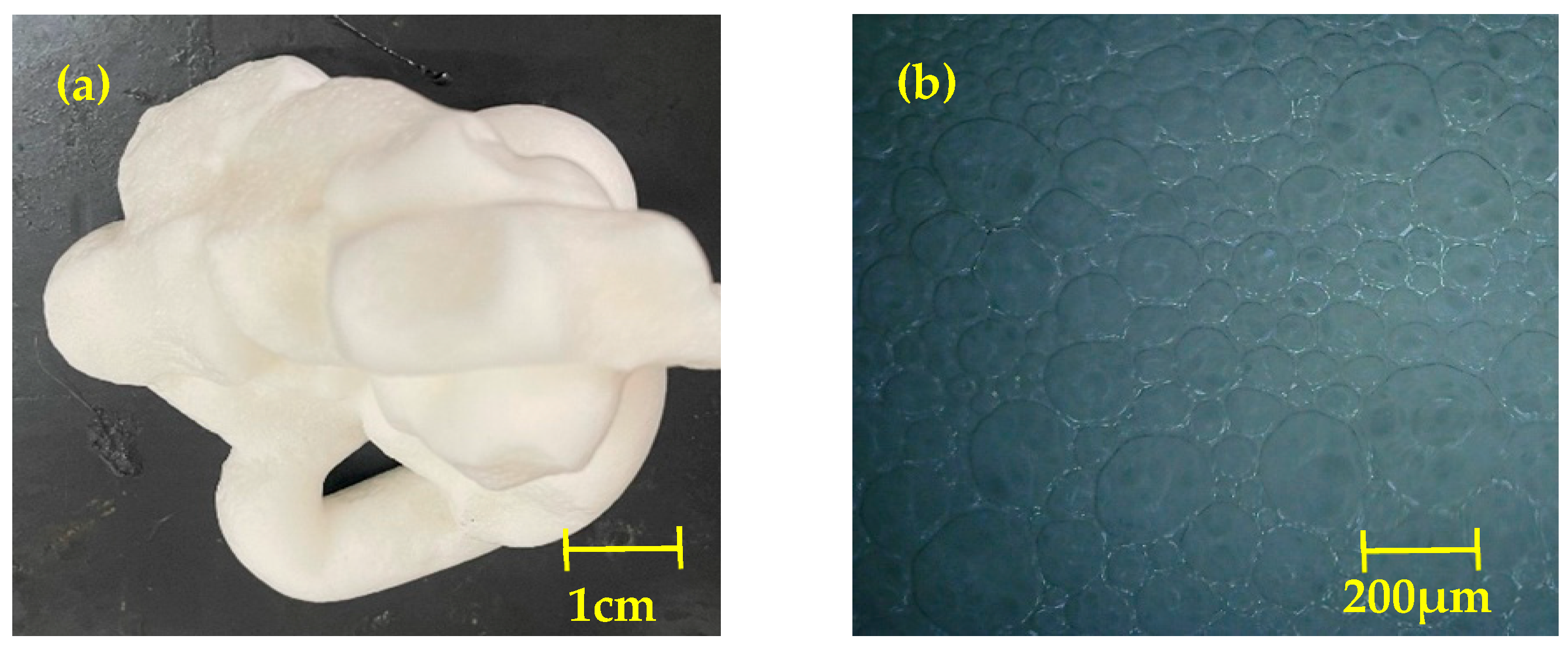
Figure 4.
The preparation process of SSFC.

Figure 5.
Images of the prepared specimens.

Figure 6.
Fluidity of foamed concrete.

Figure 7.
Dry density of foamed concrete.
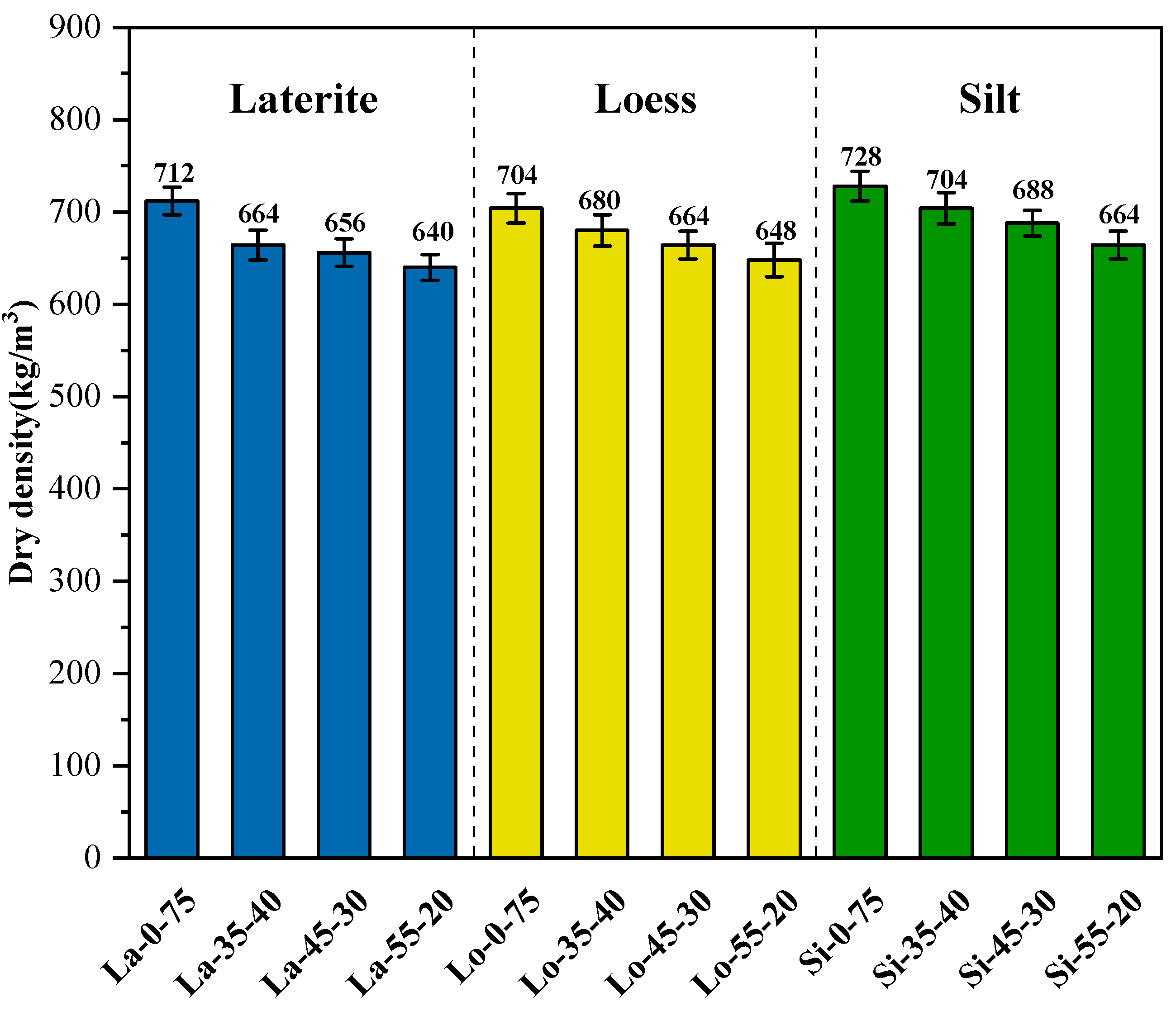
Figure 8.
Compressive strength of foamed concrete with different proportions.
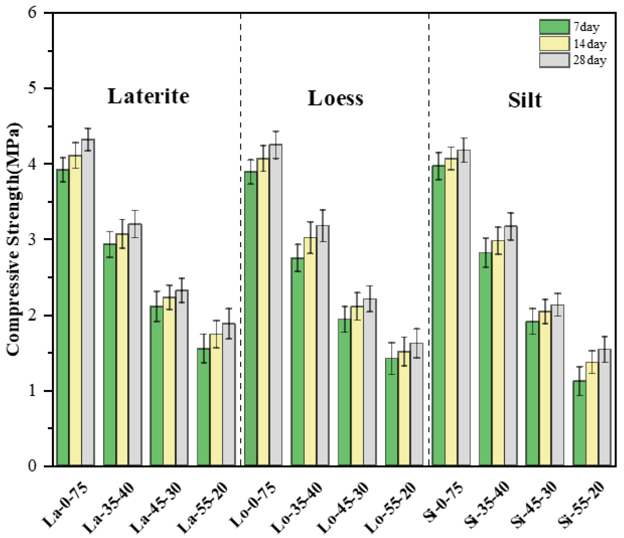
Figure 9.
Water absorption of foamed concrete.

Figure 10.
Drying shrinkage of SSFC prepared with different SS; (a) laterite, (b) loess, (c) silt.
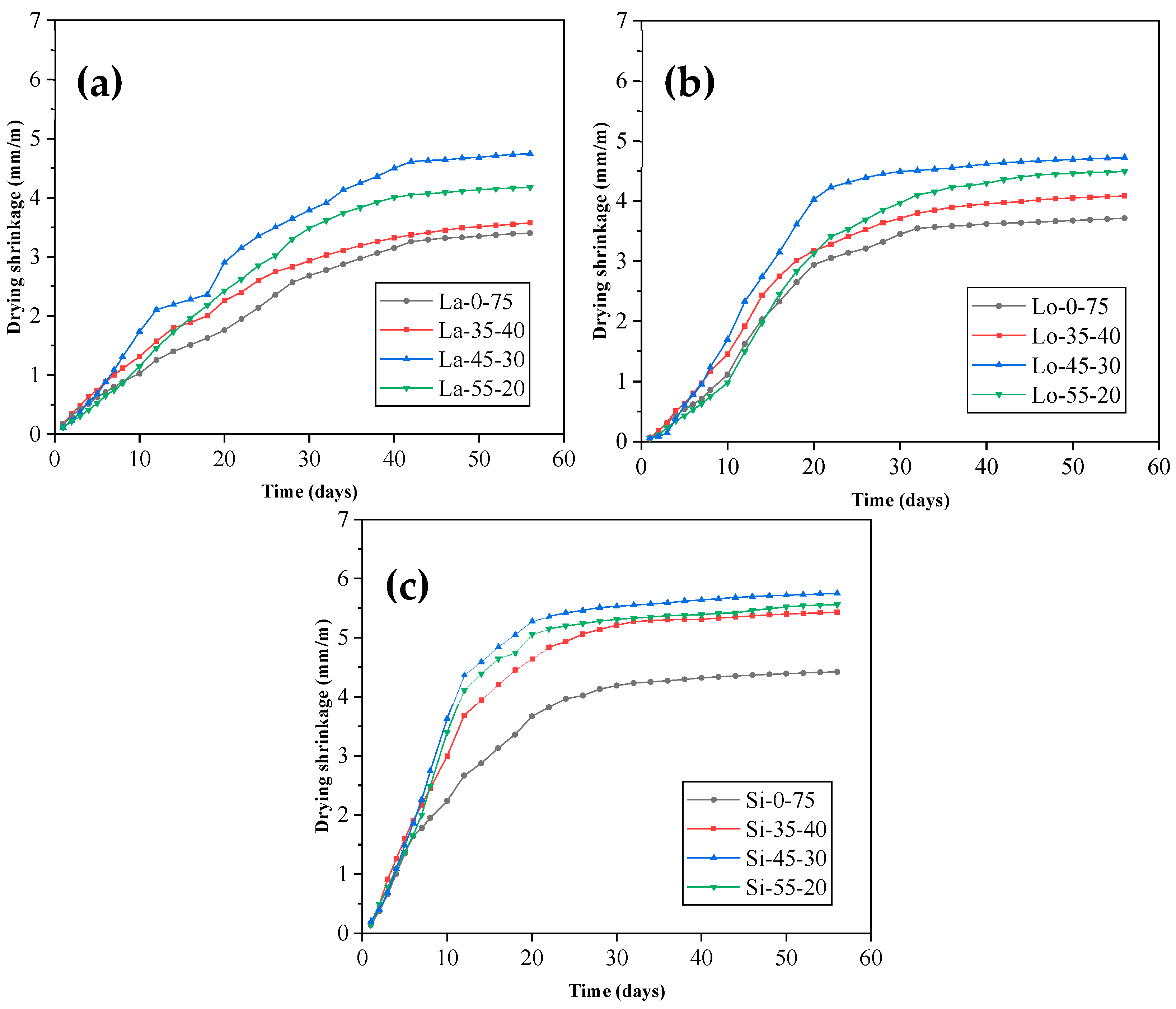
Figure 11.
XRD results of SSFC prepared with different SS; (a) laterite, (b) loess, (c) silt.
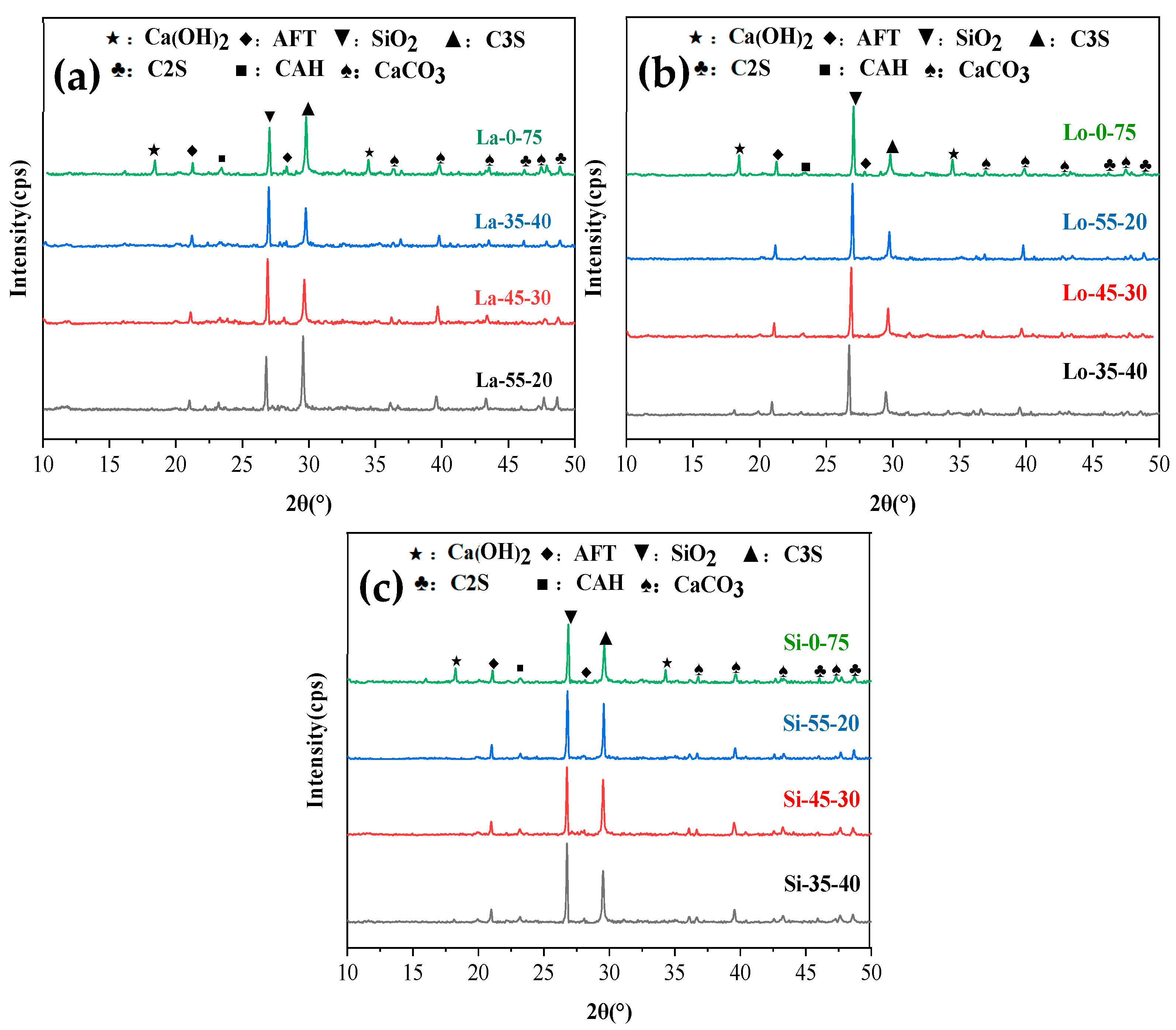
Figure 12.
10,000× SEM images of SSFC; (a) SS particles and CSH, (b) AFT and CSH, (c) CSH and Ca(OH)2.
Figure 12.
10,000× SEM images of SSFC; (a) SS particles and CSH, (b) AFT and CSH, (c) CSH and Ca(OH)2.
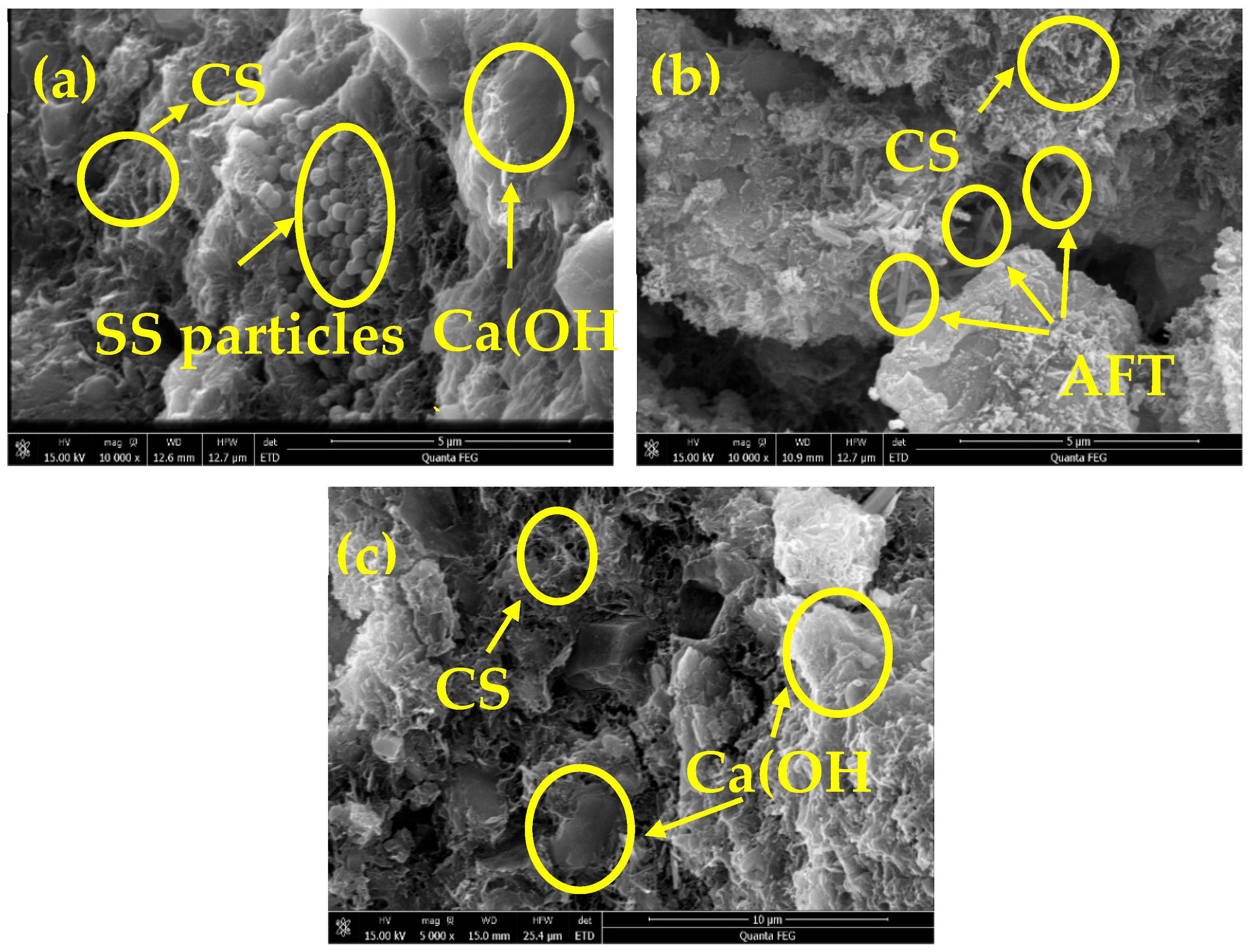
Figure 13.
40× SEM images of SSFC; (a) La-0-75, (b) La-55-20, (c) Lo-0-75, (d) Lo-55-20, (e) Si-0-75, (f) Si-55-20.
Figure 13.
40× SEM images of SSFC; (a) La-0-75, (b) La-55-20, (c) Lo-0-75, (d) Lo-55-20, (e) Si-0-75, (f) Si-55-20.
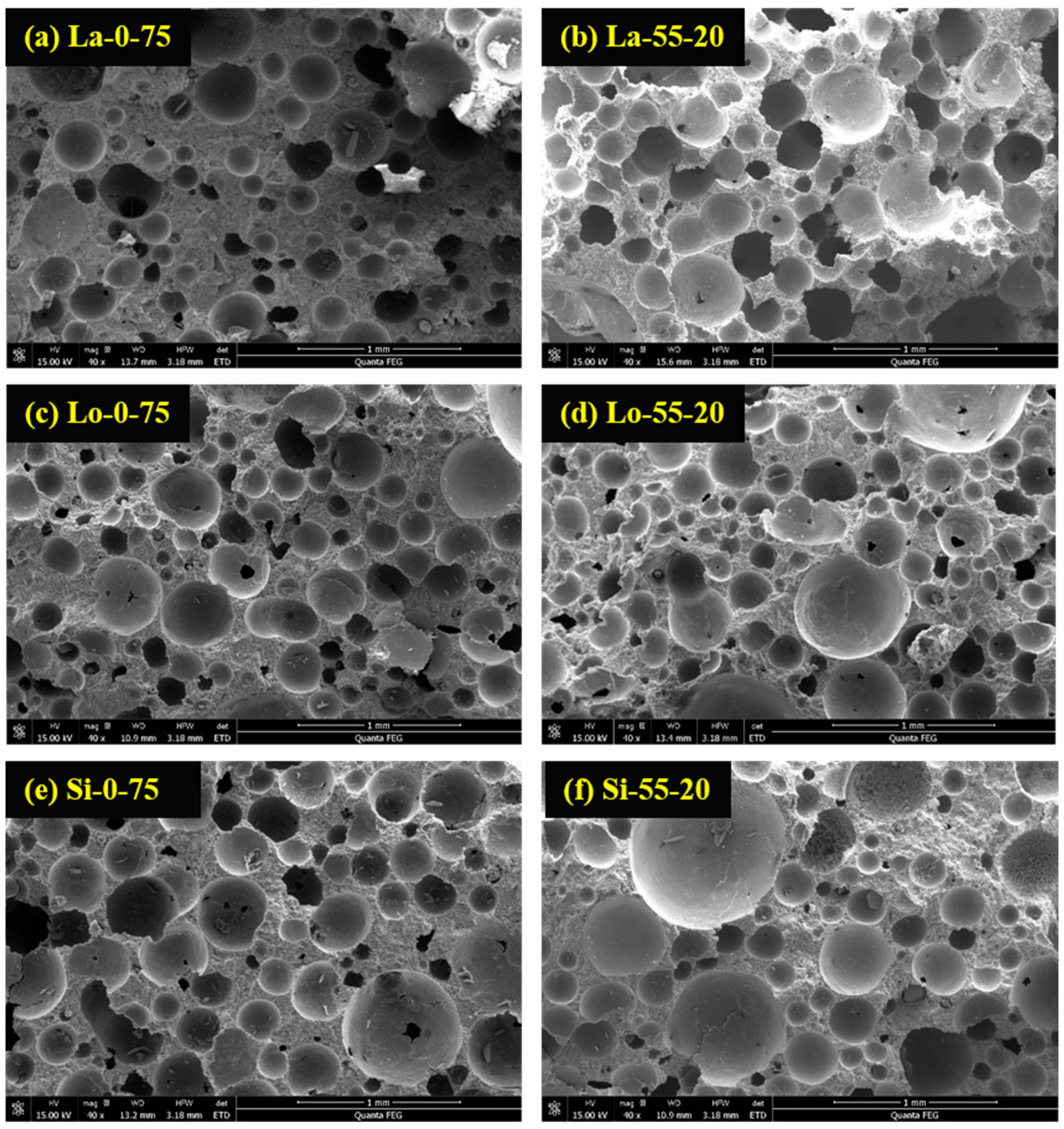
Figure 14.
Pore size distributions of SSFC prepared with different SS; (a) laterite, (b) loess, (c) silt.
Figure 14.
Pore size distributions of SSFC prepared with different SS; (a) laterite, (b) loess, (c) silt.

Figure 15.
Variation of water absorption and 28 d compressive strength with porosity; (a) SSFC prepared with laterite; (b) SSFC prepared with loess; (c) SSFC prepared with silt.
Figure 15.
Variation of water absorption and 28 d compressive strength with porosity; (a) SSFC prepared with laterite; (b) SSFC prepared with loess; (c) SSFC prepared with silt.


Table 1.
Physical properties of cement.
| Physical Properties | Measured Values | |
|---|---|---|
| Specific surface area (kg/m3) | 361 | |
| Normal consistency (%) | 28 | |
| Setting time (min) | Initial set | 223 296 |
| Final set | ||
| 3 days compressive strength (MPa) | 5.6 | |
| 3 days flexural strength (MPa) | 2.74 | |
Table 2.
Chemical compositions of cement, SS, SP.
| Material | SiO2 | Al2O3 | CaO | Fe2O3 | MgO | K2O | TiO2 | Na2O | Mn3O4 |
|---|---|---|---|---|---|---|---|---|---|
| PC | 21.61 | 6.13 | 58.19 | 4.00 | 0.84 | 0.99 | 0.33 | 0.13 | 3.94 |
| Laterite | 60.62 | 12.86 | 7.16 | 4.54 | 1.43 | 2.91 | 0.67 | 1.62 | 0.11 |
| Loess | 69.43 | 13.43 | 1.19 | 5.01 | 1.11 | 2.42 | 0.77 | 0.50 | 0.075 |
| Silt | 67.07 | 14.58 | 0.85 | 5.91 | 1.48 | 2.51 | 0.89 | 1.14 | 0.091 |
| SP | 32.24 | 15.38 | 40.11 | 0.36 | 8.98 | 0.52 | 0.55 | 0.44 | 0.22 |
Table 3.
Constituent proportions of SSFC mixtures.
| Code. | Type of Soil | Design Wet Density (kg/m3) | Soil (kg/m3) | SP (kg/m3) | PC (kg/m3) | Sodium Sulfate (kg/m3) | Water (kg/m3) | Foam (kg/m3) |
|---|---|---|---|---|---|---|---|---|
| La-0-75 | Laterite | 900 | 160 | 0 | 480 | 9.6 | 288 | 30 |
| La-35-40 | 900 | 160 | 224 | 256 | 9.6 | 288 | 25.6 | |
| La-45-30 | 900 | 160 | 288 | 192 | 9.6 | 288 | 24.5 | |
| La-55-20 | 900 | 160 | 352 | 128 | 9.6 | 288 | 23.5 | |
| Lo-0-75 | Loess | 900 | 160 | 0 | 480 | 9.6 | 288 | 30 |
| Lo-35-40 | 900 | 160 | 224 | 256 | 9.6 | 288 | 30 | |
| Lo-45-30 | 900 | 160 | 288 | 192 | 9.6 | 288 | 28.8 | |
| Lo-55-20 | 900 | 160 | 352 | 128 | 9.6 | 288 | 27.7 | |
| Si-0-75 | Silt | 900 | 160 | 0 | 480 | 9.6 | 288 | 30 |
| Si-35-40 | 900 | 160 | 224 | 256 | 9.6 | 288 | 24.5 | |
| Si-45-30 | 900 | 160 | 288 | 192 | 9.6 | 288 | 23.5 | |
| Si-55-20 | 900 | 160 | 352 | 128 | 9.6 | 288 | 22.4 |
Code (Example): La-35-40: Laterite 25%–SP 35%–Cement 40%.
Table 4.
Dry–wet cycling test results of SSFC.
| Code | 28 d Compressive Strength (MPa) | Compressive Strength after 5 Dry–Wet Cycles (MPa) | Water Stability Coefficient |
|---|---|---|---|
| La-0-75 | 4.32 | 3.66 | 0.847 |
| La-35-40 | 3.20 | 2.53 | 0.806 |
| La-45-30 | 2.32 | 1.85 | 0.797 |
| La-55-20 | 1.88 | 1.43 | 0.761 |
| Lo-0-75 | 4.25 | 3.72 | 0.875 |
| Lo-35-40 | 3.18 | 2.64 | 0.830 |
| Lo-45-30 | 2.21 | 1.76 | 0.796 |
| Lo-55-20 | 1.62 | 1.22 | 0.753 |
| Si-0-75 | 4.18 | 3.72 | 0.890 |
| Si-35-40 | 3.17 | 2.75 | 0.868 |
| Si-45-30 | 2.13 | 1.71 | 0.803 |
| Si-55-20 | 1.54 | 1.18 |
Table 5.
Pore structure characterization of SSFC.
| Code | Average Diameter (μm) | Porosity (%) |
|---|---|---|
| La-0-75 | 160.47 | 0.39 |
| La-35-40 | 172.11 | 0.42 |
| La-45-30 | 173.50 | 0.44 |
| La-55-20 | 182.56 | 0.48 |
| Lo-0-75 | 167.39 | 0.41 |
| Lo-35-40 | 169.48 | 0.45 |
| Lo-45-30 | 173.13 | 0.52 |
| Lo-55-20 | 186.22 | 0.54 |
| Si-0-75 | 163.52 | 0.44 |
| Si-35-40 | 168.46 | 0.46 |
| Si-45-30 | 173.62 | 0.49 |
| Si-55-20 | 183.45 | 0.54 |
Publisher’s Note: MDPI stays neutral with regard to jurisdictional claims in published maps and institutional affiliations. |
© 2022 by the authors. Licensee MDPI, Basel, Switzerland. This article is an open access article distributed under the terms and conditions of the Creative Commons Attribution (CC BY) license (https://creativecommons.org/licenses/by/4.0/).
Share and Cite
MDPI and ACS Style
Yang, X.; Xu, S.; Zhao, Z.; Lv, Y. Strength, Durability, and Microstructure of Foamed Concrete Prepared Using Special Soil and Slag. Sustainability 2022, 14, 14952. https://doi.org/10.3390/su142214952
AMA Style
Yang X, Xu S, Zhao Z, Lv Y. Strength, Durability, and Microstructure of Foamed Concrete Prepared Using Special Soil and Slag. Sustainability. 2022; 14(22):14952. https://doi.org/10.3390/su142214952
Chicago/Turabian StyleYang, Xinkui, Shi Xu, Zenggang Zhao, and Yang Lv. 2022. "Strength, Durability, and Microstructure of Foamed Concrete Prepared Using Special Soil and Slag" Sustainability 14, no. 22: 14952. https://doi.org/10.3390/su142214952
Note that from the first issue of 2016, this journal uses article numbers instead of page numbers. See further details here.