
Power Quality Enhancement of Grid-Connected Renewable Systems Using a Matrix-Pencil-Based Active Power Filter

1
College of Engineering and Technology, American University of the Middle East, Kuwait
2
ECE Department, Faculty of Engineering, Beirut Arab University, Beirut 11-5020, Lebanon
3
LaRGES, CRSI, Faculty of Engineering, Lebanese University, Tripoli 1300, Lebanon
*
Author to whom correspondence should be addressed.
Sustainability 2023, 15(1), 887; https://doi.org/10.3390/su15010887
Submission received: 26 November 2022
/
Revised: 19 December 2022
/
Accepted: 28 December 2022
/
Published: 3 January 2023
(This article belongs to the Special Issue Power System Challenges toward Renewable Energies’ Integration)
Abstract
:Power electronic converters are used for integrating renewable energy sources such as wind and photovoltaic into the grid. This integration gives rise to many challenges in power systems, especially regarding power quality. Indeed, integrated systems generate a non-linear current full of harmonics, which degrades power quality. Active power filters are usually used to compensate for these harmonics at the point of common coupling. In the control of active power filters, harmonics need to be extracted from the non-linear current. In this paper, the matrix pencil method―a model-based technique for estimating parameters of exponentially damped or undamped sinusoids in noise―is proposed to extract the reference signal in shunt active power filter applications. The performance of the proposed matrix pencil method is studied for current harmonic compensation and power factor correction under different modulation schemes and two DC links: an external DC voltage source and a capacitor. Using a capacitor for the DC link requires not only including a proportional-plus-integral controller to maintain a constant capacitor voltage, but also accounting for the loss current in the formulation of the matrix pencil method. Compared with the instantaneous reactive power theory and synchronous reference frame, results obtained from simulated data using MATLAB/Simulink under different loading conditions show that the proposed method corrects the power factor and affords a lower source current total harmonic distortion and fast response.
1. Introduction
With recent soaring energy prices and the urgency to act on combating climate change, there is an unprecedented need to transition to environmentally friendly and cost-effective energy solutions. Renewable energy systems generate clean, sustainable energy, and hence can reduce global dependence on fossil fuels and greenhouse gas emissions as well as lower energy costs [1]. Being intermittent, fluctuating, and non-dispatchable, renewable sources such as solar and wind present certain challenges when integrated into the grid, one of which is power quality. Their integration calls for the use of many power electronic converters, which generate voltage and current harmonics, thus polluting the power system and resulting in degraded power quality [2,3,4,5]. Poor power quality can lead to abnormal operating conditions for many electrical and electronic devices and cause huge economic loss in the power network and to the end customers [6]. This is compounded by the fact that growth in the use of power electronic devices―such as variable frequency drives, arc furnaces, variable-speed motor drives, and uninterruptable power supplies―also results in power quality issues [7]. Such non-linear loads generate source voltage and current harmonics, causing interference with communication lines as well as overheating and failure of power-system equipment [8,9,10,11]. In addition to the issues caused by harmonics, a low power factor (PF) can also degrade power quality and compromise system stability, as a low power factor can cause the load current to exceed the rated current and result in higher power generation and line losses [12].
To overcome power quality issues caused by grid-integrated systems, a shunt active power filter (SAPF) can be used to mitigate source current harmonics [13]. An APF extracts non-linear load current harmonics and uses them to construct a reference signal that modulates a voltage source inverter (VSI). As depicted in Figure 1, the compensation current synthesized by the VSI is then injected at the point of common coupling (PCC), resulting in lower source current harmonics.
The accuracy of harmonic current extraction plays an important role in SAPF effectiveness for suppressing the harmonic current and compensating for the power factor. The instantaneous reactive power theory (IRPT) [14] and synchronous reference frame (SRF) [15] are considered the most used time-domain-based methods for reference signal extraction in SAPF [16,17]. Both methods rely on a low-pass filter in their implementation to extract a DC component that represents the fundamental frequency. This filter is known to cause large amplitude and phase errors, leading to inaccuracies in the extracted reference signal [18]. In [19], the low-pass filter was replaced with an average power detector, since in the rotating frame the DC element of a signal is equal to its average value. The authors of [20] dispensed with the filter by integrating the matrix pencil method (MPM)―a model-based parameter estimation algorithm―into the SRF to extract the DC component in the dq frame. In [21], the matrix pencil method (MPM) was proposed for reference signal extraction in the abc frame. In contrast to [20], Ref. [21] completely replaced SRF, and not only the filter, with MPM. This was achieved by using MPM to decompose the total load current in the abc into its constituent frequency components before synthesizing the fundamental pure sine wave and subtracting it from the load current to obtain the reference signal. MPM was shown to achieve better performance regarding source current total harmonic distortion (THD) and response time than the IRPT and SRF. However, Ref. [21] neither corrected the power factor nor explained how the output of the DC link proportional-plus-integral controller could be integrated into the formulation of MPM. Moreover, it studied the performance of MPM using only the pulse width modulation (PWM).
This paper complements the previously published results in [21] by studying the performance of MPM for current harmonic compensation and power factor correction under different modulation schemes and two DC links: an external DC voltage source and a capacitor. Using a capacitor for the DC link requires not only including a PI controller to maintain a constant capacitor voltage, but also accounting for the loss current in the formulation of MPM.
The remainder of this paper is organized as follows: Section 2 outlines the structure of the SAPF used for the simulation. Section 3 describes the functionality of the DC link. Section 4 recalls the mathematical approach of MPM and explains the integration of the DC link with the reference signal extraction. In Section 5, different simulations are discussed and the performance of MPM is evaluated. Finally, Section 6 concludes this work.
2. Structure of SAPF
The active power filter has many topologies, such as shunt, series, and unified power quality conditioner (UPQC)―which is the combination of shunt and series [22,23]. As shown in Figure 2, the SAPF structure consists of a VSI, a modulation process, and a reference signal extraction process. The integrated system generating the non-linear current is represented by a non-linear load. The load current is measured by sensors and fed to the extraction process, where the harmonics are extracted; then, this reference signal is used in the modulation module to suppress the harmonics from the source current. The modulation module is responsible for injecting the harmonic current at the PCC by means of power electronic switches such as IGBTs, MOSFETs, and GTOs. This will enable the DC-link voltage to inject mitigation current into the power circuit for harmonic suppression. The most used modulation techniques are PWM, hysteresis control, and SVPWM. The reference signal extraction, modulation process, and DC link control are the fields under research in the SAPF considered to achieve an enhanced performance with lower %THD and fast response that can form a more efficient and reliable filter [24].
The SAPF power circuit consists of a three-phase AC voltage source including source impedance and a line impedance connected to a non-linear RL load. The SAPF is connected at PCC via a filter inductance , which is considered the coupling reactance of the SAPF. The VSI DC link generally consists of an external battery or a capacitor , as shown in Figure 3.
The SAPF works by extracting the reference signal with a proper DC link control outer loop, modulating this reference signal, and then injecting the harmonic current at PCC. This operation enables compensating source harmonic current but draws a small amount of source current to regulate switching losses when using a capacitor in the DC link [25]. This capacitor has the role of maintaining a DC with few ripples in the steady state and operating as an energy storage component to deliver the power gap between the supply source and load in the transient state [11]. A three-phase three-wire SAPF is considered in this study.
3. The DC Link
The DC link provides the necessary power for the injected harmonic signal. It can be achieved by using a constant external DC voltage source, such as a battery; or by using a DC-link capacitor with a proper control strategy to maintain its voltage at a specific desired value. In this study, both cases will be tested to compare the performance of MPM against IRPT and SRF.
The DC-link capacitor behaves as an energy-storage element with a constant voltage value for the VSI, which functions as a current-mode power converter voltage source to generate the mitigation current injected into the power circuit. During the steady state, the source power must be the same as the load-demand real power without real power consumed by the VSI for a lossless system. By that, the DC-link capacitor average voltage must be maintained at a desired constant value. To control the DC link at the desired reference voltage, conventional methods, such as proportional-plus-integral (PI) controller and fuzzy logic control (FLC) [25], are widely used for this purpose, which applies the voltage difference between the DC-link voltage and the reference voltage to its control strategy. Other methods were proposed for the DC-link voltage regulation control as in [26,27]. Also, the authors in [28] dealt with energy equations for the control of DC-link voltage with step-size error for proper regulation.
Based on IRPT and SRF theory, the current component in the d-axis represents the total input of instantaneous active power in the grid synchronous rotating frame. By that, the DC link PI controller output average voltage determines one of the d-axis current references. Accordingly, if the DC link average voltage is higher than the reference voltage, positive power will let a flow of energy from the inverter to the grid; and if the DC link average voltage is lower than the reference, the negative power will let a flow of energy from the grid to the inverter [29].
Figure 4 represents the adopted DC link control strategy using a PI controller, where the Vref represents the DC voltage reference value and Vdc represents the capacitor instantaneous voltage value. The difference between these two values represents the error, which serves as the input to the PI controller. The active power exchange between the grid and the DC link is caused by current Iloss, which reflects the fundamental frequency of the active current. The transfer function of this outer loop PI controller is presented in [30].
The DC-link capacitance has an impact on the DC voltage variations in the transient and steady states. The DC voltage must secure a safe operating range, with a minimum reference value greater than the grid peak line voltage [31]. However, when the voltage is too high, high current harmonics may damage the inverter’s power electronics devices, especially switches; and when the voltage is too low, a switch’s freewheel diodes may not be reverse-biased, to help the SAPF control current. The voltage variation of the capacitor’s DC link is directly proportional to the integral of capacitor current and inversely proportional to the capacitance value; hence the minimum value of capacitance can be defined according to the equation:
where denotes the capacitor current and represents the maximum variation of the DC voltage over the response period from 0 to . Several papers expressed different selection criteria for the DC-link capacitor size and coupling inductance value. These approaches are discussed and compared in [32]. In case two, capacitors are used in the DC link; a model predictive control strategy for voltage balance of the DC side can be used as proposed in [33].
4. Integrating the loss current in MPM formulation
In this section, the mathematical formulation of MPM is recalled, and the integration of the DC link PI controller output into this formulation is presented.
4.1. Signal Model
With the aid of Euler’s formula, it is possible to model the current flowing through a non-linear load for a sinusoidal voltage source as a sum of n complex-valued sinusoidal signals weighted by complex residues using the exponential signal model as follows [34]:
where is the complex residue of the cisoid and is its frequency. After sampling, the time variable, , is replaced by , where is the sampling period and is the sample index. The discrete current signal becomes:
where is the complex pole and N is the number of samples. In matrix form, the signal model is formulated by:
where
The superscript represents the transpose operator.
Having the load current data sequence , the complex residues and the frequencies are estimated. The fundamental component of the non-linear load current, which is a pure sine wave, is constructed using the fundamental frequency estimated parameters. This sine wave is subtracted from the load current to generate the harmonics reference signal that needs to be injected at PCC to mitigate the source current harmonics.
4.2. The Matrix Pencil Method
In this section, the steps of the matrix pencil method are outlined. MPM utilizes the structure of the matrix pencil of the underlying signals for model parameter estimation. It has been effectively applied to frequency-dependent multi-path resolving [35], extraction of wave objects from scattering data [36], direction-of-arrival estimation [37], and parameter estimation in dispersive media [38,39,40]. In this study, the frequencies and amplitudes estimated by MPM from the non-linear load current will be used to construct the harmonic reference signal of the SAPF that needs to be injected at PCC for harmonic compensation of the source current.
The reference signal could be obtained by MPM by applying the following steps:
First, using the current data sequence , a Hankel data matrix is constructed:
where is the selected pencil parameter that
Then, and are formed and used to form a matrix pencil defined as , with a scalar parameter. In the case of a noiseless exponential data model,
and admit the following Vandermonde decomposition [40]:
and
where
The decomposition of Vandermonde shows the shift-invariance property along the column and row spaces, and results in writing the matrix pencil:
Finally, the complex poles are estimated as the generalized eigenvalues of the matrix pair . The frequencies can then be estimated from the poles, and then the amplitudes are estimated using a least-squares fit having the following solution: where the superscript denotes the conjugate-transpose operator.
After the construction of the load current fundamental component, the harmonics are determined by subtracting the constructed fundamental current from the load current. The obtained harmonics represent the reference signal that needs to be sent to the modulation module. However, when a capacitor is used in the DC link instead of an external DC voltage source, the voltage value of the capacitor must be maintained at the desired reference. There is a small amount of active real power used by SAPF due to VSI switching losses. These losses caused by the PI outer loop controller must be added to MPM constructed fundamental component in the abc frame. To this end, this value is transferred from the dq frame to the abc frame to be added to the fundamental current; and the resultant value needs to be subtracted from the load current to generate the harmonics reference signal. This extracted reference signal is then sent to the modulation module, which is responsible for the functionality of the VSI switches to form the injected current.
The role of MPM in active power filters is illustrated in the block diagram of Figure 5. In the first step, MPM decomposes the measured load current into its constituent frequency components, according to Equation (2). The second step synthesizes the fundamental component using the fundamental frequency and its complex residue. The third step adds the losses from the DC link control circuit to the fundamental component. Finally, the resulting reference signal is subtracted from the load current to obtain the harmonic reference signal used in the active power filter.
5. Simulation Results and Discussion
In this section, MPM is tested and compared to IRPT and SRF. The models in Figure 2 and Figure 3 are simulated using MATLAB/Simulink, first with the DC link as a battery, and then as a capacitor with a proper outer loop PI controller. In both cases, hysteresis, PWM, and SVPWM modulation processes are used to check the performance of MPM, IRPT, and SRF. The comparison is based on the value of the source current %THD and the response time, which is defined as the time needed for the capacitor to reach its reference voltage. For the capacitor DC link, three different loads are used: a non-linear load 1 for static response check, a non-linear load 2 parallel to load 1 to check the SAPF dynamic response, and a highly inductive load 3 parallel to load 1 to check the power factor compensation capability of the proposed method. All simulations are performed in discrete time with a time step of 1 × 10⁻⁶ s. For the PWM and SVPWM, the switching frequency is set to 12.5 kHz, while for the hysteresis control, the hysteresis band is set to 0.1 A. The circuit parameters used in the simulation scenarios are given in Table 1.
Figure 6 shows the MATLAB Simulink model of the SAPF. All the equations in Section 4 are written as MATLAB function block in the MPM subsystem, where the input is the load current and source voltage measurement, and the output is the harmonics reference signal. The remaining components of the model are the power circuit, the DC link control, and the modulation control.
5.1. Battery DC Link
In this scenario, nonlinear load 1 is used along with an external 700-V battery in the DC link instead of a capacitor. As shown in Figure 7, the FFT analysis of the source current without the SAPF gives a THD of 25.61%.
To reduce these harmonic distortions, first the reference signal is extracted by IRPT, SRF, and MPM, and then the resulting compensated current synthesized by the SAPF is injected at the PCC. For each extraction approach, three modulation schemes are considered: hysteresis control, PWM control, and SVPWM control. The obtained %THD results of the source current are summarized in Table 2.
The results in Table 2 reveal that MPM achieves a lower THD than IRPT and SRF for all modulation approaches. Figure 8 shows the FFT analysis of the source current resulting from the three extraction methods and PWM control. These results confirm the better compensation of MPM across all harmonic orders.
It is worth noting that while the %THD of the source current in Table 2 is for all harmonic orders under different extraction and modulation techniques, Figure 8 gives more insight into how the percentage in Table 2 is distributed among the harmonic orders under different extraction techniques and PWM control.
Figure 9 depicts the steady-state waveforms of the load current IL, the compensation current Ih, and the source current Is, using the three extraction methods and PWM control. The results reveal the effectiveness of MPM in compensating source current harmonics to obtain a nearly sinusoidal source current. Figure 9c, depicting the waveform when using MPM, reveals a smoother source current waveform than that of the IRPT and SRF, which agrees with the results in Table 2.
5.2. Capacitor DC Link
In this simulation scenario, a capacitor Cdc is used in the DC link with the value given in Table 1. A PI controller is used for the outer control loop to set the capacitor voltage at a specified reference value. IRPT, SRF, and MPM are tested using hysteresis, PWM, and SVPWM to check the performance of these extraction methods in mitigating the source current harmonics. The source current THDs are summarized in Table 3.
MPM lowers the 25.6% THD of the source current to 1.21%, 0.85%, and 0.93% when using hysteresis control, PWM control, and SVPWM control, respectively. On the other hand, IRPT reduces the source current to 1.74%, 1.21%, and 1.37%, while SRF reduced the THD to 1.61%, 1.43%, and 1.54% using hysteresis control, PWM control, and SVPWM control. The results confirm the effectiveness of MPM over IRPT and SRF with various modulation controls. The FFT analyzer using SVPWM control for the IRPT, SRF, and MPM is shown in Figure 10, where MPM successfully compensates the source current harmonics.
The steady-state waveforms of the SAPF when using SVPWM control with IRPT, SRF, and MPM are shown in Figure 11. The results again demonstrate the effectiveness of MPM in restoring a nearly sinusoidal source current.
The response time of the SAPF can be defined as the time it takes the DC-link capacitor to reach its reference value. Figure 12 shows that the system considered required approximately 0.8 s to attain its steady state when using IRPT and 0.2 s when implementing SRF. Using MPM also resulted in a response time of approximately 0.2 s, which was faster than the IRPT and very close to that of SRF. This confirms a fast response of MPM in eliminating the source current harmonics in SAPF applications.
5.3. Dynamic Response under Capacitor DC Link
This simulation scenario examines MPM’s dynamic response to load changes, where a transient state is introduced by adding a non-linear load 2 (RL = 20 Ω, LL = 1 mH) in parallel to non-linear load 1. The waveform of the source current and its FFT analyzer with no filter for this load condition are depicted in Figure 13 with a THD of 23.22%.
To evaluate the performance of the SAPF, load 2 is added to load 1 at t = 0.4 s with capacitor voltage initially set to 700 V. The FFT analyzer of the source current with hysteresis control using the IRPT, SRF, and MPM at the new load condition is shown in Figure 14. The results reveal the higher performance of MPM compared to IRPT and SRF under the new load conditions by reducing the source current from 23.22% to 0.64% in a hysteresis control; whereas the IRPT and SRF reduce the source current from 23.22% to 1.04% and 1.51%, respectively, using the same modulation control. The other modulation control results are summarized in Table 4.
The transient response of the SAPF in mitigating the source current harmonics under load change for the different extraction techniques using hysteresis control is shown in Figure 15. The results confirm the ability of MPM to compensate for the source current harmonics under a transient condition of load change.
5.4. Power Factor Correction under Capacitor DC Link
In this simulation scenario, MPM is evaluated under a highly inductive load condition to test its ability to correct the power factor. For this purpose, a highly inductive linear load 3 with (RL = 5 Ω, LL = 20 mH) is added in parallel to the non-linear load 1. The waveform of the source current and its FFT analyzer with no filter are reflected in Figure 16 with a THD of 7.47%. This value is lower than that of load 1 and load 2 with no filter due to its highly inductive property. The power factor of load 1 with no filter is 0.9961, whereas the PF when load 3 is added to load 1 is 0.8147.
Before checking the PF correction property of MPM, the harmonic reduction performance when adding load 3 must be assessed. For that, Figure 17 presents the FFT analyzer of the SAPF with a PWM modulation when using the IRPT, SRF, and MPM. It is clear from the results that MPM gives a better performance, reducing the source current harmonics from 7.47% to 0.55%, as well as achieving a lower THD than IRPT (0.86%) and SRF (0.89%).
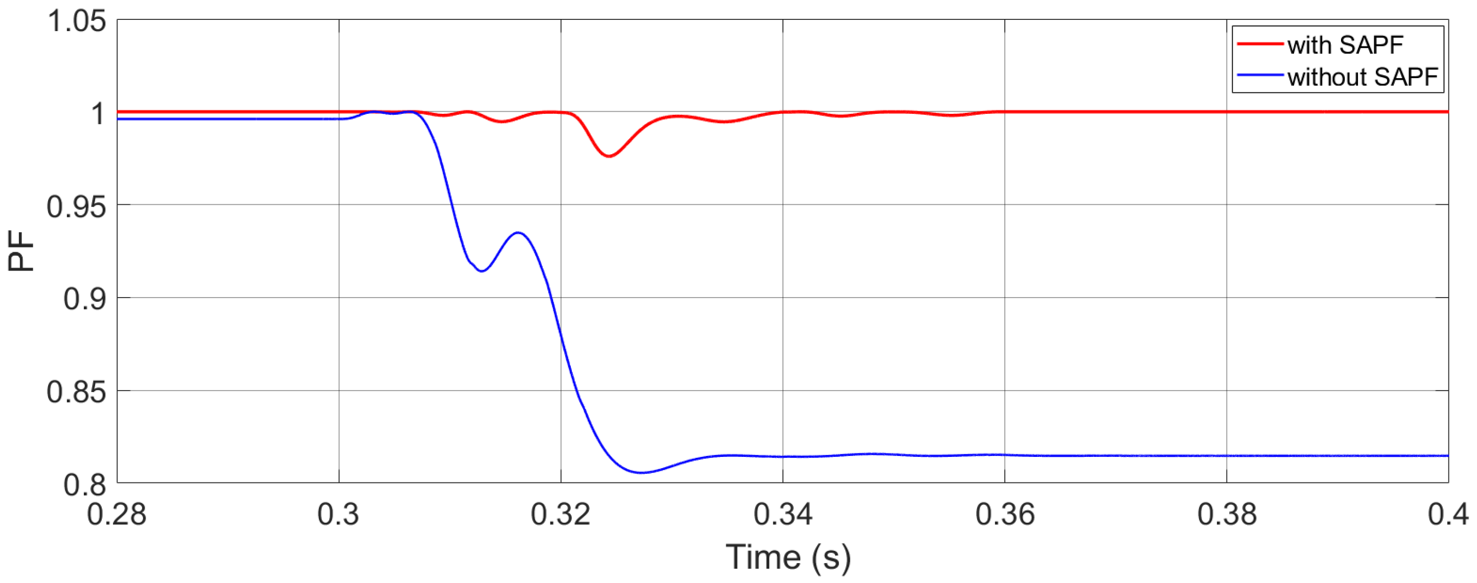
Both IRPT and SRF can compensate for the reactive power to reach a unity power factor by using a low pass filter in their implementation. Although MPM does not use a filter, it can correct the power factor by shifting the compensated current at PCC. This is achieved by first calculating the required phase shift from the measured load power factor and then using it to shift the reference signal generated by MPM. To illustrate this property, Figure 18 shows two PF curves function of time. The blue curve is the power factor without SAPF. It starts at 0.9961 when only load 1 is present, and then drops to 0.8147 when load 3 is inserted at t = 0.3 s in parallel to load 1. The red curve is the PF but with SAPF using MPM and PWM modulation. It can be seen that the PF is initially corrected to unity for load 1 and then undergoes a fast transient to reach unity again after the insertion of load 3 at t = 0.3 s. This reveals the ability of MPM to compensate for reactive power.
In summary, the results obtained in all simulation scenarios reveal the superior performance of the shunt active filter when using MPM as an extraction technique rather than IRPT and SRF. Indeed, MPM renders lower source current THD under different modulation processes and different DC link sources, thus enhancing the power quality of grid-connected renewable systems. Using the same hardware processor, IRPT or SRF algorithm can be straightforwardly replaced by the proposed MPM at no additional cost or hardware circuit requirements. MPM has the potential to improve power system quality and minimize the economic losses of both the power network operator and consumer.
6. Conclusions
Integrating renewable energy sources into the grid requires the use of power electronic converters, which cause harmonics and degrade power quality, leading to economic loss for both the network operator and the consumer. An APF can be used to compensate for the source current and voltage harmonics. Reference signal extraction is considered the first and main control module in the SAPF. In this paper, MPM was proposed for reference signal extraction; and its performance was compared to IRPT and SRF in terms of THD, dynamic response, and power factor correction. The comparison was carried out under three modulation schemes: PWM, hysteresis, and SVPWM; and two DC links: a battery and a capacitor. For the capacitor, it was shown how the loss current can be integrated into the formulation of MPM for reference signal extraction. For both DC links and all modulation schemes, MPM resulted in a lower source current THD compared with IRPT and SRF, when tested for one load. When evaluated for two loads under capacitor DC link and hysteresis, MPM again afforded a lower source current THD and showed a fast dynamic response. Finally, testing MPM for power factor correction under capacitor DC link and PWM modulation showed that MPM could achieve a unity power factor like the other two methods, albeit at a lower source current THD. These results attest to the power quality improvements of MPM for reference signal extraction in active power filter applications. For future work, MPM can be modified to dispense with the phase locked loop needed when adding the losses in the dq frame into the abc frame fundamental element. This has the advantage of isolating the extraction technique from any source disturbances and further enhancing the performance of the SAPF.
Author Contributions
Conceptualization, A.E.G. and K.C.; methodology, A.E.G. and K.C.; software, A.E.G. and K.C.; validation, A.E.G., N.M., K.C., and M.T.; formal analysis, A.E.G.; resources, M.T. and N.M.; data curation, A.E.G. and K.C.; writing—original draft preparation, A.E.G. and K.C.; writing—review and editing, M.T. and N.M.; visualization, A.E.G.; supervision, K.C., M.T., and N.M. All authors have read and agreed to the published version of the manuscript.
Funding
This research received no external funding.
Institutional Review Board Statement
Not applicable.
Informed Consent Statement
Not applicable.
Data Availability Statement
Not applicable.
Conflicts of Interest
The authors declare no conflict of interest.
References
- Jayaram, J.; Srinivasan, M.; Prabaharan, N.; Senjyu, T. Design of Decentralized Hybrid Microgrid Integrating Multiple Renewable Energy Sources with Power Quality Improvement. Sustainability 2022, 14, 7777. [Google Scholar] [CrossRef]
- Munir, H.; Zou, J.; Xie, C.; Guerrero, J. Cooperation of Voltage Controlled Active Power Filter with Grid-Connected DGs in Microgrid. Sustainability 2018, 11, 154. [Google Scholar] [CrossRef] [Green Version]
- Boukezata, B.; Chaoui, A.; Gaubert, J.-P.; Hachemi, M. Power Quality Improvement by an Active Power Filter in Grid-Connected Photovoltaic Systems with Optimized Direct Power Control Strategy. Electr. Power Compon. Syst. 2016, 44, 2036–2047. [Google Scholar] [CrossRef]
- Kumar, R.; Bansal, H.O. Shunt Active Power Filter: Current Status of Control Techniques and Its Integration to Renewable Energy Sources. Sustain. Cities Soc. 2018, 42, 574–592. [Google Scholar] [CrossRef]
- Rao, S.N.V.B.; Kumar, Y.V.P.; Pradeep, D.J.; Reddy, C.P.; Flah, A.; Kraiem, H.; Al-Asad, J.F. Power Quality Improvement in Renewable-Energy-Based Microgrid Clusters Using Fuzzy Space Vector PWM Controlled Inverter. Sustainability 2022, 14, 4663. [Google Scholar] [CrossRef]
- Sharma, A.; Rajpurohit, B.S.; Singh, S.N. A Review on Economics of Power Quality: Impact, Assessment and Mitigation. Renew. Sustain. Energy Rev. 2018, 88, 363–372. [Google Scholar] [CrossRef]
- Afonso, J.L.; Tanta, M.; Pinto, J.G.O.; Monteiro, L.F.C.; Machado, L.; Sousa, T.J.C.; Monteiro, V. A Review on Power Electronics Technologies for Power Quality Improvement. Energies 2021, 14, 8585. [Google Scholar] [CrossRef]
- Puhan, P.S.; Ray, P.K.; Pottapinjara, S. Performance Analysis of Shunt Active Filter for Harmonic Compensation under Various Non-Linear Loads. Int. J. Emerg. Electr. Power Syst. 2021, 22, 21–29. [Google Scholar] [CrossRef]
- Marian, P.K. Modeling and Control of Power Electronics Converter System for Power Quality Improvements; Elsevier: Amsterdam, The Netherlands, 2018; pp. 31–84. ISBN 9780128145685. [Google Scholar]
- Kashif, M.; Hossain, M.J.; Fernandez, E.; Taghizadeh, S.; Sharma, V.; Ali, S.M.N.; Irshad, U.B. A Fast Time-Domain Current Harmonic Extraction Algorithm for Power Quality Improvement Using Three-Phase Active Power Filter. IEEE Access 2020, 8, 103539–103549. [Google Scholar] [CrossRef]
- Das, S.R.; Ray, P.K.; Sahoo, A.K.; Ramasubbareddy, S.; Babu, T.S.; Kumar, N.M.; Elavarasan, R.M.; Mihet-Popa, L. A Comprehensive Survey on Different Control Strategies and Applications of Active Power Filters for Power Quality Improvement. Energies 2021, 14, 4589. [Google Scholar] [CrossRef]
- Kumar, R.S.; Christopher Raj, I.G.; Saravanan, S.; Leninpugalhanthi, P.; Pandiyan, P. Impact of Power Quality Issues in Residential Systems. In Power Quality in Modern Power Systems; Elsevier: Amsterdam, The Netherlands, 2021; pp. 163–191. ISBN 9780128233467. [Google Scholar]
- Tareen, W.U.; Mekhilef, S.; Seyedmahmoudian, M.; Horan, B. Active Power Filter (APF) for Mitigation of Power Quality Issues in Grid Integration of Wind and Photovoltaic Energy Conversion System. Renew. Sustain. Energy Rev. 2017, 70, 635–655. [Google Scholar] [CrossRef]
- Imam, A.A.; Sreerama Kumar, R.; Al-Turki, Y.A. Modeling and Simulation of a PI Controlled Shunt Active Power Filter for Power Quality Enhancement Based on P-Q Theory. Electronics 2020, 9, 637. [Google Scholar] [CrossRef]
- Tham, Z.Y.; Hoon, Y.; Mohd Radzi, M.A. Synchronous Reference Frame with Finite Impulse Response Filter for Operation of Single-Phase Shunt Active Power Filter. MATEC Web Conf. 2021, 335, 02004. [Google Scholar] [CrossRef]
- Qazi, S.H.; Mustafa, M.W.B.; Soomro, S.; Larik, R.M. Comparison of Reference Signal Extraction Methods for Active Power Filter to Mitigate Load Harmonics from Wind Turbine Generator. In Proceedings of the 2015 IEEE Conference on Energy Conversion (CENCON), Johor Bahru, Malaysia, 19–20 October 2015; pp. 463–468. [Google Scholar]
- Büyük, M.; İnci, M.; Tan, A.; Tümay, M. Improved Instantaneous Power Theory Based Current Harmonic Extraction for Unbalanced Electrical Grid Conditions. Electr. Power Syst. Res. 2019, 177, 106014. [Google Scholar] [CrossRef]
- Chen, D.; Xiao, L.; Yan, W.; Li, Y.; Guo, Y. A Harmonics Detection Method Based on Triangle Orthogonal Principle for Shunt Active Power Filter. Energy Rep. 2021, 7, 98–104. [Google Scholar] [CrossRef]
- Hoon, Y.; Mohd Radzi, M.; Hassan, M.; Mailah, N. A Dual-Function Instantaneous Power Theory for Operation of Three-Level Neutral-Point-Clamped Inverter-Based Shunt Active Power Filter. Energies 2018, 11, 1592. [Google Scholar] [CrossRef] [Green Version]
- Terriche, Y.; Golestan, S.; Guerrero, J.M.; Kerdoune, D.; Vasquez, J.C. Matrix Pencil Method-based Reference Current Generation for Shunt Active Power Filters. IET Power Electron. 2018, 11, 772–780. [Google Scholar] [CrossRef] [Green Version]
- El Ghaly, A.; Tarnini, M.; Moubayed, N.; Chahine, K. A Filter-Less Time-Domain Method for Reference Signal Extraction in Shunt Active Power Filters. Energies 2022, 15, 5568. [Google Scholar] [CrossRef]
- Thentral, T.M.T.; Palanisamy, R.; Usha, S.; Vishnuram, P.; Bajaj, M.; Sharma, N.K.; Khan, B.; Kamel, S. The Improved Unified Power Quality Conditioner with the Modular Multilevel Converter for Power Quality Improvement. Int. Trans. Electr. Energy Syst. 2022, 2022, 1–15. [Google Scholar] [CrossRef]
- Srilakshmi, K.; Sujatha, C.N.; Balachandran, P.K.; Mihet-Popa, L.; Kumar, N.U. Optimal Design of an Artificial Intelligence Controller for Solar-Battery Integrated UPQC in Three Phase Distribution Networks. Sustainability 2022, 14, 13992. [Google Scholar] [CrossRef]
- Huang, C.; Liu, Y.; Song, W.; Liu, K. Designing and Simulation of a Novel Active Power Filter Based on FXLMS Method. In Proceedings of the 2017 IEEE Electrical Design of Advanced Packaging and Systems Symposium (EDAPS), Haining, China, 14–16 December 2017; pp. 1–3. [Google Scholar]
- Musa, S.; Radzi, M.; Hizam, H.; Wahab, N.; Hoon, Y.; Zainuri, M. Modified Synchronous Reference Frame Based Shunt Active Power Filter with Fuzzy Logic Control Pulse Width Modulation Inverter. Energies 2017, 10, 758. [Google Scholar] [CrossRef] [Green Version]
- Hoon, Y.; Mohd Radzi, M.; Hassan, M.; Mailah, N. DC-Link Capacitor Voltage Regulation for Three-Phase Three-Level Inverter-Based Shunt Active Power Filter with Inverted Error Deviation Control. Energies 2016, 9, 533. [Google Scholar] [CrossRef] [Green Version]
- Wang, Y.; Wang, Y.; Chen, S.-Z.; Zhang, G.; Zhang, Y. A Simplified Minimum DC-Link Voltage Control Strategy for Shunt Active Power Filters. Energies 2018, 11, 2407. [Google Scholar] [CrossRef] [Green Version]
- Zainuri, M.A.A.M.; Radzi, M.A.M.; Soh, A.C.; Mariun, N.; Rahim, N.A. DC-link Capacitor Voltage Control for Single-phase Shunt Active Power Filter with Step Size Error Cancellation in Self-charging Algorithm. IET Power Electron. 2016, 9, 323–335. [Google Scholar] [CrossRef]
- Dian, R.; Xu, W.; Mu, C. Improved Negative Sequence Current Detection and Control Strategy for H-Bridge Three-Level Active Power Filter. IEEE Trans. Appl. Supercond. 2016, 26, 1–5. [Google Scholar] [CrossRef]
- Cao, X.; Zhou, S.; Li, J.; Zhang, S. A DC Voltage Control Strategy for Active Power Filter. TOEEJ 2016, 10, 166–180. [Google Scholar] [CrossRef] [Green Version]
- Chen, M.-H. Development of Shunt-Type Three-Phase Active Power Filter with Novel Adaptive Control for Wind Generators. Sci. World J. 2015, 2015, 1–10. [Google Scholar] [CrossRef] [Green Version]
- Rameshkumar, K.; Indragandhi, V. Overview of Reference Current Extraction Techniques in Single Phase Shunt. Int. J. Emerg. Technol. 2020, 26, 689–698. [Google Scholar]
- Li, H.; Liu, Y.; Yang, J. A Novel FCS-MPC Method of Multi-Level APF Is Proposed to Improve the Power Quality in Renewable Energy Generation Connected to the Grid. Sustainability 2021, 13, 4094. [Google Scholar] [CrossRef]
- Chahine, K. Towards Automatic Setup of Non Intrusive Appliance Load Monitoring—Feature Extraction and Clustering. IJECE 2019, 9, 1002–1011. [Google Scholar] [CrossRef]
- Qiu, R.C.; Lu, I.-T. Multipath Resolving with Frequency Dependence for Wide-Band Wireless Channel Modeling. IEEE Trans. Veh. Technol. 1999, 48, 273–285. [Google Scholar] [CrossRef]
- McClure, M.; Qiu, R.C.; Carin, L. On the Superresolution Identification of Observables from Swept-Frequency Scattering Data. IEEE Trans. Antennas Propagat. 1997, 45, 631–641. [Google Scholar] [CrossRef]
- Fernandez del Rio, J.E.; Catedra-Perez, M.F. The Matrix Pencil Method for Two-Dimensional Direction of Arrival Estimation Employing an L-Shaped Array. IEEE Trans. Antennas Propagat. 1997, 45, 1693–1694. [Google Scholar] [CrossRef]
- Chahine, K.; Baltazart, V.; Wang, Y. Interpolation-Based Matrix Pencil Method for Parameter Estimation of Dispersive Media in Civil Engineering. Signal Process. 2010, 90, 2567–2580. [Google Scholar] [CrossRef]
- Chahine, K.; Baltazart, V.; Wang, Y. Parameter Estimation of Dispersive Media Using the Matrix Pencil Method with Interpolated Mode Vectors. IET Signal Process. 2011, 5, 397–406. [Google Scholar] [CrossRef]
- Chahine, K.; Baltazart, V.; Wang, Y. Parameter Estimation of Damped Power-Law Phase Signals via a Recursive and Alternately Projected Matrix Pencil Method. IEEE Trans. Antennas Propagat. 2011, 59, 1207–1216. [Google Scholar] [CrossRef]
Figure 1.
Shunt active power filter connection with the integrated system.
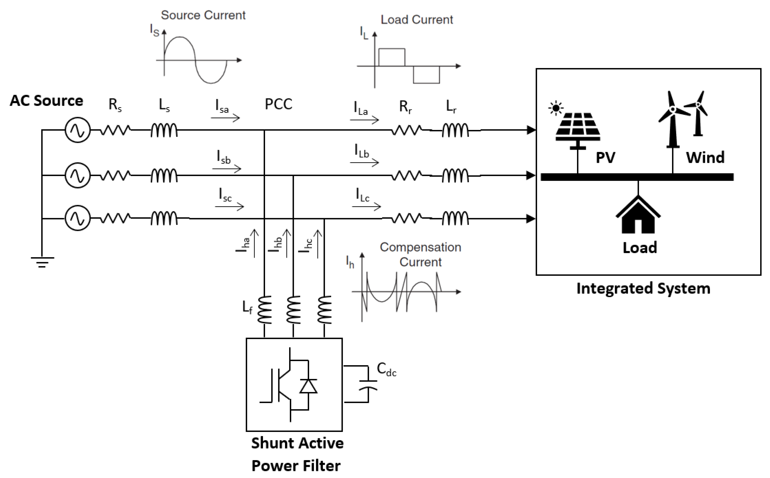
Figure 2.
Structure and control modules of the three-phase three-wire active power filter.

Figure 3.
VSI switches with the capacitor DC link.
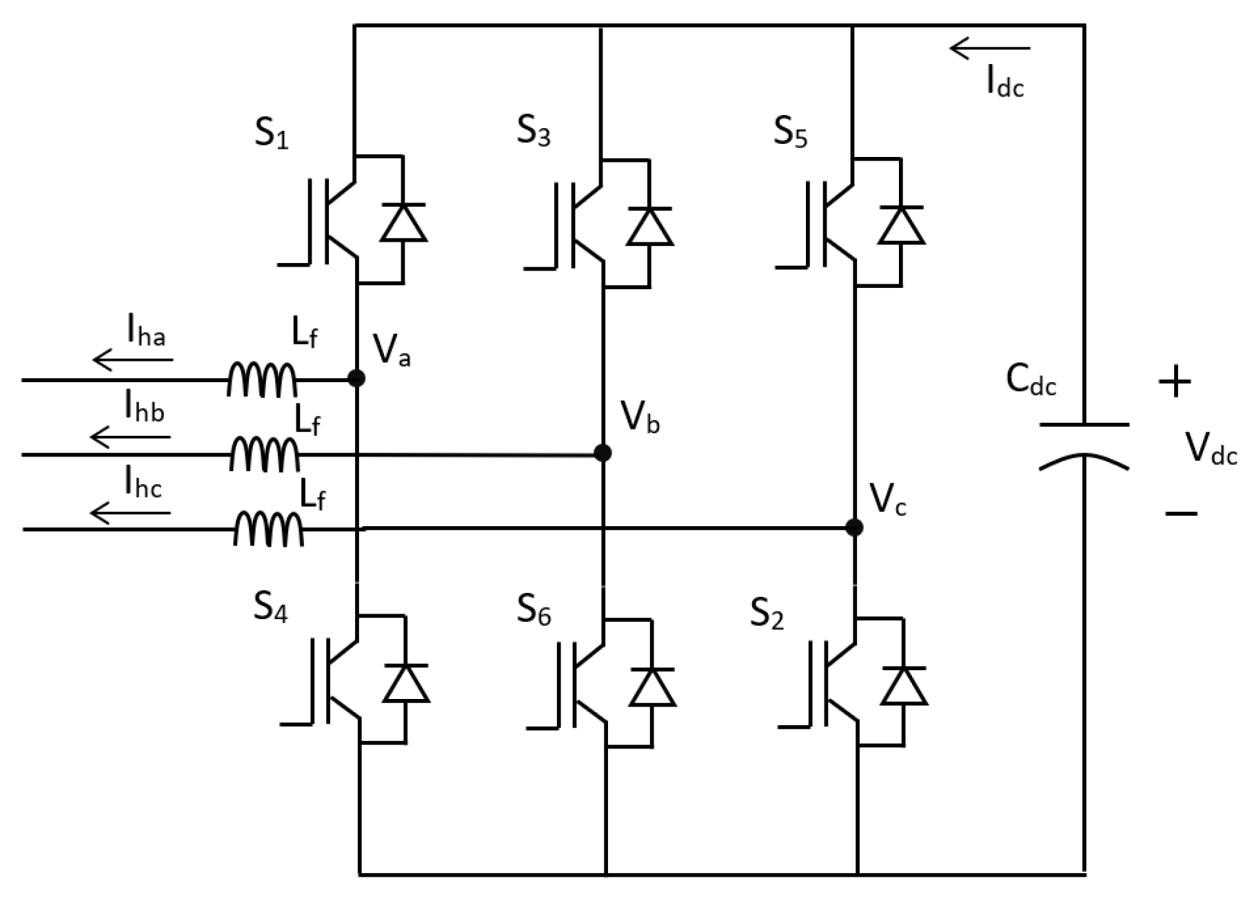
Figure 4.
DC link controller.

Figure 5.
Reference signal extraction block diagram using MPM.
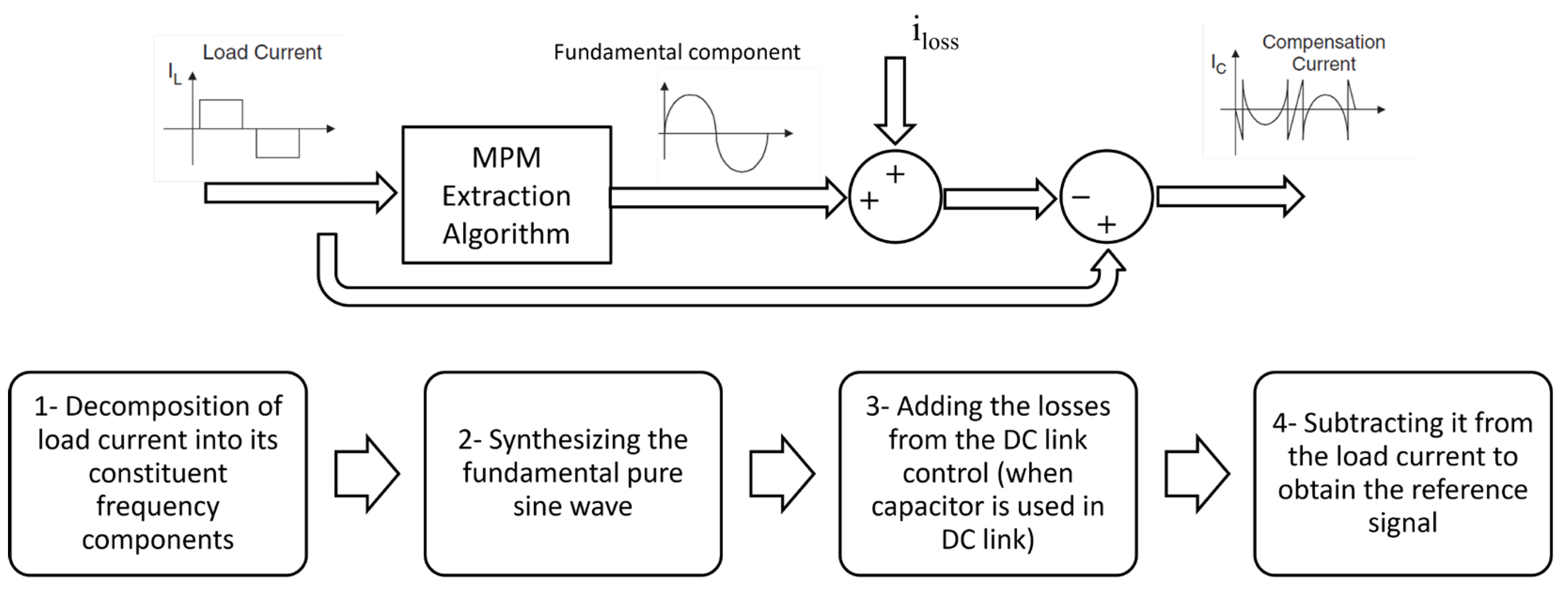
Figure 6.
MATLAB Simulink model of the SAPF using MPM.

Figure 7.
FFT analyzer with no filter used. (a) Source current waveform. (b) FFT window.

Figure 8.
Battery DC link FFT analyzer for source current with PWM control using (a) IRPT extraction technique, (b) SRF extraction technique, and (c) MPM extraction technique.
Figure 8.
Battery DC link FFT analyzer for source current with PWM control using (a) IRPT extraction technique, (b) SRF extraction technique, and (c) MPM extraction technique.
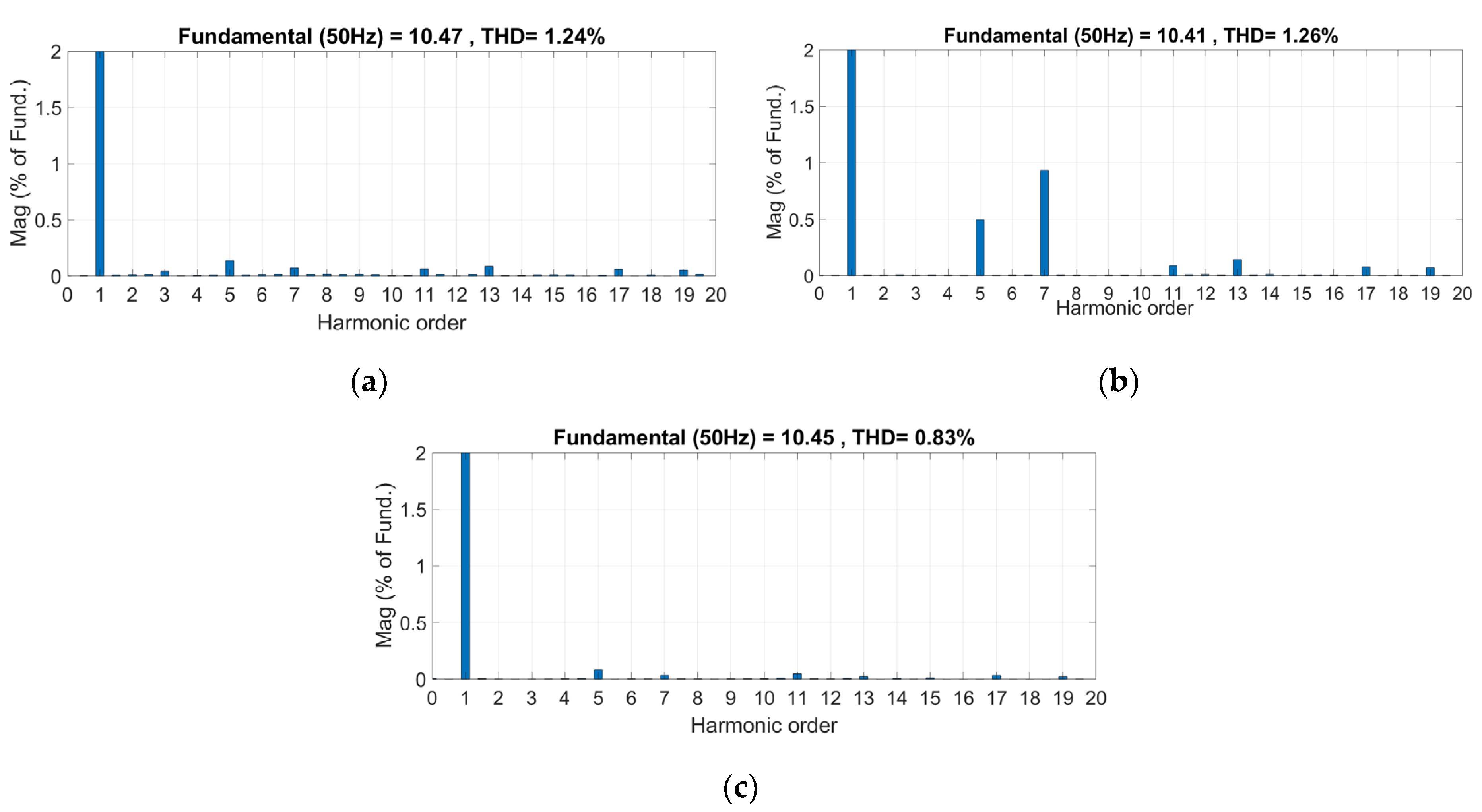
Figure 9.
Battery DC link waveforms of IL, Ih, and Is for SAPF with PWM control using (a) IRPT extraction, (b) SRF extraction, and (c) MPM extraction.
Figure 9.
Battery DC link waveforms of IL, Ih, and Is for SAPF with PWM control using (a) IRPT extraction, (b) SRF extraction, and (c) MPM extraction.

Figure 10.
Capacitor DC link FFT analyzer for SAPF with SVPWM control using (a) IRPT extraction (b) SRF extraction (c) MPM extraction.
Figure 10.
Capacitor DC link FFT analyzer for SAPF with SVPWM control using (a) IRPT extraction (b) SRF extraction (c) MPM extraction.

Figure 11.
Capacitor DC link Waveforms of IL, Ih, and Is for SAPF with SVPWM control using (a) IRPT extraction, (b) SRF extraction, and (c) MPM extraction.
Figure 11.
Capacitor DC link Waveforms of IL, Ih, and Is for SAPF with SVPWM control using (a) IRPT extraction, (b) SRF extraction, and (c) MPM extraction.
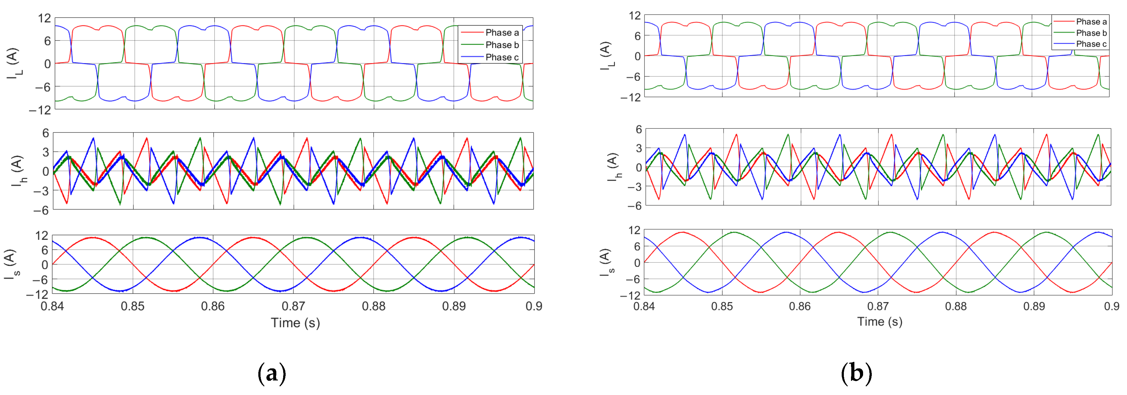

Figure 12.
DC-link capacitor’s voltage when using SVPWM control with (a) IRPT extraction, (b) SRF extraction, and (c) MPM extraction.
Figure 12.
DC-link capacitor’s voltage when using SVPWM control with (a) IRPT extraction, (b) SRF extraction, and (c) MPM extraction.
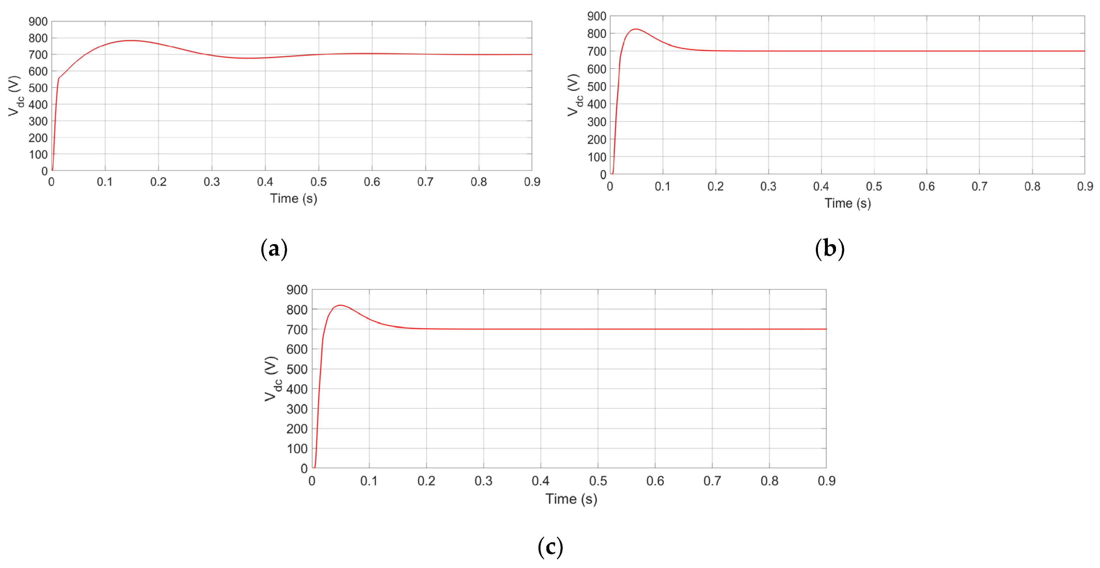
Figure 13.
FFT analyzer with no filter with the addition of load 2. (a) Source current waveform. (b) FFT window.
Figure 13.
FFT analyzer with no filter with the addition of load 2. (a) Source current waveform. (b) FFT window.
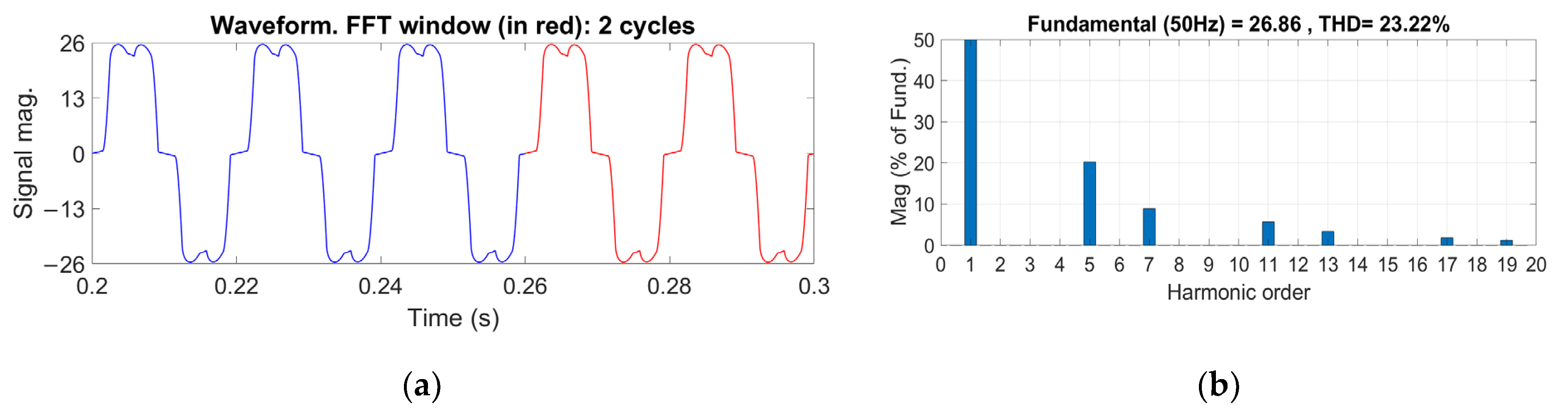
Figure 14.
Capacitor DC link FFT analyzer for SAPF with hysteresis control while adding load 2 using (a) IRPT extraction, (b) SRF extraction, and (c) MPM extraction.
Figure 14.
Capacitor DC link FFT analyzer for SAPF with hysteresis control while adding load 2 using (a) IRPT extraction, (b) SRF extraction, and (c) MPM extraction.

Figure 15.
Capacitor DC link waveforms of IL, Ih, Is, DC-link capacitor’s voltage value for SAPF with hysteresis control while adding load 2 using (a) IRPT extraction, (b) SRF extraction, and (c) MPM extraction.
Figure 15.
Capacitor DC link waveforms of IL, Ih, Is, DC-link capacitor’s voltage value for SAPF with hysteresis control while adding load 2 using (a) IRPT extraction, (b) SRF extraction, and (c) MPM extraction.

Figure 16.
Capacitor DC link FFT analyzer with no filter with the addition of load 3. (a) Source current waveform. (b) FFT window.
Figure 16.
Capacitor DC link FFT analyzer with no filter with the addition of load 3. (a) Source current waveform. (b) FFT window.
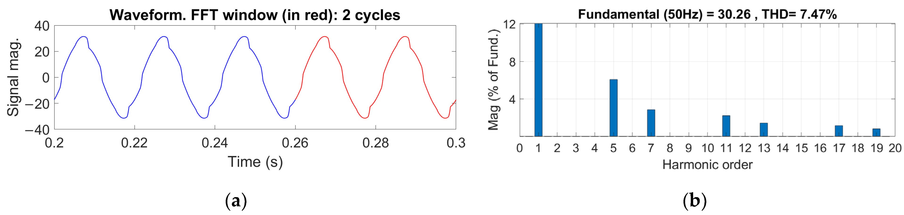
Figure 17.
Capacitor DC link FFT analyzer for SAPF with PWM control while adding load 3 using (a) IRPT extraction, (b) SRF extraction, and (c) MPM extraction.
Figure 17.
Capacitor DC link FFT analyzer for SAPF with PWM control while adding load 3 using (a) IRPT extraction, (b) SRF extraction, and (c) MPM extraction.
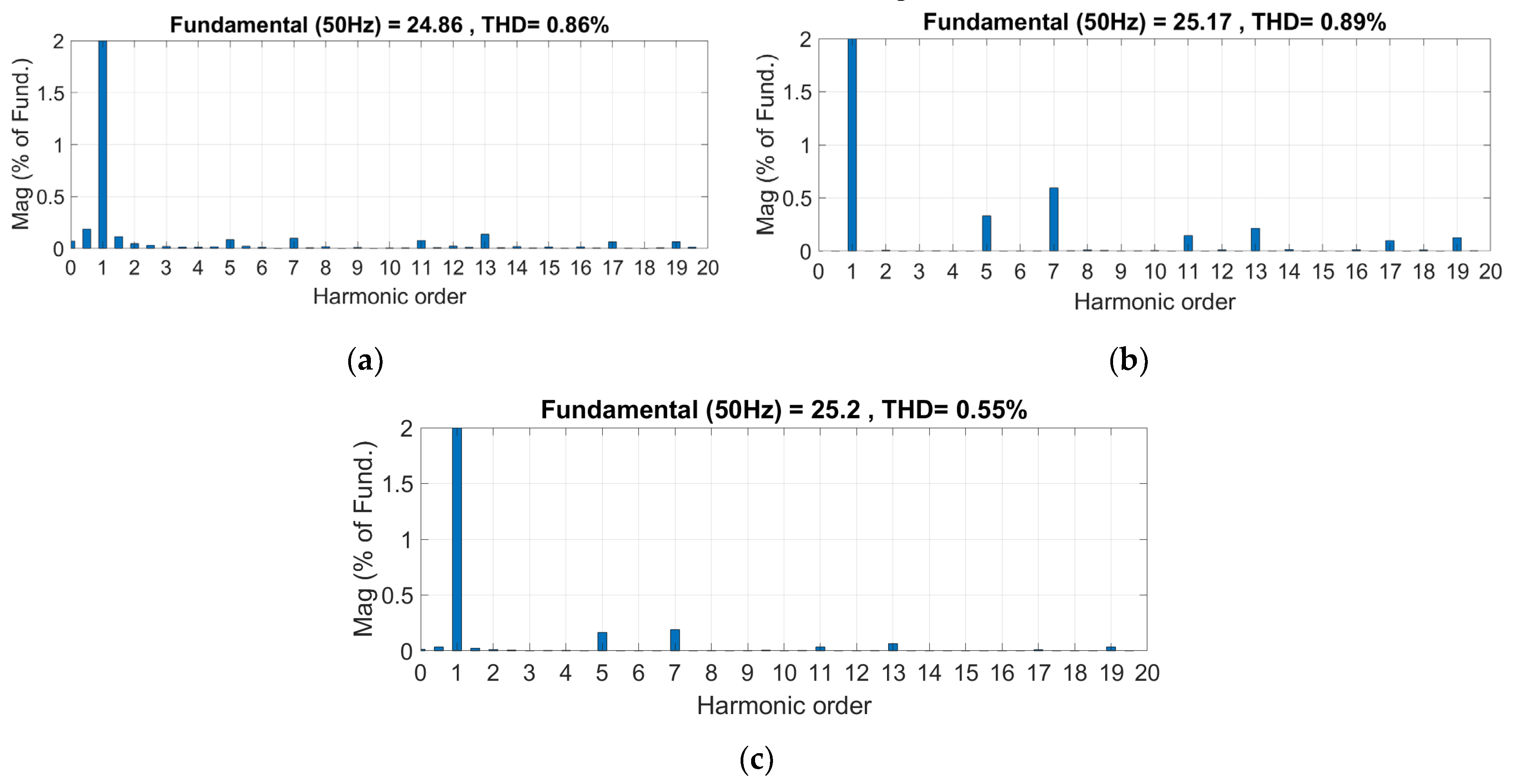
Figure 18.
PF with SAPF (using MPM) in red and without SAPF in blue.

Table 1.
Circuit parameters with load 1.
| Circuit Parameters | Parameter Value |
|---|---|
| Frequency | 50 Hz |
| Supply phase voltage peak value | 220 V |
| Source impedance (Rs, Ls) | 0.15 Ω, 0.03 mH |
| Line impedance (Rr, Lr) | 1 Ω, 1 mH |
| Coupling reactance | 3 mH |
| DC-link capacitance (Cdc) | 3000 µF |
| DC-link voltage reference (Vref) | 700 V |
| Load 1 impedance (RL, LL) | 40 Ω, 2 mH |
Table 2.
Battery DC link with load 1 results.
| Extraction Technique | % THD of Source Current | ||
|---|---|---|---|
| Hysteresis | PWM | SVPWM | |
| IRPT | 1.74% | 1.24% | 1.39% |
| SRF | 1.46% | 1.26% | 1.41% |
| MPM | 1.22% | 0.83% | 0.93% |
Table 3.
Capacitor DC link with load 1 results.
| Extraction Technique | % THD of Source Current | ||
|---|---|---|---|
| Hysteresis | PWM | SVPWM | |
| IRPT | 1.74% | 1.21% | 1.37% |
| SRF | 1.61% | 1.43% | 1.54% |
| MPM | 1.21% | 0.85% | 0.93% |
Table 4.
Capacitor DC link dynamic response results after load change.
| Extraction Technique | % THD of Source Current | ||
|---|---|---|---|
| Hysteresis | PWM | SVPWM | |
| IRPT | 1.04% | 0.85% | 0.88% |
| SRF | 1.51% | 1.52% | 1.61% |
| MPM | 0.64% | 0.52% | 0.55% |
Disclaimer/Publisher’s Note: The statements, opinions and data contained in all publications are solely those of the individual author(s) and contributor(s) and not of MDPI and/or the editor(s). MDPI and/or the editor(s) disclaim responsibility for any injury to people or property resulting from any ideas, methods, instructions or products referred to in the content. |
© 2023 by the authors. Licensee MDPI, Basel, Switzerland. This article is an open access article distributed under the terms and conditions of the Creative Commons Attribution (CC BY) license (https://creativecommons.org/licenses/by/4.0/).
Share and Cite
MDPI and ACS Style
Chahine, K.; Tarnini, M.; Moubayed, N.; El Ghaly, A. Power Quality Enhancement of Grid-Connected Renewable Systems Using a Matrix-Pencil-Based Active Power Filter. Sustainability 2023, 15, 887. https://doi.org/10.3390/su15010887
AMA Style
Chahine K, Tarnini M, Moubayed N, El Ghaly A. Power Quality Enhancement of Grid-Connected Renewable Systems Using a Matrix-Pencil-Based Active Power Filter. Sustainability. 2023; 15(1):887. https://doi.org/10.3390/su15010887
Chicago/Turabian StyleChahine, Khaled, Mohamad Tarnini, Nazih Moubayed, and Abdallah El Ghaly. 2023. "Power Quality Enhancement of Grid-Connected Renewable Systems Using a Matrix-Pencil-Based Active Power Filter" Sustainability 15, no. 1: 887. https://doi.org/10.3390/su15010887
Note that from the first issue of 2016, this journal uses article numbers instead of page numbers. See further details here.