

Long-Range Wireless Communication for In-Line Inspection Robot: 2.4 km On-Site Test
by
 ,
,
Huseyin Ayhan Yavasoglu
1,2,*,
Ilhami Unal
3,
Ahmet Koksoy
3,
Kursad Gokce
2 and
Yusuf Engin Tetik
2 1
Mechatronics Engineering, Mechanical Engineering, Yildiz Technical University, Istanbul 34349, Türkiye
2
TUBITAK Rail Transport Technologies Institute, Kocaeli 41470, Türkiye
3
TUBITAK Marmara Research Center, Kocaeli 41470, Türkiye
*
Author to whom correspondence should be addressed.
Sustainability 2023, 15(10), 8134; https://doi.org/10.3390/su15108134
Submission received: 14 January 2023
/
Revised: 10 April 2023
/
Accepted: 25 April 2023
/
Published: 17 May 2023
(This article belongs to the Special Issue Sustainable Development of Energy, Water and Environment Systems (SDEWES 2022))
Abstract
:This paper presents a study of the feasibility of using in-line inspection (ILI) techniques with long-range communication-capable robotic systems deployed with advanced inspection sensors in natural gas distribution pipelines, which are rare in the literature. The study involved selecting appropriate antennas and determining the appropriate communication frequency for an ILI robot operating on Istanbul 12″ and 16″ steel pipelines. The paper identifies the frequency windows with low losses, presents received signal strength indicator (RSSI) and signal-to-noise ratio (SNR) information for various scenarios, and evaluates the impact of T-junctions, which are known to be the worst components in terms of communication. To utilize the pipeline as a waveguide, low-attenuation-frequency windows were determined, which improved communication by a factor of 500 compared to aerial communication. The results of laboratory tests on a 50 m pipeline and real-world tests on a 2.4 km pipeline indicate that long-distance communication and video transmission are possible at frequencies of around 917 MHz with low-gain antennas. The study also assessed the impact of the early diagnosis of anomalies without incidents on the environment, achievable with ILI robots using long-range wireless communication.
1. Introduction
The transportation of natural gas and oil, both of which are potentially hazardous materials that can have significant environmental impacts, is commonly achieved through pipelines. According to the International Energy Agency (IEA), around 90% of natural gas is transported via pipelines globally [1]. The safe operation of pipelines is threatened by various factors, including corrosion, third-party damage, natural disaster, etc. [2]. Faults in natural gas pipelines are a threat to the energy supply’s continuity and can result in the catastrophic loss of life and property [3]. Therefore, it is essential to have a thorough understanding of the condition of pipelines in order to respond to emergency situations and prevent accidents and malfunctions. In summary, a maintenance and repair decision support system is necessary to ensure the safe and effective operation of these pipelines. When it comes to identifying pipeline anomalies, in-line inspection (ILI) methods are considered to be the most reliable, providing the most accurate results [4]. Pipelines are not harmed during ILI inspections. Therefore, these technologies are referred to as non-destructive testing (NDT) or non-destructive inspection (NDI) technologies [5]. Numerous ILI sensor technologies, including magnetic flux leakage (MFL) sensors [6], ultra-sonic sensors (UTs) [7], electro-magnetic acoustic transducers (EMATs) [8], and laser profilometers (LPs) [9], are used to detect faults during in-line inspections [10].
The applicability of in-line inspection technology extends beyond pipelines transporting hazardous materials, such as natural gas and oil, to include those conveying safe materials in water pipelines [11]. The material composition of the pipeline is a crucial factor in determining the appropriate sensor technology to be employed. Depending on the type of natural gas pipeline, the application of ILI sensors varies. On the other hand, the selection of the inspection tool that conveys the sensor is dependent on the characteristics of the pipeline itself. Natural gas pipelines can be broadly categorized into two distinct classifications: distribution and transmission lines. Transmission pipelines are typically larger than distribution pipelines and operate at higher pressures [12]. In contrast, the distribution system consists of smaller pipelines responsible for delivering natural gas to various end users, including commercial and residential buildings. The distinction between transmission and distribution pipelines is important as they have different design characteristics.
For transmission pipeline inspections, the high-sensitivity sensors are carried by tools called smart pigs [13] that move with the flow. One of the key advantages of these devices is their ability to operate autonomously, without the need for remote control. This eliminates the requirement for long-distance communication during their operation. Natural gas transmission lines are lengthy and uncomplicated, making them ideal for deploying self-contained smart pigs.
However, mostly, gas pipeline systems are not designed or constructed with ILI in mind. Distribution lines are particularly more complex, and they do not have the same structural characteristics as natural gas transmission lines. Due to the numerous special transitions and frequent diameter variations, smart pigs cannot be utilized in urban natural gas pipelines. Therefore, wireless robotic systems that can move independently of the gas flow, unlike smart pigs, are required for the ILI of city pipelines.
The scope of a robotic system capable of conducting inline inspections is extensive, encompassing a wide array of mechatronic systems with varying designs and capabilities. In a literature search conducted on this topic, numerous studies on pipeline inspection robotic systems were identified. For instance, the study [14] describes a fluid-driven small-size robotic system. The robot used in this study is more like the pig structure for transmission lines, and it is incompatible with distribution lines. The study [15] presents a crawler robot with three track-driving modules. This robot can be used in distribution lines but has a one-hour operating time and a short wireless range. Thus, it is better suited for visual inspections due to its lack of sophisticated sensors. The study [16] presents an automated vision-based navigation system for ILI pre-inspection. This is another small robotic application that drives on wheels rather than tracks. SAPER II [17] is an additional robotic system that inspects 4″ to 14″ natural gas pipelines and relies on a wire for power and communication.
However, these robotic systems do not include advanced sensor technology-based robotic systems, which are the subject of this study. The majority of these studies have focused on robotic systems that operate at close range and lack advanced sensors such as MFLs, UTs, and EMATs. In the literature, there are a few robotic systems equipped with MFL sensors that are capable of operating in natural gas distribution lines. One of these studies was on the Pibot robotic system, which is still in development [18]. The Pibot is a wireless [19] snake-like robot that is designed to operate in 16″ steel pipes. Pipetel Explorer robots, which are used commercially, are an additional example of a robotic application that employs an MFL sensor [20]. This family of robots has been adapted for different pipe diameters and is primarily employed in North American nations.
Robotic systems with sophisticated sensors and long-range wireless communication, the subject of this paper, are extremely rare in the scientific literature. This is because developing robots with advanced sensors capable of operating in natural gas distribution pipelines presents numerous challenges. Establishing a secure, long-distance connection between the robot and the control station could be regarded as one of the greatest challenges associated with the development of an ILI robot, such as the use of wireless relay [21] for small robots. Additionally, in [22], some bi-directional relay nodes were utilized for the long-distance communication of an inspection robot in a water distribution system. Thanks to the relay nodes, the robot switches its communication between transceivers during long-distance operation. For instance, in the study [23], an innovative concept of a robot chain for pipeline inspection based on wireless communication is presented. A robot chain is a subtype of a robot swarm in this context. These strategies are challenging to implement, as they require external structures in addition to the station and robot antenna and cause a delay in switching operations. Visible light communication (VLC) is a technique that can serve as an alternative to conventional RF communication strategies. For an actual visible light communication system, it is necessary to consider the uniformity of indoor illumination [24]. It is one of the newest technologies and has a high transmission rate and strong anti-interference capability. However, as given in the experimental study [25], VLC was developed for short- and middle-range data communication. In [26], a microwave communication system was developed for oil and gas pipelines with a good signal-to-noise ratio (SNR) (15 dB) at 2.4 GHz. However, this study presents 36 m straight pipeline communication and indicates that their proposed system can provide communication up to 150 m, which is a very short distance for ILI robots.
To increase the communication distance, there are two solutions using natural gas pipelines as a communication medium: a pipe as a waveguide for modems and a pipe as a signal conductor. A pipeline can act as a waveguide to frequencies in the few GHz range, which is suitable for commercially available radio modems. A pipeline can also support the direct signal injection of a signal with a frequency of a few kHz, which requires much more power for the same distance [26,27]. For example, in [28], a gas distribution pipeline was used as a communication channel to avoid installing a dedicated data transmission system. However, this research examined the transmission of data in the low-frequency band over a distance of approximately one kilometer. It was determined that the system under consideration was not capable of transmitting video, a crucial capability for ILI robots.
Despite the numerous studies in the literature on wireless communication, as highlighted above, there exists a gap in the ability to provide both long-distance transmission and video transmission capabilities. The implementation of ILI robots is hampered by this limitation.
Therefore, this study fills an important gap in this regard by examining the data-link system for long-distance communication without requiring an external structure. A preliminary version of the presented information was previously presented as a short paper at the 3rd Latin American Conference on Sustainable Development of Energy Water and Environmental Systems held in Sao Paulo [29].
The main contributions of this manuscript are as follows: (1) The introduction of a robot designed for deployment in pipelines with diameters of 12″ and 16″; (2) a detailed description of the antenna placement on the robot; (3) a comparison of the performance of the station antennas selected for use in steel natural gas pipelines, accompanied by test results of both 10 m and 50 m lines composed of pipes with 12″ and 16″ diameters; (4) an evaluation of the impact of T-junction pipe components on wireless communication; (5) the determination of the low-attenuation windows to select the proper communication frequency; (6) contrary to the studies in the literature that have utilized straight pipes, this study used an experimental on-site test on a real 2.4 km long pipeline with 42 bends and various special transitions; (7) an evaluation of the environmental implications of enabling ILI robot operations.
This paper is organized as follows: In Section 2, the robotic system and antenna installation are described. In Section 3, an analysis of the frequency range and antenna gain is given. In addition, the laboratory test results for 12-inch and 16-inch pipelines are discussed, and T-junction cases are evaluated. In Section 4, the conducted site test results on a real 12-inch steel gas pipeline are presented. In Section 5, the study’s impact on environmental consequences and major accidents is discussed. In Section 6, the impact of this study on natural gas distribution line-related accidents and environmental consequences are assessed. Finally, Section 7 presents the conclusion.
2. Robotic System
The natural gas inspection robot is designed in a modular manner and can move in both directions independently of the flow direction. It is classified as a snake robot with articulated joints. The articulation allows for multiple degrees of freedom within a single system, making its approach to obstacles extremely versatile.
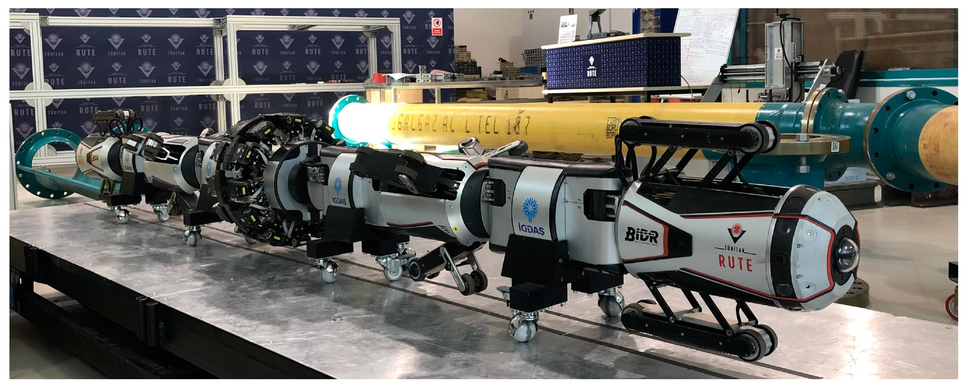
As depicted in Figure 1, the robot’s mechanical structure has been completed, and functional testing is currently in progress. The robot can automatically adapt to 12″ and 16″ pipe diameters by opening its arms based on the data it receives from force sensors. As illustrated in Figure 2, the mechanical structure consists of four distinct types of modules: Camera Modules, Driver Modules, Orientation Modules, and an MFL module. The front and the back modules of the robot are called Camera Modules, and they are equipped with custom-designed communication antennas. The robot communicates with the control station utilizing these antennas.
Camera Modules and Antenna Installation
The camera modules at both ends of the robot have a complex multi-joint structure and include several components: two arms with traction motors, a high-resolution fish-eye camera for image acquisition, a single board computer as a supervisory controller, an LED lighting unit for illumination, proximity sensors to avoid a collision during bend transitions, and a laser profiler to detect visual defects. A custom-designed communication antenna is also placed on the front of each camera module, as shown in Figure 3, to receive/transmit data between the robot and the station antenna.
3. Analysis of Frequency Range and Antenna Gain
To enable wireless communication between the robot and the station antenna over a long distance, the proper wave frequency must be chosen and the natural gas pipe used as a waveguide.
where is the radius of the waveguide, and is the zeros of the derivative of the Bessel function [18]. The propagation of waves can be either in the transverse electric (TE) mode or the transverse magnetic (TM) mode [30]. Since the permittivity (ε) and permeability (μ) of the natural gas are approximately the same as the ones of free space [31], the first propagating TE and TM modes and their cut-off frequencies for the 12-inch diameter circular waveguide are shown in Figure 4.
TE11 is the dominant mode. In reality, it is preferable to excite the circular waveguide with a 12-inch diameter between 585.67 MHz and 764.97 MHz for the lowest attenuation along the pipeline and polarization control. As the commercial transceiver communication modules available in the market operate mainly at the 868 MHz, 915 MHz, and 955 MHz central frequencies under 1 GHz, the excitation of one more mode, TM01, would be urgent considering not only higher losses but also dispersion and attenuation distortion to the signal since each exhibits different phase velocities and attenuation. Any propagating field in the circular waveguide (pipeline) is a superposition of the propagating modes existing for the frequency under consideration.
The TE11 dominant mode cut-off frequency of the 16-inch diameter circular waveguide is 390.7 MHz. The number of higher order modes that would be excited inside 16-inch diameter circular waveguides is at least four (TM01 = 510 MHz, TE21 = 647.4 MHz, TM11 = TE01 = 812.6 MHz, TE31 = 890.9 MHz, TM21 = 1090 MHz) under 1.1 GHz, compared to the only higher-order mode TM01 inside the 12-inch diameter circular waveguide. Due to the more common usage of underground circular pipes with a diameter of 12 inches for natural gas transportation in Turkey, fewer higher-order modes are excited compared to the 16-inch ones when commercial transceiver modules are utilized for communication inside the pipelines.
In addition to the aforementioned information, additional parameters are used to determine the quality of wireless communication. In wireless communication, the signal-to-noise ratio (SNR) and received signal strength indicator (RSSI) determine the quality and dependability of the communication channel [32,33]. The SNR is the ratio between the desired signal power and the noise power. It is a crucial metric for assessing the performance of communication. A high SNR value indicates a low noise level and high signal quality. The RSSI, on the other hand, is a measurement of the received signal’s strength. It is a relative measure of the signal strength that can be used to determine the distance between the receiver and the transmitter. A strong signal is indicated by a high RSSI value, while a weak signal is indicated by a low RSSI value. The SNR and RSSI are important parameters in wireless communication because they provide information about the signal’s quality and strength. In Section 4 and Section 5, these parameters are examined for multiple data-link cases using laboratory and field testing.
4. Laboratory Tests
To investigate the effects of antenna gain on the transmission performance inside the pipeline, two different ultra-wideband double-ridged antennas with high- and low-gain characteristics were used. As illustrated in Figure 5, the tests were initially conducted in pipelines that were constructed around the research center.
The measurement setup for the laboratory tests mainly consisted of an Agilent Vector Network Analyzer (VNA) E8361A (10 MHz–67 GHz). VNA measurements were performed for the frequency interval of 500 MHz to 3 GHz with an output power of +5 dBm. Each spectral measurement was represented with 401 equally spaced frequency points (data points) and 1 kHz IF bandwidth (BW) within the interval specified by the VNA. Therefore, a spectral resolution of 6.25 MHz was obtained. These parameters significantly reduced the noise floor and improved the dynamic range. Then, the measurement system, including the connectors and cables, was calibrated to remove the impairment caused by the components of each case of the laboratory experiments for reproducibility. The calibration data were saved to the internal memory of the Agilent VNA E8361A. The frequency interval was measured using the two different horn antennas that were attached to the VNA ports. The utilized low-gain antenna with a small aperture size operated between 0.9 and 18 GHz (1 dBi gain @ 915 MHz), and the high-gain antenna with a big aperture size operated between 0.5 and 4.5 GHz (10.5 dBi gain @ 915 MHz). The calibration data were removed from the measurement using its internal memory and a scattering parameter (S21) for transmission loss (or attenuation) in dB format for each data point.
Figure 6 compares the transmission loss within a 12-inch-diameter straight pipe when two antennas were utilized. Below 1.1 GHz, where the transmission loss was uniform and low, the communication channel within the circular waveguide was optimal, as depicted in the figure.
Although 12-inch diameter pipelines are widely used in Turkey, there are several subterranean transitions underground between 12-inch and 16-inch diameter pipes. If one observes 12-inch to 16-inch diameter transition losses, they are not greater than 0.5–1.0 dB between a frequency range of 750 MHz and 950 MHz in application compared to the losses for the same-length straight pipelines with a 12-inch diameter (Figure 7).
As shown in Figure 7, comparing the communication loss over air to that within a circular waveguide with a 12-inch diameter at a distance of 10 m revealed a minimum increase of 25 dB inside the pipeline, which corresponded to a 500-fold improvement in communication performance.
Attenuation tests were also conducted in a 50 m long pipeline, including both 12″ and 16″ straight pipelines with bend and transition parts that were constructed around the research center, as shown in Figure 8. The pipeline under test comprised eight 12-inch pipe sections, two 16-inch pipe sections, and two elbow joints. As depicted in Figure 8, the 12-inch pipes are denoted by yellow, while the 16-inch pipes are represented by blue.
In this case, new VNA measurements were performed for the frequency interval of 900 MHz to 930 MHz, with a higher spectral resolution of 0.25 MHz. The attenuation test results for the 50 m length test pipeline located in front of the laboratory were analyzed both with respect to the frequency and the distance/length. The evaluation results, as a function of frequency for the different lengths of the test pipelines, are presented in Figure 9, while the results based on distance for different frequency ranges are shown in Figure 10.
According to the attenuation results with respect to frequency, there were four low attenuation windows that were suitable to communicate efficiently inside the pipelines (Figure 9). It is also obvious that the attenuation level on average increased, as the pipeline became longer for those three low attenuation windows (Figure 10).
In another measurement study, the transmission characteristics of three different T-junction cases with different antenna gains were investigated over 500 MHz to 1 GHz, with a spectral resolution of 6.25 MHz (Figure 11). Three types of antennas were attached to the VNA ports, as shown in Table 1, including low-gain (1 dBi), middle-gain (4 dBi), and high-gain (10.5 dBi) double-ridged antennas.
Figure 12 depicts the test pipeline designed to examine communication in three distinct scenarios for T-junctions, one of the worst wireless communication components.
Figure 13 only depicts the transmission response (loss) for the high-gain antenna because the graphs obtained from the tests conducted with three different antennas have comparable characteristics. Information about the tests conducted with other antennas is provided in the text that follows.
The transmission response (loss) in Figure 13 shows major attenuation (at least under −30 dB) at the central frequency of 737.5 MHz. Similarly, the transmission response for the vertical polarization of high-gain antennas shows major attenuation at the central frequency of 914.5 MHz. On the other hand, the transmission response for both the vertical and horizontal polarizations of the middle-gain antennas shows major attenuation at the central frequency of 738 MHz. Finally, the transmission response for the vertical and horizontal polarizations of the low-gain antennas shows major attenuation at the central frequencies of 918.7 MHz and 737.5 MHz, respectively.
5. On-Site Test Measurements
As shown in Figure 14, real pipeline tests were conducted by installing antennas and measuring equipment (spectrum analyzer) at both ends of the pipeline.
Due to the uniform and low-loss-transmission characteristics for the frequency band under 1.1 GHz, Microhard pDDL900—Dual Frequency OEM Ethernet and Serial Digital Data Link modules and accompanying evaluation boards were selected for the site measurements of the features of a 900 MHz frequency band of operation and its adjustable output power (up to 1 W).
The preferred digital data link module for wireless communication was developed to provide flexibility within the 900 MHz frequency band (ranging from 902–928 MHz). This module has a maximum data rate of 25 Mbps, enabling the testing of various frequencies at various output power levels within a natural gas distribution pipeline. Here, the 2.4-km-long test pipeline contained 42 bends and 3 specialized transitions (such as river and railway crossings). The chosen pipeline contained numerous challenging pipe components and special transitions, and it was essential to evaluate how transmission can be achieved even under the most challenging conditions.
Two distinct ultra-wideband double-ridged antennas with high- and low-gain characteristics were used for the site measurements. These measurements were also carried out by considering different polarizations and a different selection (Tx/Rx) of antennas at a 917 MHz central frequency with a 6 MHz bandwidth (one of the three low-attenuation windows depicted in Figure 9) and 1 W (30 dBm) of output power. The received signal strength indicator (RSSI) [21] and signal-to-noise ratio (SNR) results of the conducted tests are given in Table 1. The SNR indicates how much the signal level was greater than the noise level. The higher the ratio (above 10 dB), the better the signal quality [34]. The digital modulation type was also set as adaptive to obtain the best SNR in each site measurement test.
6. Discussion
This section discusses the findings of the study and also addresses the possibility of reducing environmental consequences through the early detection of anomalies by utilizing ILI robots that can be deployed after long-range wireless communication capabilities have been established.
Limited research has been conducted on the application of pipeline monitoring for both water and gas distribution networks. The existing research has examined the viability of wireless propagation over 100 m at a frequency of 2.5 GHz [35] and the wireless control of an in-pipe robot at a lower frequency of 434 MHz [22]. Our study, however, presents measurements conducted on-site that demonstrate satisfactory results for communication at the central frequency of 917 MHz over a significantly longer range of 2400 m.
6.1. Frequency and Antenna Selection
The output power of the transmitter is an important factor to consider during testing. The tests were conducted at 30 dBm, which is comparable to the 25 dBm [35] level used in similar studies. Wireless communication systems can employ different frequency bands depending on the amount of data to be transmitted and the range of communication. For low-data-rate applications where a narrow bandwidth is sufficient, 100 kHz [36] frequencies can be used, whereas for short-range communications requiring high data rates, higher frequencies, such as 2.4 GHz [35,37], can be chosen. The results of the laboratory tests have provided us with crucial information regarding frequency selection. It is obvious that the use and selection of high-gain antennas for pipeline communication were better in terms of the obtained lower transmission loss. In addition, the transmission losses randomly varied and fluctuated over the frequency band due to the higher-order modes excited approximately after 1.1 GHz. Hence, it is obvious that it was hard to communicate properly after 1.1 GHz inside the 12-inch diameter pipes due to the big amount of ripples of losses at higher-frequency regions. The lower-frequency band (under 1.1 GHz) led to a better communication channel inside the circular waveguide, in terms of uniform and low-loss transmission characteristics over its related frequency band.
In the context of this study, considering the transmission of communication over the air and from different pipe diameters, the scope of this study permits the presentation of the following findings: 12-inch to 16-inch diameter transitions and their straight pipeline equivalents showed almost similar transmission loss characteristics. This would allow for the use of a number of needed 12-inch to 16-inch diameter transitions underground. Moreover, when the free-space communication loss over the air is compared to that inside the 12-inch diameter straight circular waveguide from the same distance (10 m), it is obvious that the dynamic range would be at least 25 dB greater inside the pipeline or circular waveguide. This corresponds to communication performance that is approximately 500 times superior within the pipeline compared to communication in free space (over air).
According to the attenuation tests employed in this study, our analysis allows us to draw the following conclusions: There were three wide low-attenuation windows in terms of bandwidth, including 906–912 MHz, 914–920 MHz, and 922–928 MHz. It is also evident that the average attenuation level increased as the pipeline lengthened for the three low-attenuation windows. According to the test results, it appears that electromagnetic waves within the pipelines were attenuated by approximately 0.5 dB per 5 m on average.
The examination of wireless communication in the T-junctions shows that it is among the most important parts of data-link systems because these components are the most likely to degrade wireless communication along the transmission path. Due to the fact that there are three different directions in the pipeline containing T-junctions, the results varied depending on which ends of the pipe were communicated. Therefore, in this study, tests were conducted for three distinct scenarios. Consequently, although the T-junctions negatively impacted the wireless communication, the worst-case scenario was when the station antenna and robot did not communicate in the same direction. In this study, it was determined that the Case 1 and Case 3 scenarios significantly degraded the wireless communication. When these tests were repeated with three distinct antenna types, similar results were obtained, and significant attenuation was observed regardless of the antenna type.
As testing in a real pipeline is not always possible, the findings presented in this study are of critical importance. In pipelines with a high degree of complexity, including numerous elbows, valves, and specialized transitions in addition to straight lines, the antenna, polarization, and frequency selection become of the utmost importance. Considering the measurement results given in this study, it was possible to communicate with the lowest-gain antennas at both the Tx and Rx sites, even regardless of the polarization (V: Vertical, H: Horizontal), at a distance of 2.4 km inside the pipeline, despite containing 42 bends and 3 special transitions. Additionally, live footage was successfully transferred via a 2.4-km-long pipeline.
6.2. The Study’s Impact on Environmental Consequences and Major Accidents
Pipelines are widely acknowledged as a dependable and efficient method of energy transmission with minimal environmental impact if they are properly operated and maintained. However, accidents and malfunctions in pipelines can have severe consequences, resulting in substantial harm to human life and the environment. In natural gas and oil pipelines, where explosions and environmental contamination, respectively, can occur as a result of these incidents, the effects can be especially pronounced.
In accordance with regulatory frameworks, operators must consistently identify and manage risks associated with pipeline segments located in high-consequence areas (HCAs), where any untoward incident can have a significant impact on public safety and the environment. As a crucial component of pipeline integration management (PIM), pipeline defects and anomalies are meticulously analyzed and promptly remedied. This proactive approach ensures that the pipeline system operates safely and sustainably. Notably, PIM requirements have been in effect since 2002 for all hazardous liquid pipelines, since 2004 for natural gas transmission pipelines, and since 2010 for natural gas distribution pipelines in accordance with American regulations [35].
Figure 15 demonstrates that, as a result of integrity management, the environmental impacts of both natural gas and oil pipelines have decreased despite their growing lengths.
Based on Pipeline and Hazardous Materials Safety Administration (PHMSA) data [38], which are presented in Figure 15, it can be observed that serious accidents are decreasing due to pipeline inspections and PIM. As a part of PIM, the ILI approach produces the most precise and reliable results when conducting pipeline inspection activities [39]. ILI techniques in distribution lines can only be executed by robots, but the difficulty of wireless communication over long distances precludes their use. As a result, this enhancement could be accomplished using ILI techniques that are only applied to gas transmission lines.
This study presents a long-range communication for robotic systems that enables the utilization of robots on unpiggable natural gas distribution pipelines. By implementing this method, inspections that are more accurate can be performed, and more efficient and organized responses to pipeline issues can be achieved. As a result, unnecessary excavations and fugitive gas emissions into the atmosphere will be reduced. Additionally, this approach has the potential to mitigate the occurrence of accidents and decrease the environmental impact, particularly for older pipelines. Overall, this approach not only ensures the continuity of a gas supply but also promotes safety and environmental sustainability.
7. Conclusions
In conclusion, the study has demonstrated the viability and significance of employing ILI robots in natural gas pipelines to address the problem of long-range wireless communication.
The laboratory tests on pipelines with 12″ and 16″ diameters and 10 m and 50 m lengths revealed that communication losses occurred despite the use of various antenna types, particularly at T-junction transitions. It is the worst-case scenario for communication to change planes, particularly at T-junction transitions. However, utilizing the pipeline as a waveguide and selecting frequencies below 1.1 GHz has the potential to improve communication by a factor of 500 when compared to airborne communication. In addition, low-gain antennas were able to successfully transmit video transmission over a pipeline length of 2.4 km with 42 bends and 3 special transitions at 917 MHz, which was selected based on the identification of the low-attenuation windows.
Our findings indicate that a signal-to-noise ratio (SNR) slightly above 10 dB is required for high-quality long-range communication within a pipeline. Low-gain antennas with V-V/H-H polarization could transmit up to 2.4 km, whereas antennas with higher gain and vertical polarization improved communication quality. Despite the pipeline’s irregularities, the reliable on-site measurements indicate promising results for vertically polarized communication in the 914–920 MHz range.
ILI technology has a substantial influence on reducing fatal and severe injuries and preventing accidents with negative environmental impacts. The results of this study provide significant findings for incorporating ILI technology into distribution lines through the use of robots.
Author Contributions
Conceptualization, H.A.Y. and I.U.; methodology, I.U. and A.K.; software, Y.E.T. and A.K.; validation, I.U. and A.K.; investigation, I.U.; writing—original draft preparation, H.A.Y. and I.U.; writing—review and editing, all authors; supervision, H.A.Y.; project administration, H.A.Y. and K.G. All authors have read and agreed to the published version of the manuscript.
Funding
This research received no external funding.
Informed Consent Statement
Not applicable.
Data Availability Statement
The data used to support the finding of this study are available from the corresponding author upon approval of the project’s administration.
Acknowledgments
This work was performed under the “Pipeline Inspection Robot for 12-inch and 16-inch Natural Gas Distribution Pipe-lines” project, which is supported and financed by IGDAS, a gas distribution company located in Istanbul, Turkey. The inspection robot was designed and developed by the Robotics and Smart Systems Department of TUBİTAK RUTE.
Conflicts of Interest
The authors declare no conflict of interest.
Nomenclature
| EMAT | Electromagnetic Acoustic Transducer |
| HCA | High-Consequence Areas |
| ILI | In-Line Inspection |
| LP | Laser Profilometer |
| MFL | Magnetic Flux Leakage |
| NDI | Non-Destructive Inspection |
| NDT | Non-Destructive Testing |
| PIM | Pipeline Integrity Management |
| PHMSA | Pipeline and Hazardous Materials Safety Administration |
| RSSI | Received Signal Strength Indicator |
| SNR | Signal-to-Noise Ratio |
| TE | Transverse Electric |
| TM | Transverse Magnetic |
| UT | Ultrasonic Testing |
| VLC | Visible Light Communication |
| Radius of a Waveguide | |
| ε | Permittivity |
| Bessel Function | |
| μ | Permeability |
| Zeros of the Derivative |
References
- IEA World Energy Outlook 2020. Available online: https://www.iea.org/reports/world-energy-outlook-2020 (accessed on 2 December 2022).
- Zhang, M.; Ling, J.; Tang, B.; Dong, S.; Zhang, L. A Data-Driven Based Method for Pipeline Additional Stress Prediction Subject to Landslide Geohazards. Sustainability 2022, 14, 11999. [Google Scholar] [CrossRef]
- Fang, W.; Wu, J.; Bai, Y.; Zhang, L.; Reniers, G. Quantitative Risk Assessment of a Natural Gas Pipeline in an Underground Utility Tunnel. Process Saf. Prog. 2019, 38, e12051. [Google Scholar] [CrossRef]
- Geng, L.; Dong, S.; Qian, W.; Peng, D. Image Classification Method Based on Improved Deep Convolutional Neural Networks for the Magnetic Flux Leakage (MFL) Signal of Girth Welds in Long-Distance Pipelines. Sustainability 2022, 14, 12102. [Google Scholar] [CrossRef]
- Aldosari, H.; Elfouly, R.; Ammar, R. Evaluation of Machine Learning-Based Regression Techniques for Prediction of Oil and Gas Pipelines Defect. In Proceedings of the 2020 International Conference on Computational Science and Computational Intelligence (CSCI), Las Vegas, NV, USA, 16–18 December 2020; IEEE: Piscataway, NJ, USA, 2020; pp. 1452–1456. [Google Scholar]
- Long, Y.; Huang, S.; Peng, L.; Wang, W.; Wang, S.; Zhao, W. Internal and External Defects Discrimination of Pipelines Using Composite Magnetic Flux Leakage Detection. In Proceedings of the 2021 IEEE International Instrumentation and Measurement Technology Conference (I2MTC), Glasgow, UK, 17–20 May 2021; IEEE: Piscataway, NJ, USA, 2021; pp. 1–6. [Google Scholar]
- Norli, P.; Vallee, E.; Aanes, M.; Prieur, F.; Bjastad, T.G.; Standal, O.K.-V.; Brende, O.M.; Frijlink, M. Ultrasonic Detection of Crack Defects in Pipe Samples with a 132-Channel Test Scanner in Gas. In Proceedings of the 2020 IEEE International Ultrasonics Symposium (IUS), Las Vegas, NV, USA, 7–11 September 2020; IEEE: Piscataway, NJ, USA, 2020; pp. 1–4. [Google Scholar]
- Xie, M.; Tian, Z. A Review on Pipeline Integrity Management Utilizing In-Line Inspection Data. Eng. Fail. Anal. 2018, 92, 222–239. [Google Scholar] [CrossRef]
- Zhang, S. Absolute Phase Retrieval Methods for Digital Fringe Projection Profilometry: A Review. Opt. Lasers Eng. 2018, 107, 28–37. [Google Scholar] [CrossRef]
- Rusu, C.; Tatar, M.O. Adapting Mechanisms for In-Pipe Inspection Robots: A Review. Appl. Sci. 2022, 12, 6191. [Google Scholar] [CrossRef]
- Durai, M.; Chi-Chuan, P.; Lan, C.W.; Chang, H. Analysis of Leakage in a Sustainable Water Pipeline Based on a Magnetic Flux Leakage Technique. Sustainability 2022, 14, 11853. [Google Scholar] [CrossRef]
- Anderson, D.A. Natural Gas Transmission Pipelines: Risks and Remedies for Host Communities. Energies 2020, 13, 1873. [Google Scholar] [CrossRef]
- Zhang, X.; Zhang, B.; Jin, Y.; Li, B.; Li, R.; Zhang, L.; Song, Q.; Zhao, X. Analysis of Rotation of Pigs during Pigging in Gas Pipeline. In Proceedings of the 2015 International Conference on Fluid Power and Mechatronics (FPM), Harbin, China, 5–7 August 2015; IEEE: Piscataway, NJ, USA, 2015; pp. 892–895. [Google Scholar]
- Zhu, X.; Wang, W.; Zhang, S.; Liu, S. Experimental Research on the Frictional Resistance of Fluid-Driven Pipeline Robot with Small Size in Gas Pipeline. Tribol. Lett. 2017, 65, 49. [Google Scholar] [CrossRef]
- Zhao, W.; Zhang, L.; Kim, J. Design and Analysis of Independently Adjustable Large In-Pipe Robot for Long-Distance Pipeline. Appl. Sci. 2020, 10, 3637. [Google Scholar] [CrossRef]
- Karkoub, M.; Bouhali, O.; Sheharyar, A. Gas Pipeline Inspection Using Autonomous Robots with Omni-Directional Cameras. IEEE Sens. J. 2021, 21, 15544–15553. [Google Scholar] [CrossRef]
- Kashyap, R.; Kashyap, R.; Kumbhar, R.; Chari, A. Design of Reconfigurable In-Pipe Exploration Robots. In Proceedings of the 2018 International Conference on Current Trends towards Converging Technologies (ICCTCT), Coimbatore, India, 1–3 March 2018; IEEE: Piscataway, NJ, USA, 2018; pp. 1–6. [Google Scholar]
- Kim, D.-K.; Yoo, H.-R.; Cho, S.-H.; Koo, S.-J.; Kim, D.-K.; Yoo, J.-S.; Rho, Y.-W. Inspection of Unpiggable Natural Gas Pipelines Using In-Pipe Robot BT. In AETA 2016: Recent Advances in Electrical Engineering and Related Sciences; Duy, V.H., Dao, T.T., Kim, S.B., Tien, N.T., Zelinka, I., Eds.; Springer International Publishing: Cham, Switzerland, 2017; pp. 364–373. [Google Scholar]
- Kim, D.-K.; Yoo, H.-R.; Yoo, J.-S.; Kim, D.-K.; Cho, S.-H.; Koo, S.-J.; Woo, R.-Y.; Jung, H.-K. Development of MFL System for In-Pipe Robot for Unpiggable Natural Gas Pipelines. In Proceedings of the 2013 10th International Conference on Ubiquitous Robots and Ambient Intelligence (URAI), Jeju, Republic of Korea, 30 October–2 November 2013; IEEE: Piscataway, NJ, USA, 2013; pp. 51–54. [Google Scholar]
- Mills, G.; Jackson, A.; Richardson, R. Advances in the Inspection of Unpiggable Pipelines. Robotics 2017, 6, 36. [Google Scholar] [CrossRef]
- Zhao, W.; Kamezaki, M.; Yoshida, K.; Konno, M.; Onuki, A.; Sugano, S. An Automatic Tracked Robot Chain System for Gas Pipeline Inspection and Maintenance Based on Wireless Relay Communication. In Proceedings of the 2018 IEEE/RSJ International Conference on Intelligent Robots and Systems (IROS), Madrid, Spain, 1–5 October 2018; IEEE: Piscataway, NJ, USA, 2018; pp. 3978–3983. [Google Scholar]
- Kazeminasab, S.; Kathrine Banks, M. A Localization and Navigation Method for an In-Pipe Robot in Water Distribution System through Wireless Control towards Long-Distance Inspection. IEEE Access 2021, 9, 117496–117511. [Google Scholar] [CrossRef]
- Zhao, W.; Kamezaki, M.; Yoshida, K.; Konno, M.; Toriumi, R.; Sugano, S. A Reliable Communication and Localization Method for Gas Pipeline Robot Chain Based on RSSI Theory. In Proceedings of the 2017 IEEE/SICE International Symposium on System Integration (SII), Taipei, Taiwan, 11–14 December 2017; IEEE: Piscataway, NJ, USA, 2017; pp. 282–287. [Google Scholar]
- Zhang, X.; Zhao, N.; Al-Turjman, F.; Khan, M.B.; Yang, X. An Optimization of the Signal-to-Noise Ratio Distribution of an Indoor Visible Light Communication System Based on the Conventional Layout Model. Sustainability 2020, 12, 9006. [Google Scholar] [CrossRef]
- Zhao, W.; Kamezaki, M.; Yoshida, K.; Yamaguchi, K.; Konno, M.; Onuki, A.; Sugano, S. A Preliminary Experimental Study on Control Technology of Pipeline Robots Based on Visible Light Communication. In Proceedings of the 2019 IEEE/SICE International Symposium on System Integration (SII), Paris, France, 14–16 January 2019; IEEE: Piscataway, NJ, USA, 2019; pp. 22–27. [Google Scholar]
- Kossenas, K.; Podilchak, S.K.; Beveridge, M. Microwave System Development for Wireless Communications Inside Oil and Gas Well Pipelines. IEEE J. Microw. 2022, 3, 553–569. [Google Scholar] [CrossRef]
- Erickson, K.T.; Miller, A.E.; Stanek, E.K.; Wu, C.H.; Dunn-Norman, S. 1 Pipelines as Communication Network Links Final Report for the Period 1 October 2002 to 30 November 2004. 2005. Available online: https://www.semanticscholar.org/paper/1-Pipelines-as-Communication-Network-Links-Final-1-Erickson-Miller/cd037b824974ea79af720d202520421f48827b8b (accessed on 2 December 2022).
- Caruso, P.; Iacono, S.D.; Di Caro, D.; Paciello, V. Improvement of Communication Distance for an Unconventional Channel. In Proceedings of the 2022 IEEE International Instrumentation and Measurement Technology Conference (I2MTC), Ottawa, ON, Canada, 16–19 May 2022; pp. 5–10. [Google Scholar] [CrossRef]
- Yavasoglu; Ayhan, H.; Unal, I.; Koksoy, A.; Tetik, Y.E. Long Range Wireless Communication for Natural Gas Pipeline Inspection Robot. In Proceedings of the 3rd Latin American Conference on Sustainable Development of Energy Water and Environmental Systems, Sao Paulo, Brazil, 24–28 July 2022. [Google Scholar]
- Balanis, C.A. Advanced Engineering Electromagnetics, 2nd ed.; Wiley: New York, NY, USA, 1989. [Google Scholar]
- Schmidt, J.W.; Moldover, M.R. Dielectric Permittivity of Eight Gases Measured with Cross Capacitors. Int. J. Thermophys. 2003, 24, 375–403. [Google Scholar] [CrossRef]
- Hassan, M.; Singh, M.; Hamid, K.; Saeed, R.; Abdelhaq, M.; Alsaqour, R. Design of Power Location Coefficient System for 6G Downlink Cooperative NOMA Network. Energies 2022, 15, 6996. [Google Scholar] [CrossRef]
- Perković, T.; Dujić Rodić, L.; Šabić, J.; Šolić, P. Machine Learning Approach towards LoRaWAN Indoor Localization. Electronics 2023, 12, 457. [Google Scholar] [CrossRef]
- Wang, J.; Li, B.; Liu, M.; Li, J. SNR Estimation of Time-Frequency Overlapped Signals for Underlay Cognitive Radio. IEEE Commun. Lett. 2015, 19, 1925–1928. [Google Scholar] [CrossRef]
- Kossenas, K.; Podilchak, S.K.; Beveridge, M. Wireless Propagation in a Metallic Pipe for the Transmission of Sensory Oil and Gas Well Data. IEEE Antennas Wirel. Propag. Lett. 2022, 21, 1124–1128. [Google Scholar] [CrossRef]
- Akafua, J.; Chapman, R.; Guo, H. A Design of Wireless Communication and Wireless Energy Transfer System for In-Pipe Robots. In Proceedings of the 2021 IEEE International Conference on Wireless for Space and Extreme Environments (WiSEE), Cleveland, OH, USA, 12–14 October 2021; IEEE: Piscataway, NJ, USA, 2021; pp. 84–89. [Google Scholar]
- Ogai, H.; Wada, K.; Hirai, K.; Abe, T.; Sato, G. Wireless Radio Communication System for a Pipe Inspection Robot. In Proceedings of the 2007 International Conference on Control, Automation and Systems, Seoul, Republic of Korea, 17–20 October 2007; IEEE: Piscataway, NJ, USA, 2007; pp. 2616–2619. [Google Scholar]
- PHMSA Pipeline Incidents 20 Year Trends. Available online: https://www.phmsa.dot.gov/data-and-statistics/pipeline/pipeline-incident-20-year-trends (accessed on 10 December 2022).
- United States Government Accountability Office. Pipeline Safety Report. 2015. Available online: https://www.gao.gov/assets/gao-15-843t.pdf (accessed on 10 December 2022).
Figure 1.
The natural gas inspection robot.

Figure 2.
Modules of the in-line inspection robot.

Figure 3.
Camera module and communication antenna.

Figure 4.
The first propagating modes and their cut-off frequencies for a circular waveguide with a 12-inch diameter.
Figure 4.
The first propagating modes and their cut-off frequencies for a circular waveguide with a 12-inch diameter.

Figure 5.
Laboratory test pipeline.

Figure 6.
Transmission loss (dB) characteristics with respect to frequency between high- and low-gain antennas.
Figure 6.
Transmission loss (dB) characteristics with respect to frequency between high- and low-gain antennas.

Figure 7.
Transmission loss (dB) measurements using high-gain antennas among 12″ straight pipelines, 12″–16″ transitions, and free-space cases.
Figure 7.
Transmission loss (dB) measurements using high-gain antennas among 12″ straight pipelines, 12″–16″ transitions, and free-space cases.

Figure 8.
Laboratory 50 m 12″ and 16″ steel gas test pipelines.

Figure 9.
Attenuation results as a function of frequency for different lengths of test pipelines.

Figure 10.
Attenuation test results as a function of distance/length for different frequency ranges on average.
Figure 10.
Attenuation test results as a function of distance/length for different frequency ranges on average.

Figure 11.
Low-, middle-, and high-gain antennas used in the measurements: (a) Low-gain double-ridged horn antenna; (b) middle-gain double-ridged horn antenna; (c) high-gain double-ridged horn antenna.
Figure 11.
Low-, middle-, and high-gain antennas used in the measurements: (a) Low-gain double-ridged horn antenna; (b) middle-gain double-ridged horn antenna; (c) high-gain double-ridged horn antenna.

Figure 12.
Measurement set-up of transmission characteristics of three different T-junction cases.

Figure 13.
Transmission characteristics of high-gain antenna for horizontal polarization with respect to frequency for three different cases.
Figure 13.
Transmission characteristics of high-gain antenna for horizontal polarization with respect to frequency for three different cases.

Figure 14.
Wireless communication on-site test.

Figure 15.
Serious incidents per million miles for gas pipelines in the United States of America.


Table 1.
Site measurement results with different selections of antennas and their polarizations.
| Antennas and Polarities | Tx and Rx: High Gain | Tx: High Gain Rx: Low Gain | Tx and Rx: Low Gain | |||
|---|---|---|---|---|---|---|
| SNR (dB) | RSSI (dBm) | SNR (dB) | RSSI (dBm) | SNR (dB) | RSSI (dBm) | |
| V-V | 28 | −69 | 18 | −79 | 16 | −81 |
| H-H | 19 | −78 | 15 | −82 | 12 | −84 |
Disclaimer/Publisher’s Note: The statements, opinions and data contained in all publications are solely those of the individual author(s) and contributor(s) and not of MDPI and/or the editor(s). MDPI and/or the editor(s) disclaim responsibility for any injury to people or property resulting from any ideas, methods, instructions or products referred to in the content. |
© 2023 by the authors. Licensee MDPI, Basel, Switzerland. This article is an open access article distributed under the terms and conditions of the Creative Commons Attribution (CC BY) license (https://creativecommons.org/licenses/by/4.0/).
Share and Cite
MDPI and ACS Style
Yavasoglu, H.A.; Unal, I.; Koksoy, A.; Gokce, K.; Tetik, Y.E. Long-Range Wireless Communication for In-Line Inspection Robot: 2.4 km On-Site Test. Sustainability 2023, 15, 8134. https://doi.org/10.3390/su15108134
AMA Style
Yavasoglu HA, Unal I, Koksoy A, Gokce K, Tetik YE. Long-Range Wireless Communication for In-Line Inspection Robot: 2.4 km On-Site Test. Sustainability. 2023; 15(10):8134. https://doi.org/10.3390/su15108134
Chicago/Turabian StyleYavasoglu, Huseyin Ayhan, Ilhami Unal, Ahmet Koksoy, Kursad Gokce, and Yusuf Engin Tetik. 2023. "Long-Range Wireless Communication for In-Line Inspection Robot: 2.4 km On-Site Test" Sustainability 15, no. 10: 8134. https://doi.org/10.3390/su15108134
Note that from the first issue of 2016, this journal uses article numbers instead of page numbers. See further details here.