
Soil Erosion Due to Defective Pipes: A Hidden Hazard Beneath Our Feet


1
Department of Civil Environmental & Ocean Engineering, Stevens Institute of Technology, Hoboken, NJ 07030, USA
2
Laboratory 3SR, CNRS UMR 5521, Grenoble Alpes University, 38000 Grenoble, France
*
Author to whom correspondence should be addressed.
Sustainability 2023, 15(11), 8931; https://doi.org/10.3390/su15118931
Submission received: 27 April 2023
/
Revised: 29 May 2023
/
Accepted: 30 May 2023
/
Published: 1 June 2023
(This article belongs to the Special Issue Geotechnical and Geoenvironmental Engineering Approaches to Prevent Ground-Related Disasters)
Abstract
:Sinkholes are a significant underground hazard that threatens infrastructure and lives and sometimes results in fatalities. The annual cost of sinkhole damages exceeds $300 million, although this estimate is likely underestimated due to the need for national tracking. Sinkholes can also alter natural drainage patterns, leading to increased flood risk. While natural sinkholes occur, those in urban areas are predominantly manmade, caused by soil erosion from defective pipes, typically due to aging. Climate change, storm surges, and urbanization have accelerated subsidence in urban environments, posing greater risks to critical infrastructure and densely populated areas. Extensive research has focused on soil erosion in dams; however, this knowledge does not necessarily apply to erosion through orifices, where gravity and other factors play significant roles. This paper presents a critical literature review on internal soil erosion due to defective pipes (SEDP). The review highlights that hydraulic loading, backfill type, and pipe conditions (defect shape, size, and depth) influence SEDP. Key findings from experiments and numerical studies are summarized, while mechanisms and knowledge gaps are identified. However, it is concluded that the current understanding in this field remains limited, underscoring the urgent need for further experimental and numerical research to expand the knowledge base on SEDP.
1. Background
1.1. Internal Soil Erosion
The multifactorial nature of soil erosion certainly recalls a puzzle for the scientific engineering community. Indeed, soil erosion is commonly referred to as a complex natural process in which soil is carried away by physical forces such as wind and water, which can be both external or internal, i.e., it can occur at the surface or in the subsurface. External erosion is mainly attributed to surface wind loads and water flow [1]. This can be observed, for example, in desert settings or riverbanks [2]. Internal soil erosion is mostly due to water flow through the porous media. This paper focuses on internal soil erosion only, and external erosion is being disregarded hereinafter. More specifically, the paper examines a type of soil erosion known as soil erosion due to defective pipes (SEDP), which primarily occurs in urban areas. It is important to understand that in urban settings, a defective pipe refers to a damaged or deteriorated pipe that can result in issues like leaks within the pipe system and affect the surrounding soil.
Internal soil erosion happens when fine particles of soil migrate (or erode) through the porous domain due to seepage forces generated from water flow within a soil mass [3]. Internal soil erosion is a hazardous phenomenon since it often remains undetected until the final degradation steps and eventually failure, i.e., until it is too late to intervene [4]. Research that focuses on subsurface soil erosion (internal soil erosion) is disproportionally less than research that focuses on surface erosion processes (external soil erosion) [5]. Most subsurface erosion studies have concentrated on natural sinkholes primarily observed in soluble rocks [6,7,8,9] or on soil erosion through embankment dams [4,10,11,12,13]. Studies that focus on subsurface erosion in urban areas due to defective pipes are very rare.
In this paper, we analyzed the existing literature on SEDP to determine and critically evaluate the current state of knowledge. Because internal soil erosion in embankment dams has been widely studied (probably the most studied internal erosion phenomenon in civil engineering), we present a short description of the internal soil erosion mechanics of embankment dams in the next section and discuss their applicability to SEDP.
1.2. Internal Soil Erosion in Embankment Dams
Internal soil erosion in embankment dams has been extensively researched. Bonelli [14] and Robbins and Griffiths [13] classify internal erosion mechanisms in embankment dams into four groups: (1) concentrated leaks, (2) backward erosion piping, (3) contact erosion, and (4) internal instability, also known as suffusion and suffosion. These mechanisms (see Figure 1) may appear either separately or simultaneously depending on different factors that include the seepage flow direction, soil mass conditions, and soil particle distribution, among others.
(1) Concentrated leak erosion happens when soil particles erode through an existing open space—e.g., cracks, gaps, animal burrows—due to seepage flow. Water flows within these open spaces freely and washes out the soil particles. This type of erosion mechanism is by far the most hazardous, which more frequently leads to the failure of embankment dams [4,13];
(2) Backward erosion piping occurs primarily where a high hydraulic gradient exists beneath the embankments and downstream, and according to the U.S. Department of Interior [15], the seepage forces must be large enough to form a pipe in the direction of the seepage path;
(3) Contact erosion, also defined as ‘scour,’ refers to the gradual and selective erosion of fine particles that occurs at the contact zone between the foundation or core and filter during a flow regime parallel to the contact zone [13,16]. If this process remains undetected for a long period of time, backward erosion piping can occur as a result of this mechanism;
(4) Internal instability occurs when fine particles segregate or wash out from coarse particle mass due to the seepage flow. This type of erosion may occur with changes in volume (suffosion) or without changes in volume (suffusion), according to Fannin and Slangen [17]. Internal instability extensively happens in embankment dams. This type of erosion is one of the most studied by researchers, even though it is categorized as the least hazardous internal erosion mechanism.
The erodibility of geomaterials varies with the soil properties. The susceptibility of geomaterials to soil erosion can be tested in the laboratory under different flow regimes. Different laboratory tests have been developed throughout the years to test the soil erosion mechanisms and determine the susceptibility of geomaterials to soil erosion. For example, to evaluate the piping potential in embankment dams, pinhole tests can be conducted [18]. Likewise, for concentrated leak erosion in embankments, hole erosion tests and slot erosion tests were developed by Wan and Fell [19]. The erosion function apparatus was developed to evaluate surficial erosion [3,20]. It is worth noting that most conventional laboratory apparatus has limitations, and some researchers have tried to modify the standard existing apparatus to address their limitations and better study the phenomenon of soil erosion in embankment dams [20,21].
Despite the large number of soil erosion studies in embankment dams, there are a little number of studies of SEDP in urban areas. The knowledge obtained from the studies into the mechanisms of soil erosion in embankment dams is certainly important since some of the mechanisms observed are also present in SEDP, for example, internal instability and concentrated leak erosion. However, the mechanisms that drive soil erosion in embankment dams cannot be used to explain soil erosion through orifices, such as SEDP, since the Relative size effect of the defects and gravity (which are not factors in embankment dam erosion) seem to play a crucial role and may even be the dominating driver in SEDP [22,23,24,25]. Furthermore, studies that examine the mechanisms of SEDP in detail are rare, as will be outlined in the paper. Consequently, further research into the mechanics of SEDP is urgently needed.
1.3. Soil Erosion in Urban Environments
One of the biggest threats stemming from soil erosion in urban environments is the formation of sinkholes. Sinkholes, cavities in the ground, are normally formed either by the dissolution of rock in karst environments or by internal soil erosion. Many researchers have studied the occurrence of sinkholes in karst terrains [6,7,26,27,28]. Soil erosion through dams is also relatively well understood due to the significant amount of research done in this field, as described in the previous section. However, in urban environments, deteriorating buried pipes are the main cause of SEDP. This type of internal soil erosion is initiated by the existence of defective buried pipes. Once the defect is present, if the water table is above the detective pipe, infiltration takes place, and the SEDP propagates due to the seepage forces induced by hydraulic gradients. As soil erosion progresses, a cavity right above the defect will form, which eventually may cause ground failure, typically causing a sinkhole [29,30]. This seems to be the most reported mechanism; however, if the defect is present in the lower part of the pipe, and the water table is below the pipe, exfiltration from the fluids inside the pipe may also cause soil erosion, creating a void right underneath the pipe. If it progresses, it may also lead to a collapse. Exfiltration due to sewerage overflows during storm events is also another scenario in which soil erosion may initiate. The SEDP progression mechanism will be further discussed later in this article in a separate section.
Soil erosion in urban environments can have devastating consequences. Laura [31] reports a catastrophic sinkhole with damages of 7.7 million dollars in Tucson, Arizona, in 2002 due to soil erosion due to a broken sewer pipe. Also, in Syracuse, New York, a sinkhole with a diameter of 9 m and depth of 6 m collapsed because of the SEDP after a heavy storm in 2011 [32]. More recently 2017, another devastating sinkhole in the size of a football field appeared in Fraser, Michigan, causing 20 houses to sink into it [33]. A recent case of a large sinkhole happened in September 2021 near Hoboken in New Jersey, in the aftermath of hurricane Ida. The large sinkhole damaged the road and dragged two vehicles into it (see Figure 2). After local surface exploration, it was revealed that the sinkhole occurrence was due to the SEDP. There is no national track of the number of sinkholes and their consequences; however, a few authors have gathered databases of these events. Tang [34] and Indiketiya [35] assembled the most comprehensive databases to date on sinkhole incidents due to SEDP.
It is undeniable that SEDP is a significant problem in urban areas, which can have fatal consequences, as demonstrated in previous case reports and investigations. This is a problem that is likely to become more pressing in modern cities because of increased urbanization and aging infrastructure. Despite the previous efforts to study internal erosion in embankment dams, these results cannot completely explain the mechanism of SEDP. This review provides a comprehensive overview of the SEDP problem in urban areas. The existing studies into SEDP and its mechanics need to be more systematic and conclusive. Given the ongoing urbanization and aging subsurface infrastructure, SEDP in urban areas will only continue to aggravate, necessitating the development of strategies to mitigate soil erosion risks and protect urban communities. In the next sections, the authors examine the existing experimental and numerical research on SEDP while discussing the mechanisms of SEDP and the gaps in current knowledge and offering recommendations for future studies.
2. Soil Erosion Due to Defective Pipes (SEDP): Experimental Studies
According to Kuwano et al. [36], embedded pipes may be defected due to several factors, including poor construction, aging process, environmental loads, external loads such as earthquakes and traffic loads, or a combination thereof. Kuwano et al. [36] reported that inadequate construction is the main reason for the origin of pipe defects, mainly due to human errors and accidents during construction. Indiketiya [35] describes defects in sewer pipes due to the construction of other nearby structures, such as piles, water pipes, and gas pipes. Indiketiya [35] stated that most of these defects are caused by human errors that can largely be avoided by proper due diligence during the planning phase of construction projects, which includes a detailed utility investigation. Utility investigations are fundamental in urban environments and densely populated areas with a complex subsurface utility infrastructure network (pipes, conduits, cables). It should include reviewing available public records and utility maps, contacting utility companies directly, when possible, and field inspection for evidence of subsurface utilities. Even though unintentional damage to pipes occurs during the construction of other structures, aging is likely to be the most influential factor causing the defect development in pipes. Pipe deterioration is intrinsically related to the type of pipe material, the environment surrounding the pipe, and the loads the pipe is subjected to during its life cycle. For example, ceramic-made and concrete-made pipes showed the highest deterioration proportion, and sewer pipes’ damage risk considerably increases when the pipe age is higher than 25 years [36]. Freeze-thaw cycles are an example of environmental loads which induce pipe defects [37,38]. Other external loads, such as traffic loads, adjacent construction of buildings, as well as earthquakes, can also cause pipe damage [39,40].
Table 1 summarizes the most relevant experimental research efforts that have been conducted to study the mechanics of SEDP. Several variables and parameters were considered in these studies, which include defect size, defect shape, water head, hydraulic load backfill type, backfill height, backfill relative density, and pipe location. In Table 1, only parameters which varied during the experiments are listed. The table also contains the experimental test box size. Their dimensions ranged from 130 mm to 1400 mm; however, most of the experimental works were done at small scales. Finally, the main findings of each research effort are summarized. Note that all the research mentioned in the table refers to non-pressurized pipes.
The existing experimental research (major findings summarized in Table 1) indicates that the variables that most affect the mechanics of SEDP are the hydraulic condition, the soil type (particularly its gradation), and the pipe defect characteristics. In the following sections, a description of these variables and their effect on the mechanics of SEDP is elaborated.
2.1. Hydraulic Conditions
Based on the literature, hydraulic loading conditions are one of the most influential factors in the rate and volume of soil erosion. This makes sense since soil particle displacement initiates by seepage forces induced by a pressure difference resulting from the existence of pipe defect. Several researchers studied the effect of different types of hydraulic loadings on SEDP. Overall, three types of hydraulic conditions were used by different researchers to simulate real-life conditions: 1. monotonic water inflow (exfiltration) to simulate the pipe leakage. 2. monotonic water drainage (infiltration) to simulate leakage from surrounding media into the pipe. 3. infiltration-exfiltration cycles to study the long-term effects of leakage into and from pipes (see Figure 3 for details).
Mukunoki et al. [24] applied the three loading conditions described above in their laboratory studies (Figure 3). They constantly supplied water from the defect with a constant head of 1000 mm (hw = 1000 mm). In their experiments, the soil backfill was prepared at the optimum moisture content of 10% then the water was supplied from the defect.
Mukunoki et al. [24] used an X-ray CT scanner to study the disturbance and eroded void expansion after each step of the hydraulic loading application. They observed that the monotonic water inflow hydraulic condition (exfiltration) loosens the soil sample, but no cavity was formed. During monotonic water drainage (infiltration), a cavity was observed. Later, Mukunoki et al. [41] performed further infiltration-exfiltration tests with higher numbers of cycles, up to 100. In both experimental campaigns (2009 and 2012), infiltration-exfiltration cyclic loading causes catastrophic damage when compared with the monotonic tests. This conclusion points to the potential adverse effect and eventual catastrophic consequences, of climate change on SEDP, since as the frequency of flooding increases (due to climate change), and consequently water table levels, so will the number of infiltration-exfiltration cycles which may lead to an unexpected occurrence of catastrophic sinkholes in urban environments.
Guo et al. [42] and Guo and Zhu [55] also studied the effect of hydraulic conditions on SEDP by looking at the effect of the water head (hw). To accomplish this, they added water during specimen preparation to create the hw, as shown in Figure 4, by continuously supplying water from the top of the tank. Then they let the water head decline steadily with time. The water head varied from 20 mm to 80 mm. The results obtained from the experiments indicated that changes in hw had a negligible effect on both sand and water discharge flow rate. Still, it affected the erosion time and, thus, the volume of eroded material. Tang et al. [56] made similar observations through their experiments: they noticed that the volumetric water flow had a direct relationship with hw as expected, and consequently, the eroded soil rate increases as hw increases.
Indiketiya et al. [44,47] performed cyclic infiltration-exfiltration tests (Figure 3c). They were the first researchers to consider the water inflow duration (or volume) for different cycles. However, they did not provide any information or conclusion on how the duration of each cycle affected SEDP. In their studies, Indiketiya et al. [44] prepared a specimen at its optimum moisture content layer by layer. Then they applied the hydraulic loading from the defect through a constant head of 1000 mm. The stability of the existing void was monitored after each cycle. Specifically, they looked at the existing cavity ceiling height (Hcc) versus the maximum water level (Hmax). They observed that the void ceiling would collapse if Hmax is larger than Hcc (see Figure 5).
Kwak et al. [48,51] used a large-scale experimental setup to examine the impact of rainfall intensity on SEDP. Like what is presented in Figure 3c, they modeled the effects of rainfall intensity by changing hw, which they achieved by supplying water from the bottom of the test tank. Kwak et al. [51] considered three rainfall intensity levels through different water levels hw of 450, 700, and 900 mm. They observed that rainfall intensity considerably impacts soil deformation during and after rainfall. They observed that ground subsidence only occurred during severe precipitation (extremely heavy rainfall intensity, i.e., hw = 900 mm), which did not happen during the other two rainfall conditions. In addition, in the case of severe precipitation, once the rainfall stopped (i.e., the application of the external water from the defect), soil erosion occurred, and a cavity eventually developed. Based on their findings, Kwak et al. [51] hypothesize that there is a rainfall threshold after which the volume of eroded soil increases exponentially with the rainfall intensity. This is an important finding which could provide information for the development of models that predict internal soil erosion rates based on rain intensity (among other characteristics), help define the risk of SEDP in urban areas and quantify the effects of climate change on the acceleration of SEDP.
Zhang et al. [52] also examined the effect of hydraulic head. Three different water tables were applied in their experiments, i.e., hw of 200, 300, and 400 mm. For each condition, it was observed that a void first appeared near the water table and then gradually expanded. It was also noted that the higher the water table (hw), the larger the cavity and the larger the corresponding ground subsidence. In addition, the rate of eroded mass also showed an increase with hw due to larger seepage forces. Eventually, based on the results from the experiments, a nonlinear equation was proposed to describe the relationship between hydraulic head and erosion rate.
Mohamed et al. [54] modeled constant continuous water infiltration experimentally using a 3D soil box. Like many other researchers, they examined the effect of hydraulic head. Three different hw = 260, 400, and 520 mm were applied. During their experiments, they monitor the ground subsidence using point displacement gauges. Mohamed et al. [54] observed that the ground subsidence had a spherical shape when the water table was located at the surface and a conical shape when the water table was below the ground surface. They also observed that maximum ground subsidence had a direct relationship with the water head, i.e., the higher the water head, the larger the subsidence. These findings corroborate the results of previous researchers.
2.2. Pipe Conditions: Pipe Defect and Pipe Depth
2.2.1. Pipe Defect Characteristics
The characteristics of the pipe defect, i.e., its size, shape and location, and orientation, seem to also play a significant role in SEDP. The most critical parameter appears to be the defect size, with shape, orientation or location playing a more secondary role [24,45,52]. However, the ratio between the soil particle and defect size is more important than the size alone. The discussion on how this ratio influences the soil erosion process is presented in Section 2.3. This section only covers the pipe defect characteristics on SEDP separately.
Table 2 summarizes the most important studies that consider pipe defect characteristics as a variable parameter. This table is a subset of Table 1, with more details on the cases where the pipe defect effects were studied. The most common characteristics studied are the: 1. defect shape: square, rectangular, straight (i.e., strip), circular, or waist-shaped (Figure 6); 2. defect location and orientation: top and side of the pipe; transversal or longitudinal; 3. defect size: from 2 mm to 20 mm.
Zhang et al. [52] studied the effect of the shape of the defect on the loss rate of soil mass due to SEDP. They determined that the rate loss of fine-sand mass is smaller for a circular defect than for a waist-shaped defect. This can be attributed to the number of channels created by a waist-shaped defect through which the fine grains can migrate.
Some researchers [24] studied the effect of defect orientation (more specifically, whether the defect is transverse or longitudinal to the pipe axis) on the loss of fine-sand mass rate, and the results seemed to indicate that orientation has a negligible effect on soil erosion rate, only affecting the cavity shape. Defect size is also important, particularly during infiltration-exfiltration cyclic loadings. In this case, when the slot size is large, subsidence can be observed at very early cycles (even sometimes from the first cycle).
The defect location also affects the rate at which soil erosion occurs and the erosion localization. Tang et al. [45] and Basak and Sarkar [49] observed that when the defect changes from the pipe top to the side or horizon, the eroded region is only shifted to the side, and the general shape of the eroded zone remains unchanged. However, they noticed that the SEDP rate is higher when the defect is on the top of the pipe (Mohamed et al. [54] made similar observations). Ali and Choi [50] also studied the effect of defect location. For that purpose, they created an artificial defect on a pipe with no particular shape or dimensions to try to better mimic a real-life pipe defect. They found out that when the defect is located on the bottom of the pipe, only ground settlements are observed, while if the defect is located on the top of the pipe, ground collapse (sinkhole) could occur.
2.2.2. Pipe Depth
The influence of pipe depth on SEDP was studied by Guo et al. [42]. According to Guo et al. [42], pipe depth has a remarkable direct effect on the eroded zone volume. This makes sense since if the backfill height (hs) is higher, the eroded zone will be larger, and consequently, if the eroded void reaches the surface, the sinkhole diameter will be larger. However, the shallower the pipe, the more likely a sinkhole collapse will occur for the same amount of eroded soil. Thus, pipe depth is an essential factor to consider when performing risk assessments, as is the probability of the consequences. It should be noted that having a large-scale model in the laboratory presents significant challenges, namely specimen preparation, monitoring, water supply, etc. Therefore, to address the pipe depth impact more elaborately, we need to consider conducting large-scale or full-scale tests, which require a large box and other necessary extra equipment.
2.3. Soil Properties
The backfill properties are some of the most influential factors in SEDP. In fact, how the backfill affects SEDP is the most studied factor by several researchers. The most studied properties are the Particle Size Distribution (PSD), relative density, and soil type.
Mukunoki et al. [41] used three types of sands with a maximum grain size of 0.85, 2, and 4.75 mm to study the effects of PSD and the ratio between size defect and maximum grain size on SEDP. In their experimental work, the defect was radial (See Figure 6a). According to the results obtained by Mukunoki et al. [41], increasing the ratio between defect size and maximum grain size increases the cavity size, which potentially leads to a ground collapse. More importantly, for a given ratio, the SEDP rate is not constant, and the cavity volume varies depending on the backfill soil PSD curve; both the uniformity coefficient and the curvature coefficient of the soil play a significant role in SEDP. For example, for a constant ratio of B/Dmax = 1.1 (B is the defect width and Dmax is the maximum particle size) for two different backfills, the one with a greater uniformity coefficient and curvature coefficient is more susceptible to erosion. Mukunoki et al. [41] also studied the relative backfill density. They observed that for loose backfill, i.e., Dr = 40%, a severe sinkhole occurred after two infiltration-exfiltration cycles. When Dr is 80%; however, only ground settlements were observed, even after a hundred infiltration-exfiltration cycles. Their results reflected the importance of compaction quality control when constructing the backfill in the prevention of soil erosion.
Guo et al. [42] measured sand and water discharge flow rate for three different uniformly graded sand. They observed that finer sand had a lower discharge flow rate. Also, for a constant backfill height (hs), the eroded zone volume was almost equal for different sands. Additionally, they stated that the water head (hw) and backfill height (hs) considerably impacts the cavity geometry (i.e., size and diameter), while particle size and defect size mostly influence sand and water volumetric flow rates, with coarser sand displaying higher soil and water volumetric flow rates.
Tang et al. [56] used three different kinds of quartz sand, which were relatively uniform with mean particle sizes of 0.17 mm (fine), 0.96 mm (medium), and 1.52 mm (coarse). For the specimen preparation, the test tank was filled with water, and then the sand was gradually poured and compacted until it reached the constant porosity of 0.4 layer by layer. Tang et al. [56] studied the defect size as well. They concluded that the ratio between sand volumetric flow rate (qs) and water volumetric flow rate (qw) increases when the defect width and particle size ratio increase. Also, the relationship between water volumetric flow rate and sand volumetric flow is linearly directly proportional (qs/qw = constant) and is related to the defect and mean particle size ratio according to Equation (1).
where D and dp are the defect size and mean particle size, respectively.
Indiketiya et al. [47] also studied the effect of PSD on the risk of SEDP. In their studies, they selected five types of soil profiles within the PSD range recommended by Water Service Association Australia [57]. Two selected backfill soils were classified as SP with different D85 (particle mean diameter at which 85% of the soil is finer), one with high D85 and the other with low D85. The other three soils were classified as SP-SM, SW, and SM. In experiments, they applied cyclic infiltration-exfiltration water inflow as a hydraulic condition. The results show that SP low, SP high, and SP-SM soils are more susceptible to erosion, and the cavity volume formed is larger than for the SW and SM (which consisted of 10-mm crushed rock soils), where no collapse was observed. Soil erosion initiates first for SP-SM (after four cycles), then SP with low D85 (after fifteen cycles), and finally SP with high D85 (after seventeen cycles). If the defect size is the same for all three cases, then the material containing a higher fines percentage is the one to initiate cavity formation faster, even for the soil group type. However, once SEDP starts, the soil erosion rate is much larger for the SP low and SP high than for SP-SM. This means that when the SEDP starts in these soil types, the collapse may develop in a short time. Nevertheless, the final eroded volume is practically the same for all three materials before the collapse.
Indiketiya et al. [47,58] also investigated the effect of the ratio B/D85 (B is the defect width) on SEDP. They noted that when B/D85 > 2, the cavity formation risk is significant. However, it was observed that soil losses through the 20 mm and 30 mm defect size due to SEDP were insignificant when it came to the coarse soils SW and SM. These results are consistent with Rogers’s [59] study. SEDP will not occur through 10 mm openings in coarse sands that are well-graded, containing a percentage of medium gravel and well-compacted [60]. As a result of their experiments, Indiketiya et al. [47] developed erosion susceptibility graphs for SEDP backfill soils. They found out that the risk of SEDP for grain sizes smaller than 0.3 mm is significant, but it is quite low when grain sizes are larger than 1.18 mm.
As part of their study, Indiketiya et al. [47] also investigated the PSD effect on cavity stability. They observed that backfills contained smaller percentages of fines, even though less prone to SEDP initiation, but when the cavity is formed, it is less stable than in backfills with a larger percentage of fines. This is due to the apparent cohesion in wet conditions. This leads to larger settlements in coarser than in finer sands. However, the total settlements induced by SEDP for 10-mm crushed rock cases were insignificant because the eroded mass was very small. Finally, in their experiments, Indiketiya et al. [47] also measured the erosion cavity angle (Figure 5). They observed that the cavity angle remains relatively unchanged in the ensuing cycles when a visible cavity forms. Tang [34] found that the erosion void angle value fluctuated around the friction angle value for a non-cohesive soil; while the erosion void angle is higher than the friction angle for backfills that contain a high content of fine particles.
Kwak et al. [48] studied the effect of PSD on SEDP by comparing two types of soil: 1. Gwanak soil, representing the actual backfill materials used in South Korea; 2. Jumunjin sand, a standardized, clean, uniform sand. Both soils complied with the recommendations of the Ministry of Environment of Korea [61] and Japan Road Association [62]. Gwanak and Jumunjin are respectively classified as SW-SM and SP according to the unified soil classification system [63]. They performed three tests to study the compaction degree effect on SEDP. One experiment on each soil showed a 92% of compaction degree, which met the Ministry of Environment of Korea [61] and Japan Road Association [62] limit (compaction degree criteria is 90%), and an additional experiment on the Gwanak backfill (South Korea backfill analog) with lower compaction degree of 84%. In all three experiments, a visible erosion cavity occurred; however, a collapse only occurred in the Gwanak backfill with the lower compaction degree experiment, demonstrating the importance of compaction in lowering the risks of sinkhole formation. Additionally, the results of the experiments showed that for the same compaction degree of 92%, the backfill with fewer fines (i.e., the Jumunjin sand, which is uniform sand) lost more soil due to SEDP than the Gwanak soil, indicating higher susceptibility of uniform soils with less percent of fines to SEDP.
Unlike most previous efforts, Zhang et al. [52] used gap-graded sand to study the mechanisms of soil erosion. They observed two distinct phases that occurred during the water inflow through a defect. In the first phase, the fine particles above the defect immediately erode through the defect, and the water leakage is nonuniform. The water discharge rate is low due to the lower permeability, and the local ground subsidence is visible. This phase is considered to be like the concentrated leak erosion in the internal erosion of embankment dams. In fact, during the first phase, since the water discharge rate is low and the fine particle erosion rate is high, the erosion zone on the right above the defect has a high hydraulic gradient. Consequently, the coarse particles skeleton will form as the soil erosion gradually slows down. Then the second phase of SEDP begins. Downward seepage flow causes the skeleton (arching phenomenon) with the coarser particles to hinder the constant erosion of fine contents. At this stage, leakage erosion stops, and suffusion will continue until all the channels within the skeleton are blocked by fine content migration (see Figure 7). In a more severe scenario, before the arching phenomenon, the erosion will progress and lead to a sinkhole occurrence. A similar mechanism was observed by Long and Tang [64], who studied soil erosion around tunnel linings.
Khudhair et al. [53] also examined the effects of gradation and the type of backfill on the SEDP, particularly the amount of fine particles (clay). Sandy, loamy sand, and clayey soil were used as backfill materials with uniformity coefficients (Cu) of 3.18, 4.21, and 24.23 under cycles of infiltration-exfiltration. Their results showed completely different behavior between cohesive and non-cohesive materials. Clayey soils showed large settlements with a small amount of eroded mass. Meanwhile, in sandy soil, the accumulative eroded soil mass was 24 times higher than in clayey soils for the same loading conditions.
More recently, Mohamed et al. [54] tested two types of sands with an average particle size of D50 = 0.57 and 1.6 mm (fine and coarse) and monitored the ground subsidence in a three-dimensional soil tank. Based on Mohamed et al. [54] observations, the ground subsidence observed was larger when the backfill contained a higher percentage of fines.
2.4. Other Influencing Factors
Even though most existing research on SEDP focuses on three major factors: (1) the size of the defect and (2) the embedment soil gradation, and (3) the hydraulic conditions, other parameters have also been studied by researchers. These parameters include the effects of other nearby pipelines, external loads, and fluidization. The most influential results are described in this section.
2.4.1. Nearby Pipes
Wang et al. [65] studied the effect of other nearby existing pipes and dynamic loads on SEDP. During the experiments, pipe depth, the relative distance between other pipes and the defective one, and the dynamic load amplitude were the varied parameters. It was observed that when the dynamic loading amplitude increased, the ground subsidence significantly increased (while the other parameters were constant). In addition, they observed that the location of the existing non-defect nearby pipes affected both the cavity formation and its shape.
Sato and Kuwano [66] conducted several small-scale tests to investigate the effect of other buried structures on the cavity formation induced by erosion due to a defective pipe. They used rectangular wooden blocks in different positions to simulate other existing buried structures. They observed that the block position and orientation changed the cavity size and shape due to the hydraulic gradient changes near the defect. They also observed an increased soil loss when the block was located right above the defect, making this configuration the most vulnerable one in terms of soil erosion.
Sato and Kuwano [43] examined the relative location effect of other pipes above a defective pipe on the SEDP void characteristics. They observed that the localization and spatial progression of voids due to SEDP were governed by the localized seepage flow that formed between the void and around existing pipes. The temporal voids progression depended mostly on the hydraulic conductivity of the embedment soil. The overall observation was that the existence of another pipe above the defect merely alters the cavity shape.
2.4.2. Fluidization
Fluidization is a phenomenon that can occur when a defect is present on a pressurized pipe that can promote or cause the occurrence of SEDP. Fluidization occurs when the granular soils transform into a fluid-like state after being pressurized by a liquid, mostly water. This can happen when a pressurized buried pipe leaks within a granular backfill [67]. There are a few relevant studies that elaborate on the effect of pipe defects on the backfill disturbance area and shape, as well as the parameters that most influence the onset of fluidization [67,68,69,70]. Most of these studies focus on determining the critical flow rate for full fluidization; however, there are no studies that investigate the coupling between fluidization and soil erosion. It is worth highlighting that this mechanism is similar to the sand boiling in the embankment internal erosion mechanism.
3. Soil Erosion Due to Defective Pipes (SEDP): Numerical Studies
Numerical simulation is an important approach to studying soil erosion; however, numerical simulations that concentrate specifically on modeling SEDP are rather scarce.
Internal soil erosion is a multiscale problem, i.e., it occurs in dimensions of different orders of magnitude.
Macroscale applications are normally modeled using continuous numerical models such as the finite element method (FEM) [71,72,73] and the finite difference method (FDM) [74,75]. The limitation of these models is that, due to their continuous nature, they are not able to model the changes in soil particle distribution during the erosion process (which occurs at the microscale).
To address this limitation, many scholars developed numerical simulations to model the micromechanics of internal erosion [75,76,77,78,79]. Many recent studies use the discrete element method (DEM) since this particle-based method can take into consideration the effect of every particle [80,81], making this method ideal for micro-scale applications. Nevertheless, the method is not suitable for modeling large-scale systems due to its high computational consumption. Others use numerical methods such as the Boltzmann method [79] and the material point method [77] to model internal erosion at the micro- or mesoscale. However, most of these models are at the initial stages of research or are difficult to scale, making them unsuitable for modeling real-life internal soil erosion applications.
There have been a few attempts to study the multiscale characteristics of internal erosion. The most relevant are by Scholtes et al. [82] and Fascetti and Oskay [83]. Scholtes et al. [82] used a simplified approach that mimics particle removal due to internal erosion combined with the DEM model to study the induced deformations and property changes along the erosion process. Fascetti and Oskay [83] simulated backward erosion at the local scale using FDM and predicted the response of a flood protection system using a machine learning model.
There are also many numerical studies that use Finite Element Method (FEM) models to look into the effects of voids on buried structures like tunnels and pipes [84,85,86,87]. These studies focus on determining the stresses and strains caused by the voids on the existing buried infrastructure, but they do not model the processes by which these voids were formed (initiated and progressed), and they do not necessarily pertain to voids that were formed by SEDP.
It should be noted that the number of numerical studies directly related to SEDP is low. Most of the studies listed above either study internal soil in general terms or study it in the context of other applications, such as landslides or embankment dams. Only a handful of researchers studied internal soil erosion in the context of SEDP. This is important since different factors uniquely affect SEDP. A few studies on SEDP are by Tang et al. [88], DEM, Zhang et al. [52], FEM, Long and Tan [64], DEM, and by Tang et al., Guo and Zhu, [45,55,56] that developed analytical approaches to model SEDP.
Tang et al. [56] developed a coupled model using DEM with Darcy’s law to simulate seepage erosion of sand soils through an orifice, which fails to correctly represent what is observed in most experimental research, where most of the time a void is formed and expands through cycles of infiltration-exfiltration.
Zhang et al. [52] developed a FEM to model their soil erosion laboratory tests. They proposed an erosion equation that was incorporated into the Mohr–Coulomb constitutive model and used this adapted constitutive model in their numerical FEM to simulate their experiments.
Long and Tan [64] coupled two commercial software, an FDM (FLAC) and a DEM (PFC), to examine the internal soil erosion due to tunnel leaking, which is a similar phenomenon to SEDP.
Xiong et al. [89] investigated the effect of particle shape on internal instability (one of the mechanisms of soil erosion), also known as suffusion, using a coupled Computational Fluid Dynamic (CFD) and DEM approach at the microscale. Their results revealed that particle loss is more evident in spherical-shaped particles. Their studies and results are quite interesting; however, they have not been validated using large-scale experimental models.
None of the current numerical methods mentioned above can model the complex multiscale mechanics of the initiation and evolution of SEDP. The current studies are quite simplified; they either focus on the macroscale neglecting the small-scale grain interaction and changes in the particle size distribution during internal erosion, or focus on the microscale only and are unsuitable for modeling real-life problems. Certainly, numerical modeling to simulate SEDP (initiation and progression) requires further in-depth investigations, particularly when it comes to the development of efficient multiscale approaches.
4. Discussion on the Potential Mechanisms of SEDP
Internal erosion is a significant concern in both embankment dams and defective pipes, and understanding the underlying mechanisms is crucial for mitigation and prevention. While there are similarities in the principles of internal erosion, distinct factors contribute to erosion in each scenario. In embankment dams, internal erosion occurs when eroded soil particles within the dam structure are transported by flowing water, compromising the dam’s stability over time. Robbins and Griffiths [13] identify two criteria for internal erosion in embankments: (1) the eroded soil must have the ability to flow downstream, and (2) there must be sufficient flow or driving force for the initiation and progression of erosion. These criteria are equally applicable to SEDP.
In SEDP, hydraulic loading (i.e., the driving forces or the hydraulic gradient that provides) is primarily generated by three main scenarios: (1) pipe leakage (monotonic exfiltration), (2) rainfall events (monotonic infiltration), and (3) groundwater fluctuation (infiltration and exfiltration). These scenarios are depicted in Figure 3 and Figure 4.
Pipe leakage occurs when water escapes from the pipe through defects, resulting in a gradual release of water into the surrounding soil. Rainfall events introduce water into the soil through the defective pipe, leading to an increase in hydraulic loading. Groundwater fluctuation involves water movement into and out of the soil, influenced by factors such as precipitation and changes in water table levels. This fluctuation contributes to both infiltration and exfiltration processes.
Figure 8 illustrates what we believe to be the sequential steps involved in SEDP and its correlation with the occurrence of sinkholes. Sinkholes are a direct outcome of the progression through steps 3, 4, 5, and 6. These steps encompass the development of a cavity resulting from hydraulic loading on a defective pipe (step 1), followed by the stabilization and expansion of the cavity under the influence of hydraulic loads (steps 2 and 3). As the cavity expands, the surrounding soil’s cohesion is compromised, leading to instability (step 4). Consequently, the soil above the cavity collapses, perpetuating the process of SEDP (step 5). This ongoing erosion ultimately leads to an enlargement of the defect size, referred to as the new defect size (step 6). The repetition of steps 3–6 eventually culminates in the occurrence of a sinkhole (step 7).
By examining the mechanisms and previous research on SEDP, it becomes evident that the application of hydraulic loads initiates contact erosion, also known as scour. This initial erosion process subsequently triggers other internal erosion mechanisms, such as concentration leak erosion and internal instability. Therefore, it can be hypothesized that SEDP follows a sequential pattern involving the formation and expansion of cavities, loss of cohesion, collapse of soil, and the enlargement of the defect size. These mechanisms are supported by existing studies on SEDP, which highlight the role of hydraulic loading in initiating erosion and the subsequent development of sinkholes.
Based on the limited studies, we hypothesize that contact erosion is the initial stage of the SEDP because the soil is initially stable when in contact with the pipe before hydraulic loading is applied. Subsequently, concentrated leak erosion and internal instability become the dominant mechanisms driving the progression of SEDP. The specific mechanism prevailing depends on the soil type and, most importantly, the defect size (whether it is the actual defect size or the new defect size depicted in Figure 8). These mechanisms persistently drive the SEDP until a sinkhole occurs. For example, if the maximum soil particle size is larger than the defect size, internal instability becomes the primary mechanism, and concentrated leak erosion only leads to coarse particle movement in the backfill. Therefore, the relative density of the backfill plays an important role when it comes to concentrated leak erosion because soil with higher compaction results in less particle movement. Kwak et al. [48] emphasized the catastrophic consequences of insufficient backfill compaction in SEDP, although they did not delve into the internal erosion mechanism. Hence, when the backfill soil has low relative density, concentrated leak erosion becomes the primary mechanism of SEDP. It is noteworthy that the driving force in embankment dams is not necessarily gravitational, whereas, in SEDP, gravity is the predominant force. This distinction is significant because, in each step of SEDP (Figure 8), where a cavity with a stable ceiling exists, the groundwater fluctuation may not expand the cavity or increase the eroded soil mass unless the groundwater reaches the cavity ceiling [47] (refer to Figure 5 and Figure 8 step 3). It is evident that severe precipitation, as well as high-pressure pipe leakage, may cause a ceiling collapse.
In the internal erosion in embankments, the crack is representative of a defect in a pipe. As a result of hydraulic gradients and downstream water flow, the crack widens (increasing the defect size), and the internal erosion continues. Indeed, the widened crack that occurs during soil erosion of embankment dams can be seen as a proxy for cavity expansion (cavity width) that occurs in SEDP. Thus, in this case, the actual defect on the pipe may not be the main driver of SEDP progression, but the actual size of the void (at any point in time) may have an effect on the progression of SEDP, as shown in Figure 8. Both scenarios (SEDP and soil erosion in embankment dams) involve the initiation and propagation of erosion due to hydraulic forces. In embankment dams, eroded soil particles are transported by water, compromising the dam’s stability. Similarly, in SEDP, hydraulic loading from pipe leakage, rainfall events, and groundwater fluctuation initiates erosion, leading to the formation and expansion of cavities. The widening of cracks in embankment dams mirrors the enlargement of cavities in SEDP.
In conclusion, the mechanisms of SEDP involve contact erosion, concentrated leak erosion, and internal instability. The initiation and progression of SEDP are driven by hydraulic loading, which is influenced by pipe leakage, rainfall events, and groundwater fluctuation. These mechanisms operate sequentially, leading to the formation and expansion of cavities and eventually collapse. The specific mechanisms prevailing in SEDP depend on different factors, such as soil properties, particularly the relative density of the backfill, and the size of the defect in relation to soil particle distribution. Nevertheless, further research is needed to gain a more comprehensive understanding of these mechanisms and their interactions to develop more accurate predictive models and guidelines.
5. Gaps in Current Knowledge and Needed Research
Major gaps exist in current research regarding internal soil erosion in urban environments caused by defective pipes. These are detailed in the following sections.
5.1. Lack of Extensive Studies and Repeatability
Most of the existing studies do not look at the particular parameter effect on SEDP in an extensive manner. They often tend to try to study several parameters in one experimental campaign ending up not varying each parameter in a systematic and extensive way. There is also a lack of repeatability in the results since, often, only a few experiments have been carried out without any tests performed under the same conditions for verification.
5.2. SEDP Mechanisms
Most existing research focuses on one specific internal erosion mechanism: internal instability (suffusion/suffosion), where finer soil particles are eroded from within a matrix of coarser soil particles. However, from studies on soil erosion in dams, it exists different mechanisms that can lead to soil erosion. One of these mechanisms is leakage erosion, which is characterized by soil particle loss through cracks or gaps. Statistics of failures collected by Foster et al. [4] and the National Performance of Dams Program (NPDP) at Stanford University [90], and the ERINOH database [91] clearly show that the most dangerous mechanism of all initiating mechanisms of internal erosion causing failures in dams is concentrated leaks. Erosion mechanisms in the vicinity of pipe defects do not necessarily differ from those observed in embankment failures. Experiments by Zhang et al. [52] with gaped sand indicate that concentrated leak does occur through the loss of particles near the pipe defects due to gravity and seepage. Their experiments suggest that there may be a transition or interaction from/between leakage to/and suffusion (internal instability). This interaction between these two mechanisms and the circumstances in which one is most prevalent over the other is not considered in any previous research. In Indiketiya et al. [47], it was recommended that the standards of appropriate backfill selection for buried pipelines should be revised. Therefore, in order to determine the characteristics of an “ideal” backfill (particularly its PSD), further experiments and research are needed.
5.3. SEDP Scenarios
Most of the research focuses on studies where the defect is at the top of the pipe. Some studied other locations, such as the sides. If the defect is present in the lower pipe part, and the water table is below the pipe, exfiltration from the fluids inside the pipe may also cause soil erosion, creating a void right underneath the pipe. It can then progress and lead to a collapse (Figure 9). Only Ali and Choi [50] performed limited small-scale tests in which the lower part pipe defects were considered. However, their results are inconclusive, and the effect of hydraulic conditions, e.g., the water table below the pipe, was not well considered.
5.4. Initial Hydraulic Conditions
In almost all the existing research studies, the saturation of the backfill soil specimen is done by supplying water from the defect, which may induce a disturbance of the sample right above the defect, and around it, changing the initial conditions. Additionally, previous investigations have failed to consider the presence of a water table beneath the pipe defect, assuming that it always rises above the defect solely due to rainfall. Another aspect overlooked by researchers is that the supplied water infiltrates solely through the defect, while it can also seep from other parts of the model as it flows into the defect. These aspects should be addressed in the future to enhance the accuracy of future investigations.
5.5. Unsaturated Aspects
The unsaturated aspects were also ignored by scholars. In most studies, the specimens were prepared at the optimum moisture content and tested shortly afterward. For infiltration-exfiltration cycles, the same happens; there is no delay between the end of one cycle and the start of the other. This does not represent what can be observed during sinkhole incidents. They occur a while after rain events have ended. As the soil specimen dries up, capillarity forces decline, and collapse may occur. To address this gap, the time effect after each hydraulic loading application and unsaturated aspects related to this phenomenon should be studied using different sensors such as tensiometers and water moisture probes.
5.6. Fluidization
Most existing studies focus on unpressurized pipes. When pipes are pressurized, different mechanics come into play, and fluidization is believed to be the most predominant in pressurized pipes with defects. The effect of fluidization and its interaction with internal erosion has not been elaborately investigated. In other words, once fluidization occurs, the soil erosion mechanism due to the defective pressurized pipe is unclear. Previous investigations focused mostly on fluid mechanics rather than the soil mechanics aspect of the phenomenon, and none looked at the interaction between soil erosion and fluidization as it is a complex phenomenon.
5.7. Scale Effects
Regarding model geometry, the majority of the prior research projects simulated a two-dimensional model, which is not compatible with reality. To consider the scale effects, large-scale, full-scale, and field tests should be carried out.
5.8. Numerical Modelling
The amount of existing numerical modeling studies of SEDP is scarce. There is little research in this area. Most studies are general and not in the context of SEDP. Moreover, SEDP is a multiscale phenomenon, and an effective approach capable of studying SEDP across different scales is therefore urgently needed. To the best of the authors’ knowledge, based on current numerical approaches, only advanced numerical methods such as Smoothed Particle Hydrodynamics (SPH) or the Discrete Element Method (DEM) incorporated with other approaches such as CFD are able to model SEDP; however, it should be noted that due to the type of hydraulic loading application in SEDP and unsaturated ambient, no numerical simulation can be found in the literature to simulate real-life SEDP and they need to be developed. It should be pointed out that in a very recent study by Ma et al. [92], seepage-induced internal soil erosion in an embankment was modeled in five phases, including air, water, fluidized particles, erodible particles, and the soil skeleton using the SPH approach. In their model, hydraulic loading application was transient.
6. Conclusions
This paper presents a critical review aiming at expanding our understanding of Soil Erosion due to Defective Pipes (SEDP) in urban environments, focusing specifically on experimental investigations. However, it is crucial to acknowledge that the existing studies on SEDP, particularly in terms of comprehending its mechanics, require a more systematic and conclusive approach. Despite this limitation, the current body of knowledge offers an initial insight into the various factors influencing SEDP.
Hydraulic conditions and flow rate play a significant role in SEDP. The amount and velocity of infiltrated or exfiltrated water can greatly impact soil erosion, as expected—higher flows result in increased soil erosion. Particularly cyclic infiltration-exfiltration loadings significantly contribute to SEDP. According to existing studies, monotonic water inflow (exfiltration) seems to loosen soil without cavity formation, while monotonic water drainage (infiltration) leads to cavity development. Among these monotonic hydraulic conditions, infiltration seems more critical than exfiltration.
The water table level directly impacts the amount of eroded soil, with higher water tables (i.e., higher gradient and, therefore, higher flows) resulting in a larger eroded soil mass. It also plays a crucial role in cavity stability, where an above-ceiling water table level causes instability and potential cavity expansion.
Soil properties play a crucial role in determining soil susceptibility to erosion, with Particle Size Distribution (PSD) and fine content being particularly influential factors. Fine content has a greater impact on soil erosion susceptibility than the ratio between grain size and defect size, which is also an important determining factor. Furthermore, an increase in the ratio between the defect and maximum grain sizes results in larger eroded cavity sizes. The Relative Density (Dr) and soil compaction also play a significant role in SEDP. Low values of Dr and compaction make backfills more vulnerable to internal erosion, whereas high values of Dr and compaction act as protective measures against SEDP.
The curvature and uniformity coefficients are effective indicators in the PSD of backfill soil concerning SEDP. When comparing two PSDs with similar maximum grain sizes, a soil with higher uniformity and curvature coefficients (i.e., uniform soils) is more susceptible to erosion as the cavity forms earlier in such soils.
The percentage of fine soil is an important factor in predicting SEDP. Soils with higher fine content experience faster cavity initiation, as fine particles are more prone to erosion and can migrate easily. Soil classification groups are inadequate in assessing erosion risk, as a higher fines percentage initiates cavity formation faster, regardless of the soil group. However, once SEDP begins, soils with a lower percentage of fines exhibit a much higher erosion rate, despite fine-grained soil initiating cavity formation faster. Fine-grained soils tend to have more stable existing cavities because a higher percentage of fines provides additional cohesive strength through apparent cohesion under wet conditions.
Defect size, shape, location, and depth are critical factors in SEDP. The occurrence of sinkholes depends not only on the ratio between the mean particle size and defect size but also on the ratio between the maximum particle (Dmax) size and defect size. Smaller Dmax increases the risk of sinkhole occurrence. Larger defect sizes result in higher erosion rates for a given soil type. The location of the defect affects the rate and localization of soil erosion. The depth of the defected pipe directly impacts cavity volume, with deeper pipes leading to greater eroded soil mass and larger sinkhole diameters on the ground surface.
Other influencing factors include the presence of subsurface structures, which can alter seepage paths and cavity shapes but have a negligible effect on soil erosion volume and rate. External loads, such as traffic loads, accelerate SEDP. Leakage from a defective pipe, combined with water pressure, can cause backfill fluidization and piping soil erosion. The presence of a defect on a pressurized pipe can result in fluidization of the backfill, potentially reaching the ground surface depending on the fluid and its pressure.
Numerical modeling studies on SEDP are limited, with most researchers often relying on standard modeling techniques like FEM or DEM to simulate their experimental work. Existing studies on internal soil erosion can be categorized into macroscale (often modeled using FEM or FDM) and microscale (often modeled using DEM). More advanced numerical approaches, such as SPH, should be developed for capturing SEDP complexity across different scales.
Internal instability and concentration leak erosion appear to be the most dominant mechanisms when it comes to SEDP. Depending on the type of soil, i.e., PSD, each mechanism may become the primary in SEDP progression. Another important parameter in the SEDP mechanism pertains to defect size and its expansion. In fact, the real defect is located on the pipe, while the cavity size represents a new defect size which causes SEPD progression and eventually sinkhole occurrence. A bold and effective investigation of the possible mechanisms through systematic evaluations of all influencing factors, experimentally and numerically, is recommended. This multifactorial hazard analysis could pave the way for accurate forecasting of SEDP. The identified gaps in this review should guide further experimental and numerical research into this phenomenon.
Funding
This research received no external funding.
Institutional Review Board Statement
Not applicable.
Informed Consent Statement
Not applicable.
Data Availability Statement
No data, models, or code were generated or used during the study.
Conflicts of Interest
The authors declare no conflict of interest.
References
- Lal, R. Soil erosion by wind and water: Problems and prospects. In Soil Erosion Research Methods; Routledge: London, UK, 2017; pp. 1–10. ISBN 0203739353. [Google Scholar]
- Dubey, A.A.; Ravi, K.; Shahin, M.A.; Dhami, N.K.; Mukherjee, A. Bio-composites treatment for mitigation of current-induced riverbank soil erosion. Sci. Total Environ. 2021, 800, 149513. [Google Scholar] [CrossRef] [PubMed]
- Briaud, J.-L.; Govindasamy, A.V.; Shafii, I. Erosion charts for selected geomaterials. J. Geotech. Geoenviron. Eng. 2017, 143, 4017072. [Google Scholar] [CrossRef]
- Foster, M.; Fell, R.; Spannagle, M. The statistics of embankment dam failures and accidents. Can. Geotech. J. 2000, 37, 1000–1024. [Google Scholar] [CrossRef]
- Bernatek-Jakiel, A.; Poesen, J. Subsurface erosion by soil piping: Significance and research needs. Earth-Sci. Rev. 2018, 185, 1107–1128. [Google Scholar] [CrossRef]
- Cooper, A.H. Halite karst geohazards (natural and man-made) in the United Kingdom. Environ. Geol. 2002, 42, 505–512. [Google Scholar] [CrossRef]
- Farrant, A.R.; Cooper, A.H. Karst geohazards in the UK: The use of digital data for hazard management. Q. J. Eng. Geol. Hydrogeol. 2008, 41, 339–356. [Google Scholar] [CrossRef]
- Delle Rose, M.; Federico, A.; Parise, M. Sinkhole genesis and evolution in Apulia, and their interrelations with the anthropogenic environment. Nat. Hazards Earth Syst. Sci. 2004, 4, 747–755. [Google Scholar] [CrossRef]
- Gutiérrez, F. Sinkhole hazards. In Oxford Research Encyclopedia of Natural Hazard Science; Oxford University Press: Oxford, UK, 2016. [Google Scholar]
- Foster, M.A. The Probability of Failure of Embankment Dams by Internal Erosion and Piping. Ph.D. Thesis, The University of New South Wales, Sydney, Australia, 1999. [Google Scholar]
- Fell, R.; Wan, C.F.; Cyganiewicz, J.; Foster, M. Time for development of internal erosion and piping in embankment dams. J. Geotech. Geoenviron. Eng. 2003, 129, 307–314. [Google Scholar] [CrossRef]
- Fell, R. Geotechnical Engineering of Dams; CRC Press: Boca Raton, FL, USA, 2005; ISBN 0415889324. [Google Scholar]
- Robbins, B.A.; Griffiths, D. V Internal erosion of embankments: A review and appraisal. In Proceedings of the Rocky Mountain Geo-Conference 2018, Golden, CO, USA, 2 November 2018; American Society of Civil Engineers: Reston, VA, USA, 2018; pp. 61–75. [Google Scholar]
- Stéphane Bonelli, F.N. Front Matter. In Erosion in Geomechanics Applied to Dams and Levees; John Wiley & Sons, Ltd.: Hoboken, NJ, USA, 2013; pp. i–xix. ISBN 9781118577165. [Google Scholar]
- USACE. Internal Erosion Risks for Embankments and Foundations; Bureau of Reclamation, US Department of the INTERIOR: Denver, CO, USA, 2015. [Google Scholar]
- Fry, J.J. Lessons on internal erosion in embankment dams from failures and physical models. In Proceedings of the 8th International Conference on Scour and Erosion (ICSE8), Oxford, UK, 12–15 September 2016; pp. 41–58. [Google Scholar]
- Fannin, R.J.; Slangen, P. On the distinct phenomena of suffusion and suffosion. Géotech. Lett. 2014, 4, 289–294. [Google Scholar] [CrossRef]
- ASTM D4647-93; Standard Test Method for Identification and Classification of Dispersive Clay Soils by the Pinhole Test. ASTM International: West Conshohocken, PA, USA, 2006.
- Wan, C.F.; Fell, R. Investigation of rate of erosion of soils in embankment dams. J. Geotech. Geoenviron. Eng. 2004, 130, 373–380. [Google Scholar] [CrossRef]
- Briaud, J.-L.; Ting, F.C.K.; Chen, H.C.; Cao, Y.; Han, S.W.; Kwak, K.W. Erosion function apparatus for scour rate predictions. J. Geotech. Geoenviron. Eng. 2001, 127, 105–113. [Google Scholar] [CrossRef]
- Richards, K.S.; Reddy, K.R. True Triaxial Piping Test Apparatus for Evaluation of Piping Potential in Earth Structures. 2010. Available online: https://hdl.handle.net/10027/7288 (accessed on 1 April 2023).
- Davies, J.P.; Clarke, B.A.; Whiter, J.T.; Cunningham, R.J. Factors influencing the structural deterioration and collapse of rigid sewer pipes. Urban Water 2001, 3, 73–89. [Google Scholar] [CrossRef]
- Tohda, J.; Hachiya, M. Response and design of buried pipelines subjected to differential ground settlement. In Proceedings of the 16th International Conference on Soil Mechanics and Geotechnical Engineering, Osaka, Japan, 12–16 September 2005; IOS Press: Amsterdam, The Netherlands, 2005; pp. 1659–1662. [Google Scholar]
- Mukunoki, T.; Kumano, N.; Otani, J.; Kuwano, R. Visualization of three dimensional failure in sand due to water inflow and soil drainage from defective underground pipe using X-ray CT. Soils Found. 2009, 49, 959–968. [Google Scholar] [CrossRef]
- Ssozi, E.N.; Reddy, B.D.; Van Zyl, J.E. Numerical investigation of the influence of viscoelastic deformation on the pressure-leakage behavior of plastic pipes. J. Hydraul. Eng. 2016, 142, 4015057. [Google Scholar] [CrossRef]
- Buttrick, D.; Van Schalkwyk, A. Hazard and risk assessment for sinkhole formation on dolomite land in South Africa. Environ. Geol. 1998, 36, 170–178. [Google Scholar] [CrossRef]
- Shamet, R.; Nam, B.H. Geotechnical Investigation of karst sinkholes using an empirically-based CPT raveling chart. Transp. Geotech. 2021, 31, 100648. [Google Scholar] [CrossRef]
- Nam, B.H.; Kim, Y.J.; Youn, H. Identification and quantitative analysis of sinkhole contributing factors in Florida’s Karst. Eng. Geol. 2020, 271, 105610. [Google Scholar] [CrossRef]
- Tufano, R.; Guerriero, L.; Annibali Corona, M.; Bausilio, G.; Di Martire, D.; Nisio, S.; Calcaterra, D. Anthropogenic sinkholes of the city of Naples, Italy: An update. Nat. Hazards 2022, 112, 2577–2608. [Google Scholar] [CrossRef]
- Kim, K.; Kim, J.; Kwak, T.-Y.; Chung, C.-K. Logistic regression model for sinkhole susceptibility due to damaged sewer pipes. Nat. Hazards 2018, 93, 765–785. [Google Scholar] [CrossRef]
- Laura, F. Tucson—Sewer Collapse; Pima County Wastewater Management Department: Pima County, AZ, USA, September 2022; Available online: http://www.sewerhistory.org/photosgraphics/tanfo-sewer-collapse-september-2002/ (accessed on 1 June 2017).
- Hannagan, C. Syracuse Officials Fear April Storm Created More Sinkholes. 2011. Available online: http://www.syracuse.com/news/index.ssf/2011/05/syracuse_officials_fear_april.html (accessed on 1 September 2021).
- The Associated Press. Officials: Drilled Hole in Pipe May Have Caused Sinkhole. 2017. Available online: http://www.dailymail.co.uk/wires/ap/article-4088896/Officials-Drilled-hole-pipe-caused-sinkhole.html (accessed on 1 September 2021).
- Tang, Y. Mechanisms of Soil Erosion Due to Defective Sewer Pipes. Ph.D. Thesis, University of Alberta, Edmonton, AB, Canada, 2017. [Google Scholar]
- Hewage, S.R.I.; Renuka, S. Erosion Potential of Pipe Embedment Materials through Defective Sewer Pipes; Swinburne University of Technology: Melbourne, Australia, 2019. [Google Scholar]
- Kuwano, R.; Horii, T.; Kohashi, H.; Yamauchi, K. Defects of sewer pipes causing cave-in’s in the road. In Proceedings of the 5th International Symposium on New Technologies for Urban Safety of Mega Cities in Asia, Phuket, Thailand, 16–17 November 2006; pp. 16–17. [Google Scholar]
- Gordon, J.R. An Investigation into Freezing and Bursting Water Pipes in Residential Construction; School of Architecture-Building Research Council, University of Illinois at at Urbana-Champaign: Champaign, IL, USA, 1996. [Google Scholar]
- Xu, G.; Qi, J.; Jin, H. Model test study on influence of freezing and thawing on the crude oil pipeline in cold regions. Cold Reg. Sci. Technol. 2010, 64, 262–270. [Google Scholar] [CrossRef]
- Zare, M.; Wilkinson, S.; Potangaroa, R. Earthquake damage in wastewater systems and post-earthquake repair methods; limitation and practice. In Proceedings of the Australian Earthquake Engineering Society Conference, Rowland Flat, Australia, 18–20 November 2011. [Google Scholar]
- Nair, G.S.; Dash, S.R.; Mondal, G. Review of pipeline performance during earthquakes since 1906. J. Perform. Constr. Facil. 2018, 32, 4018083. [Google Scholar] [CrossRef]
- Mukunoki, T.; Kumano, N.; Otani, J. Image analysis of soil failure on defective underground pipe due to cyclic water supply and drainage using X-ray CT. Front. Struct. Civ. Eng. 2012, 6, 85–100. [Google Scholar] [CrossRef]
- Guo, S.; Shao, Y.; Zhang, T.; Zhu, D.Z.; Zhang, Y. Physical modeling on sand erosion around defective sewer pipes under the influence of groundwater. J. Hydraul. Eng. 2013, 139, 1247–1257. [Google Scholar] [CrossRef]
- Sato, M.; Kuwano, R. Influence of location of subsurface structures on development of underground cavities induced by internal erosion. Soils Found. 2015, 55, 829–840. [Google Scholar] [CrossRef]
- Indiketiya, S.; Jegatheesan, P.; Rajeev, P. Evaluation of defective sewer pipe–induced internal erosion and associated ground deformation using laboratory model test. Can. Geotech. J. 2017, 54, 1184–1195. [Google Scholar] [CrossRef]
- Tang, Y.; Zhu, D.Z.; Chan, D.H. Experimental study on submerged sand erosion through a slot on a defective pipe. J. Hydraul. Eng. 2017, 143, 4017026. [Google Scholar] [CrossRef]
- Karoui, T.; Jeong, S.-Y.; Jeong, Y.-H.; Kim, D.-S. Experimental study of ground subsidence mechanism caused by sewer pipe cracks. Appl. Sci. 2018, 8, 679. [Google Scholar] [CrossRef]
- Indiketiya, S.; Jegatheesan, P.; Rajeev, P.; Kuwano, R. The influence of pipe embedment material on sinkhole formation due to erosion around defective sewers. Transp. Geotech. 2019, 19, 110–125. [Google Scholar] [CrossRef]
- Kwak, T.Y.; Woo, S.I.; Kim, J.; Chung, C.-K. Model test assessment of the generation of underground cavities and ground cave-ins by damaged sewer pipes. Soils Found. 2019, 59, 586–600. [Google Scholar] [CrossRef]
- Basak, N.; Sarkar, G. Study on the effect of slot size on soil erosion due to defective pipe in wet condition. In Proceedings of the International Conference on Planning, Architecture and Civil Engineering, Singapore, 27–28 May 2019; pp. 1–5. [Google Scholar]
- Ali, H.; Choi, J. Risk prediction of sinkhole occurrence for different subsurface soil profiles due to leakage from underground sewer and water pipelines. Sustainability 2019, 12, 310. [Google Scholar] [CrossRef]
- Kwak, T.-Y.; Woo, S.-I.; Chung, C.-K.; Kim, J. Experimental assessment of the relationship between rainfall intensity and sinkholes caused by damaged sewer pipes. Nat. Hazards Earth Syst. Sci. 2020, 20, 3343–3359. [Google Scholar] [CrossRef]
- Zhang, D.-M.; Du, W.-W.; Peng, M.-Z.; Feng, S.-J.; Li, Z.-L. Experimental and numerical study of internal erosion around submerged defective pipe. Tunn. Undergr. Space Technol. 2020, 97, 103256. [Google Scholar] [CrossRef]
- Khudhair, H.; Nile, B.K.; Al-Baidhani, J.H. Evaluation the effect of pressure head and soil type on erosion and subsidence of soil due to defective sewers. Kerbala J. Eng. Sci. 2020, 1–12. [Google Scholar]
- Mohamed, H.I.; Rabey, S.H.; Darweesh, M.S. Laboratory investigation of ground surface settlement caused by erosion around a leaking pipe. J. Pipeline Syst. Eng. Pract. 2022, 13, 4021080. [Google Scholar] [CrossRef]
- Guo, S.; Zhu, D.Z. Soil and groundwater erosion rates into a sewer pipe crack. J. Hydraul. Eng. 2017, 143, 6017008. [Google Scholar] [CrossRef]
- Tang, Y.; Chan, D.H.; Zhu, D.Z. A coupled discrete element model for the simulation of soil and water flow through an orifice. Int. J. Numer. Anal. Methods Geomech. 2017, 41, 1477–1493. [Google Scholar] [CrossRef]
- The Water Services Association of Australia (WSAA). Product Specifications for Products and Materials, version 2; Water Services Association Australia: Docklands, Melbourne, Australia, 2018. [Google Scholar]
- Indiketiya, S.; Jegatheesan, P.; Pathmanathan, R.; Kuwano, R. Effect of pipe defect size and maximum particle size of bedding material on associated internal erosion. In Physical Modelling in Geotechnics; CRC Press: Boca Raton, FL, USA, 2018; pp. 803–808. ISBN 0429438648. [Google Scholar]
- Rogers, C.J. Sewer Deterioration Studies: The Background to the Structural Assessment Procedure in the Sewerage Rehabilitation Manual; Water Research Centre: Swindon, UK, 1986. [Google Scholar]
- AS 1726:2017; Geotechnical Site Investigations. Standards Association of Australia: Homebush, NSW, Australia, 2017.
- Ministry of Environment of Korea. Technical Standard for Construction of Sewer Pipes; Ministry of Environment of Korea: Sejong-si, Republic of Korea, 2010. [Google Scholar]
- Japan Road Association. Earth Works Manual; Japan Road Association: Tokyo, Japan, 1990. [Google Scholar]
- ASTM D2487; Standard Practice for Classification of Soils for Engineering Purposes (Unified Soil Classification System). ASTM International: West Conshohocken, PA, USA, 2011.
- Long, Y.-Y.; Tan, Y. Soil arching due to leaking of tunnel buried in water-rich sand. Tunn. Undergr. Space Technol. 2020, 95, 103158. [Google Scholar] [CrossRef]
- Wang, Y.; Shi, G.; Tian, X.; Li, C.; Cheng, H. Experimental study on city road collapse under vibrating load. Shock. Vib. 2020, 2020, 6074658. [Google Scholar] [CrossRef]
- Sato, M.; Kuwano, R. Effects of buried structures on the formation of underground cavity. In Proceedings of the 18th International Conference on Soil Mechanics and Geotechnical Engineering, Paris, France, 18 July 2011; pp. 1769–1772. [Google Scholar]
- Alsaydalani, M.O.A.; Clayton, C.R.I. Internal fluidization in granular soils. J. Geotech. Geoenviron. Eng. 2014, 140, 4013024. [Google Scholar] [CrossRef]
- He, Y.; Zhu, D.Z.; Zhang, T.; Shao, Y.; Yu, T. Experimental observations on the initiation of sand-bed erosion by an upward water jet. J. Hydraul. Eng. 2017, 143, 6017007. [Google Scholar] [CrossRef]
- Helal, E. Experimental evaluation of changes in channel bed morphology due to a defective pressure flow pipe. J. Irrig. Drain. Eng. 2019, 145, 4019022. [Google Scholar] [CrossRef]
- Zhao, A.; Ma, Y.; Liu, J.; Li, Y.; Zhong, Q.; Yuan, H.; Fu, M. Morphological Characteristics of Overlying Soil Eroded by Leakage Gas from Buried Pipelines. J. Pipeline Syst. Eng. Pract. 2021, 12, 4021063. [Google Scholar] [CrossRef]
- Cividini, A.; Bonomi, S.; Vignati, G.C.; Gioda, G. Seepage-induced erosion in granular soil and consequent settlements. Int. J. Geomech. 2009, 9, 187–194. [Google Scholar] [CrossRef]
- Zhou, S.; Zhang, X.; Wu, D.; Di, H. Mathematical modeling of slurry infiltration and particle dispersion in saturated sand. Transp. Porous Media 2018, 124, 91–116. [Google Scholar] [CrossRef]
- Zhang, L.; Wu, F.; Zhang, H.; Zhang, L.; Zhang, J. Influences of internal erosion on infiltration and slope stability. Bull. Eng. Geol. Environ. 2019, 78, 1815–1827. [Google Scholar] [CrossRef]
- Vardoulakis, I.; Papanastasiou, P.; Stavropoulou, M. Sand erosion in axial flow conditions. Transp. Porous Media 2001, 45, 267–280. [Google Scholar] [CrossRef]
- Chetti, A.; Benamar, A.; Hazzab, A. Modeling of particle migration in porous media: Application to soil suffusion. Transp. Porous Media 2016, 113, 591–606. [Google Scholar] [CrossRef]
- Steeb, H.; Diebels, S.; Vardoulakis, I. Modeling internal erosion in porous media. In Computer Applications in Geotechnical Engineering; Geo-Institute: Reston, VA, USA, 2007; pp. 1–10. [Google Scholar]
- Yerro, A.; Rohe, A.; Soga, K. Modelling internal erosion with the material point method. Procedia Eng. 2017, 175, 365–372. [Google Scholar] [CrossRef]
- Esmaeilpour, M.; Ghanbarian, B.; Liang, F.; Liu, H.-H. Scale-dependent permeability and formation factor in porous media: Applications of percolation theory. Fuel 2021, 301, 121090. [Google Scholar] [CrossRef]
- Wang, X.; Tang, Y.; Huang, B.; Hu, T.; Ling, D. Review on numerical simulation of the internal soil erosion mechanisms using the discrete element method. Water 2021, 13, 169. [Google Scholar] [CrossRef]
- Cheng, K.; Wang, Y.; Yang, Q. A semi-resolved CFD-DEM model for seepage-induced fine particle migration in gap-graded soils. Comput. Geotech. 2018, 100, 30–51. [Google Scholar] [CrossRef]
- Zhang, F.; Li, M.; Peng, M.; Chen, C.; Zhang, L. Three-dimensional DEM modeling of the stress–strain behavior for the gap-graded soils subjected to internal erosion. Acta Geotech. 2019, 14, 487–503. [Google Scholar] [CrossRef]
- Scholtès, L.; Hicher, P.-Y.; Sibille, L. Multiscale approaches to describe mechanical responses induced by particle removal in granular materials. C. R. Méc. 2010, 338, 627–638. [Google Scholar] [CrossRef]
- Fascetti, A.; Oskay, C. Multiscale modeling of backward erosion piping in flood protection system infrastructure. Comput. Civ. Infrastruct. Eng. 2019, 34, 1071–1086. [Google Scholar] [CrossRef]
- Al Kaabi, M.R.; Sousa, R.L. Studying the effects of gypsum karst cavities in tunneling. In Tunnels and Underground Cities: Engineering and Innovation meet Archaeology, Architecture and Art; CRC Press: Boca Raton, FL, USA, 2019; pp. 5275–5284. ISBN 0429424442. [Google Scholar]
- Meguid, M.A.; Kamel, S. A three-dimensional analysis of the effects of erosion voids on rigid pipes. Tunn. Undergr. Space Technol. 2014, 43, 276–289. [Google Scholar] [CrossRef]
- Zi, H.; Ding, Z.; Ji, X.; Liu, Z.; Shi, C. Effect of voids on the seismic vulnerability of mountain tunnels. Soil Dyn. Earthq. Eng. 2021, 148, 106833. [Google Scholar] [CrossRef]
- Zhang, J.-X.; Zhang, N.; Zhou, A.; Shen, S.-L. Numerical evaluation of segmental tunnel lining with voids in outside backfill. Undergr. Space 2022, 7, 786–797. [Google Scholar] [CrossRef]
- Tang, Y.; Zhu, D.Z.; Chan, D.H. Modeling Soil Loss by Water Infiltration through Sewer Pipe Defects. In Proceedings of the World Environmental and Water Resources Congress 2018: Hydraulics and Waterways, Water Distribution Systems Analysis, and Smart Water, Minneapolis, MN, USA, 3–7 June 2018; American Society of Civil Engineers: Reston, VA, USA, 2018; pp. 254–262. [Google Scholar]
- Xiong, H.; Wu, H.; Bao, X.; Fei, J. Investigating effect of particle shape on suffusion by CFD-DEM modeling. Constr. Build. Mater. 2021, 289, 123043. [Google Scholar] [CrossRef]
- Stanford University. National Performance of Dams Program (NPDP) at the Department of Civil and Environmental Engineering at Stanford University (2018) Dam Failures in the U.S. 2018. Available online: https://npdp.stanford.edu/sites/default/files/reports/npdp_dam_failure_summary_compilation_v1_2018.pdf (accessed on 1 September 2021).
- Fry, J.-J.; Vogel, A.; Royet, P.; Courivaud, J.-R. Dam failures by erosion: Lessons from ERINOH data bases. In Proceedings of the ICSE6, Paris, France, 27–31 August 2012; pp. 273–280. [Google Scholar]
- Ma, G.; Bui, H.H.; Lian, Y.; Tran, K.M.; Nguyen, G.D. A five-phase approach, SPH framework and applications for predictions of seepage-induced internal erosion and failure in unsaturated/saturated porous media. Comput. Methods Appl. Mech. Eng. 2022, 401, 115614. [Google Scholar] [CrossRef]
Figure 1.
Mechanisms of soil erosion in embankment dams: (a) concentrated leak erosion, (b) backward erosion piping, (c) contact erosion, and (d) internal instability (suffusion/suffosion).
Figure 1.
Mechanisms of soil erosion in embankment dams: (a) concentrated leak erosion, (b) backward erosion piping, (c) contact erosion, and (d) internal instability (suffusion/suffosion).

Figure 2.
Sinkhole incident in NJ in the aftermath of tropical storm Ida in September 2021 (photo by Dr. Brunell, at Stevens Institute of Technology, NJ, USA).
Figure 2.
Sinkhole incident in NJ in the aftermath of tropical storm Ida in September 2021 (photo by Dr. Brunell, at Stevens Institute of Technology, NJ, USA).
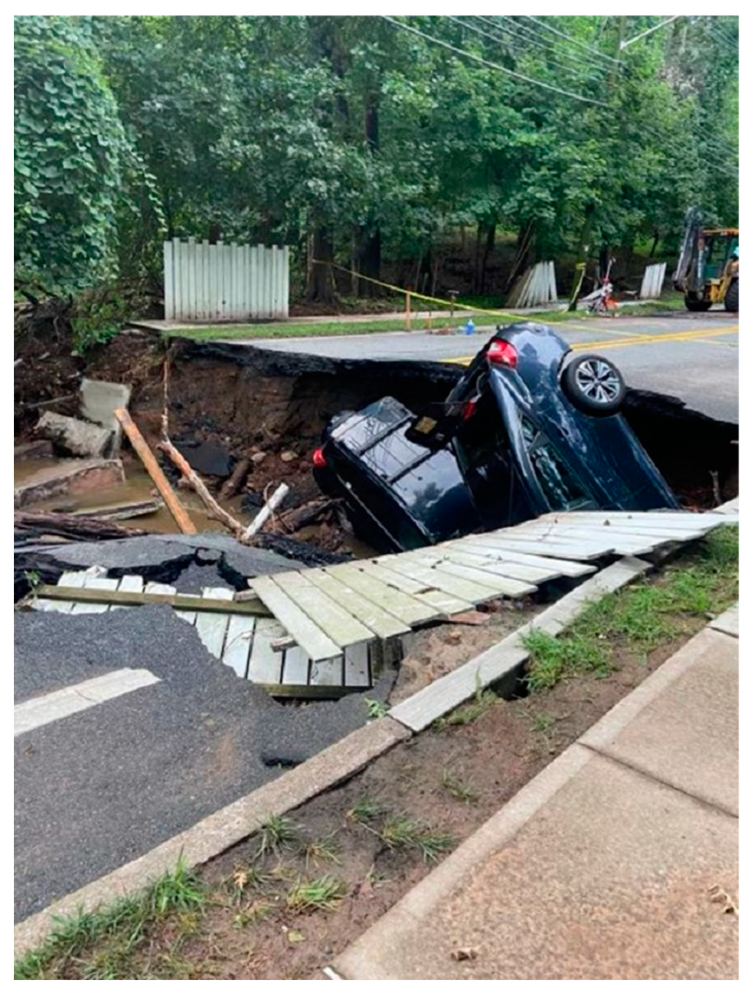
Figure 3.
Different types of hydraulic loading applications; (a) Monotonic water exfiltration (outflow), in which water supplies from the defect and drains from the top of the sample (b) Monotonic water infiltration (inflow), in which the sample is already fully saturated, and the water (rainwater) infiltrates through the defect, (c) Infiltration—exfiltration cycles where the water is supplied through the defect until it becomes fully saturated (exfiltration) and the supplied water discharges from the defect afterward (infiltration).

Figure 4.
Monotonic water infiltration hydraulic loading application with water head declination.

Figure 5.
Height of water level and the void ceiling (Hcc is the height of the existing cavity ceiling, Hmax is the maximum water level, and θ is the angle of the cavity void).
Figure 5.
Height of water level and the void ceiling (Hcc is the height of the existing cavity ceiling, Hmax is the maximum water level, and θ is the angle of the cavity void).

Figure 6.
Different shapes of studied defects; (a) radial, (b) straight, (c) rectangular, (d) circular (hole), (e) waist-shape, and (f) square.
Figure 6.
Different shapes of studied defects; (a) radial, (b) straight, (c) rectangular, (d) circular (hole), (e) waist-shape, and (f) square.
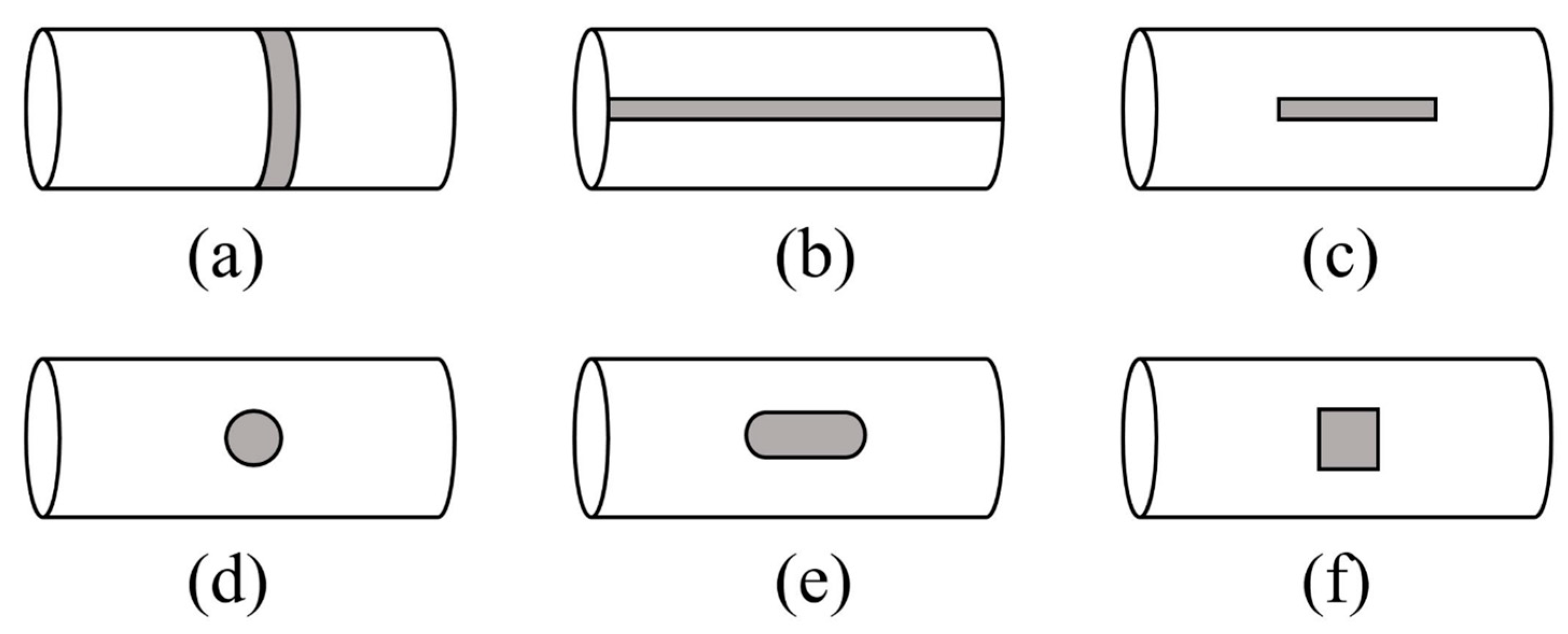
Figure 7.
Gap sand erosion phases: (a) fine washing and (b) arching.

Figure 8.
SEDP progression and sinkhole occurrence.
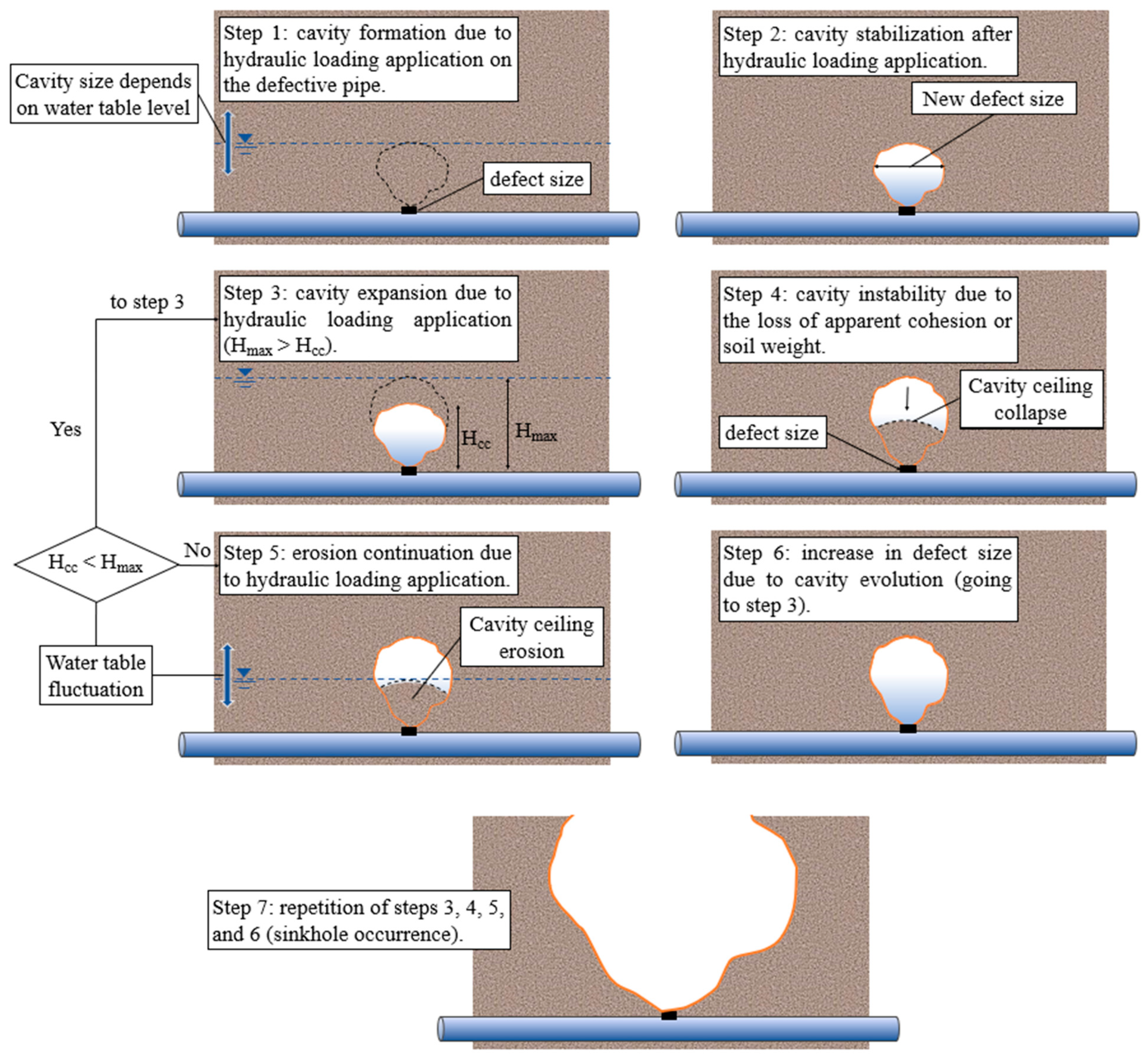
Figure 9.
Two possible extreme scenarios for SEDP occurrence. The defect is located at the (a) top, with the water table above the pipe and (b) bottom, with the water table below the pipe.
Figure 9.
Two possible extreme scenarios for SEDP occurrence. The defect is located at the (a) top, with the water table above the pipe and (b) bottom, with the water table below the pipe.
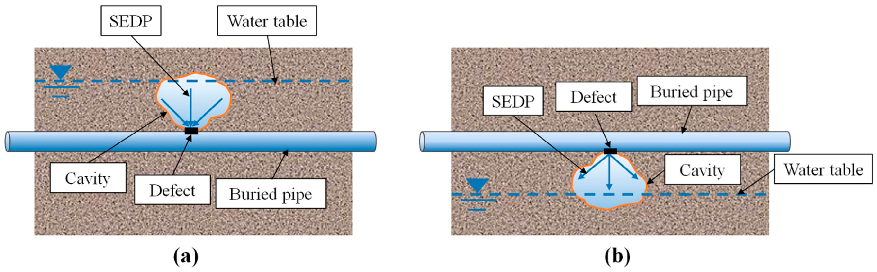

Table 1.
Summary of experimental research in SEDP.
| Researchers | Varied Parameter(s) | Test Box (mm) | Main Findings |
|---|---|---|---|
| Mukunoki et al. [24] | Defect shape; defect size; hydraulic load application 1 | Cylinder 1; 130 × 100 | Cyclic hydraulic loading causes larger ground subsidence than monotonic loading (for the same type of backfill soil). |
| Mukunoki et al. [41] | Defect size; relative density; particle size; | Cylinder; 130 × 100 | Relative density plays a crucial role in SEDP, and backfill with low relative density is more susceptible to SEDP. The ratio between mean particle size (D50) and defect size is significant when predicting the erodibility of soils. Curvature and uniformity coefficients are also important parameters when prediction soil erosion. |
| Guo et al. [42] | Particle size; water head; defect size; backfill height | Rectangular 2; 500 × 500 × 600 Cylinder; 480 × 500 | Particle and defect size had a major influence on the SEDP rate 3, while water head (hw) and backfill height (hs) had a major impact on the cavity formation geometry. |
| Sato and Kuwano [43] | Other subsurface pipe locations; soil type | Rectangular; 300 × 200 × 80 | If another subsurface pipe exists overhead the pipe with the defect, this only changes the cavity formation shape. This shape depends closely on the relative location of both pipes (the defective and the non-defective one) |
| Indiketiya et al. [44] | Hydraulic load application | Rectangular; 800 × 400 × 100 | Particles less than 0.3 mm are highly susceptible to erosion through 5 mm openings of embedment material with a maximum particle size of 4.75 mm.When the water table is below the void, the void is stable. When the water table is between the void ceiling and the defect, the void ceiling is stable; meanwhile, when the void is submerged, it becomes unstable. |
| Tang et al. [45] | Particle size; slot position; slot size; water level | Rectangular; 500 × 500 × 80 | The ratio between sand volumetric flow rate (qs) and water volumetric flow rate (qw) is linearly proportional. Also, the relationship between qs/qw and the particle-defect size ratio is exponentially proportional. |
| Karoui et al. [46] | Water head; hydraulic load application | Rectangular; 400 × 300 × 140 | They measured pore pressure near the defect and found it fluctuates as the cavity forms or expands. |
| Indiketiya et al. [47] | Soil type; slot size; hydraulic load application | Rectangular; 800 × 400 × 100 | When the backfill material is finer, the onset of cavity formation occurs faster (i.e., it happens at the earlier cycles) than with coarser backfill. |
| Kwak et al. [48] | Soil type; relative density | Rectangular; 1400 × 900 × 100 | Uniformly graded soils are more susceptible to soil erosion and sinkhole formation than non-uniformly graded soils. |
| Basak and Sarkar [49] | Water head; slot size; slot location | Rectangular; 600 × 500 × 120 | The soil erosion rate is highest when the slot (defect) is located on top of the pipe. |
| Ali and Choi [50] | Soil type; defect location; hydraulic load application | Rectangular; 700 × 600 × 330 | Developed a sinkhole/ground settlement risk index as a function of soil type, hydraulic load and defect location. However, the number of tests done was very limited. |
| Kwak et al. [51] | Hydraulic load application (rainfall intensity) | Rectangular; 1400 × 900 × 100 | Rainfall intensity dramatically impacts ground subsidence during and after rainfall and sinkhole occurrence. |
| Zhang et al. [52] | Hydraulic head; defect shape | Rectangular; 400 × 750 × 200 | In gaped graded backfill, the loss of fines is mostly seen above the defect beyond the onset region. A higher hydraulic head leads to a higher risk of collapse. |
| Khudhair et al. [53] | Soil type; water head | Rectangular; 700 × 490 × 100 | Determined two parameters strongly influenced the soil erosion process and subsidence: water head and soil type. Water pressure was directly proportional to the volume of eroded material, and clayey soil was highly susceptible to subsidence but not soil erosion. |
| Mohamed et al. [54] | Water head; defect location; defect size; soil type | Rectangular; 1500 × 750 × 1000 | The ground subsidence shape and dimensions (maximum settlement and width) depend on the defect location, size, water head, and soil type. When the soil type is finer, the ground subsidence is more pronounced. |
1 Diameter × Height. 2 Length × Height × Width. 3 SEDP rate: Water and eroded soil flow rate during the test
Table 2.
Parameters that effect SEDP pertaining to pipe condition.
| Researchers | Defect Size (mm) | Defect Shape | Defect Location | Pipe Depth 1 (mm) |
|---|---|---|---|---|
| Mukunoki et al. [24] | 5 × 5; 2.5 × 10; 5 × 50; 5 × 78.5 | Square, rectangle, straight | Top of the pipe, on the circumference of the pipe | 100 |
| Mukunoki et al. [41] | 2.1 and 5 | Straight | on the circumference of the pipe | 100 |
| Guo et al. [42] | 10 and 20 | Circular | Top of the pipe | 100, 200, 300, and 400 |
| Tang et al. [45] | 3 and 9 | Straight | Top, side and horizontal of the pipe | 250 and 300 |
| Indiketiya et al. [47] | 10 × 60; 20 × 60; 30 × 60 | Rectangle | Top of the pipe | 400 |
| Basak and Sarkar [49] | 3 and 5 | Straight | Top, side and horizontal of the pipe | 100 |
| Ali and Choi [50] | - | Artificially created crack with no particular shape or dimensions | Bottom and top | 40 |
| Zhang et al. [52] | 5 and 5 × 10 | Circular and waist-shaped | Top of the pipe | 500 |
1 pipe depth is equivalent to backfill height (hs).
Disclaimer/Publisher’s Note: The statements, opinions and data contained in all publications are solely those of the individual author(s) and contributor(s) and not of MDPI and/or the editor(s). MDPI and/or the editor(s) disclaim responsibility for any injury to people or property resulting from any ideas, methods, instructions or products referred to in the content. |
© 2023 by the authors. Licensee MDPI, Basel, Switzerland. This article is an open access article distributed under the terms and conditions of the Creative Commons Attribution (CC BY) license (https://creativecommons.org/licenses/by/4.0/).
Share and Cite
MDPI and ACS Style
Dastpak, P.; Sousa, R.L.; Dias, D. Soil Erosion Due to Defective Pipes: A Hidden Hazard Beneath Our Feet. Sustainability 2023, 15, 8931. https://doi.org/10.3390/su15118931
AMA Style
Dastpak P, Sousa RL, Dias D. Soil Erosion Due to Defective Pipes: A Hidden Hazard Beneath Our Feet. Sustainability. 2023; 15(11):8931. https://doi.org/10.3390/su15118931
Chicago/Turabian StyleDastpak, Pooya, Rita L. Sousa, and Daniel Dias. 2023. "Soil Erosion Due to Defective Pipes: A Hidden Hazard Beneath Our Feet" Sustainability 15, no. 11: 8931. https://doi.org/10.3390/su15118931
Note that from the first issue of 2016, this journal uses article numbers instead of page numbers. See further details here.