
Exploring the Effects of DEE Pilot Injection on a Biogas-Fueled HCCI Engine at Different Injection Locations
 , ,
, , 
Abstract
:1. Introduction
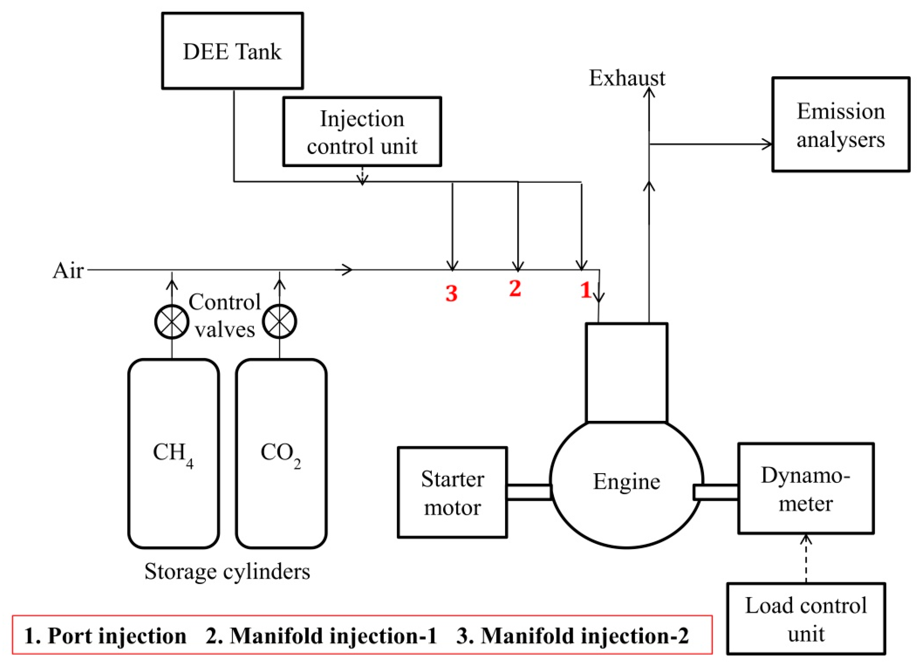
2. Experimental Setup
3. Methodology
4. Results and Discussions
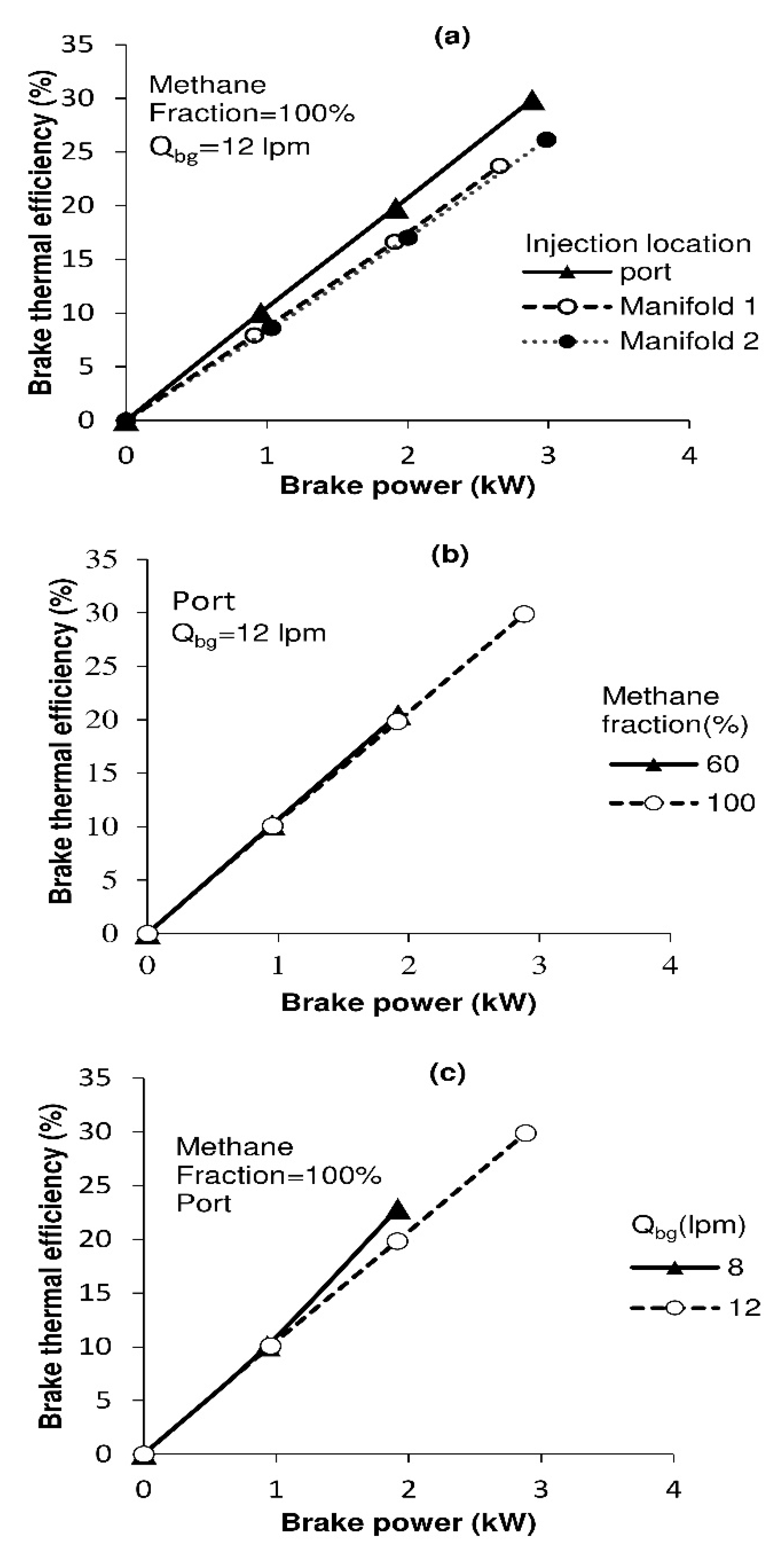
4.1. Brake Thermal Efficiency
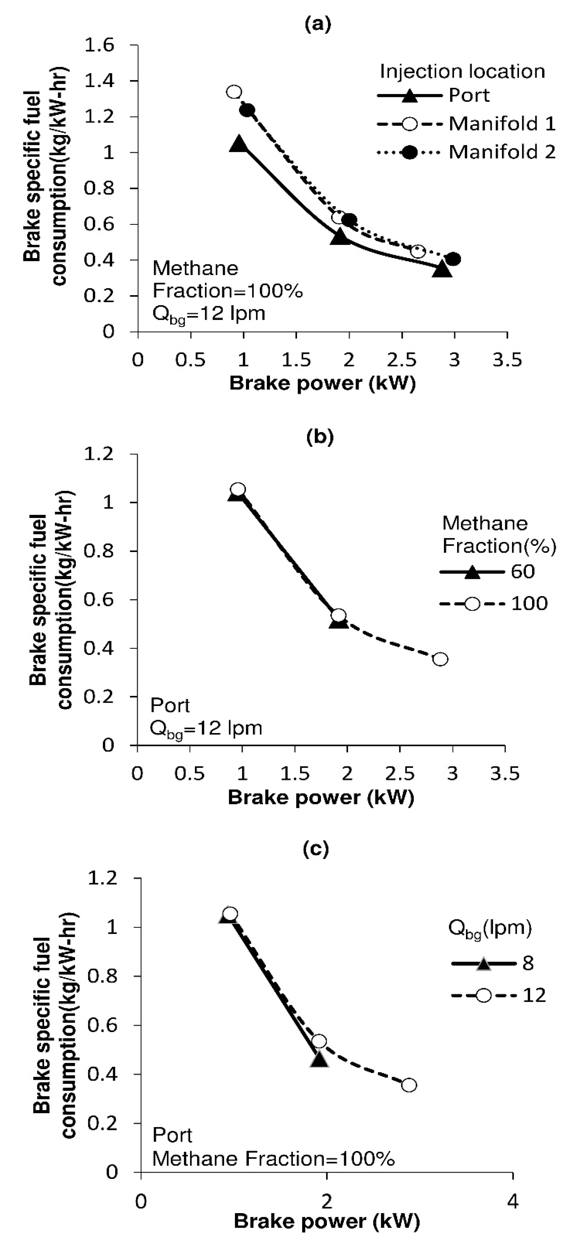
4.2. Brake Specific Fuel Consumption
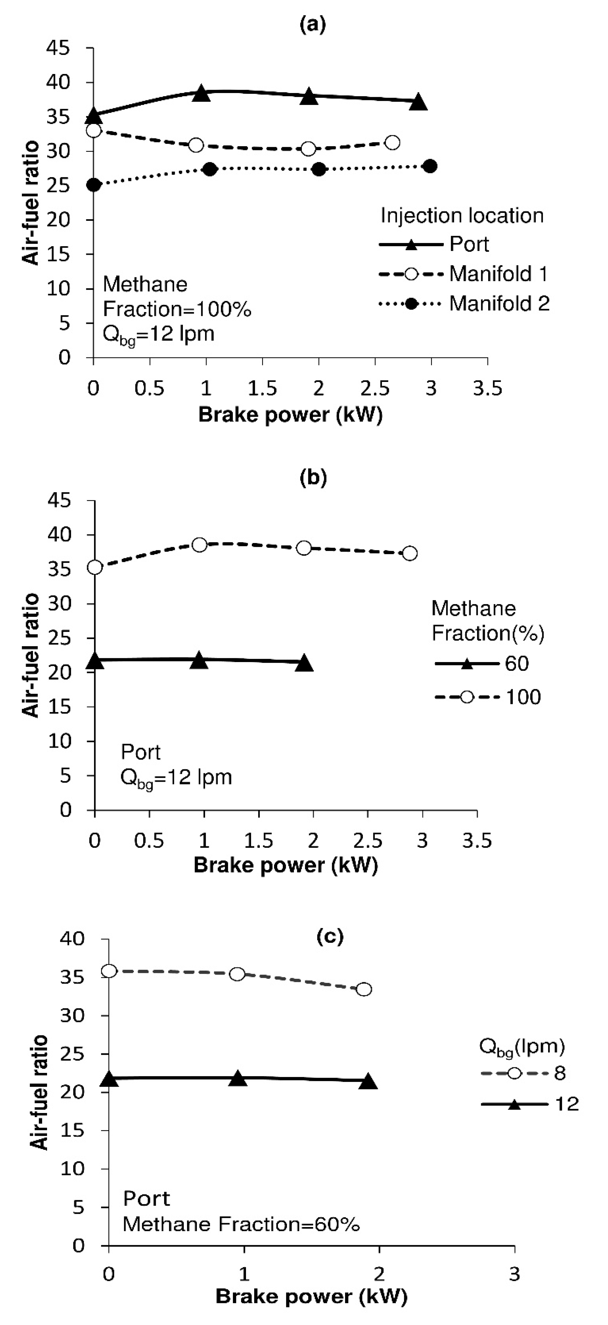
4.3. Air–Fuel Ratio
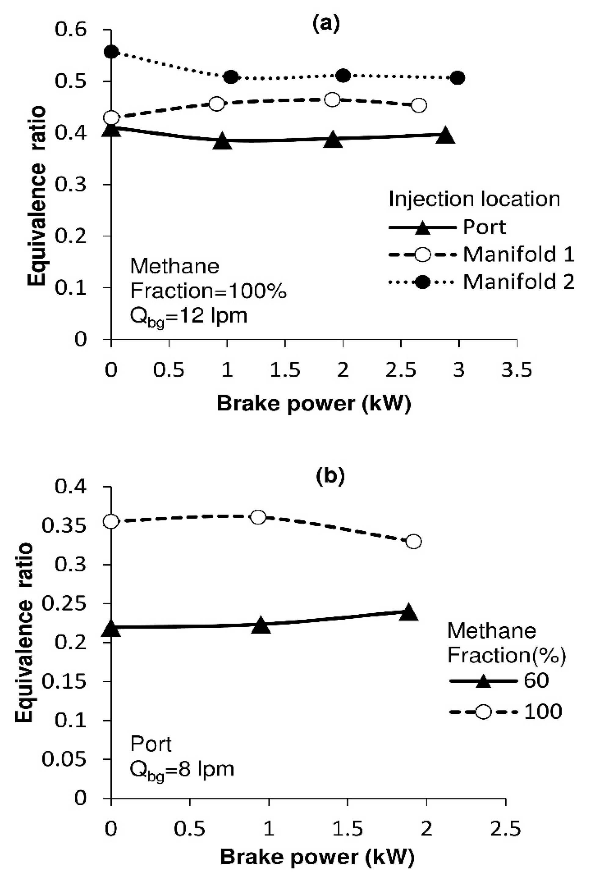
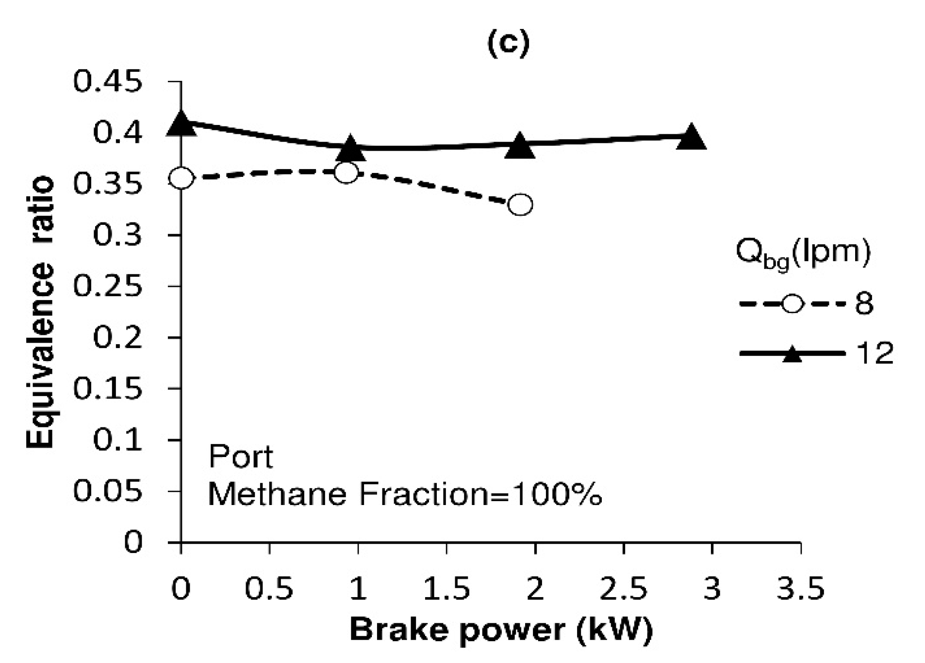
4.4. Equivalence Ratio
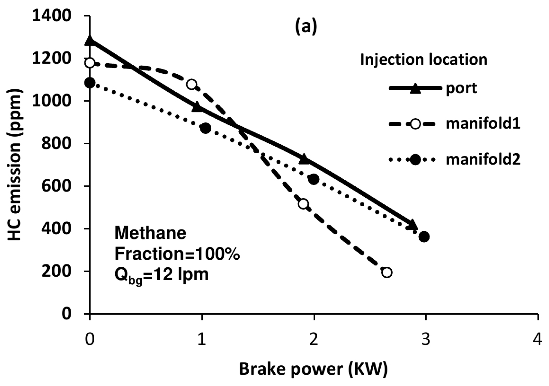
4.5. HC Emission

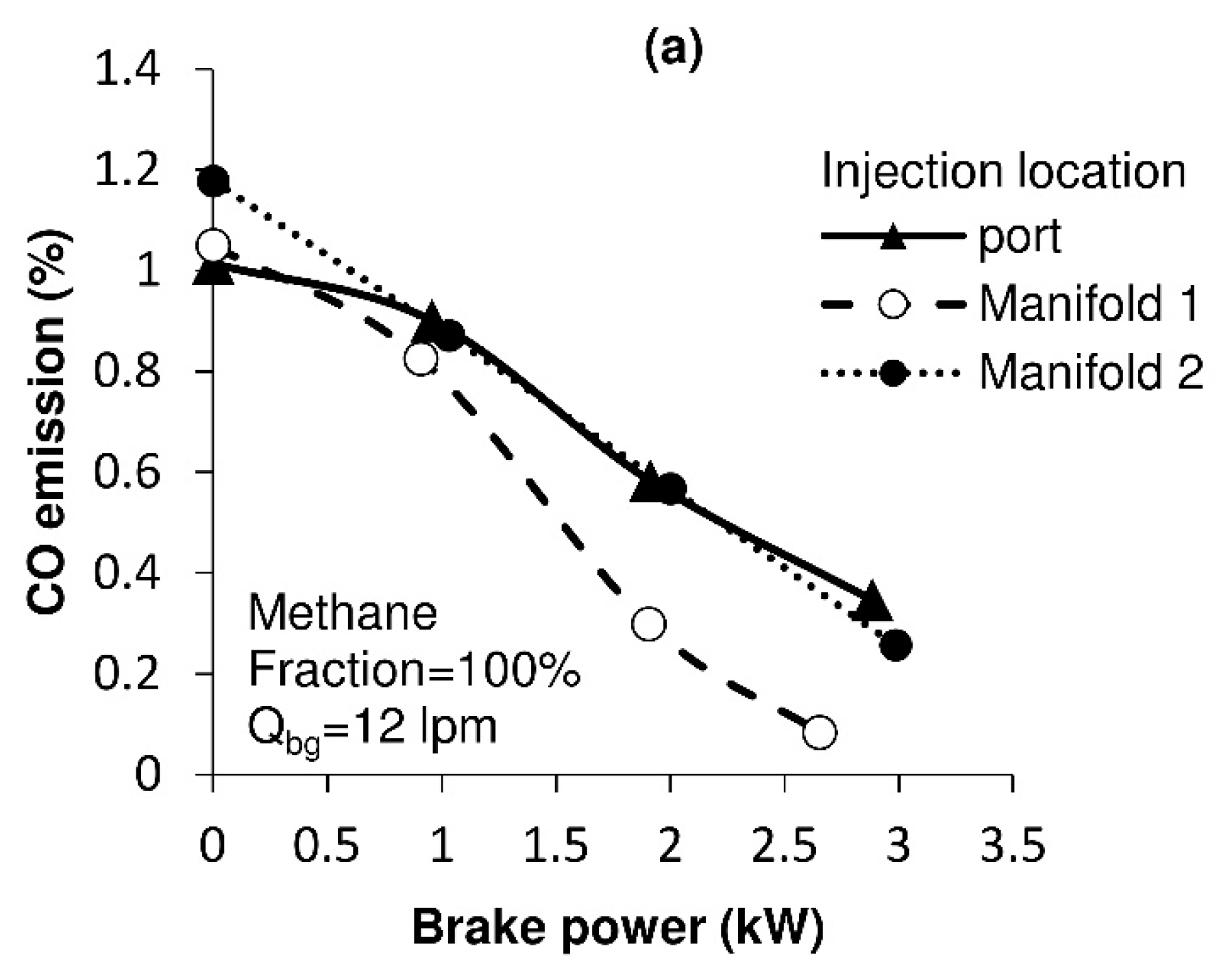
4.6. CO Emission

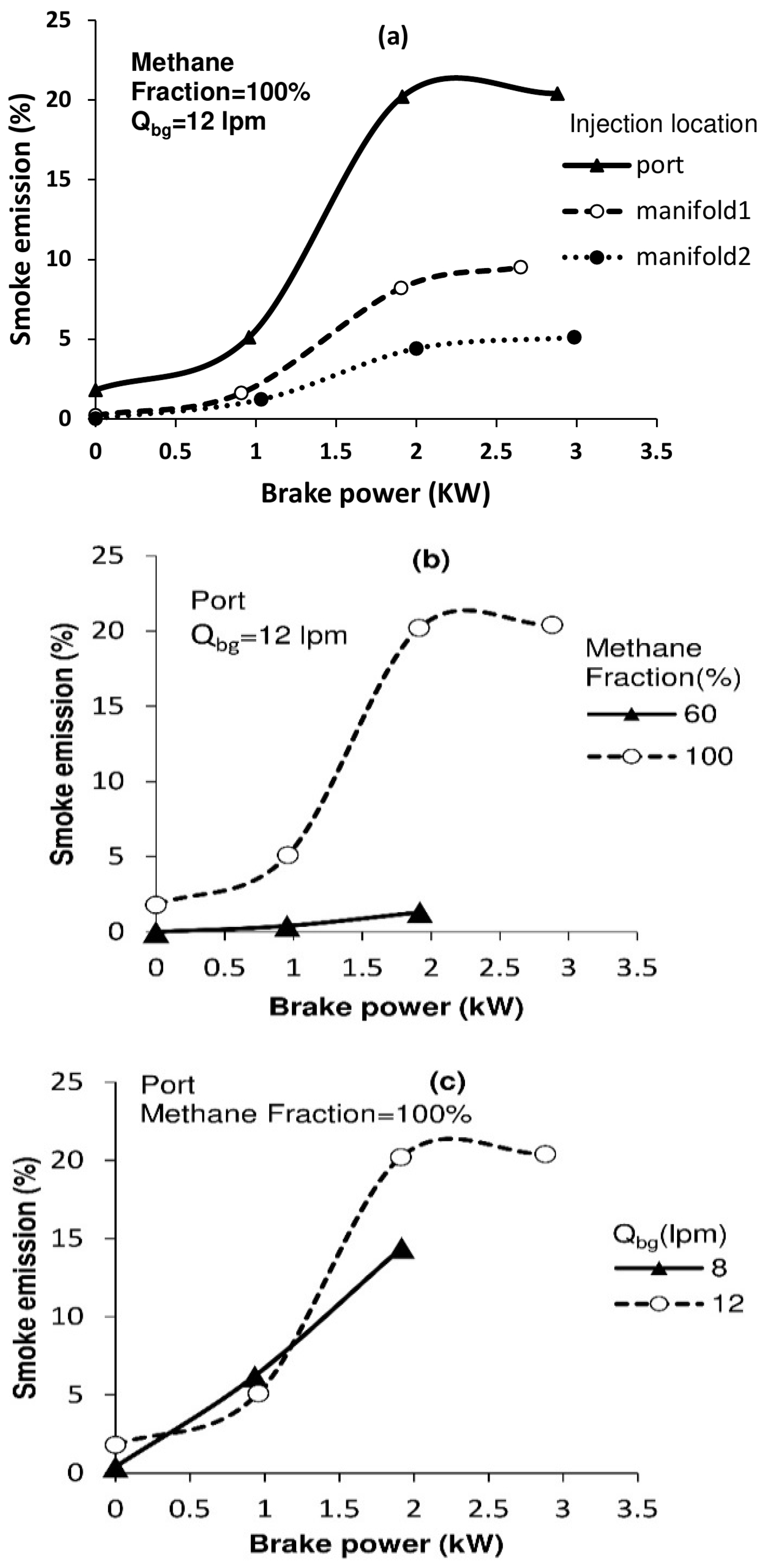
4.7. Smoke Emission
4.8. NOx Emission
5. Conclusions
- The selection of intake parameters and injection location in the DEE were crucial in achieving the desired outcomes.
- The efficient management of methane quantity and biogas flow rate was successfully achieved.
- The performance evaluation across critical levels focused on the emission characteristics of the HCCI engine.
- At 1800 rpm, port injection demonstrated superior thermal efficiency compared to manifold injections.
- Manifold injections resulted in lower emissions, including reduced smoke and NOx, compared to conventional methods.
- Increasing the biogas flow rate had the potential to enhance the maximum operating load limit by reducing knock, albeit with a slight decrease in thermal efficiency.
Author Contributions
Funding
Institutional Review Board Statement
Informed Consent Statement
Data Availability Statement
Acknowledgments
Conflicts of Interest
References
- Hennig, C.; Gawor, M. Bioenergy production and use: Comparative analysis of the economic and environmental effects. Energy Convers. Manag. 2012, 63, 130–137. [Google Scholar] [CrossRef]
- Cleetus, C.; Thomas, S.; Varghese, S. Synthesis of Petroleum-Based Fuel from Waste Plastics and Performance Analysis in a CI Engine. J. Energy 2013, 2013, 608797. [Google Scholar] [CrossRef] [Green Version]
- Huang, J.; Crookes, R.J. Assessment of simulated biogas as a fuel for the spark ignition engine. Fuel 1998, 77, 1793–1801. [Google Scholar] [CrossRef]
- Mihic, S. Biogas Fuel for Internal Combustion Engines. Ann. Fac. Eng. Hunedora 2004, 2, 12. [Google Scholar]
- Kapdi, S.; Vijay, V.; Rajesh, S.; Prasad, R. Biogas scrubbing, compression and storage: Perspective and prospectus in Indian context. Renew. Energy 2005, 30, 1195–1202. [Google Scholar] [CrossRef]
- Machrafi, H.; Cavadias, S.; Amouroux, J. A parametric study on the emissions from an HCCI alternative combustion engine resulting from the auto-ignition of primary reference fuels. Appl. Energy 2008, 85, 755–764. [Google Scholar] [CrossRef] [Green Version]
- Feroskhan, M.; Ismail, S.; Gosavi, S.; Tankhiwale, P.; Khan, Y. Optimization of performance and emissions in a biogas–diesel dual fuel engine with cerium oxide nanoparticle addition. Proc. Inst. Mech. Eng. Part D J. Automob. Eng. 2019, 233, 1178–1193. [Google Scholar] [CrossRef]
- Yao, M.; Zheng, Z.; Liu, H. Progress and recent trends in homogeneous charge compression ignition (HCCI) engines. Prog. Energy Combust. Sci. 2009, 35, 398–437. [Google Scholar] [CrossRef]
- Mohamed Ibrahim, M.; Varuna Narasimhan, J.; Ramesh, A. Comparison of the predominantly premixed charge compression ignition and the dual fuel modes of operation with biogas and diesel as fuels. Energy 2015, 89, 990–1000. [Google Scholar] [CrossRef]
- Hussaini, S.Y.; Lahane, S.; Patil, N. Analysis of Performance and Emission Characteristics of a Homogeneous Charge Compression Ignition (HCCI) Engine. Procedia Technol. 2016, 25, 854–861. [Google Scholar] [CrossRef] [Green Version]
- Feroskhan, M.S.I. A review on the purification and use of biogas in compression ignition engines. Int. J. Automot. Mech. Eng. 2017, 14, 4383–4400. [Google Scholar] [CrossRef]
- Patil, K.R.; Thipse, S.S. Experimental investigation of CI engine combustion, performance and emissions in DEE-kerosene-diesel blends of high DEE concentration. Energy Convers. Manag. 2015, 89, 396–408. [Google Scholar] [CrossRef]
- Königsson, F.; Stalhammar, P.; Angstrom, H.-E. Characterization and Potential of Dual Fuel Combustion in a Modern Diesel Engine; SAE International: Warrendale, PA, USA, 2011. [Google Scholar] [CrossRef]
- Mustafi, N.N.; Raine, R.R.; Verhelst, S. Combustion and emissions characteristics of a dual fuel engine operated on alternative gaseous fuels. Fuel 2013, 109, 669–678. [Google Scholar] [CrossRef] [Green Version]
- Intergovernmental Panel on Climate Change (IPCC). Climate Change 2013: The Physical Science Basis; Cambridge University Press: Cambridge, UK, 2013. [Google Scholar]
- Bari, S.; Liu, H.; Lim, T.H. Experimental study on biogas combustion in a homogeneous charge compression ignition engine. Appl. Energy 2016, 175, 303–311. [Google Scholar]
- Kuti, O.A.; Oyedun, A.O. Homogeneous charge compression ignition (HCCI) engine fuelled with biogas: Effect of biogas composition on engine performance and emissions. Renew. Energy 2018, 122, 129–137. [Google Scholar]
- Khandal, S.V.; Banapurmath, N.R.; Gaitonde, V.N. Performance studies on homogeneous charge compression ignition (HCCI) engine powered with alternative fuels. Renew. Energy 2019, 132, 683–693. [Google Scholar] [CrossRef]
- Guo, T.; Duan, X.; Liu, Y.; Liu, J.; Zhou, X.; Li, Y.; Lai, M.-C.; Guo, G. A comparative experimental study on emission characteristics of a turbocharged gasoline direct-injection (TGDI) engine fuelled with gasoline/ethanol blends under transient cold-start and steady-state conditions. Fuel 2021, 277, 118153. [Google Scholar] [CrossRef]
- Duan, X.; Lai, M.-C.; Jansons, M.; Guo, G.; Liu, J. A review of controlling strategies of the ignition timing and combustion phase in homogeneous charge compression ignition (HCCI) engine. Fuel 2020, 285, 119142. [Google Scholar] [CrossRef]
- Harari, P.A.; Banapurmath, N.R.; Yaliwal, V.S.; Khan, T.M.Y.; Badruddin, I.A.; Kamangar, S.; Mahlia, T.M.I. Effect of Injection Timing and Injection Duration of Manifold Injected Fuels in Reactivity Controlled Compression Ignition Engine Operated with Renewable Fuels. Energies 2021, 14, 4621. [Google Scholar] [CrossRef]
- TTeoh, Y.H.; Huspi, H.A.; How, H.G.; Sher, F.; Din, Z.U.; Le, T.D.; Nguyen, H.T. Effect of Intake Air Temperature and Premixed Ratio on Combustion and Exhaust Emissions in a Partial HCCI-DI Diesel Engine. Sustainability 2021, 13, 8593. [Google Scholar] [CrossRef]
- Wu, G.; Ge, J.C.; Kim, M.S.; Choi, N.J. NOx–Smoke Trade-off Characteristics in a Palm Oil-Fueled CRDI Diesel Engine under Various Injection Pressures and EGR Rates. Appl. Sci. 2022, 12, 1069. [Google Scholar] [CrossRef]
- Feroskhan, M.; Thangavel, V.; Subramanian, B.; Sankaralingam, R.K.; Ismail, S.; Chaudhary, A. Effects of operating parameters on the performance, emission and combustion indices of a biogas fuelled HCCI engine. Fuel 2021, 298, 120799. [Google Scholar] [CrossRef]
- Chen, Z.; Yao, M.; Zheng, Z.; Zhang, Q. Experimental and Numerical Study of Methanol/Dimethyl Ether Dual-Fuel Compound Combustion. Energy Fuels 2009, 23, 2719–2730. [Google Scholar] [CrossRef]
- Lee, K.; Cho, S.; Kim, N.; Min, K. A study on combustion control and operating range expansion of gasoline HCCI. Energy 2015, 91, 1038–1048. [Google Scholar] [CrossRef]
- Lounici, M.S.; Loubar, K.; Tazerout, M.; Balistrou, M.; Tarabet, L. Experimental Investigation on the Performance and Exhaust Emission of Biogas-Diesel Dual-Fuel Combustion in a CI Engine; SAE Technical Paper; SAE International: Warrendale, PA, USA, 2014. [Google Scholar] [CrossRef]
- Feroskhan, M.; Ismail, S.; Panchal, S.H. Study of methane enrichment in a biogas fuelled HCCI engine. Int. J. Hydrogen Energy 2022, 47, 3504–3514. [Google Scholar] [CrossRef]
- Feroskhan, M.; Ismail, S.; Natarajan, G.; Manavalla, S.; Khan, T.M.Y.; Khadar, S.D.A.; Ali, M.A. A Comprehensive Study of the Effects of Various Operating Parameters on a Biogas-Diesel Dual Fuel Engine. Sustainability 2023, 15, 1232. [Google Scholar] [CrossRef]

| Intake Condition | Level 1 | Level 2 | Level 3 | Level 4 |
|---|---|---|---|---|
| Injection position | Port | Manifold1 | Manifold2 | - |
| Biogas flow rate (lpm) | 8 | 12 | - | - |
| Methane fraction (%) | 60 | 100 | - | - |
| Torque (N.m) | 5 | 10 | 15 | 20 |
| Quantity Measured | Measuring Device |
|---|---|
| Flow rate of CH4 | Thermal mass flow meter |
| Flow rate of CO2 | Thermal mass flow meter |
| Torque | Eddy current dynamometer |
| Flow rate of neat diesel | Burette |
| Air flow rate | Orifice meter |
| Smoke emissions | AVL 437C smoke meter |
| CO emission | AVL 444N gas analyser |
| HC emissions | |
| NOx emissions |
| Output Parameter | Uncertainty (±) |
|---|---|
| CO emission | 3% |
| HC emissions | 3% |
| Brake thermal efficiency | 2.46% |
| Diesel consumption | 1% |
| Smoke emissions | 1% |
| NOx emissions | 1% |
| Engine Mode | HC Emission (ppm) | CO Emission (%) | NOx Emission (ppm) | Smoke Emission (%) |
|---|---|---|---|---|
| Diesel-only | 50–100 | 0.08–0.16 | 36–929 | 32–60 |
| Dual fuel (8 lpm of biogas with 100% methane) | 235–449 | 0.14–0.22 | 42–760 | 22–40 |
| HCCI (8 lpm of biogas with 100% methane) | 200–850 | 0.2–1.4 | 0–5 | 0–22 |
Disclaimer/Publisher’s Note: The statements, opinions and data contained in all publications are solely those of the individual author(s) and contributor(s) and not of MDPI and/or the editor(s). MDPI and/or the editor(s) disclaim responsibility for any injury to people or property resulting from any ideas, methods, instructions or products referred to in the content. |
© 2023 by the authors. Licensee MDPI, Basel, Switzerland. This article is an open access article distributed under the terms and conditions of the Creative Commons Attribution (CC BY) license (https://creativecommons.org/licenses/by/4.0/).
Share and Cite
Mishra, N.; Mitra, S.; Thapliyal, A.; Mahajan, A.; Khan, T.M.Y.; Manavalla, S.; Baig, R.U.; Janvekar, A.A.; M, F. Exploring the Effects of DEE Pilot Injection on a Biogas-Fueled HCCI Engine at Different Injection Locations. Sustainability 2023, 15, 10713. https://doi.org/10.3390/su151310713
Mishra N, Mitra S, Thapliyal A, Mahajan A, Khan TMY, Manavalla S, Baig RU, Janvekar AA, M F. Exploring the Effects of DEE Pilot Injection on a Biogas-Fueled HCCI Engine at Different Injection Locations. Sustainability. 2023; 15(13):10713. https://doi.org/10.3390/su151310713
Chicago/Turabian StyleMishra, Nihal, Shubham Mitra, Abhishek Thapliyal, Aniket Mahajan, T. M. Yunus Khan, Sreekanth Manavalla, Rahmath Ulla Baig, Ayub Ahmed Janvekar, and Feroskhan M. 2023. "Exploring the Effects of DEE Pilot Injection on a Biogas-Fueled HCCI Engine at Different Injection Locations" Sustainability 15, no. 13: 10713. https://doi.org/10.3390/su151310713