
Analysis and Comparison of Daylighting Technologies: Light Pipe, Optical Fiber, and Heliostat

1
Institute of Energy Power Innovation, North China Electric Power University, Beijing 102206, China
2
School of New Energy, North China Electric Power University, Beijing 102206, China
*
Author to whom correspondence should be addressed.
Sustainability 2023, 15(14), 11044; https://doi.org/10.3390/su151411044
Submission received: 30 May 2023
/
Revised: 12 July 2023
/
Accepted: 12 July 2023
/
Published: 14 July 2023
(This article belongs to the Special Issue Collective Wisdom in the Solar Energy and Storage Sector - 2nd Edition)
Abstract
:This article analyzes and compares three daylighting technologies: light pipes, optical fibers, and heliostats. This work aims to evaluate their efficiency, sustainability, and cost-effectiveness in providing natural light to indoor spaces. The analysis includes a review of the principles behind each technology, the design and development of the prototypes and experiments carried out by our research team, their advantages and disadvantages, and their applications in different settings. The comparison is based on several criteria, such as installation, cost, efficiency, output spectrum, and hybrid system. The results indicate that each technology has its unique features and is suited to specific applications. Light pipes are effective for short distances, and they can be easily integrated into existing buildings. Optical fibers are suitable for long distances and offer flexibility in design, but they require more maintenance. Heliostats are ideal for large spaces, but they are expensive to install and operate. Overall, this study provides valuable insight into the strengths and weaknesses of three daylighting technologies and helps designers and architects make informed decisions when selecting the most appropriate solution for future work.

1. Introduction
In a world where carbon emissions, global warming, and sustainable design are increasingly in focus, natural lighting planning in non-residential buildings has become an important strategy for improving energy efficiency by minimizing artificial lighting, heating, and cooling loads. Innovative daylighting approaches and systems can greatly reduce buildings’ electricity consumption and improve indoor lighting quality [1]. Therefore, daylight can have a significant impact on energy efficiency, comfort for the occupants, indoor air quality, and greenhouse gas emissions.
Thus, daylighting uses natural light to illuminate indoor spaces, and it is an important tool in architectural design [2,3,4,5]. However, artificial lighting consumes 20–30% of the total energy consumption of commercial buildings, accounting for one-third of the total electricity load of traditional office buildings [6,7,8]. Consequently, the daylighting system is a design approach that aims to optimize the use of daylight in buildings, reducing the need for artificial lighting and saving energy. Daylighting can save energy for lighting up to about 63% for user input setup and 68% for automated setup [9].
Until the 1940s, daylight was the main source of light for buildings, and it was supplemented by artificial lighting [10]. In just two decades, artificial lighting transformed the workplace by meeting the lighting requirements of most users. However, the energy crisis and environmental problems of the 1970s led to a search for a new lighting method, and with the growing interest of architects and building owners, daylighting became a new aspect of the design of architectural lighting. Daylighting is often integrated into buildings as an architectural claim and energy-saving feature [10]. Moreover, the current interest in daylight goes beyond the energy efficiency issues of the past decades and becomes more occupant-centric to meet the needs of occupants for comfort and health [11,12,13]. Accordingly, the purpose of space lighting is not only to adequately illuminate the visual mission and save electricity but also to create an attractive visual environment. In addition to economic benefits, the spectrum of sunlight obtained from indoor daylight [14] is also more beneficial to human health than artificial lighting [15,16,17].
As widely reported in [1,18], daylighting has always been included in the design of buildings by adding holes of different shapes to the walls, the decorative re-bending of surfaces on the walls, improved window designs, etc. Architectural structures, such as French windows [19] and skylights [20,21,22], bring sunlight directly into the building. Light shelves [23] and a prismatic glass window [24] also redirect sunlight to the ceiling, providing indirect illumination and reducing glare. However, the interaction between ceiling shape and louvers has an impact on daylighting performance [25]. Building structural markings also affect daylighting [26]. All of these designs are specific to the structure of the building, and they cannot be easily generalized to a wider range of applications in residential or commercial buildings. Each of these technologies has its advantages and disadvantages, and the most effective solution will depend on factors such as the location, orientation, and design of the building.
In recent decades, a sustainable and cost-effective daylighting system has emerged in building lighting; it uses natural light to illuminate interior spaces deep in buildings and where traditional windows are not suitable for providing sufficiently uniform lighting [27]. However, the amount and quality of daylight entering a building can be affected by various factors, such as building orientation, shading, and weather conditions [28]. Therefore, daylight transport technologies have been developed to optimize the distribution of natural light in buildings, improving the eye’s visual comfort and the interior’s energy efficiency [29]. These devices and systems include light pipes, optical fibers, and heliostats, which guide natural light to windowless or remote buildings and control lighting to maximize the use of available sunlight [30]. Hence, the analyses and comparisons of daylighting technologies, such as light pipes, optical fibers, and heliostats, are essential in determining their suitability for specific applications based on features such as cost, design flexibility, installation and maintenance requirements, and performance.
Therefore, this study aims to analyze and compare three innovative daylighting technologies, such as light pipes, optical fibers, and heliostats, based on their principles, advantages, limitations, and potential applications. This is necessary to determine the most effective and efficient way to provide sufficient natural light in buildings while minimizing energy consumption and costs. Furthermore, factors such as their transmission efficiency, cost-effectiveness, ease of installation and maintenance, and impact on indoor air quality are considered for the comparison. Finally, each of these three daylighting technologies has its advantages and disadvantages in terms of performance, cost, installation requirements, and potential application areas. Light pipes are cost-effective and efficient over short distances, and easy to install. Optical fiber is considered the most flexible and efficient daylight transport technology because it can bend around corners and obstacles, as well as transmit light over long distances with minimal loss. Heliostats provide high-level natural light throughout the day and are effective for large-scale buildings.
2. Daylighting Technologies
Advanced daylighting systems currently available in the building industry are divided into shaded and unshaded daylighting systems [1]. The presence of shadows affects the energy balance and the user’s visual comfort. Therefore, the appropriate shading system must be chosen to limit undesired solar gain while meeting adequate daylight and aesthetic requirements [31]. The conventional side or top light system also directs natural light that penetrates the interior of a building to maximize the level of natural light within the building and optimize the quality of light for the occupants in the environment [32,33,34]. Traditional daylighting technology has mostly been improved by the employment of new optical materials, parts, and gadgets, including overhangs, lighting boxes, louvers, blinds, screens, and light filters [29].
Daylighting systems designed without shading are mainly used to redirect sunlight to areas far away from windows or skylights and are the ones in which daylight transmission systems are used. This innovative daylighting system not only collects and transports sunlight over long distances deep inside the building, through fiber optics, light pipes [35], and heliostats, but also controls glare. Even though conventional and advanced daylighting systems have been discussed by different scholars [1,36,37,38,39,40], daylight transport technologies need to be further studied to become competent enough with artificial lighting.
The features of different innovative daylighting systems can include solar tracking, concentration techniques, and a daylight transport channel, although the performance of these systems is substantially different in terms of sunlight collection, transmission distance, cost, and ease of installation. These characteristics determine the location of the application for each daylight technology. Therefore, some innovative daylighting system research results using light pipes, optical fiber, and heliostat are summarized as shown in Table 1.
2.1. Light Pipe
A light pipe is an optical device that is used to transport sunlight from the roof of a building to the interior space through total internal reflection, as shown in Figure 1c. The reflectivity of the light pipe is typically between 85 and 94%, and it is composed of a highly reflective material such as aluminum or silver. The light pipe daylighting system consists of a light collector, a light pipe, and a luminaire to capture sunlight from the top roof and transport it to the entire building, as shown in Figure 1a,b [41,42,80,81]. To avoid glare and overheating, the amount of light entering the room is carefully adjusted. The SPIC 300 spectrometer was used to measure the output spectrum of a light pipe, and it shows that light pipes transmit a broad spectrum of light, including visible light and near-infrared radiation.
Thus, the light pipe-based daylighting system is ideal for rooms without windows or where traditional skylights are not feasible.
Although the internal surface of the pipe is usually made of a highly reflective material, such as glass or acrylic, the internal illuminance of the light pipe depends on its length, diameter, and angle of bending of incidence light [83], as shown in Figure 1c and Figure 2. When the bending angle increased, the average internal illuminance decreased. Hence, to easily describe the impact of sun position on the efficiency of the light pipe, the angles of incidence—15°, 45°, and 90°—are considered in our work, as shown in Figure 3. As a result, the highest average internal illumination is efficiently achieved by a zero-degree light pipe (straight light pipe) when the incidence light is parallel to the light pipe (perpendicular to the light pipe dome).
For all angles below 60°, a specular light pipe is combined with a laser-cut light deflection panel to improve illumination [85]. As a result, laser-cut panels increase the transmittance and improve the daylight autonomy of spaces equipped with horizontal light pipes [86]. Light pipe performance in summer, at a low to mid-latitude in a sunny climate, delivers a high degree of daylight [87], while a special design is required to capture low-angle daylight at a high latitude [88]. According to the actual Sun trajectory, as shown in Figure 2, the sunlight irradiation angles in the morning and at noon were selected as the illumination incidence angles, and the sunlight incidence angles were 15°, 45°, and 90°, respectively. The light source in Trace Pro selects the grid light source, while the light density distribution is uniform and the angular distribution profile selects the sunlight distribution. The irradiance on the plane, where the sun shines vertically at noon, is set to be 1000 W/m2, the irradiance is 600 W/m2 when the sun incidence angle is 45° in the morning, and the irradiance is 400 W/m2 when the sun incidence angle is 15° in the morning. The amount of irradiance transferred to the indoor space obtained from the Trace Pro simulation result is described in Table 2. Therefore, the influence of pipe length and incident angle on the transmission efficiency of the light pipe was calculated, in percentage, as the ratio of maximum average internal illuminance to external illuminance. The light transmission efficiency value at the incident angles of the sun (15°, 45°, and 90°) and the pipe lengths (500 mm, 700 mm, and 2000 mm) was given in Table 3.
The efficiency of the light pipe is calculated, in percentage, as the ratio of maximum average internal illuminance to external illuminance, as shown in Equation (1). The internal illuminance has a similar tendency for all light pipes, which is higher in the midday and low in the early morning and late afternoon, as shown in Table 3 and Figure 4. Maximum internal illumination can be achieved when the sun angle aligns with the angle of the light pipe [83].
A double light pipe was considered to efficiently transport daylight to underground areas, particularly in large rooms of the plant area, such as showrooms or museums [45]. Following the modification of the collection and transport sections, double light pipes are composed of two concentric pipes, and except for the outer surfaces covered by the same multilayer film used on the interior surfaces, the inner surfaces are similar to conventional light pipes, and they exhibit high reflection factors. There is a cavity between the two pipes. The external pipe is made of transparent materials, such as polycarbonate, and allows light to enter the intermediate room through the system. Double light pipes adopt larger collectors than traditional light pipes to transport daylight both in the inner pipe and the interior and exterior cavities.
The light pipe can be fully integrated as a piece of furniture or as an architectural structure. In addition, the light pipe was combined with large heliostats to increase the amount of daylight collected, which might be limited by the diameter of its dome [89]. Fresnel lenses can be added to further extend the sunlight transmission distance. The sunlight reflected by the heliostat is further concentrated and projected into the light pipes. In this way, more light can be captured using small light pipes [47,48,49].
The light pipe-based daylighting system designed by [50] used heliostats, and its light path was designed using mirrors. Sunlight is reflected by the heliostats and mirrors coupled into the light pipes. This combination of heliostats and light pipes extends the penetration capacity of a daylighting system. A hybrid light pipe daylighting system with an artificial lighting system [49] that allows an appropriate illumination of the targeted space and is also cheap in their maintenance is applied, as there are only a few installed lamps. However, an intelligent control system with indoor photocells is used to ensure sufficient artificial lighting is fed through the light pipes, together, with daylight.
The light pipe has a simple structure and limited transmission distance due to reflection loss. Therefore, the lengths of the pipes—500 mm, 700 mm, and 2000 mm—are considered to evaluate the effect of the length of the pipe on the efficiency of light pipes using TracePro Expert 7.0.3, as described in Table 3 and as can be seen in Figure 4. The transmission efficiency of light pipes decreases with increasing pipe length. As a result, most of the light pipes transport daylight for a distance of less than 10 m [28,90]. During the light pipe installation, a hole must be drilled in the wall structure. However, building codes and regulations prohibit drilling large holes (0.5–1 m for light pipes) in existing buildings, which suppresses the widespread application of light pipes. Light pipes also have minimal heat gain or loss, and they do not cause glare. However, they require regular cleaning to maintain their performance. As a result, researchers have developed daylighting systems that use optical fibers.
2.2. Optical Fiber
2.2.1. Concept
In daylighting applications, fiber optics are used to transmit natural light from light sources outside buildings to interior spaces that need to be illuminated [91]. Fiber optics are usually bundled in cables and connected to a roof-mounted collector that captures sunlight and directs it to the end of the optical fiber. The fiber then transmits the light to a diffuser or luminaire located within the building, where it is evenly distributed throughout the space. Optical fibers can transmit light over long distances without a significant loss of intensity or quality. This allows the design of the building to have deep floor plans or interior spaces that would otherwise be difficult to illuminate with traditional windows. In addition, because fiber optics can bypass obstacles and tight spaces, they provide greater flexibility in building design while reducing glare and heat gain. These features allow fiber-based daylighting systems to flourish [52]. Therefore, fiber optic daylighting systems are more efficient than typical artificial lighting systems in delivering daytime light, bringing benefits to users in both visual and non-visual aspects [92,93].
As introduced in [94], different shapes of optical fiber tips, aligned together with solar concentrators of different geometries, are improved, and the basic properties of sunlight capture, channeling, and scattering are also improved. However, optical fibers are expensive, and the quantity required can be reduced by installing concentrating devices to supply highly concentrated flux to the fiber entrance.
The optical fiber is the core of the dielectric material, and its refractive index is greater than that of the surrounding cladding material, resulting in the total internal reflection (TIR) of light entering the fiber end, as shown in Figure 5. The optical fibers can transmit the collected daylight remotely based on the TIR principle. Transparent cladding materials are used to improve transmission efficiency by capturing defects in the material or through other factors that scatter light from the fiber core [95].
An optical fiber is a light guide governed by Snell’s Law, which defines the passage from a medium of refractive index n1 to a medium of refractive index n2 by a light ray having an angle of incidence θ1 and angle of refraction ;
There are different types of optical fibers used in daylighting applications, such as silica, plastic, quartz, glass, liquid, and polymer optical fibers. The most common optical fibers are plastic optical fiber (POF) and silica optical fiber (SOF). Silica optical fibers were used to reduce the heat problem, which was one of the main problems in optical fiber daylighting systems. Due to its higher absorption for UV and IR radiation, the SOF of silica glass behaves opaquely for the wavelength range of UV (shorter than 200 nm) and IR (3.5–4.0 m), and its transmittance for IR radiation decreases significantly in the range of near to far IR [56]. Therefore, silica optical fiber has lower optical losses than plastic optical fiber.
There is a critical angle called the maximum acceptance angle of fibers θ1. Due to the fibers’ axial symmetry, this, in turn, defines an acceptance cone [57]. Rays with an incident angle in the air less than θ1 can realize TIR, as shown in Figure 6a. For angles greater than this limit, the complete reflection at the interface fiber cladding cannot take place, and significant losses occur due to refraction, as shown in Figure 6b. These light rays will not be internally reflected, thus eventually losing to radiation (at the cladding–jacket interface). Light rays will be confined inside the fiber core if it is input-coupled at the fiber core end-face within the acceptance angle θ1.
However, the cost-effectiveness of daylighting systems is achieved by using plastic optical fibers, which reduce system efficiency by 10–15%. To obtain the desired concentration level of light at the entrance of optical fiber bundles, the number of optical fibers must be carefully chosen by considering the size of the concentrator [56]. Thus, the numerical aperture, NA, determines the maximum acceptance angle of the optical fiber when total internal reflection occurs , as given in Equation (3).
where and are the refractive indices of the core and cladding, respectively.
2.2.2. Primary Concentrator
The primary concentrator array currently used in daylighting applications can be constructed from different types of point focus concentrators, such as a fly-eye lens array, Fresnel lenses, compound parabolic concentrators, diffractive concentrators, and combinations of lenses and mirrors. Each has advantages and disadvantages in its concentration capacity, weight, and aperture. However, conventional lenses and high-reflective mirrors are not recommended as primary concentrators for optical fiber daylighting systems due to their high cost and quality degradation.
As described in [96], a Fresnel lens-based daylight system using optic fibers has become the best choice for concentrating solar energy applications due to its advantages, such as low volume, low cost, mass production, and effective increase in energy density. Although the lens focuses light on small areas, the image is not sharp, and only visible light is inserted into the fiber. The system uses a hybrid tracking algorithm based on a photosensitive sensor and an astronomical global system positioning (GPS) algorithm, and it completes the solar tracking and positioning process by using two-axis rotation platforms, as shown in Figure 7.
Among the disadvantages of high-concentration Fresnel lenses, one is that solar spectrum dispersion decreases optical efficiency and system concentration ratios. However, we have constructed the large Fresnel lens concentrator and tested it [96], which can collect and transmit much more sunlight than a larger lens. To increase the focal point and improve uniform flux distribution, a homogenizer was considered at the fiber entrance, as shown in Figure 8a,b [96]. Its inner mirrors reflect the incident rays and change the ray path, allowing the flux shape and density distribution to be modified. The combination of the infrared filter and the homogenizer ensured that the optical fiber bundle was stable for highly concentrated sunlight transmission and that it achieved a uniform flux distribution, as shown in Figure 9.
The Fresnel lens performed better than the parabolic concentrator in collecting solar energy for indoor illumination, due to the photometric and structural simplicity of its operation [66,97]. However, according to the principles of optics, parabolic mirrors possess the best-concentrating properties due to the absence of astigmatic aberration, chromatic dispersion, and the lightest weight under the same aperture [63,98]. The Fresnel lens concentrator and a liquid fiber were also used to build a daylighting system that mixes sunlight with artificial lighting for energy-saving purposes [67].
The convex lenses have developed as the concentrators for optical fiber daylighting systems, and the Plano–convex lenses are more precise in concentration, but they are heavier than a Fresnel lens. This means a Plano-convex lens is an appropriate concentrator to concentrate sunlight with high flux density, and uniform illumination was achieved over the fiber bundle, as shown in Figure 9. As a result, most commercial daylighting systems use convex lenses as concentrators due to their reasonable cost and satisfactory concentration capacity. When compared to other parabolic reflector methods, the convex lens reduced the shadow on the fiber bundle and increased the illuminance value [99].
In research on dish-based daylighting systems via optical fibers, the design of the optical path has attracted much attention. A typical dish-based fiber daylighting system, which mainly consists of a parabolic dish concentrator, a secondary reflecting mirror (a flat mirror), a homogenizer, and optical fibers, was designed to adopt a convex mirror to reduce the attenuation of the optical fibers while the incident angle is reduced. The optical path is optimized by using a convex mirror as the second reflector to direct collimated light rays to the optical fiber [58,59], and the light is also concentrated in a small area using a concave parabolic reflector.
In the concentration process, the path of the rays is dominated by the shape of the sun. Therefore, a detailed analysis should consider the real sun’s shape, including the view angle and the brightness profile of the solar disc [100,101,102,103]. The sunlight is not parallel, but it is reflected with a view angle of 0.53°, so the second convex mirror and optical element cannot produce ideal parallel rays. The collimation effect is limited by the conservation laws of optical extension [104,105].
2.2.3. Secondary Optical Element
An optical fiber-based daylighting system requires precise solar tracking. However, solar tracking error is unavoidable in practice, and it can be caused by errors in the solar position sensor, misalignment of the axis between the lens and the optical fibers, and transmission errors [106]. Therefore, a second optical element can be added. As a result, optical elements with geometric structures can improve the acceptance angle, concentration capacity, and uniformity of concentrated flux at the same time [61,107]. The secondary lens couples light into the fiber-optic cable, increasing the acceptance angle at low tracking accuracy and improving the uniform flux distribution [54,55]. Therefore, providing uniform illumination to the fiber is essential for improving the efficiency of the daylighting system.
Ullah et al. [56] designed different secondary optical elements for flux homogenization and achieved a more uniform distribution of illumination onto the bundle of optical fibers. The optical efficiency of the secondary optics can reach 93%, and the system allows for an acceptance angle of up to 1.5°. The divergence angle of the concentrated light can also be reduced to ensure that all collected light enters the optical fibers. Consequently, excess heat can be reduced by uniformly spreading light through the bundle of optical fibers.
A disadvantage of secondary concentrating lenses is that the V-shaped light funnel changes the direction of the incident light, thereby increasing the camber of the light falling on the funnel wall. The attenuation of light passing through the fiber is not a constant, but it is a function of the incidence angle, as shown in Figure 10. Attenuation increases with an increasing angle of incidence, with minimal attenuation of light parallel to the fiber mandrel. The TIR inside the fiber is not perfect for various reasons. For optical fibers, leakage occurs at an angle beyond the critical angle [108].
Therefore, a bigger incident angle means more serious attenuation in the optical fiber, due to light leakage [109]. The V-shaped funnel leads to a larger angle of incidence, which worsens attenuation in fiber optic transmission and also leads to dispersion [110]. Therefore, an efficient daylighting system should track sunlight as precisely as possible to reduce the use of V-type elements.
Reducing the angle of incidence reduces the attenuation of the fiber, so it is feasible to use secondary optics to achieve this. Therefore, the Plano-concave lens is placed in front of the fiber inlet of the Fresnel lens [83]. The concentration of sunlight in lens collimation reduces the angle of incidence at the fiber entrance, thus improving the transmission efficiency [58,59].
In another way, it is easy to increase the concentrator aperture size by using a parabolic dish to collect more sunlight, which leads to a risk of the fiber overheating, as shown in Figure 11 [64]. Under high flux, the plastic optical fibers bundle melts quickly. The larger the collector aperture, the larger the required fiber bundle diameter. As the diameter increases, the specific surface area of the optical fiber bundle decreases and the heat dissipation capacity decreases. Polymethyl methacrylate (PMMA) plastic fiber bundles are particularly exposed to overheating, and they can work safely, for long periods, at temperatures below 70 °C [111].
The overheating of the optical fibers, which occurred due to the large aperture concentrators, was reduced by installing an infrared interference filter that reflects infrared light into the sky, as shown in Figure 8a [96]. In addition to this, our research team has developed some protective approaches to prevent optical fiber overheating problems, and a Plano-concave lens was installed near the focus to homogenize the sunlight at the fiber entrance [65]. A dichroic mirror with an infrared cut-off filter is also installed to reduce the heat load of the optical fiber because the infrared’s light-pass dichroic mirror is used to effectively protect plastic optical fibers and reduce the thermal effects of the infrared light [112]. A dichroic filter allows visible light (400–780 nm) to pass through, but it reflects infrared light (780–1100 nm).
However, the combination of an infrared filter and cooling water [91], as well as an infrared interference filter and heat absorbing glass (Figure 12) [108], developed and tested by our research team, can eliminate the infrared light (780–2500 nm) in sunlight and supplies cold daylight to facilitate transmission along the PMMA optical fibers. A composite filter installed at the final entrance ensured that the fiber optic bundle was stable against the transmission of high concentrations of sunlight. As a result, the ability of plastic optical fiber to transport concentrated sunlight is extended to a distance of 20 m, with an overall transmission efficiency of 18%.
The combined protection of a homogenizer, an infrared light filter, and liquid water efficiently filters out infrared radiation in the range (of 780–2500 nm) and protects optical fibers from overheating when transmitting concentrated sunlight at high solar flux [91]. Natural light collected by the lens passes through an infrared filter (780–1100 nm) and liquid water (1100–2500 nm) into the homogenizer (improving the flux uniformity and weakening the peak flux entering the optical fiber), and it is finally concentrated at the end of optical fiber. However, since water cooling is not practicable in winter, the air cooling approach is combined with an infrared interference filters (700–1200 nm) (Figure 12c) and heat-absorbing glass (1200–2500 nm) (Figure 12d) hybrid filtering system to eliminate infrared light (700–2500 nm) while maintaining visible light (400–700 nm) [108], as shown in Figure 12e.
As shown in Figure 12b, the filter subsystem consists of a tunable diaphragm, an infrared filter, heat-absorbing glass, and a lens. The angle of the incident light was adjusted with an adjustable aperture, while the spectrum of incident light can be adjusted by the combination of an infrared filter and heat-absorbing glass. The daylight filter subsystem can achieve different illumination areas by adjusting the aperture to achieve control of the total luminous flux of concentrated sunlight. In the visible light band, from 400 to 780 nm, the output spectrum of PMMA fiber is close to that of natural light (see Figure 12). Therefore, a daylight system with PMMA fibers slightly modifies the spectrum, but it does not degrade the light quality and can be used as an alternative to artificial light [91,108].
Furthermore, PMMA optical fiber softens and melts when the temperature surpasses 70 °C [91]. PMMA optical fibers burn out quickly when the temperature exceeds 105 °C. PMMA optical fiber has good transmittance in the visible light range, but it strongly absorbs infrared light in the infrared range. Under highly concentrated sunlight, PMMA fiber optic warms up quickly, due to the strong absorption of infrared radiation, and melts within seconds. Figure 11 shows a PMMA optical fiber melted by high-concentration light irradiation.
In general, PMMA optical fibers cannot withstand ultraviolet rays or a large amount of infrared rays. UV light, especially UV photon energy with a wavelength of less than 300 nm, is too intense and can break the molecular chains of PMMA. In addition, the high infrared luminous flux will strongly heat the fiber. Therefore, to ensure the long life (more than 5 years) of PMMA plastic optical fiber, it is necessary to effectively filter out ultraviolet and infrared rays [113].
As shown in Figure 13, the higher the concentration, the higher the temperature of the PMMA optical fiber. Without filtering measures, the upper concentration ratio that PMMA fibers can withstand is 600 suns. In the case of overheating protection for PMMA optical fibers, the performance of heat-absorbing glass is better than that of IR filters. The infrared absorption rate of the PMMA optical fiber increases rapidly with wavelength increases. If only heat-absorbing glass and infrared filters are used, the maximum concentration ratios of PMMA fibers are 4200 suns and 1300 suns, respectively. At the same time, the simultaneous use of heat-absorbing glass and infrared filters is the most beneficial for the long-term transmission of highly concentrated sunlight, at a level of 4300 suns, after filtering out infrared light of 780–2500 nm. PMMA optical fiber temperatures remained stable without significant increases.
For water cooling and homogenizers, daylight systems that use water cooling as thermal protection are often larger and more difficult to install and maintain [91]. On the contrary, heat-absorbing glass and IR filters have the advantage of being small, maintenance-free, and offering wide temperature adaptation ranges. They are best adapted for the application of plastic optical fibers to transmit sunlight [113].
2.3. Heliostats
Heliostat is a device that uses mirrors or reflective surfaces to track the movement of the Sun and reflect its light onto a fixed target. In daylighting applications, heliostats are used to redirect sunlight into buildings, reducing the need for artificial lighting and improving energy efficiency [75]. The application of heliostats in daylighting has become increasingly popular, in recent years, as a sustainable and cost-effective solution for reducing energy consumption and greenhouse gas emissions. Hence, heliostats have a great advantage in transmitting light over long distances, and they are only limited by the slope errors of the mirror and the Sun shape. Heliostat-based daylighting systems are different from light pipes or optical fiber daylighting systems. However, the light path design of heliostat-based daylighting systems is very important. Accordingly, most existing heliostat-based daylighting systems adopt secondary reflectors, and the optical path is well-designed, as shown in Figure 14. Thus, some scholars have applied this system to high-rise buildings [27,46,75] and tunnels [76]. A solar optical reflection lighting system consists of a Fresnel lens and a dual axis sensor–time combined solar tracker that was designed for short tunnels by [114].
In the heliostat daylighting system, the first mirror was designed as a circular-shaped aluminized glass, and it was used to track the sun, collect sunlight, and upload high performance data of reflectance and permanence, as shown in Figure 15. The second reflecting mirror was produced from the first mirror reflector, and it concentrated the sunlight and directed it towards the interior space. Thus, the center of the building is designed with a cavity structure that allows sunlight to be redirected downwards. A second mirror was placed in the forward-facing opening of the room to redirect the direct sunlight to the bottom of the building. The supporting structure of the mirror can be rotated up, down, left, and right to control the direction of sunlight incidence, and its shape can be changed according to the shape of the room [1].
Heliostats are classified as azimuth–elevation and spinning–elevation [36,78,79], according to their structure [73,74]. The positions of the sun and receiver are independent of how the sun is tracked. The only difference between the azimuth–elevation and spinning–elevation tracking systems is that a different mechanism is used to rotate the frame of the heliostat to achieve different directions for the same angle of incidence, and both have sunlight on the receiver [10]. In the visible range, the air is much more transparent than with fiber. Heliostats are, therefore, ideal for daylighting systems that use optical fibers for long-distance daylight illumination.
Therefore, an azimuth–elevation type heliostat daylighting system with a large mirror (22.95 m2) was developed and tested for its feasibility for large buildings, as shown in Figure 16. The system adopted a secondary mirror, which increases system efficiency by redirecting and concentrating sunlight toward the interior space. This allows more natural light to enter the building, reducing the need for artificial lighting and improving energy efficiency. As indicated in Figure 16, (a) shows the eighth-floor light path, (b) represents the daylighting on the ground, and (c) shows the overall layout of the system. In addition to this, windbreak walls are considered to reduce the wind load on the heliostat, as shown in Figure 15.
The heliostat, therefore, follows the sun and reflects the sunlight horizontally onto the surface of the secondary reflector. The secondary mirrors are flat mirrors with horizontal angles of 45°, which can reflect sunlight vertically onto the building floor, as shown in Figure 16c. Experiments show that the heliostat can produce a flux of 30 Klux over a distance of 70 m.
In addition, a small prototype of a spinning–elevation heliostat was developed [116] to verify its feasibility, as shown in Figure 17. A spinning–elevation heliostat is used for daylighting applications in which a mirror is rotated to track the sun’s movement and reflect sunlight into a building. The mirror is mounted on an elevation axis, which allows it to change its angle of inclination, and a spinning axis, which allows it to rotate around its central axis.
Therefore, a new mechanism for heliostats that can be controlled by simple solar position sensors has been developed, as shown in Figure 17. The heliostat with the position sensor of the Sun is very simple to operate. When a heliostat device reflects sunlight to a target, the controller continuously receives the signals from the sun position sensor, during normal operation, at a specific interval of time. The signal contains the position information of the Sun, which guides the rotation of the two motors, and the purpose is to make the sun position sensor face the Sun. The signal also contains the intensity of the sunlight. When it is less than the threshold value, such as during cloud cover or at night, the controller levels the mirror.
Compared to conventional GPS control methods, there are no costly angle encoders or controllers required, reducing daylighting system costs. Unlike conventional heliostat photoelectric sensors, these sensors are designed to detect normal direct irradiation rather than reflected light paths. With the new structure and the new control methods, this heliostat has the advantages of low cost, high tracking accuracy, and easy installation over conventional heliostats for large buildings.
3. Comparison and Discussion
Advanced daylighting systems are designed to improve the use of natural light in buildings where traditional daylighting systems do not provide sufficient sunlight [29] and reduce the artificial lighting load during sunny days. Therefore, innovative daylighting systems and technologies can be considered to improve indoor comfort, reduce energy costs, and promote sustainable building. However, due to differences in location, time, and structure, daylighting systems have different daylight performances and applications. Subsequently, these innovative daylighting technologies face different challenges, such as high initial cost, application limitations, utilization difficulties, lack of awareness, and an inability to compete with other artificial lighting technologies on the world market [29]. These issues are still becoming research topics for different research scholars.
These daylighting technologies include light pipes, plastic optical fibers (POFs), and heliostats, which are all optical technologies with different applications and characteristics. Daylighting technologies—light pipes, PMMA optical fibers, and heliostats—were designed and tested in Beijing (N40.105537°, E116.365412°). As shown in Table 4, different parameters, such as material type, spectrum, transmission efficiency, distance, photo effects, and color rendering index, are described to determine the performance and quality of light produced by innovative daylighting technologies. The main challenges of these daylight transport technologies are the loss of light intensity and quality due to the passage of light through optical components, such as lenses, mirrors, and fiber optics, to transport daylight over a long distance. This loss can be caused by factors such as reflection, absorption, scattering, and refraction. Therefore, it is important to design and select the appropriate optical components that minimize these losses and maintain high-quality light. These daylighting techniques are used in a variety of applications, and they have unique properties that make them suitable for specific purposes. Therefore, light pipes are made of transparent materials, such as glass or acrylic, while plastic optical fibers (POFs) are made of polymer materials such as polycarbonate or polymethyl methacrylate (PMMA). A heliostat, on the other hand, is a mirror made of highly reflective materials such as glass or aluminum.
However, the durability of the materials is also considered during technology selection. Light pipes are made of glass, which makes them fragile and easily broken if they are mishandled or exposed to extreme temperatures, while POF are more durable than light pipes, as they are made of plastic materials that are resistant to breakage. However, plastic optical fiber cannot survive high temperatures exceeding 70 °C. Therefore, as shown in Figure 12, a combined filter mechanism, heat-absorbing glass, and an infrared filter are used to filter the infrared from 700 to 2500 nm. Both heat-absorbing glass and infrared filters capture sunlight in the visible band, and their combination ensures that PMMA plastic fibers operate at safe temperatures without compromising transmission efficiency. Heliostats are also durable, as they are usually made of metal materials that can withstand harsh weather conditions.
Another challenge is the variation in natural light due to weather conditions, time of day, and seasonal changes. Light pipes, optical fibers, and heliostats must, therefore, be able to adapt to these changes and provide consistent illumination levels. This requires sophisticated control systems that can adjust the amount and direction of light entering a building based on real-time measurements and user preferences. As a result, the light pipe is insulated inside and out, preventing heat transfer and glare. Plastic optical fibers and heliostats use concentrators and tracking systems to concentrate and transport more sunlight to the target location. The light pipes do not track the sun; thus, the amount of light intensity collected by the light pipes is more sensitive to weather condition and time of the day, than the plastic optical fiber and heliostat daylighting systems. Accordingly, additional parameters were considered for the comparison of the light pipe, plastic optical fiber, and heliostat daylighting technologies, such as installation and flexibility, transmission efficiency, cost, light spectrum, and hybrid system, which are discussed, in detail, in Section 3.1, Section 3.2, Section 3.3, Section 3.4 and Section 3.5.
Each of these daylighting technologies has advantages and disadvantages, as shown in Table 5. Light pipes are affordable and easy to install. Optical fiber is versatile, but it can be more expensive. Heliostats also provide high levels of natural light, but they are expensive and not suitable for all buildings and locations. Ultimately, the choice of daylighting technology is determined by the specific needs and constraints of each project.
3.1. Installation
Daylight transport technologies are installed on the roof or on the ground to capture sunlight from the outdoors. As a result, light pipes can be installed by drilling holes in the walls or ceilings, optical fibers are often pulled through pre-installed conduits or ducts, and heliostats are installed on rooftops or other elevated locations to receive direct sunlight. However, each country has strict regulations for the installation of equipment on the roof or the ground. In urban areas, this requirement is not easy to meet. Wind loads should also be considered during installation to prevent and avoid tripping hazards. Light pipes are easy to install, while fiber optics and heliostats require specialized installation and maintenance. Heliostats also require a large amount of space to install.
In addition, during installation, the flexibility of these optical technologies is very important. Light pipes are rigid and inflexible, which makes them suitable for applications where straight-line transmission is required, and they transmit light more efficiently due to less scattering and absorption. Plastic optical fibers, on the other hand, are flexible and can be bent around corners, making them suitable for applications where flexibility is required. Heliostats are not flexible, as they are designed to be stationary. When considering the aesthetic impact of these technologies, light pipes and optical fiber are relatively unobtrusive, and they can be easily integrated into a building’s design. However, heliostats are large and visible structures that may not be suitable for all buildings or locations.
3.2. Efficiency
Daylighting systems are more energy-efficient than artificial lighting because they use natural light, which is free and abundant. Artificial lighting requires electricity, which can be expensive and contribute to greenhouse gas emissions due to the burning of fossil fuels. However, the effectiveness of daylighting systems depends on various factors, such as climate, building design, and maintenance practices. In addition, the effectiveness of daylighting systems depends on the design or performance of commonly used optical materials, such as glass, lenses, polymers, and plastics.
Thus, the efficiency of the light pipe is strongly influenced by the optical geometry and reflection time of the light pipe itself. However, the transmission efficiency of the light pipe is high at noon and can transmit up to 44.7% of light at a distance of 2 m, as shown in Table 3. In a light pipe daylighting system, it is possible to add a heliostat that reflects incident light and dramatically improves the performance of light pipes at low altitudes.
For optical fiber-based daylighting systems, the attenuation limits the transmission efficiency of optical fiber, as shown in Figure 10. In practice, one way to reduce attenuation is to minimize the incident angle of light onto the optical fiber; a smaller incident angle means less light leakage. As a result, the plastic optical fibers transmission efficiency can reach 18% and attenuate 4 dB at a distance of 20 m [108]. Generally, the transmission distance of the fiber daylighting system is not usually further than 50 m. For buildings over 50 m tall, it is difficult for a light pipe or optical fiber daylighting system to achieve indoor daylight.
Therefore, large-sized heliostats can meet the demand for high-flux interior daylighting in the buildings at long distances of 70 m. The reflectance of mirrors, the transmittance of glass, the coverage of steel beams in the system, and the sunshine area rate are factors affecting the light transmission efficiency of the heliostat system, which is about 23% [75].
However, heliostats have the ideal transmission efficiency because the transmission attenuation of light in the air is negligible. As shown in Table 1, various researchers recommend that the transmission distances of the light pipe be between 0 and 4 m, and when the system is augmented by a Fresnel lens and a heliostat, the transmission distance may extend to about 15 m. In the same way, the transmission distance of a plastic optical fiber can be between 20 and 50 m, but when it comes to a silicon optical fiber, the transmission distance exceeds this value and reaches about 200 m. The heliostat transmission distance can reach 50 to 2000 m. Generally, the transmission efficiency of these light technologies is also influenced by their long-distance transmission. Therefore, the transmission efficiency of light pipes, optical fibers, and heliostats decreases with an increase in the target transmission distance.
3.3. Cost
Providing a cost-effective lighting system is the main challenge facing any innovative daylighting technology [29]. Consequently, the more daylight collected and delivered, the higher the level of technology needed, which increases initial costs and reduces purchasing power [28]. As described in Table 1, the cost of optical technology is an important consideration when selecting the appropriate daylight technology for a specific application. The costs of these daylighting technologies are estimated, and the light pipe is about (465 to 1400 USD), optical fiber is about (2050 to 6000 USD) [68,117], and heliostat is about (8500 USD) [75]. Therefore, light pipes are the most affordable option for short-distance, as they require less equipment and installation than optical fiber and heliostats. As a result, light pipes have been widely used.
Although commercial fiber optic daylighting systems are expensive due to the cost of their used optical materials and specialized installation techniques, they are recommended for minimizing the barriers to daylighting complex buildings [28]. Therefore, inexpensive plastic optical fibers can be used; however, plastic fibers are easily overheated and burnt in highly concentrated flux, as shown in Figure 8. Filtering techniques to remove infrared light and maintain the operating temperature range of plastic optical fibers also contribute to the increase in the cost of fiber optic daylighting systems. Heliostats are generally the most expensive option because of their size and complexity compared to light tubes and plastic optical fibers. However, the high density of direct normal irradiation and the high efficiency of sunlight transmission, together, provide satisfactory capacity for the heliostat system to supply large flux daylighting for buildings [75].
3.4. Spectrum
Daylighting technologies, such as light pipes, optical fibers, and heliostats are used to capture, distribute, and utilize natural light inside buildings. The spectrum of these technologies is very close to the spectrum of natural light, as shown in Figure 18. The light pipe transmits a wide spectrum of light, including visible and near-infrared. Similarly, the output spectrum of a heliostat is also similar to that of sunlight, which includes visible light and infrared radiation. However, because of the absorption characteristics of plastic materials, the output spectrum of POF is limited to the visible spectrum and filters the near-infrared wavelength.
The spectrum of natural light is continuous and covers a wide range of wavelengths, from ultraviolet to infrared, as shown in Figure 18a and Figure 19a. It contains all the colors of the rainbow and appears white to the human eye. However, the natural light spectrum varies depending on the time of day and the weather conditions. The luminosity function of the human eye (i.e., the average spectral sensitivity of human visual perception of brightness) deals with the visible light spectrum lying between 380–780 nm [84], according to the standard of the International Commission on Illumination. As a result, the photo effect of light pipes, plastic optical fiber, and heliostat is measured by using a spectrometer in lm/w, and the values of 150, 220, and 110 are obtained for each daylighting technology, respectively, as shown in Table 4. Therefore, plastic optical fibers offer the best photo effects compared to light pipes and heliostats.
Although infrared light (>780 nm) accounts for about 50% of the energy in the solar spectrum, it is filtered out to reduce the heat load on the plastic optical fibers, which does not affect the lighting illuminance. Therefore, the PMMA fiber optic daylighting system screens out infrared light and provides a cold light source, and allows for energy to be saved from air conditioning loads [120,121,122]. Heliostat daylighting systems can be designed to optimize the natural light spectrum entering a building. Therefore, a heliostat-based daylighting system can provide high-quality natural lighting similar to sunlight without infrared filters, so the luminous efficiency and color rendering index are almost comparable to natural light [75].
Thus, the color rendering index (CRI) is the degree of color fidelity that these daylighting technologies give to the color of the object itself, and it indicates the deviation in the color of the object under light compared to the color of the reference light (natural light), which can fully reflect the color characteristics of the light source. The output spectrum of the light pipe, plastic optical fiber, and heliostat are very close to that of the natural light spectrum (Figure 18), giving them excellent color rendering index ratings of 98.9, 89.1, and 98.3 respectively, which are close to the ideal value of 100. The SPIC-300 Spectrometer is used to measure the color rendering index of the light sources. Therefore, it is not always true that light sources with high color rendering perform better in color close to that of natural color since the spectrum of a light source can affect its CRI score. Therefore, a light source with a narrow spectrum may have a high CRI score, but it may not accurately render all colors, while a broad-spectrum light source may have a lower CRI score, but it can reveal more colors accurately. This shows that innovative daylighting technologies can accurately render the original colors of an object compared to natural light, which promotes daylighting technology products’ market penetration with more comfortable visual effects.
In addition, the color rendering index was considered to compare the quality of light delivered by artificial lighting technologies with that of daylighting technologies while considering natural light as an ideal reference. Comparing daylighting CRI with artificial lighting sources helps users to assess how well each source renders colors and enables users to make informed decisions about selecting appropriate lighting systems for different applications, such as where daylighting is not sufficient to supply the required illuminance. Therefore, the color rendering index of conventional artificial light sources, such as fluorescent lamps, is about 90 [61] and produces a discontinuous output spectrum, as shown in Figure 19e. Similarly, a white LED light has a spectrum composed of several narrow spectral outputs at different wavelengths, and it can be challenging to achieve LED technology with high color rendering index, as shown in Figure 19d. However, some manufacturers use phosphors to broaden the spectral output and improve color accuracy. As a result, white LED lamps with CRI 95 are now available on the market. Unlike fluorescent lamps and white LEDs, tungsten incandescent lamps have a continuous output spectrum, but they are skewed towards the red end of the spectrum, as shown in Figure 19c. They provide warm yellowish light, but they are not very efficient and produce heat. The dwelling heat gain increases energy demands to drive an air conditioning system to keep the occupants comfortable for both living and being at the workplace.
The output spectrum of the innovative daylighting technologies is very close to the spectrum of natural light, as shown in Figure 19a,b. Compared with the spectrum in (a), the relative intensity of short wavelengths (about 380 nm) is filtered out significantly, and the part of the long wavelength is, relatively, reduced by a small amount. In addition, the spectrum of the fluorescent lamp (e) and the spectrum of the incandescent lamp (c) are also measured, as shown in Figure 19. They are different from the natural light spectrum. Once the light source’s spectrum is measured, the qualities of light can be analyzed using radiation spectrum, color temperature, chromaticity coordinate, and the color rendering index. Therefore, the points in the CIE1931 chromaticity diagram are also drawn, as shown in Figure 20. Point a and point b closely overlap, and interior daylight’s chromaticity is very close to the natural light. However, the fluorescent lamp and the incandescent lamp are less healthy, so the advantage of the system can bring healthy daylight.
In addition, color temperature is measured in kelvin (K), which can be defined as the temperature that a blackbody should have to emit radiation of a certain chromaticity. The variation of the chromaticity of the radiation, emitted by a blackbody at different color temperatures, is described on the CIE diagram, as shown in Figure 20. Therefore, the so-called warm lights (longest wavelengths) have a low color temperature, while cold lights have a high color temperature. From the CIE chromaticity diagram, monochromatic colors are located on the perimeter. Color saturation decreases towards the center of the diagram. White light and equal energy points are located at the center. The colors at the edge of the diagram are fully saturated.
3.5. Hybrid Lighting System
Innovative daylighting technologies and artificial lighting hybrid systems refer to the integration of natural light and artificial lighting in the building to optimize energy efficiency, enhance occupant comfort, and improve overall lighting quality. Daylighting technologies involve daylight strategy and design elements to maximize the amount of natural light entering a building. They reduce the reliance on artificial lighting during daylight hours, thereby reducing energy consumption and costs. These systems typically incorporate sensors, controls, and automated features to balance natural and artificial lighting based on factors such as available daylight, occupancy pattern, and user preferences. Overall, innovative daylighting technologies and artificial lightning hybrid systems offer sustainable and efficient lighting solutions that prioritize occupant comfort and well-being while reducing energy consumption and costs [123]. As stated in [119,124], the efficiency of hybrid LED/daylight illumination with the solar energy-saving design is better than that of an LED alone or the conventional lighting system under the same lighting conditions and lighting time. Therefore, LEDs have average energy savings of 41.62%, whereas hybrid lighting has 66.28%.
The system also improves the visual comfort and well-being of the occupants by providing a more natural and dynamic lighting environment. This type of system is commonly used in commercial buildings, schools, hospitals, and other large indoor spaces where energy efficiency and occupant comfort are important considerations. Therefore, with the maturity of various forms of daylighting technology, we anticipate that hybrid lighting will be adopted more widely in the future.
4. Conclusions
In summary, daylighting is becoming increasingly popular as a way of reducing energy consumption, improving indoor comfort, and reducing dependence on artificial lighting. The light pipes, optical fibers, and heliostats, as daylight transport systems, have unique advantages and disadvantages for bringing daylight into windowless indoor buildings. According to the output spectrum, chromaticity, color temperature, and color rendering index results obtained, the daylighting technologies—light pipes, PMMA optical fibers, and heliostats—can be rendered as quality light during daylight hours. The study results show that the light pipes, PMMA optical fiber, and heliostat have transmission efficiencies of 44.7%, 18%, and 23% at distances of 2 m, 20 m, and 70 m, respectively. Therefore, light pipes are economical and easy to install but limited to a short distance. Although optical fibers are highly efficient at transmitting concentrated sunlight over long distances, optical fibers are expensive, and they do not work effectively in temperature ranges above 70 °C. Heliostats also capture sunlight effectively and redirect it to buildings, but they require significant space and maintenance. Consequently, plastic optical fibers offer the lowest color rendering index, 89.1, as well as the best photo effects at 220 lm/W, as compared to light pipes and heliostats. The output spectrum of daylight technology is continuous and includes all colors of the visible spectrum, but the spectrum of artificial lighting varies greatly depending on the type of light source used. When used as a hybrid lighting system, daylighting and artificial lighting are more efficient in responding to environmental challenges and saving energy.
Overall, innovative daylighting technologies have revolutionized the way natural light is used in buildings. The results of this study indicate that, by using natural light instead of artificial lighting during the day, buildings can significantly reduce their energy consumption and the associated greenhouse gas emissions. Additionally, these daylighting technologies can help to reduce cooling loads and improve the quality of indoor environments. The choice of daylighting technology depends on the specific applications, including desired levels of natural light, building design, location, and budget. In the future, due to technological progress, daylighting applications in commercial, residential, and industrial settings will become more prevalent.
Author Contributions
J.S. (conceptualization, resources; supervision and validation); B.B.D. (methodology, investigation, writing—original draft preparation and review); L.G. (review and editing). All authors have read and agreed to the published version of the manuscript.
Funding
This work is supported by the Major Program of the National Natural Science Foundation of China (Grant No. 52090064), partly supported by the Interdisciplinary Innovation Program of North China Electric Power University.
Institutional Review Board Statement
Not applicable.
Informed Consent Statement
Not applicable.
Data Availability Statement
Not applicable.
Conflicts of Interest
The authors have declared no conflict of interest.
References
- Ruck, N.; Aschehoug, Ø.; Aydinli, S. Daylight in Buildings: A Source Book on Daylighting Systems and Components; Lawrence Berkeley National Laboratory: Berkeley, CA, USA, 2000.
- Ayoub, M. 100 Years of daylighting: A chronological review of daylight prediction and calculation methods. Sol. Energy 2019, 194, 360–390. [Google Scholar] [CrossRef]
- Görgülü, S.; Ekren, N. Energy saving in lighting system with fuzzy logic controller which uses light-pipe and dimmable ballast. Energy Build. 2013, 61, 172–176. [Google Scholar] [CrossRef]
- Rosemann, A.; Cox, G.; Friedel, P.; Mossman, M.; Whitehead, L. Cost-effective controlled illumination using daylighting and electric lighting in a dual-function prism light guide. Light. Res. Technol. 2008, 40, 77–88. [Google Scholar] [CrossRef]
- Doulos, L.T.; Kontadakis, A.; Madias, E.N.; Sinou, M.; Tsangrassoulis, A. Minimizing energy consumption for artificial lighting in a typical classroom of a Hellenic public school aiming for near Zero Energy Building using LED DC luminaires and daylight harvesting systems. Energy Build. 2019, 194, 201–217. [Google Scholar] [CrossRef]
- Wong, I.L. A review of daylighting design and implementation in buildings. Renew. Sustain. Energy Rev. 2017, 74, 959–968. [Google Scholar] [CrossRef] [Green Version]
- Chong, K.-K.; Onubogu, N.O.; Yew, T.-K.; Wong, C.-W.; Tan, W.-C. Design and construction of active daylighting system using two-stage non-imaging solar concentrator. Appl. Energy 2017, 207, 45–60. [Google Scholar] [CrossRef]
- Pérez-Lombard, L.; Ortiz, J.; Pout, C. A review on buildings energy consumption information. Energy Build. 2008, 40, 394–398. [Google Scholar] [CrossRef]
- Papinutto, M.; Boghetti, R.; Colombo, M.; Basurto, C.; Reutter, K.; Lalanne, D.; Kämpf, J.H.; Nembrini, J. Saving energy by max-imising daylight and minimising the impact on occupants: An automatic lighting system approach. Energy Build. 2022, 268, 112176. [Google Scholar] [CrossRef]
- Edwards, L.; Torcellini, P. Literature Review of the Effects of Natural Light on Building Occupants; National Renewable Energy Lab.: Golden, CO, USA, 2002; p. 58.
- Reinhart, C.; Selkowitz, S. Daylighting—Light, form, and people. Energy Build. 2006, 38, 715–717. [Google Scholar] [CrossRef] [Green Version]
- Costanzo, V.; Evola, G.; Marletta, L. A Review of Daylighting Strategies in Schools: State of the Art and Expected Future Trends. Buildings 2017, 7, 41. [Google Scholar] [CrossRef] [Green Version]
- Mathew, V.; Kurian, C.P.; Augustine, N. Optimizing Daylight Glare and Circadian Entrainment in a Daylight-Artificial Light Integrated Scheme. IEEE Access 2022, 10, 38174–38188. [Google Scholar] [CrossRef]
- Sharp, F.; Lindsey, D.; Dols, J.; Coker, J. The use and environmental impact of daylighting. J. Clean. Prod. 2014, 85, 462–471. [Google Scholar] [CrossRef]
- Altomonte, S. Daylight for Energy Savings and Psycho-Physiological Well-Being in Sustainable Built Environments. J. Sustain. Dev. 2009, 1, 3. [Google Scholar] [CrossRef]
- Boubekri, M. Daylight, architecture and people’s health. In Environmental Health Risk; WIT Press: Boston, MA, USA, 2007; pp. 53–59. [Google Scholar]
- Konstantzos, I.; Sadeghi, S.A.; Kim, M.; Xiong, J.; Tzempelikos, A. The effect of lighting environment on task performance in buildings—A review. Energy Build. 2020, 226, 110394. [Google Scholar] [CrossRef]
- Chen, S.; Zhang, G.; Xia, X.; Setunge, S.; Shi, L. A review of internal and external influencing factors on energy efficiency design of buildings. Energy Build. 2020, 216, 109944. [Google Scholar] [CrossRef]
- Li, D.H.; Lam, J.C. An investigation of daylighting performance and energy saving in a daylit corridor. Energy Build. 2003, 35, 365–373. [Google Scholar] [CrossRef]
- Mechergui, A.; Krarti, M. Lighting Energy Savings from Daylighting through Skylights for Warehouses. In Proceedings of the ASME 2007 Energy Sustainability Conference, Long Beach, CA, USA, 27–30 July 2007; pp. 619–625. [Google Scholar]
- Demers, C.; Potvin, A. On the Art of Daylighting Calculations, Statutes & Decisions the Laws of the Ussr & Its Successor States. PLEA 2013, 66, 22–28. [Google Scholar]
- Rayaz, S.; Rubab, S. Review of Advanced Daylighting Systems. Mater. Sci. Forum 2013, 760, 79–84. [Google Scholar] [CrossRef]
- Xue, P.; Mak, C.; Cheung, H. New static lightshelf system design of clerestory windows for Hong Kong. Build. Environ. 2014, 72, 368–376. [Google Scholar] [CrossRef]
- Mashaly, I.A.; Nassar, K.; El-Henawy, S.I.; Mohamed, M.W.; Galal, O.; Darwish, A.; Hassan, O.N.; Safwat, A.M. A prismatic daylight redirecting fenestration system for southern skies. Renew. Energy 2017, 109, 202–212. [Google Scholar] [CrossRef]
- Freewan, A.A.; Shao, L.; Riffat, S. Interactions between louvers and ceiling geometry for maximum daylighting performance. Renew. Energy 2009, 34, 223–232. [Google Scholar] [CrossRef]
- Eltaweel, A.; Su, Y. Parametric design and daylighting: A literature review. Renew. Sustain. Energy Rev. 2017, 73, 1086–1103. [Google Scholar] [CrossRef]
- Kim, G.; Jeong, I.Y.; Kim, J.T. Visioning of prospective role of a daylighting system for sustainable feasibility in residential development. In Proceedings of the 8th International Symposium on Sustainable Healthy Buildings, Seoul, Republic of Korea, 19 September 2012. [Google Scholar]
- Whang, A.J.-W.; Yang, T.-H.; Deng, Z.-H.; Chen, Y.-Y.; Tseng, W.-C.; Chou, C.-H. A Review of Daylighting System: For Prototype Systems Performance and Development. Energies 2019, 12, 2863. [Google Scholar] [CrossRef] [Green Version]
- Mayhoub, M. Innovative daylighting systems’ challenges: A critical study. Energy Build. 2014, 80, 394–405. [Google Scholar] [CrossRef]
- Nielsen, M.D.; Mortensen, N.A.; Folkenberg, J.R. Reduced microdeformation attenuation in large-mode-area photonic crystal fibers for visible applications. Opt. Lett. 2003, 28, 1645–1647. [Google Scholar] [CrossRef] [Green Version]
- Tsangrassoulis, A.; Shading; Systems, D.; Boemi, S.-N.; Irulegi, O.; Santamouris, M. (Eds.) Energy Performance of Buildings: Energy Efficiency and Built Environment in Temperate Climates; Springer International Publishing: Cham, Switzerland, 2016; pp. 437–466. [Google Scholar]
- Zain-Ahmed, A.; Sopian, K.; Othman, M.; Sayigh, A.; Surendran, P. Daylighting as a passive solar design strategy in tropical buildings: A case study of Malaysia. Energy Convers. Manag. 2002, 43, 1725–1736. [Google Scholar] [CrossRef]
- Garcia-Hansen, V.; Esteves, A.; Pattini, A. Passive solar systems for heating, daylighting and ventilation for rooms without an equator-facing facade. Renew. Energy 2002, 26, 91–111. [Google Scholar] [CrossRef]
- Ochoa, C.E.; Capeluto, I.G. Evaluating visual comfort and performance of three natural lighting systems for deep office build-ings in highly luminous climates. Build. Environ. 2006, 41, 1128–1135. [Google Scholar] [CrossRef]
- Canziani, R.; Peron, F.; Rossi, G. Daylight and energy performances of a new type of light pipe. Energy Build. 2004, 36, 1163–1176. [Google Scholar] [CrossRef]
- Guo, M.; Wang, Z.; Liang, W.; Zhang, X.; Zang, C.; Lu, Z.; Wei, X. Tracking formulas and strategies for a receiver oriented dual-axis tracking toroidal heliostat. Sol. Energy 2010, 84, 939–947. [Google Scholar] [CrossRef]
- Ruck, N.; Oppenheim, D.; Roy, G.; Klinger, M.; de Herde, A.; Bodart, M.; Atif, M.; Love, J.; Carpenter, S. Daylight in Buildings, ECBCS Annex 29/SHC Task 21 Project Summary Report; AECOM Ltd.: UK, 2010; ISBN 978-0-9562808-2-4. [Google Scholar]
- Scartezzini, J.-L.; Courret, G. Anidolic daylighting systems. Sol. Energy 2002, 73, 123–135. [Google Scholar] [CrossRef]
- Köster, H. Daylighting Controls, Performance, and Global Impacts. In Encyclopedia of Sustainability Science and Technology; Springer: New York, NY, USA, 2015. [Google Scholar] [CrossRef]
- El-Hafeez, M.A.; Youssef, W.F.; El-Enein, U.A.; Elrayies, G.M. Daylight Transportation: A Green Lighting Technology to Save Energy. Port-Said Eng. Res. J. 2010, 14, 150–168. [Google Scholar]
- Zastrow, A.; Wittwer, V. Daylighting with Mirror Light Pipes and with Fluorescent Planar Concentrators. First Results Demonstr. Proj. Stuttg.-Hohenh. 1987, 692, 227–234. [Google Scholar]
- Ciugudeanu, C.; Beu, D. Passive Tubular Daylight Guidance System Survey. Procedia Technol. 2016, 22, 690–696. [Google Scholar] [CrossRef] [Green Version]
- Oakley, G.; Riffat, S.; Shao, L. Daylight performance of lightpipes. Sol. Energy 2000, 69, 89–98. [Google Scholar] [CrossRef]
- Malet-Damour, B.; Boyer, H.; Fakra, A.H.; Bojic, M. Light Pipes Performance Prediction: Inter Model and Experimental Confron-tation on Vertical Circular Light-guides. Energy Procedia 2014, 57, 1977–1986. [Google Scholar] [CrossRef]
- Baroncini, C.; Boccia, O.; Chella, F.; Zazzini, P. Experimental analysis on a 1:2 scale model of the double light pipe, an innovative technological device for daylight transmission. Sol. Energy 2010, 84, 296–307. [Google Scholar] [CrossRef]
- Kim, J.T.; Kim, G. Overview and new developments in optical daylighting systems for building a healthy indoor environment. Build. Environ. 2010, 45, 256–269. [Google Scholar] [CrossRef]
- Rosemann, A.; Kaase, H. Combined daylight systems for lightpipe applications. Int. J. Low-Carbon Technol. 2006, 1, 10–21. [Google Scholar] [CrossRef] [Green Version]
- Carter, D.J. Developments in tubular daylight guidance systems. Build. Res. Inf. 2004, 32, 220–234. [Google Scholar] [CrossRef]
- Rosemann, A.; Kaase, H. Lightpipe applications for daylighting systems. Sol. Energy 2005, 78, 772–780. [Google Scholar] [CrossRef]
- Khosravi, S.; Mossman, M.A.; Whitehead, L.A. Core Sunlighting System, a New Approach to Daylighting in Buildings. Energy Procedia 2014, 57, 1951–1960. [Google Scholar] [CrossRef] [Green Version]
- Kumar, N.; Patil, S. Solar day-lighting using optical fibers. In Proceedings of the 2012 International Conference on Fiber Optics and Photonics (PHOTONICS), Chennai, India, 9–12 December 2012; pp. 1–3. [Google Scholar]
- Lingfors, D.; Volotinen, T. Illumination performance and energy saving of a solar fiber optic lighting system. Opt. Express 2013, 21 (Suppl. S4), A642–A655. [Google Scholar] [CrossRef]
- Munaaim, M.A.C.; Al-Obaidi, K.M.; Ismail, M.R.; Rahman, A.M.A. Empirical Evaluation of the Effect of Heat Gain from Fiber Optic Daylighting System on Tropical Building Interiors. Sustainability 2014, 6, 9231–9243. [Google Scholar] [CrossRef] [Green Version]
- Lawless, S.; Gorthala, R. Development of a Fiber-Optic Hybrid Day-Lighting System for Mobile Shelter Applications. In PRO-Ceedings of the ASME 11th International Conference on Energy Sustainability; American Society of Mechanical Engineers: New York, NY, USA, 2017; Volume 2017, p. V001T009A004. [Google Scholar]
- Lawless, S.; Gorthala, R. Design and Development of a Fiber-Optic Hybrid Day-Lighting System. J. Sol. Energy Eng. 2018, 140, 021012. [Google Scholar] [CrossRef] [Green Version]
- Ullah, I.; Lv, H.; Whang, A.J.-W.; Su, Y. Analysis of a novel design of uniformly illumination for Fresnel lens-based optical fiber daylighting system. Energy Build. 2017, 154, 19–29. [Google Scholar] [CrossRef]
- Sapia, C. Daylighting in buildings: Developments of sunlight addressing by optical fiber. Sol. Energy 2013, 89, 113–121. [Google Scholar] [CrossRef]
- Ullah, I.; Shin, S. Development of optical fiber-based daylighting system with collimated illumination. In Proceedings of the 2012 17th Opto-Electronics and Communications Conference, Busan, Republic of Korea, 2–6 July 2012; pp. 596–597. [Google Scholar]
- Ullah, I.; Shin, S. Uniformly Illuminated Efficient Daylighting System. Smart Grid Renew. Energy 2013, 04, 161–166. [Google Scholar] [CrossRef]
- Mayhoub, M.S.; Carter, D. Towards hybrid lighting systems: A review. Light. Res. Technol. 2010, 42, 51–71. [Google Scholar] [CrossRef]
- Song, J.; Jin, Z.; Zhu, Y.; Zhou, Z.; Yang, Y. Development of a fiber daylighting system based on the parallel mechanism and direct focus detection. Sol. Energy 2015, 115, 484–493. [Google Scholar] [CrossRef]
- Osuna, R.; Morillo, R.; Jimenez, J.M. Control and operation stategies in PS10 tower plant. In Proceedings of the 13th Solar Paces, Seville, Spain, 20–23 June 2006. [Google Scholar]
- Han, H.; Kim, J.T. Application of high-density daylight for indoor illumination. Energy 2010, 35, 2654–2666. [Google Scholar] [CrossRef]
- Sedki, L.; Maaroufi, M. Performance Assessment of Installed Low Cost Solar Daylighting System via Optical Fiber. Energy Eng. 2017, 114, 37–55. [Google Scholar] [CrossRef]
- Sedki, L.; Maaroufi, M. Design of parabolic solar daylighting systems based on fiber optic wires: A new heat filtering device. Energy Build. 2017, 152, 434–441. [Google Scholar] [CrossRef]
- Kim, Y.; Jeong, H.J.; Kim, W.; Chun, W.; Han, H.J.; Sang, H.L. A comparative performance analysis on daylighting for two different types of solar concentrators: Dish vs. Fresnel lens. Energy 2017, 137, 449–456. [Google Scholar] [CrossRef]
- Tsangrassoulis, A.; Doulos, L.; Santamouris, M.; Fontoynont, M.; Maamari, F.; Wilson, M.; Jacobs, A.; Solomon, J.; Zimmerman, A.; Pohl, W.; et al. On the energy efficiency of a prototype hybrid daylighting system. Sol. Energy 2005, 79, 56–64. [Google Scholar] [CrossRef]
- Vu, N.-H.; Shin, S. Cost-effective optical fiber daylighting system using modified compound parabolic concentrators. Sol. Energy 2016, 136, 145–152. [Google Scholar] [CrossRef]
- Obianuju, O.N.; Chong, K.-K. High Acceptance Angle Optical Fiber Based Daylighting System Using Two-stage Reflective Non-imaging Dish Concentrator. Energy Procedia 2017, 105, 498–504. [Google Scholar] [CrossRef]
- Chen, W.; Abdul-Rahman, H.; Rao, S.P. A design of fluorescent fiber solar concentrator (FFSC) and outdoor testing for remote indoor day lighting. In Proceedings of the 5th International Conference on Responsive Manufacturing—Green Manufacturing (ICRM 2010), Ningbo, China, 11–13 January 2010; pp. 320–328. [Google Scholar]
- Chen, W.; Abdul-Rahman, H.; Rao, S.P. Development and Testing of a Fluorescent Fiber Solar Concentrator for Remote Day-lighting. J. Energy Eng. 2010, 136, 76–86. [Google Scholar]
- Lv, Y.; Xia, L.; Yan, J.; Bi, J. Design of a Hybrid Fiber Optic Daylighting and PV Solar Lighting System. Energy Procedia 2018, 145, 586–591. [Google Scholar] [CrossRef]
- Guo, M.; Wang, Z.; Zhang, J.; Sun, F.; Zhang, X. Accurate altitude–azimuth tracking angle formulas for a heliostat with mirror–pivot offset and other fixed geometrical errors. Sol. Energy 2011, 85, 1091–1100. [Google Scholar] [CrossRef]
- Chong, K.; Tan, M. Range of motion study for two different sun-tracking methods in the application of heliostat field. Sol. Energy 2011, 85, 1837–1850. [Google Scholar] [CrossRef]
- Song, J.; Luo, G.; Li, L.; Tong, K.; Yang, Y.; Zhao, J. Application of heliostat in interior sunlight illumination for large buildings. Renew. Energy 2018, 121, 19–27. [Google Scholar] [CrossRef]
- Peña-García, A.; Gil-Martín, L.M.; Hernández-Montes, E. Use of sunlight in road tunnels: An approach to the improvement of light-pipes’ efficacy through heliostats. Tunn. Undergr. Space Technol. 2016, 60, 135–140. [Google Scholar] [CrossRef]
- Guo, M.; Sun, F.; Wang, Z.; Zhang, J. Properties of a general azimuth–elevation tracking angle formula for a heliostat with a mirror-pivot offset and other angular errors. Sol. Energy 2013, 96, 159–167. [Google Scholar] [CrossRef]
- Wei, X.; Lu, Z.; Yu, W.; Zhang, H.; Wang, Z. Tracking and ray tracing equations for the target-aligned heliostat for solar tower power plants. Renew. Energy 2011, 36, 2687–2693. [Google Scholar] [CrossRef]
- Chen, Y.T.; Kribus, A.; Lim, B.H.; Lim, C.S.; Chong, K.K.; Karni, J.; Buck, R.; Pfahl, A.; Bligh, T.P. Comparison of Two Sun Tracking Methods in the Application of a Heliostat Field. J. Sol. Energy Eng. 2004, 126, 638–644. [Google Scholar] [CrossRef] [Green Version]
- Abdel-Aziz, D.; Al-Qudah, E.A.; Yasien, H.Y.; Hamad, R. Improving the Day Lighting of Deep-Plan Buildings by Means of Light Piping Technique: The Case of Architectural Studios in the Department of Architecture, University of Jordan. Interna-Tional J. Civ. Eng. Technol. 2019, 10, 1755–1764. [Google Scholar]
- Omishore, A. Light pipe prototype testing. Electrotech. Rev. Prz. Elektrotechniczny 2018, 1, 109–114. [Google Scholar] [CrossRef] [Green Version]
- Obradovic, B.; Matusiak, B.S. Daylight Transport Systems for Buildings at High Latitudes. J. Daylighting 2019, 6, 60–79. [Google Scholar] [CrossRef]
- Ng, Y.F.; Hashim, M.S.M.; Din, M.A.Z.; Amin, N.A.M.; Kamarrudin, N.S.; Basha, M.H.; Tasyrif, M. Effect of various bending angles on a passive light pipe for eco-daylighting systems. J. Phys. Conf. Ser. 2017, 908, 012078. [Google Scholar] [CrossRef]
- Francini, F.; Fontani, D.; Sansoni, P. Transport of Light by Optical Fibers and Light Pipes. In Sustainable Indoor Lighting; Sansoni, P., Mercatelli, L., Farini, A., Eds.; Springer: London, UK, 2015; pp. 195–210. [Google Scholar]
- Edmonds, I.R.; Moore, G.I.; Smith, G.B.; Swift, P.D. Daylighting enhancement with light pipes coupled to laser-cut light-deflect-ing panels. Int. J. Light. Res. Technol. 1995, 27, 27–35. [Google Scholar] [CrossRef]
- Obradovic, B.; Matusiak, B.S. Daylight autonomy improvement in buildings at high latitudes using horizontal light pipes and light-deflecting panels. Sol. Energy 2020, 208, 493–514. [Google Scholar] [CrossRef]
- Diéguez’, A.P.; Gentile, N.; Von Wachenfelt, H.; Duboisb, M.-C.; Dubois, M.-C. Daylight Utilization with Light Pipe in Farm Animal Production: A Simulation Approach. J. Daylighting 2016, 3, 1–11. [Google Scholar] [CrossRef] [Green Version]
- Ikuzwe, A.; Sebitosi, A. A novel design of a daylighting system for a classroom in rural South Africa. Sol. Energy 2015, 114, 349–355. [Google Scholar] [CrossRef]
- Peña-García, A.; Cabeza-Lainez, J. Daylighting of road tunnels through external ground-based light-pipes and complex reflec-tive geometry. Tunn. Undergr. Space Technol. 2023, 131, 104788. [Google Scholar] [CrossRef]
- Beltran, L.O.; Lee, E.S.; Papmichael, K.M.; Selkowitz, S.E. The Design and Evaluation of Three Advanced Daylighting Systems: Light Shelves, Light Pipes and Skylights; Lawrence Berkeley Lab.: Berkeley, CA, USA, 1994.
- Song, J.; Wu, Z.; Wang, J.; Zhang, K.; Wang, K.; Liu, K.; Duan, L.; Hou, H. Application of highly concentrated sunlight transmission and daylighting indoor via plastic optical fibers with comprehensive cooling approaches. Renew. Energy 2021, 180, 1391–1404. [Google Scholar] [CrossRef]
- Chen, X.; Zhang, X.; Du, J. The potential of circadian lighting in office buildings using a fibre optics daylighting system in Beijing. Build. Environ. 2020, 182, 107118. [Google Scholar] [CrossRef]
- Yao, Q.; Cai, W.; Li, M.; Hu, Z.; Xue, P.; Dai, Q. Efficient circadian daylighting: A proposed equation, experimental validation, and the consequent importance of room surface reflectance. Energy Build. 2020, 210, 109784. [Google Scholar] [CrossRef]
- Casquero-Modrego, N. Optical fiber light scattering outdoor tests for interior daylighting. Energy Build. 2019, 198, 138–1488. [Google Scholar] [CrossRef]
- Ndujiuba, C.U.; John, S.N.; Onasoga, K. Optic Fibericity—The New Era Lighting. Int. J. Energy Eng. 2014, 4, 69–74. [Google Scholar]
- Yang, Z.; Li, L.; Wang, J.; Wang, W.; Song, J. Realization of high flux daylighting via optical fibers using large Fresnel lens. Sol. Energy 2019, 183, 204–211. [Google Scholar] [CrossRef]
- Vu, D.T.; Nghiem, V.T.; Tien, T.Q.; Hieu, N.M.; Minh, K.N.; Vu, H.; Shin, S.; Vu, N.H. Optimizing optical fiber daylighting system for indoor agriculture applications. Sol. Energy 2022, 247, 1–12. [Google Scholar] [CrossRef]
- Whang, A.J.-W.; Chen, Y.-Y.; Wu, B.-Y. Innovative design of cassegrain solar concentrator system for indoor illumination utiliz-ing chromatic aberration to filter out ultraviolet and infrared in sunlight. Sol. Energy 2009, 83, 1115–1122. [Google Scholar] [CrossRef]
- Kavitha, T.; Pappa, C.K.; Shobana, R.; Raj, A.A.; Ahilan, A.; Veerasamy, B.; Gnanamalar, A.J. Advanced day lighting system using fiber optics. Opt. Quantum Electron. 2023, 55, 525. [Google Scholar] [CrossRef]
- Blanc, P.; Espinar, B.; Geuder, N.; Gueymard, C.; Meyer, R.; Pitz-Paal, R.; Reinhardt, B.; Renné, D.; Sengupta, M.; Wald, L.; et al. Direct normal irradiance related definitions and applications: The circumsolar issue. Sol. Energy 2014, 110, 561–577. [Google Scholar] [CrossRef]
- Buie, D.; Monger, A. The effect of circumsolar radiation on a solar concentrating system. Sol. Energy 2004, 76, 181–185. [Google Scholar] [CrossRef]
- Buie, D.; Monger, A.; Dey, C. Sunshape distributions for terrestrial solar simulations. Sol. Energy 2003, 74, 113–122. [Google Scholar] [CrossRef]
- Wilbert, S.; Reinhardt, B.; DeVore, J.; Röger, M.; Pitz-Paal, R.; Gueymard, C.; Buras, R. Measurement of Solar Radiance Profiles With the Sun and Aureole Measurement System. J. Sol. Energy Eng. 2013, 135, 041002. [Google Scholar] [CrossRef]
- Gleckman, P.; O’Gallagher, J.; Winston, R. Concentration of sunlight to solar-surface levels using non-imaging optics. Nature 1989, 339, 198–200. [Google Scholar] [CrossRef]
- Rabl, A. Comparison of solar concentrators. Sol. Energy 1976, 18, 93–111. [Google Scholar] [CrossRef]
- Song, J.; Yang, Y.; Zhu, Y.; Jin, Z. A high precision tracking system based on a hybrid strategy designed for concentrated sunlight transmission via fibers. Renew. Energy 2013, 57, 12–19. [Google Scholar] [CrossRef]
- Gorthala, R.; Tidd, M.; Lawless, S. Design and development of a faceted secondary concentrator for a fiber-optic hybrid solar lighting system. Sol. Energy 2017, 157, 629–640. [Google Scholar] [CrossRef]
- Liu, K.; Zou, L.; Li, Y.; Wang, K.; Wang, H.; Song, J. Measurement and Analysis of Light Leakage in Plastic Optical Fiber Daylight-ing System. Sustainability 2023, 15, 3155. [Google Scholar] [CrossRef]
- Feuermann, D.; Gordon, J.M.; Huleihil, M. Light leakage in optical fibers: Experimental results, modeling and the consequences for solar concentrators. Sol. Energy 2002, 72, 195–204. [Google Scholar] [CrossRef]
- Song, J.; Luo, G.; Tong, K.; Li, L.; Yang, Y. A note on dispersion phenomenon in the fiber daylighting system with the Fresnel lens. Sol. Energy 2018, 161, 6–8. [Google Scholar] [CrossRef]
- Ashby, M.F. Materials Selection in Mechanical Design, 3rd ed.; Elsevier: Amsterdam, The Netherlands, 2005; p. 519. ISBN 978-0-7506-6168-3. [Google Scholar]
- Song, J.; Zhu, Y.; Tong, K.; Yang, Y.; Reyes-Belmonte, M. A note on the optic characteristics of daylighting system via PMMA fibers. Sol. Energy 2016, 136, 32–34. [Google Scholar] [CrossRef]
- Wang, K.; Wang, Q.; Zou, L.; Su, Y.; Liu, K.; Li, W.; Zhang, K.; Wang, H.; Song, J. Study on thermal protection and temperature of PMMA plastic optical fiber for concentrated sunlight transmission in daylighting. Sol. Energy 2023, 253, 127–136. [Google Scholar] [CrossRef]
- Yu, S.; Shi, L.; Zhang, L.; Liu, Z.; Tu, Y. A solar optical reflection lighting system for threshold zone of short tunnels: Theory and practice. Tunn. Undergr. Space Technol. 2023, 131, 104839. [Google Scholar] [CrossRef]
- Fernández-Ahumada, L.M.; Osuna-Mérida, M.; López-Sánchez, J.; Gómez-Uceda, F.J.; López-Luque, R.; Varo-Martínez, M. Use of Polar Heliostats to Improve Levels of Natural Lighting inside Buildings with Little Access to Sunlight. Sensors 2022, 22, 5996. [Google Scholar] [CrossRef]
- Luo, G.; Li, L.; Wang, J.; Wang, W.; Song, J.; Yang, Y. A heliostat integrated with a sun-position sensor for daylighting. Energy Procedia 2019, 158, 394–399. [Google Scholar] [CrossRef]
- Sedki, M.M.L. Feasibility Study of Low Cost Solar Energy Day Lighting System via Optical Fiber: A Case study of Rabat City in Morocco. In Proceedings of the 2015 3rd International Renewable and Sustainable Energy Conference (IRSEC), Marrakech, Morocco, 10–13 December 2015. [Google Scholar]
- Fraas, L.M.; Pyle, W.R.; Ryason, P.R. Concentrated and piped sunlight for indoor illumination. Appl. Opt. 1983, 22, 578–582. [Google Scholar] [CrossRef] [PubMed]
- Ge, A.; Qiu, P.; Cai, J.; Wang, W.; Wang, J. Hybrid daylight/light-emitting diode illumination system for indoor lighting. Appl. Opt. 2014, 53, 1869–1873. [Google Scholar] [CrossRef]
- Chen, Y.; Liu, J.; Pei, J.; Cao, X.; Chen, Q.; Jiang, Y. Experimental and simulation study on the performance of daylighting in an industrial building and its energy saving potential. Energy Build. 2014, 73, 184–191. [Google Scholar] [CrossRef]
- Krarti, M.; Erickson, P.M.; Hillman, T.C. A simplified method to estimate energy savings of artificial lighting use from daylight-ing. Build. Environ. 2005, 40, 747–754. [Google Scholar] [CrossRef]
- Lam, J.C.; Li, D.H.; Cheung, S. An analysis of electricity end-use in air-conditioned office buildings in Hong Kong. Build. Environ. 2003, 38, 493–498. [Google Scholar] [CrossRef]
- Mayhoub, M.; Carter, D. A feasibility study for hybrid lighting systems. Build. Environ. 2012, 53, 83–94. [Google Scholar] [CrossRef]
- Tsuei, C.H.; Sun, W.S.; Kuo, C.C. Hybrid sunlight/LED illumination and renewable solar energy saving concepts for indoor lighting. Opt. Express 2010, 18 (Suppl. S4), A640–A653. [Google Scholar] [CrossRef]
Figure 1.
Typical light pipe daylighting system: (a) light pipe image, (b) diffuser, and (c) working principle [82].
Figure 1.
Typical light pipe daylighting system: (a) light pipe image, (b) diffuser, and (c) working principle [82].
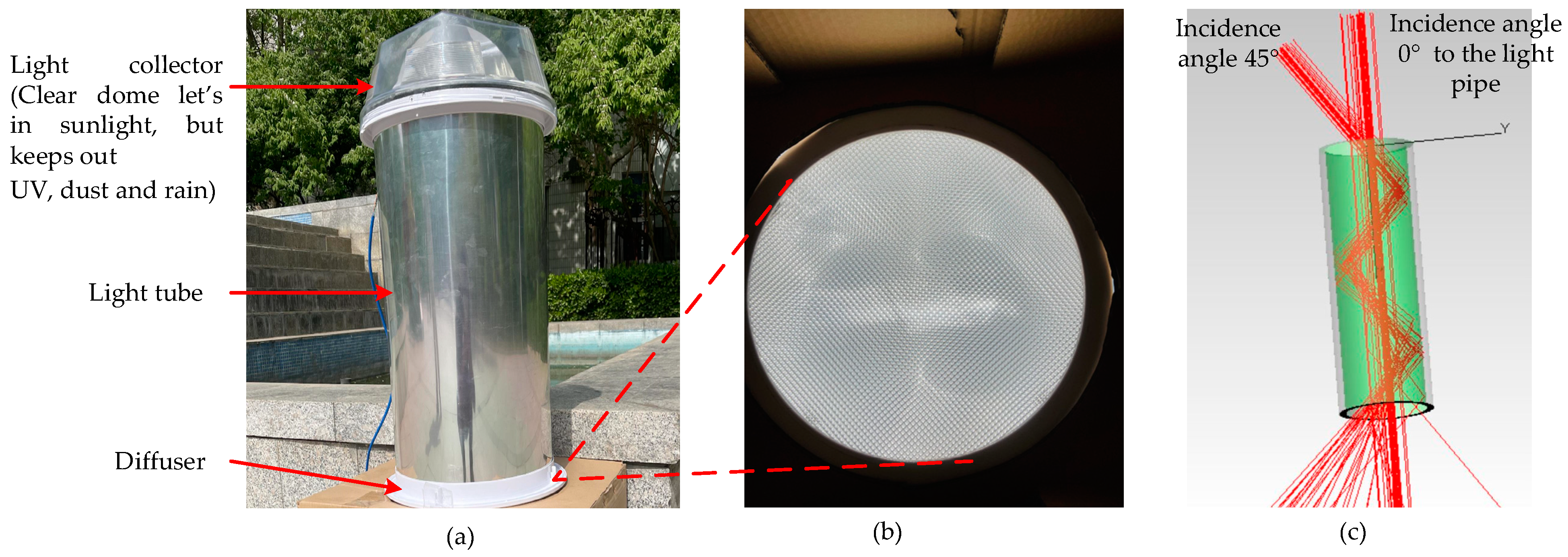
Figure 2.
Schematic diagram of the sun’s trajectory [83].
Figure 2.
Schematic diagram of the sun’s trajectory [83].
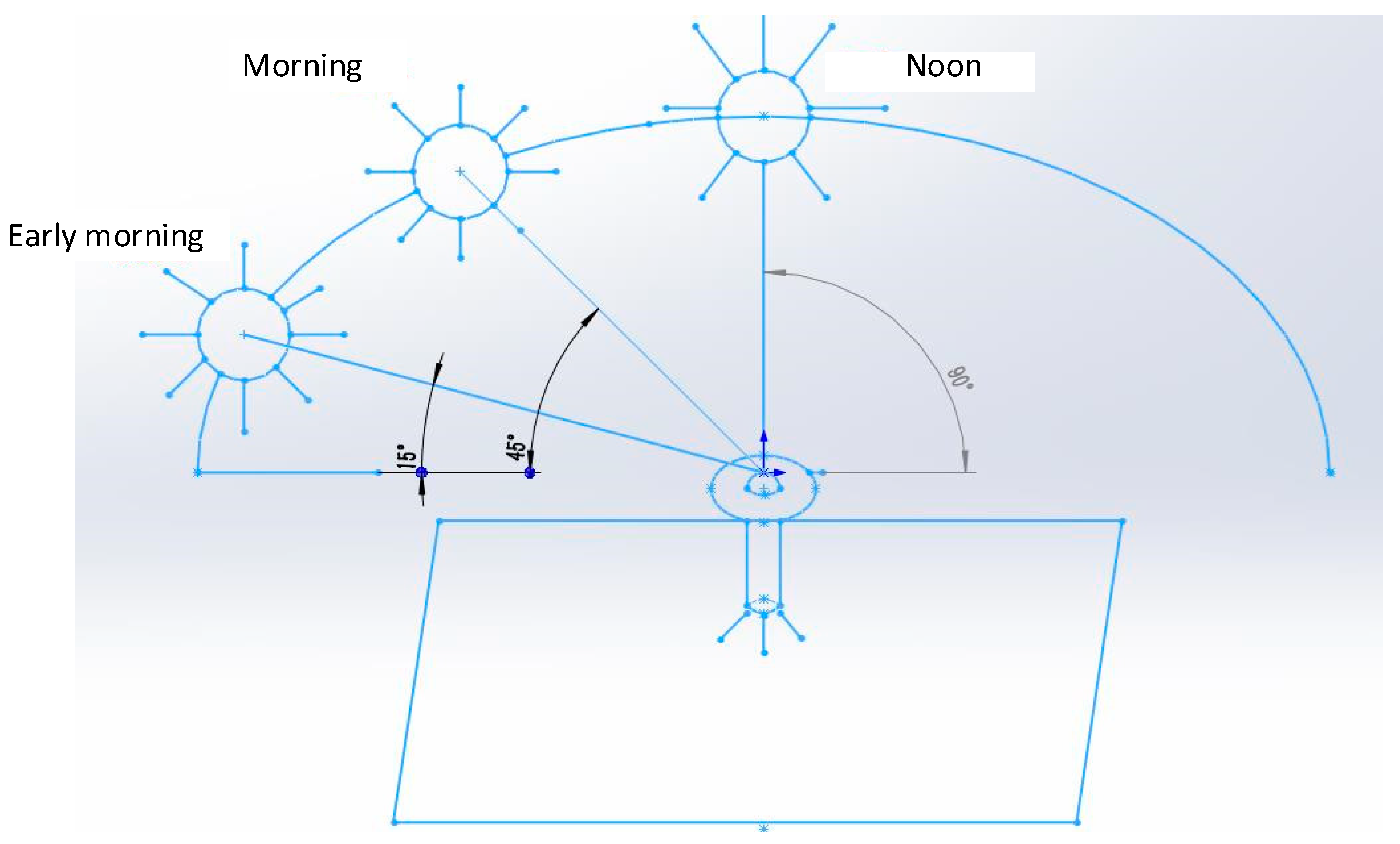
Figure 3.
Light pipe with bending angles of (a) 15°, (b) 45°, and (c) 90° [84].
Figure 3.
Light pipe with bending angles of (a) 15°, (b) 45°, and (c) 90° [84].
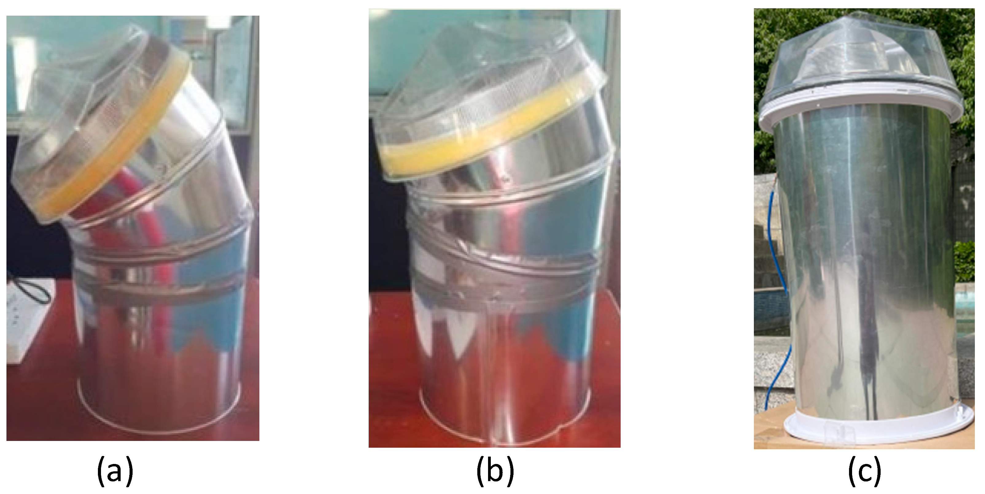
Figure 4.
Effect of the angle incidence and length of the pipe on light pipe efficiency.

Figure 5.
Structure of optical fiber and light refraction [95].
Figure 5.
Structure of optical fiber and light refraction [95].
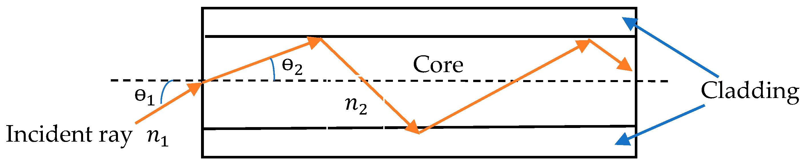
Figure 6.
Light path in the fiber core (a) when the incident angle in the air is less than the acceptance angle and the (b) light has an incident angle greater than the acceptance angle [57].
Figure 6.
Light path in the fiber core (a) when the incident angle in the air is less than the acceptance angle and the (b) light has an incident angle greater than the acceptance angle [57].

Figure 7.
The structure of the Fresnel lens-based daylighting system via optical fiber.

Figure 8.
Fresnel lens-based fiber daylighting system (a) ray path and (b) Homogenizer [96].
Figure 8.
Fresnel lens-based fiber daylighting system (a) ray path and (b) Homogenizer [96].

Figure 9.
Illumination distribution of PMMA optical fiber: (a) spotlight, (b) 2D distribution, and (c) 3D distribution.
Figure 9.
Illumination distribution of PMMA optical fiber: (a) spotlight, (b) 2D distribution, and (c) 3D distribution.
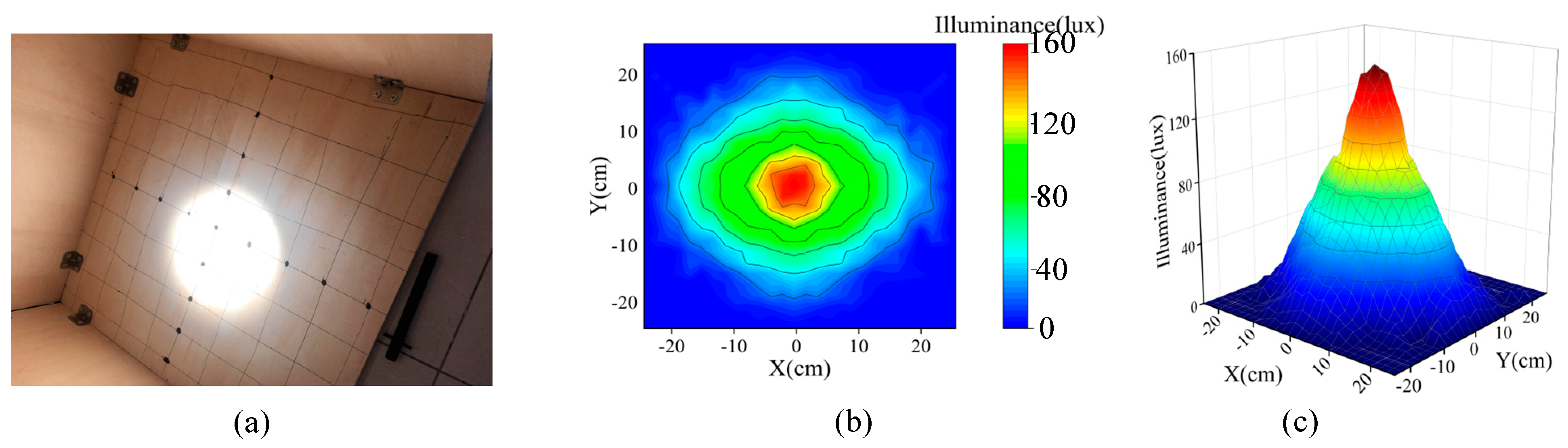
Figure 10.
Effect of incident angle on the transmittance and attenuation of PMMA optical fibers.

Figure 11.
PMMA fibers that melted because of overheating.
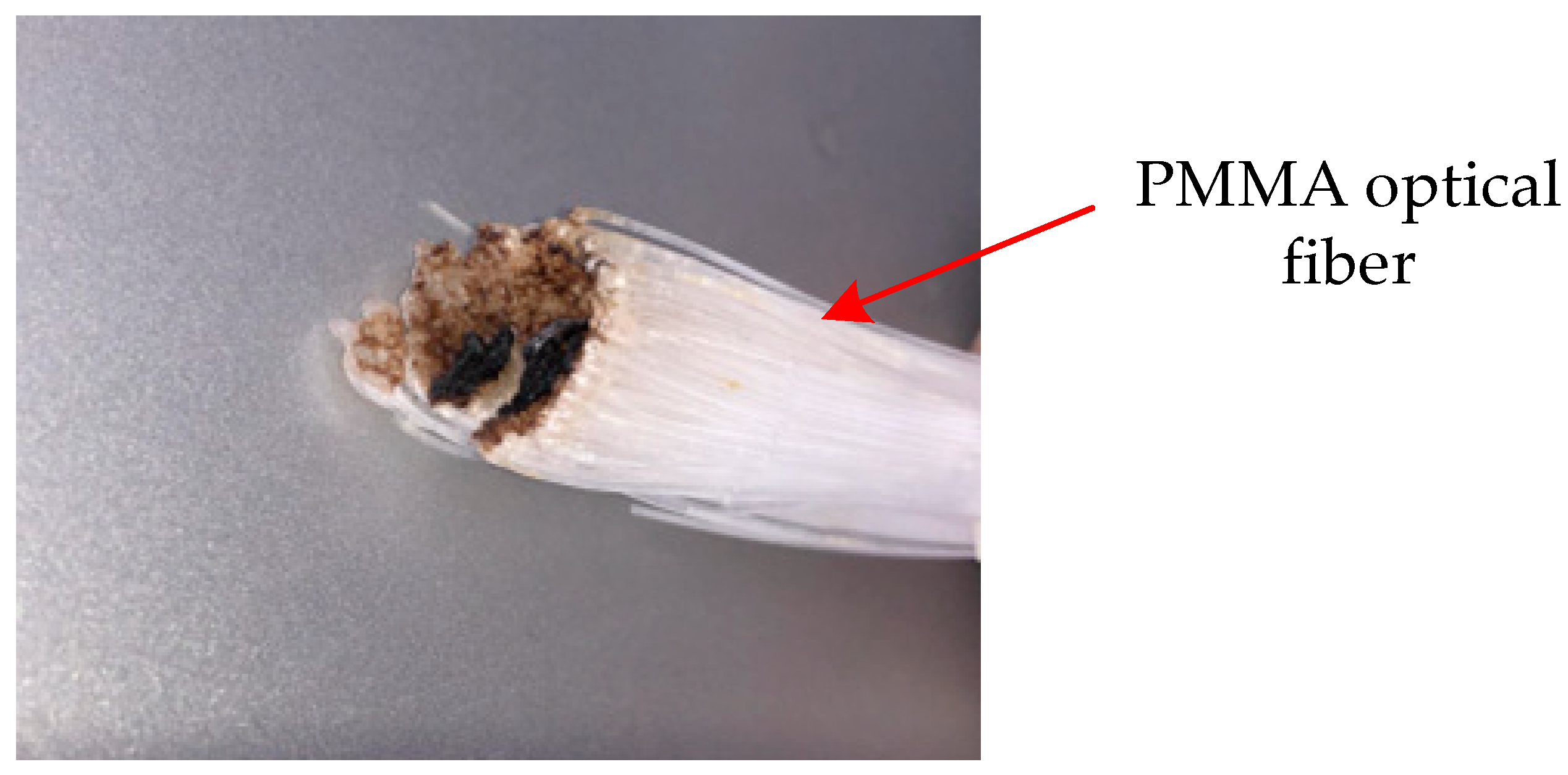
Figure 12.
Plastic optical fiber-based daylighting system and the spectrum of sunlight with different filtering mechanisms: (a) two-axis turntable structure; (b) schematic diagram; (c) IR filter; (d) heat-absorbing glass; (e) combination of infrared filter and heat-absorbing glass [108].
Figure 12.
Plastic optical fiber-based daylighting system and the spectrum of sunlight with different filtering mechanisms: (a) two-axis turntable structure; (b) schematic diagram; (c) IR filter; (d) heat-absorbing glass; (e) combination of infrared filter and heat-absorbing glass [108].
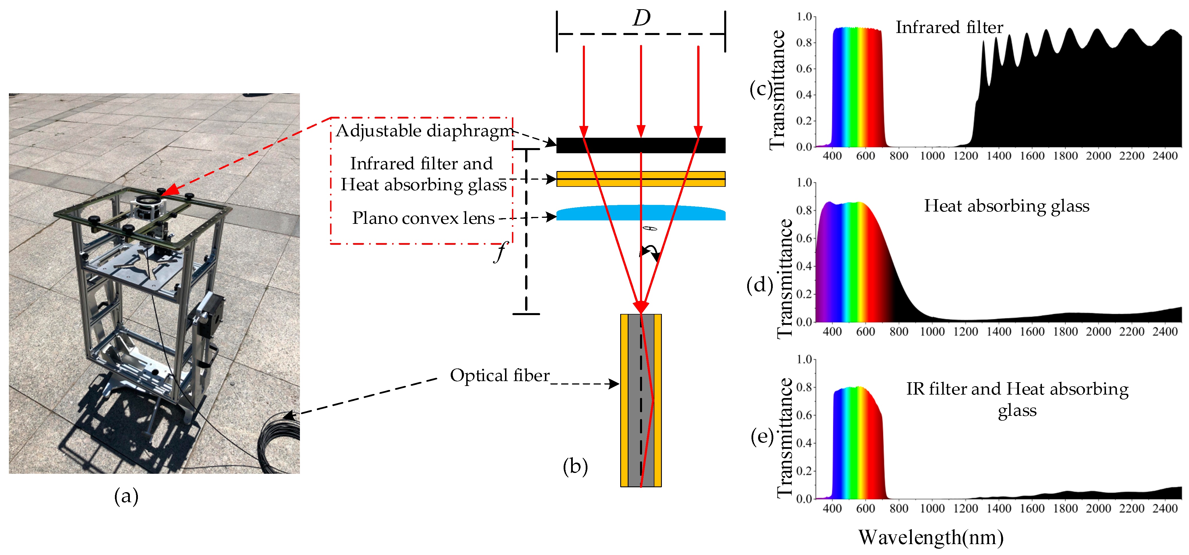
Figure 13.
PMMA optical fiber temperature rises, with filtering measures, under different solar concentrations (ambient temperature 30 °C) [113].
Figure 13.
PMMA optical fiber temperature rises, with filtering measures, under different solar concentrations (ambient temperature 30 °C) [113].
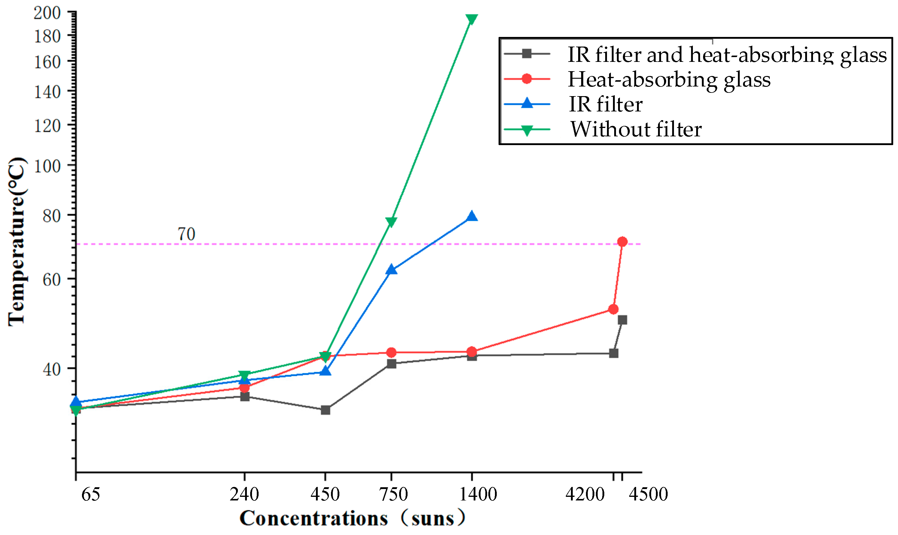
Figure 14.
Heliostat working principle and light path [115].
Figure 14.
Heliostat working principle and light path [115].
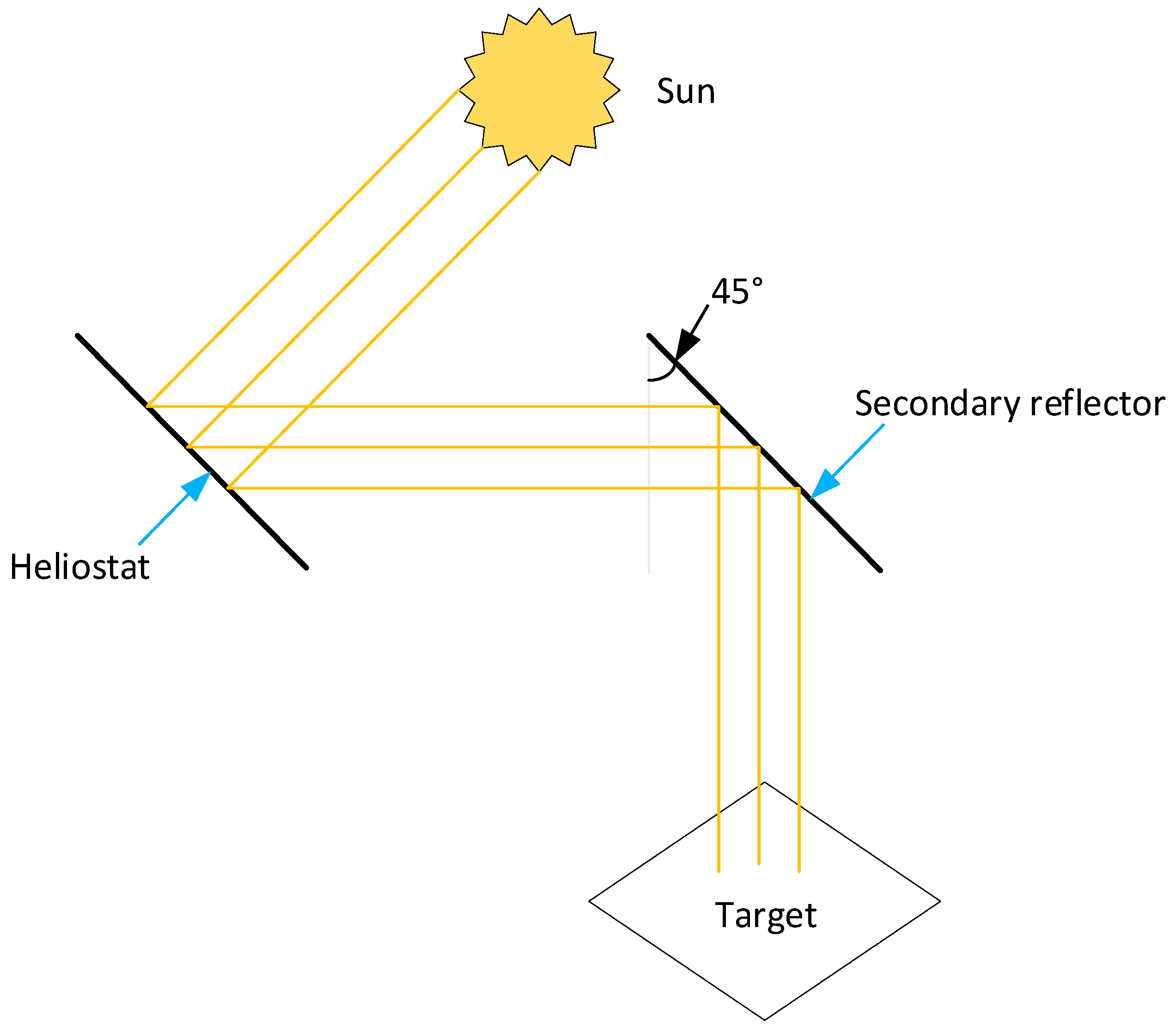
Figure 15.
The roof-mounted heliostat daylighting system.
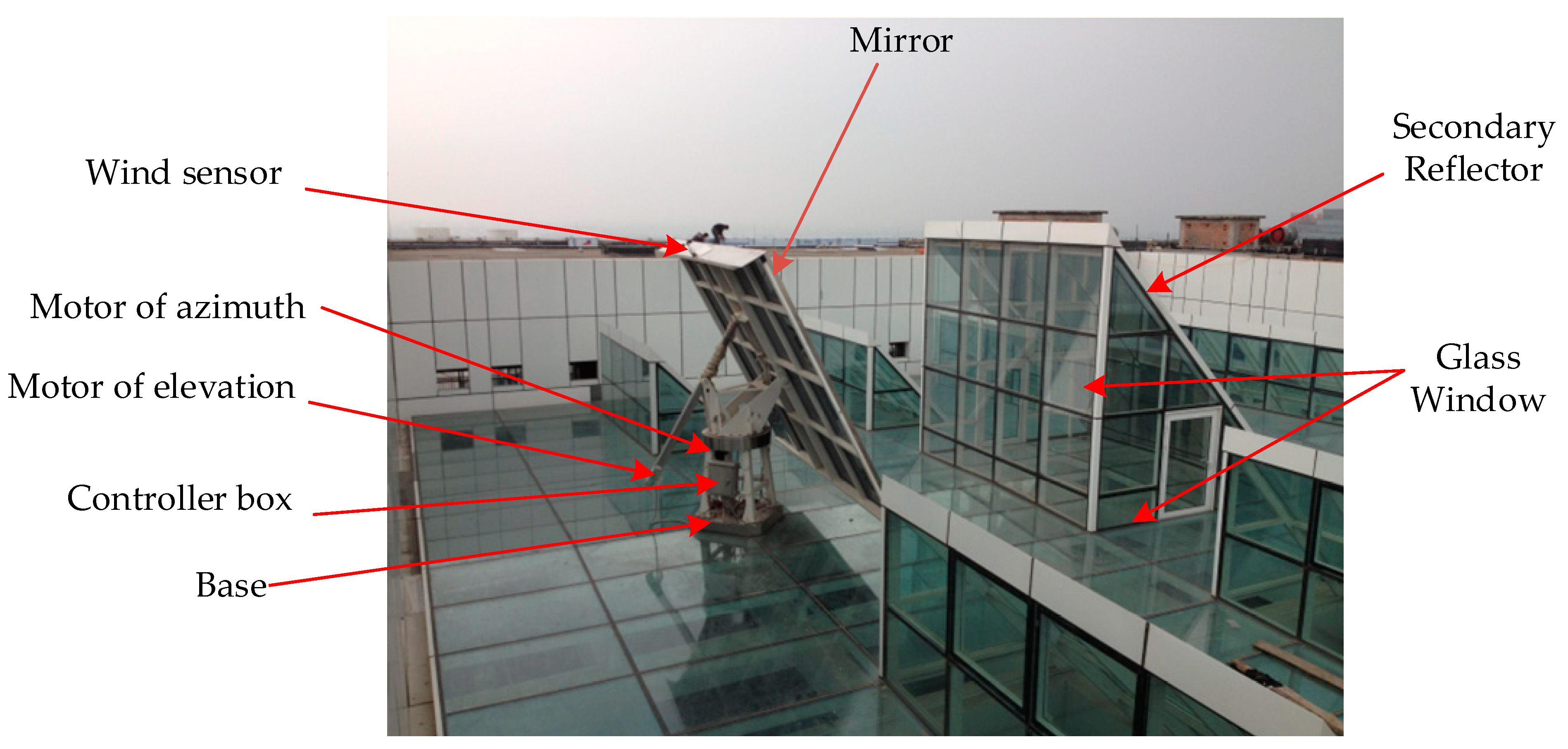
Figure 16.
Heliostat-based daylighting system for a large building: (a) eighth-floor light path, (b) daylighting on the ground, and (c) overall layout [75].
Figure 16.
Heliostat-based daylighting system for a large building: (a) eighth-floor light path, (b) daylighting on the ground, and (c) overall layout [75].
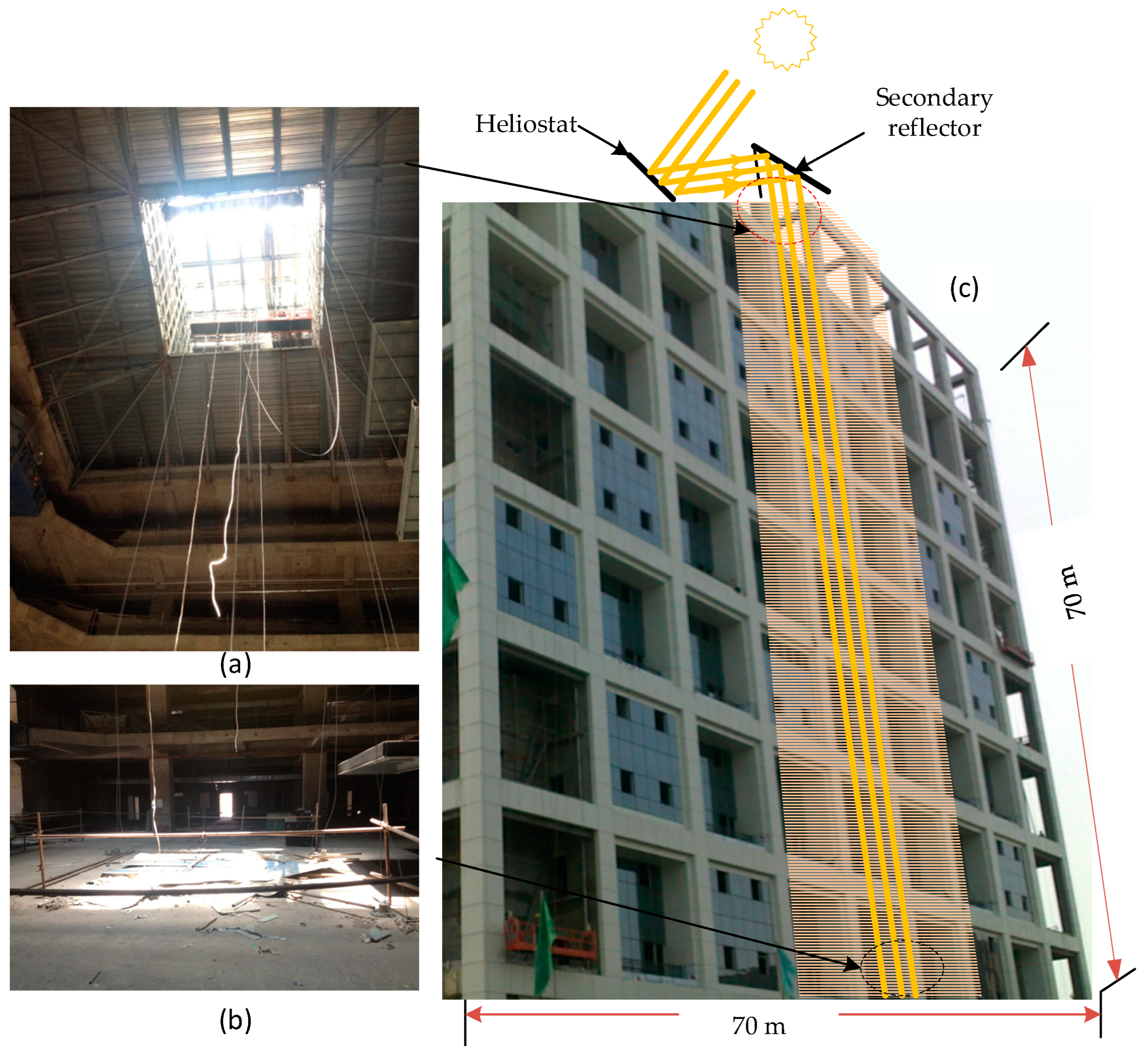
Figure 17.
Heliostat integrated with a sun position sensor [116].
Figure 17.
Heliostat integrated with a sun position sensor [116].
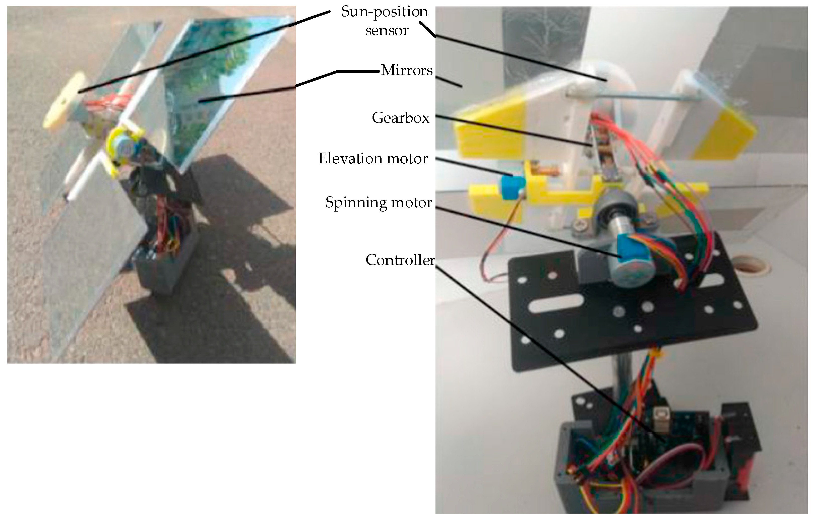
Figure 18.
Daylight spectrum: (a) nature light, (b) light pipe, (c) POF, (d) heliostat.

Figure 19.
Spectra of different light sources: (a) natural light, (b) PMMA optical fiber based daylighting, (c) tungsten incandescent lamp, (d) white LED, (e) fluorescent lamp [61].
Figure 19.
Spectra of different light sources: (a) natural light, (b) PMMA optical fiber based daylighting, (c) tungsten incandescent lamp, (d) white LED, (e) fluorescent lamp [61].

Figure 20.
CIE1931 chromaticity diagram [84].
Figure 20.
CIE1931 chromaticity diagram [84].


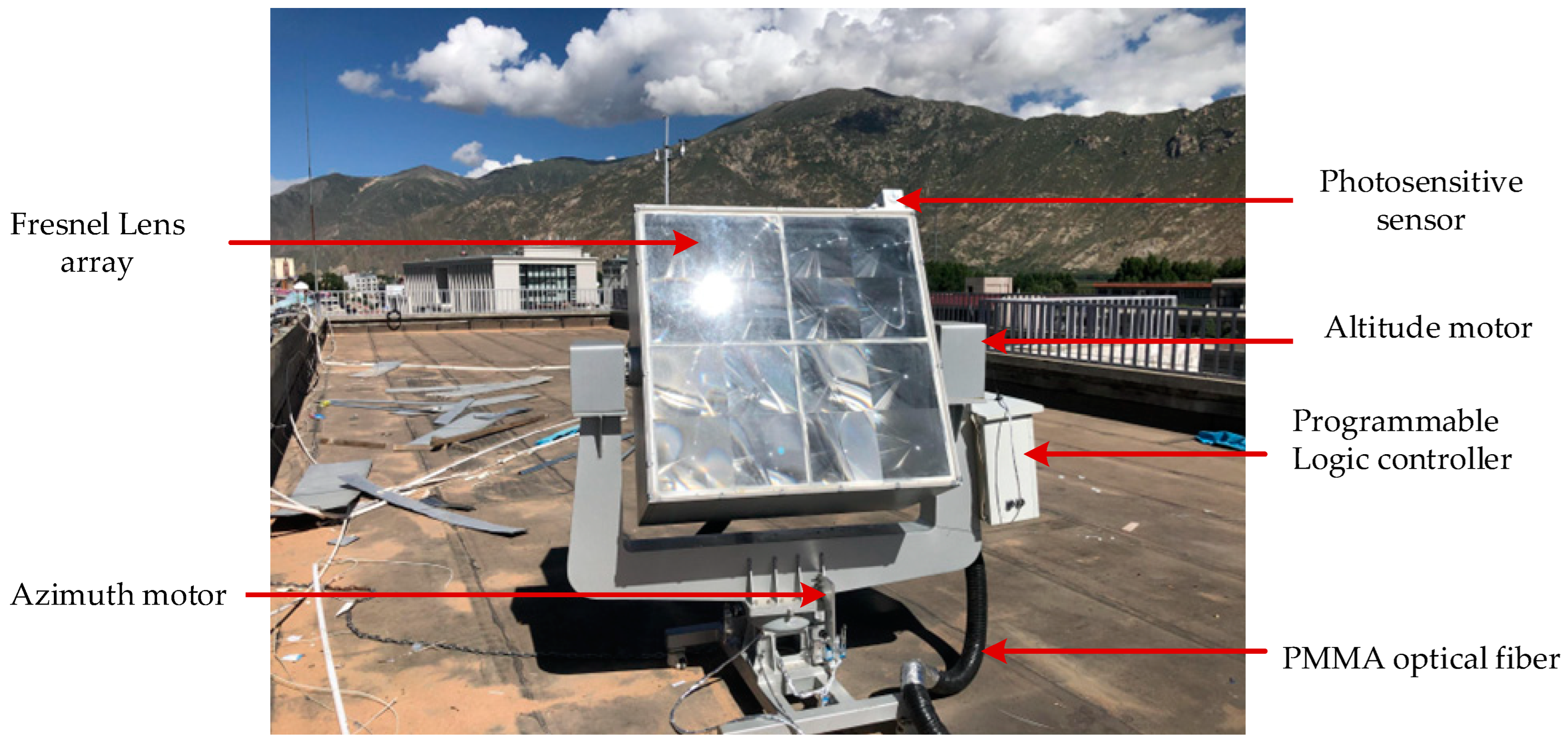
Table 1.
A summary of daylighting systems.
| DTT | Reference | Concentrator | Tracking | Structure | Length | Fiber Material | Collecting Area | Concentration Ratio | Type |
|---|---|---|---|---|---|---|---|---|---|
| Light Pipe | [41] | FPC | No | 6.5 m | PMMA | 0.29 m2 | – | Experiment | |
| [42] | Flat concentrator | No | 2.5 m | Acrylic | 0.36 | Experiment | |||
| [43] | No | No | – | 2.77–4 m | 0.0855 m2 | – | Experiment | ||
| [44] | No | No | – | 1 m | 0.049 m2 | – | Experiment | ||
| [45] | No | No | – | 3 m | 0.196 m2 | – | Experiment | ||
| [46] | No | No | – | 1.3 m | 0.332 m2 | – | Experiment | ||
| [47,48,49] | Fresnel lens | Yes | A–E | 12.5 m | 6.20 m2 | <100 | Experiment | ||
| [50] | Linear Fresnel lens | Yes | – | 15 m | 0.6 m2 | – | Simulation | ||
| Optical Fiber | [51] | Fresnel lens | Yes | A–E | 1 m | PMMA | – | – | Experiment |
| [52,53] | Fresnel lens | Yes | A–E | 10 m | PMMA | – | – | Experiment | |
| [54,55] | Fresnel lens | Yes | A–E | 6.7–11 m | Plastic | – | – | Experiment | |
| [56] | Fresnel lens | Yes | A–E | – | plastic | 0.09 m2 | 585 | Simulation | |
| [57] | Parabolic collector | Yes | – | 10 m | Plastic | 4.48 m2 | |||
| Flat optical reflector | |||||||||
| [58,59] | parabolic reflector | Yes | A–E | – | Silica + plastic | 0.09 m2 | – | Experiment | |
| Fresnel/dish | 0.0804 m2 | – | |||||||
| [60] | Fresnel lens | Yes | P–M | <20 m | PMMA | 0.48 m2 | <1634 | Experiment | |
| [61] | Fresnel lens | Yes | P–M | 10 m | PMMA | 0.48 m2 | 2500 | Experiment | |
| [29,62] | Convex lens | Yes | A–E | 200 m | Silica | – | 10,000 | Experiment | |
| [63] | Parabolic dish | Yes | A–E | 5 m | 0.07 m2 | – | Experiment | ||
| [64] | Parabolic dish | Yes | A–E | 3 m | PMMA | 0.785 m2 | 600 | Experiment | |
| [65] | Parabolic dish | Yes | A–E | 6 m | PMMA | 0.785 m2 | 976 | Experiment | |
| [66] | Fresnel lens | Yes | A–E | 10 m | PMMA | 0.073 m2 | – | Experiment | |
| [67] | Fresnel lens | Yes | A–E | 10 m | Liquid+ PMMA | 0.785 m2 | 3906 | Experiment | |
| [68] | Funnel concentrator | Yes | A–E | 5 m | Plastic | 0.000314 m2 | 100 | Experiment | |
| [7,69] | Mirrors | Yes | A–E | 10 m | PMMA | 0.2 m2 | <100 | Experiment | |
| [70,71] | Flat concentrator | No | A–E | 1 m | PMMA | 1.44 m2 | 25 | Experiment | |
| [72] | Fresnel lens | Yes | A–E | 2.5 m | PMMA | 0.0254 m2 | 400 | Experiment | |
| Heliostat | [46] | No | Yes | A–E | 12 m | 0.442 m2 | [73,74] | Experiment | |
| [27] | No | Yes | A–E | >26 m | 8.03 m2 | – | Experiment | ||
| [75] | No | Yes | A–E | 70 m | 22.95 m2 | – | Experiment | ||
| [76] | No | Yes | A–E | 1.85 m | 0.016 m2 | – | Experiment | ||
| [77] | No | Yes | S–E | 20 m | 0.1 m2 | [78,79] | Experiment |
DTT = daylight transport technology; FPC = fluorescent planar concentrator; A–E = azimuth–elevation; P–M = parallel mechanism; PMMA = polymethylmethacrylate; S–E = spinning–elevation.
Table 2.
Interior average irradiance at different incident angles.
| Light Pipe Length | Internal Average Irradiance (W/m2) | ||
|---|---|---|---|
| At Noon 15° | In the Morning 45° | In the Morning 90° | |
| 500 mm | 23.6 | 109.8 | 473 |
| 700 mm | 20 | 105.6 | 472 |
| 2000 mm | 12.8 | 68.4 | 447 |
Table 3.
Light pipe efficiency at different incident angles and pipe lengths.
| The Incidence Angle of The Sun | 15° | 45° | 90° | |
|---|---|---|---|---|
| Light Pipe Length | ||||
| 500 mm | 5.90% | 18.30% | 47.30% | |
| 700 mm | 5.50% | 17.60% | 47.20% | |
| 2000 mm | 3.20% | 11.40% | 44.70% | |
Table 4.
Parameters for the comparison of daylighting technologies.
| Parameters | Light Pipes | Optical Fiber | Heliostat |
|---|---|---|---|
| Materials used | Al/Ag | PMMA | Mirrors |
| Spectrum | Natural spectrum | Very close to the natural spectrum | Natural spectrum |
| Transmission efficiency (%) | 44.7 | 18 | 23 |
| Transmission distance (m) | 2 | 20 | 70 |
| Photo effect (lm/w) | 150 | 220 | 110 |
| Color rendering index (CRI) | 98.9 | 89.1 | 98.3 |
Table 5.
Summary of daylighting technologies advantages and disadvantages.
| Daylighting Technologies | Advantages | Disadvantages |
|---|---|---|
Light pipes |
|
|
Plastic Optical fiber |
|
|
Heliostat |
|
|
Disclaimer/Publisher’s Note: The statements, opinions and data contained in all publications are solely those of the individual author(s) and contributor(s) and not of MDPI and/or the editor(s). MDPI and/or the editor(s) disclaim responsibility for any injury to people or property resulting from any ideas, methods, instructions or products referred to in the content. |
© 2023 by the authors. Licensee MDPI, Basel, Switzerland. This article is an open access article distributed under the terms and conditions of the Creative Commons Attribution (CC BY) license (https://creativecommons.org/licenses/by/4.0/).
Share and Cite
MDPI and ACS Style
Song, J.; Dessie, B.B.; Gao, L. Analysis and Comparison of Daylighting Technologies: Light Pipe, Optical Fiber, and Heliostat. Sustainability 2023, 15, 11044. https://doi.org/10.3390/su151411044
AMA Style
Song J, Dessie BB, Gao L. Analysis and Comparison of Daylighting Technologies: Light Pipe, Optical Fiber, and Heliostat. Sustainability. 2023; 15(14):11044. https://doi.org/10.3390/su151411044
Chicago/Turabian StyleSong, Jifeng, Bizuayehu Bogale Dessie, and Longyu Gao. 2023. "Analysis and Comparison of Daylighting Technologies: Light Pipe, Optical Fiber, and Heliostat" Sustainability 15, no. 14: 11044. https://doi.org/10.3390/su151411044
Note that from the first issue of 2016, this journal uses article numbers instead of page numbers. See further details here.