Article

New Evacuated Tube Solar Collector with Parabolic Trough Collector and Helical Coil Heat Exchanger for Usage in Domestic Water Heating

1
Laboratory of Energy and Materials (LabEM-LR11ES34), Higher School of Science and Technology of Hammam Sousse (ESSTHS), University of Sousse, Street Lamine Abbassi, Hammam Sousse 4011, Tunisia
2
Mechanical Engineering Department, College of Engineering, Jazan University, Jazan 45142, Saudi Arabia
3
Mechanical Engineering Department, College of Engineering, King Khalid University, Abha 9004, Saudi Arabia
*
Author to whom correspondence should be addressed.
Sustainability 2023, 15(15), 11497; https://doi.org/10.3390/su151511497
Submission received: 22 May 2023 / Revised: 9 July 2023 / Accepted: 19 July 2023 / Published: 25 July 2023
(This article belongs to the Special Issue Applications of Renewable Energy Technologies on Buildings)

Abstract

:
Buildings represent approximately two-thirds of the overall energy needs, mainly due to the growing energy consumption of air conditioning and water heating loads. Hence, it is necessary to minimize energy usage in buildings. Numerous research studies have been carried out on evacuated tube solar collectors, but to our knowledge, no previous study has mentioned the combination of an evacuated tube solar collector with a parabolic trough collector and a helical coil heat exchanger. The objective of this paper is to evaluate the thermal behavior of an innovative evacuated tube solar collector (ETSC) incorporated with a helical coil heat exchanger and equipped with a parabolic trough collector (PTC) used as a domestic water heater. To design the parabolic solar collector, the Parabola Calculator 2.0 software was used, and the Soltrace software was used to determine the optical behavior of a PTC. Moreover, an analytical model was created in order to enhance the performance of the new model of an ETSC by studying the impact of geometric design and functional parameters on the collector’s effectiveness. An assessment of the thermal behavior of the new ETSC was performed. Thus, the proposed analytical model gives the possibility of optimizing ETSCs used as domestic water heaters with lower computational costs. Furthermore, the optimum operational and geometrical parameters of the new ETSC base-helical tube heat exchanger include a higher thermal efficiency of 72%. This finding highlights the potential of the heat exchanger as an excellent component that can be incorporated into ETSCs.

1. Introduction

Since energy consumption is increasing quickly nowadays due to the growing global population, it is important to look for alternative energy sources. Researchers and experts have been focusing on harvesting solar energy due to its benefits including its being regarded as the most readily available and ecologically beneficial renewable energy source [1,2,3,4]. Among other solar systems, solar thermal collectors are widely used to harvest solar energy and convert it into thermal energy. There are two categories of solar thermal collectors: stationary and tracking [5]. Stationary collectors include evacuated tube solar collectors and flat plate solar collectors. ETSCs are more effective than FPCs in cold weather due to their higher operating temperatures, which can reach as high as 120 °C. Moreover, an ETSC’s high thermal efficiency and relatively low cost make it a highly competitive collector in the market [1,3,4,6,7]. A parabolic solar collector is considered a concentrated solar power (CSP) plant system that uses a parabolic-shaped mirror to focus sunlight into its receiver (volumetric or tube absorber) in order to create a high temperature of heat transfer fluid [1,8]. Parabolic trough collectors (PTCs) are designed to track the sun during the daytime in order to absorb the maximum quantity of solar intensities and transform it into thermal energy, which can be utilized for generating electricity by using steam turbines or other generators—or heating fluid for industrial and residential purposes—or for agricultural purposes such as drying crops [1,9,10,11]. PTCs are known to be adaptable, flexible, versatile, powerful, modular, productive, long-lasting, and compatible with the majority of heat transfer fluids (HTF) [8,12]. PTCs generate electricity by heating up to 400 °C while using thermal oils [8,13]. However, parabolic trough collectors have some drawbacks including high cost, large area requirement, weather dependence, and the deformation of their receivers over time [8,14]. Several research studies have been conducted on evacuated tube solar collectors, specifically focusing on assessing their thermal performance. For instance, some studies have experimentally evaluated the performance of an ETSC with a heat pipe design. Additional studies have examined, numerically, the addition of phase-change materials to evacuated tube solar collectors. Reviews of evacuated tube solar collectors are also available. Researchers have attempted to integrate parabolic trough collectors with ETSCs to enhance the overall performance of evacuated tube solar collectors. Saurabh Pandey et al. [15] carried out an experimental study in order to boost the effectiveness of an evacuated U-tube solar collector incorporated with a parabolic trough solar collector used for air heating. By employing various mass flow rates, the authors found that a mass flow rate of 0.0082 Kg/s yielded the highest average thermal effectiveness (21.3%). Additionally, the solar collector attained the highest average outlet temperature (122.9 °C) at a mass flow rate of 0.0062 Kg/s. Tzivanidis et al. [16] carried out a numerical study using Solidworks on an evacuated tube solar collector that acted as a receiver for a parabolic solar collector. They evaluated the system’s efficiency and investigated the heat transfer processes inside the collector. The results demonstrate that such a collector provides a high efficiency of 75% when operating at high temperatures. In addition, the heat loss coefficient ranges between 0.6 and 1.3 W/mηK. Elarem et al. [17] studied, numerically, the effect of the parabolic reflector on the outlet HTF temperature inside a direct flow evacuated tube solar collector equipped with copper fins and integrated with PCM nanoparticles. Their findings demonstrated that using a PTC improves the efficiency of an ETC. The study also revealed that decreasing the thickness of the fins results in the faster melting of the PCM. Moreover, in the study, the addition of 1% Cu to the PCM led to a 2 K rise in the HTF outlet temperature. Sarah et al. [18] examined the impact of a porous medium on the productivity of a PTC integrated into a direct flow evacuated tube solar collector equipped with a U-tube heat exchanger. According to the findings, the solar collector yielded an efficiency of 62,4% without the use of porous media. Moreover, by enhancing the solar system with an aluminum fiber metallic with 99.97% porosity, the efficiency reached 79.4%. B. Kiran et al. [19] assessed, experimentally and numerically, the productivity of a direct flow evacuated tube solar collector with a U-tube heat exchanger integrated with a parabolic reflector. The performance of this modified collector was compared to that of a conventional direct flow collector. The study’s findings revealed that for different solar intensities, the modified ETSC exhibited an HTF with an outlet temperature 2.4 °C higher than the HTF provided by a typical collector. Furthermore, the efficiency rose by 14.1% compared with the typical collector. Abo-Elfadl et al. [20] experimentally affixed two glass reflectors at varying angles to examine the performance of an ETSC with and without the presence of solar reflectors. Their results showed that incorporating the upper, lower, and both reflectors led to increases of 15.3%, 22.5%, and 37% in input energy to the collector, respectively. Moreover, the daily accumulated energy increased by 14%, 22.1%, and 35.7%, respectively. Mohsen Rezaeian et al. [21] experimentally investigated a U-pipe ETSC equipped with a PTC. The authors utilized both distilled water and a nanofluid (a nanoparticle of CuO) as working fluids. Their results showed that the highest performance index and the highest efficiency recorded were 1.74 and 71%, respectively, while employing a 5 L/min mass flow rate and a 0.08% nanofluid fraction. M. Khairat Dawood et al. [22] carried out an experimental study in order to boost the effectiveness of a conventional single solar still by connecting a PTC to an ETSC equipped with a helical heat exchanger and an under-tank PCM. The authors studied the impact of using three different working fluids, each operating at different mass flow rates: 0.5, 1, and 1.5 L/min. Their results demonstrated that while deploying a nanofluid as a working fluid, efficiency and daily productivity increased by 21.5% and 250%, respectively. Syed Farhad Shah et al. [23] elaborated a mathematical model to boost the HTF outlet temperature generated by an evacuated tube solar collector connected to a series of PTCs. Copper tubes were installed within the evacuated tubes of the collector. According to the results, the system efficiency increased by 37% as the mass flow rates rose. Hassan Fathabadi [24] proposed a novel study in which he analyzed the effect of adding a parabolic collector and single- and double-axis sun trucking on the thermal efficiency of an ETSC. Moreover, a cost–benefit numerical study was undertaken to compare the four models. The authors found that the yearly thermal efficiency was 52.31%, whereas adding a parabolic reflector had yielded a 42.65% average annual efficiency. The third and fourth collectors had thermal efficiencies of 56.32% and 58.60%, respectively. The fourth collector cost the most among the collectors, with a ratio of EUR 4.44 per percent. Although there have been several studies conducted on integrating parabolic trough collector systems with evacuated tube solar collectors [24,25,26], the most common type of heat exchanger used in ETSCs is the heat pipe design. Another form of heat exchanger that is widely employed in ETSCs is the U-tube heat exchanger. This work intends to fill a research gap in the deployment of helical coil heat exchangers in ETSCs. Hence, the principal goal of this study is to design a new model of a direct flow evacuated tube solar collector and examine the influence of the incorporation of a PTC into it. Additionally, the purpose of this study is to develop an analytical model in order to identify the optimal geometric and operational parameters that contribute to improving the efficiency and productivity of the proposed ETSC.

2. Description of the ETSC

The aim of this research is to investigate the overall behavior of an evacuated tube solar collector equipped with a helical coil heat exchanger and connected to a PTC. The studied model of ETSC consists of two glass tubes enclosed in a vacuum. The inner glass tube is covered with a specific material and linked directly to a copper helical tube. A heat transfer fluid (water) circulates inside the helical tube. The deployment of a helical coil tube as a heat exchanger equipped within the ETSC enhances its efficiency due to its ability to expand the surface area of the HTF. A 5730 mm helical tube with 59 turns and an outer diameter of 54 mm was installed inside the evacuated tube. The helical tube is made of a thermally conductive material, such as copper, and covered with a selective layer that helps absorb the sun’s rays. As the helical tube heats up, it transfers the heat to the HTF inside it, which can be employed for domestic use. The helical tube design allows for a larger surface area for heat transfer, which increases the efficiency of the ETSC. The addition of a PTC can significantly impact the functionality of an ETSC. A PTC can augment the solar intensity absorbed by the solar collector, which can ameliorate the ETSC’s efficiency. The integration of a PTC can also boost the energy intake and efficiency of the ETSC, increasing the heat gain as well. Therefore, the combination of a helical coil evacuated tube solar collector with a PTC provides an HTF with a higher temperature and enhances the efficiency of the solar system.
To design the parabolic solar collector, the Parabola Calculator 2.0 software was used. This program can calculate the focal length of a parabolic trough collector by taking into account the dimensions of the collector, such as the diameter (collector aperture), the depth, and the rim angle. By interfacing these parameters, the software generates the parabolic curve and determines the focal length of the collector. This process helps us design an efficient and high-performance design capable of concentrating solar rays onto a small area. Figure 1 presents the interface of the software utilized in this study. The geometric parameters of the solar collector are listed in Table 1. Figure 2 showcases both the parabola calculator software utilized in this work as well as the focal length of the parabolic trough collector determined using this software.

3. Mathematical Model

To assess the efficiency of the proposed ETSC, a mathematical model was employed at steady-state conditions. Several assumptions were made to make the model easier to design:
-
The energy loss occurring between the external cover of the solar collector and the surrounding area is similar to the thermal loss between the heat exchanger and the cover.
-
The heat transfer coefficient is assumed to be uniform along the tube.
-
The temperatures of the heat exchanger and HTF are practically equivalent.
-
The convective heat transfer coefficient between the surrounding environment and the glass tube is constant.
According to the mentioned hypothesis, the mathematical model is presented by the following equations.
The incident solar energy is calculated as follows [16,27,28,29,30,31]:
Q s = A a G
where G is the direct solar irradiation and A a is the aperture area.
Due to the presence of a vacuum between the absorber tube and the cover, the only type of thermal loss occurring in that area is radiation [32,33,34]. The expression of thermal loss is presented as follows [32]:
Q l o s s = 4 T i n 3 K 1 K 3 Q u + K 1 T i n 4 T a m 4
Here ,   K 1 = A r o ε r * σ 1 + 4 T a m 3 ε r * σ A r o A c o ε c σ 4 T a m 3 + A c o h o u t 1
ε r * is the equivalent emittance, calculated as follows:
ε r * = 1 ε r + 1 ε c ε c A r o A c i 1
When the working fluid absorbs solar irradiation, its temperature rises, resulting in useful energy ( Q u ) [16,28,32,35].
Q u = m ˙ C p T o u t T i n
To determine the mechanism of heat transfer within the helical tube, the useful heat can be represented as a function of heat transfer between the absorber tube and the working fluid [28,32].
Q u = A r h ( T r T f m )
Here, T f m is the fluid mean temperature [29,32].
T f m = T i n + T o u t 2
Using Equations (5) and (7), the expression of the useful heat is represented below [32]:
Q u = ( T r T i n ) 1 A r i h + 1 2 m ˙ C p = K 2 ( T r T i n )
where
K 2 = 1 A r i h + 1 2 m ˙ C p 1
Based on the energy conservation equation, the energy absorbed inside the ETSC is converted into thermal losses and useful energy.
η o p t . Q s = Q u + Q l o s s
Using Equations (1), (2), (8) and (10), the following may be written:
Q u = η o p t Q s K 1 ( T i n 4 T a m 4 ) 1 + 4 T i n 4 K 1 K 2 1
or
Q u = K 3 Q s K 4 ( T i n 4 T a m 4 )
where
K 3 = η o p t 1 + 4 K 1 T i n 3 K 2 1   and   K 4 = K 1 1 + 4 T i n 3 K 1 K 2 1
The HTF outlet temperature (Tout) may be calculated using Equations (5) and (12).
T o u t = T i n + K 3 m ˙ C p Q s K 4 m ˙ C p T i n 4 T a m 4
The thermal efficiency ( η t h ) of the ETSC is presented as follows [30]:
η t h = Q u Q s = η o p t Q l o s s Q s
Using Equations (1) and (12), the following may be written:
η t h = K 3 K 4 T i n 4 T a m 4 A a G
The heat transfer coefficient between the HTF and the helical tube is a significant parameter that can influence the efficiency of the system and can be calculated by using the Nusselt number. The convection coefficient expression is provided below [28,30,32]:
h = N u λ D r i
The Nusselt number for forced convection is presented in Equation (17) [35,36,37].
N u = 0.0345 R e 0.48 D d 0.914 P d 0.281
Here, d is the diameter of the helical tube, D is the helical diameter, and P is the pitch of the helical coil tube.
The Reynold number is defined by this expression:
R e = 4 m ˙ π D r i μ
The Prandtl number is defined as below:
P r = μ C p λ

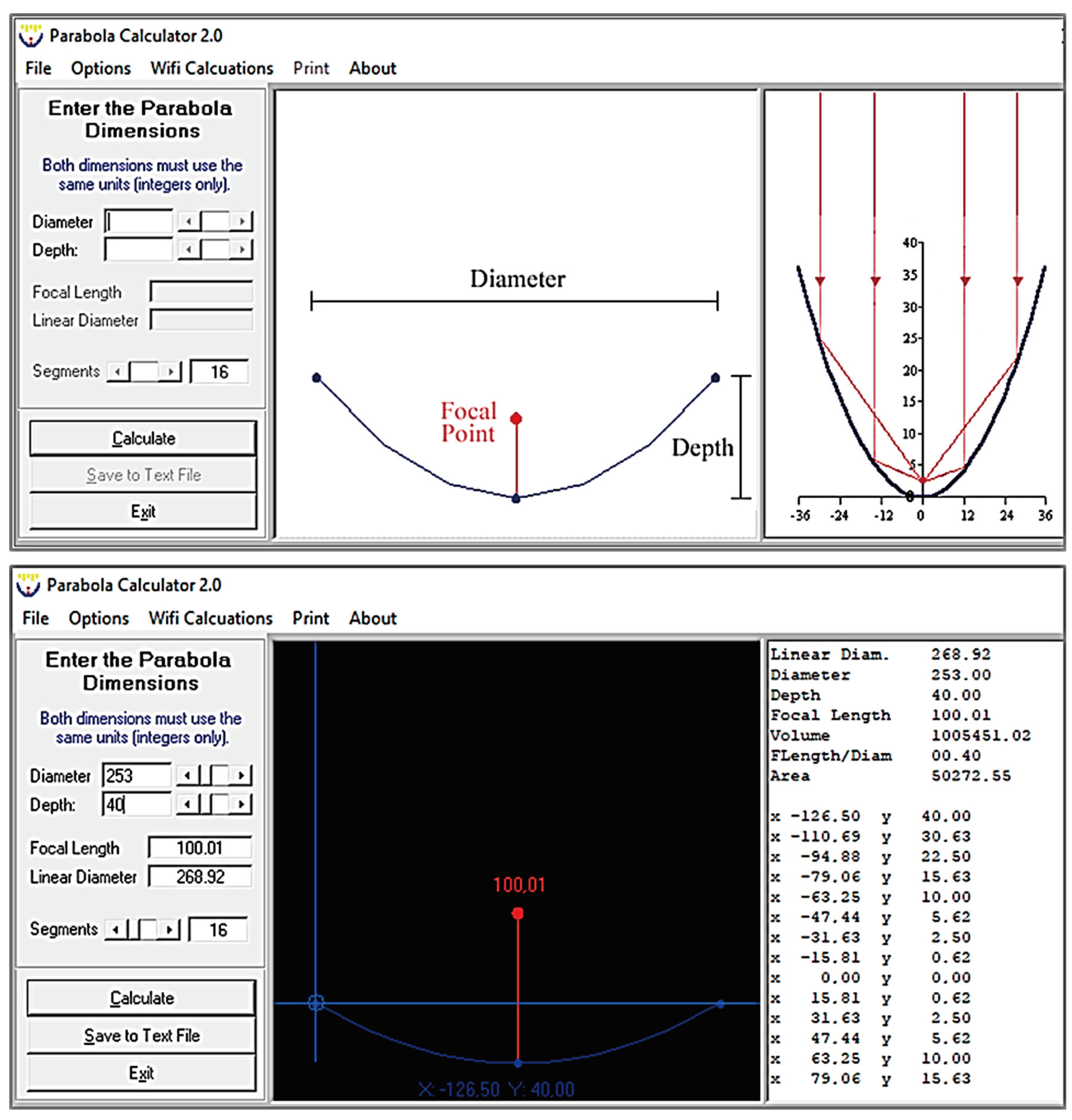
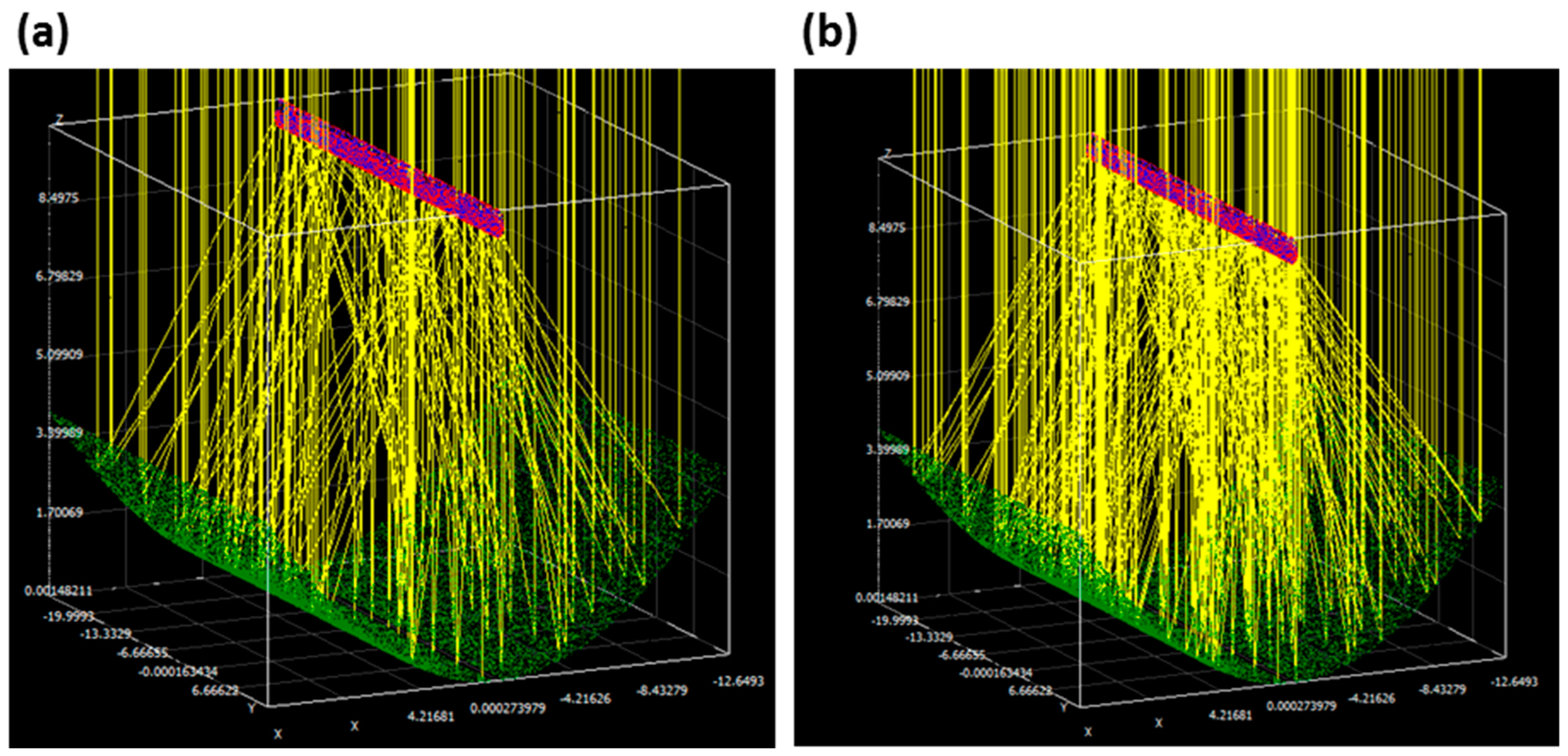
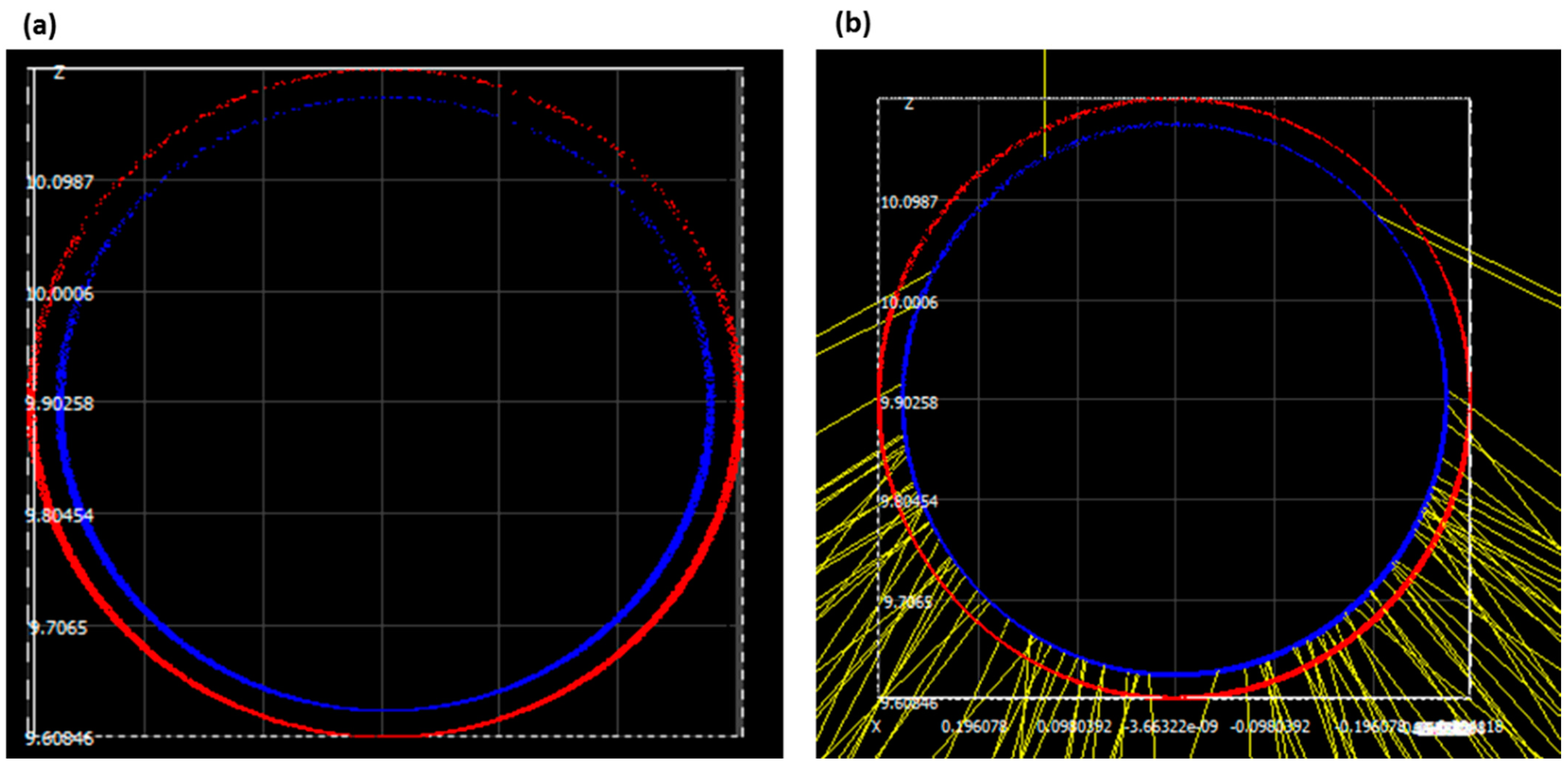
4. Simulation of the Solar Radiation toward an ETSC Integrated with a Parabolic Trough Solar Collector

The simulation of the solar radiation propagation surrounding the ETSC was carried out using the software Soltrace. This is an optical modeling program created by the National Renewable Energy Laboratory (NREL). Its code employs the approach of tracing solar radiation based on the Monte Carlo method to simulate the paths of solar rays as they reflect and refract through a concentrating solar power system [38,39]. Soltrace’s simulation is based on five principles: solar shape, optical properties, geometry, trace options, and results. A prototype of a direct flow evacuated tube solar collector integrated with a parabolic through solar collector was created in Soltrace to carry out the sensitivity study by employing the properties listed in Table 1. The simulation was performed with 2.5 million rays originating from the solar disk and launched toward the parabolic through the solar collector with a sunlight flux of 1000 W/m2. The sun’s shape is defined as a pillarbox with 4.65 mrad. This model was considered a single stage. Table 2 lists the ETSC’s optical properties, which were employed in this study.

5. Results and Discussions

A numerical study was conducted to identify the optimal operational and geometric parameters used to improve the functionality of a new evacuated tube solar collector equipped with a helical coil heat exchanger and connected to a parabolic trough solar collector.

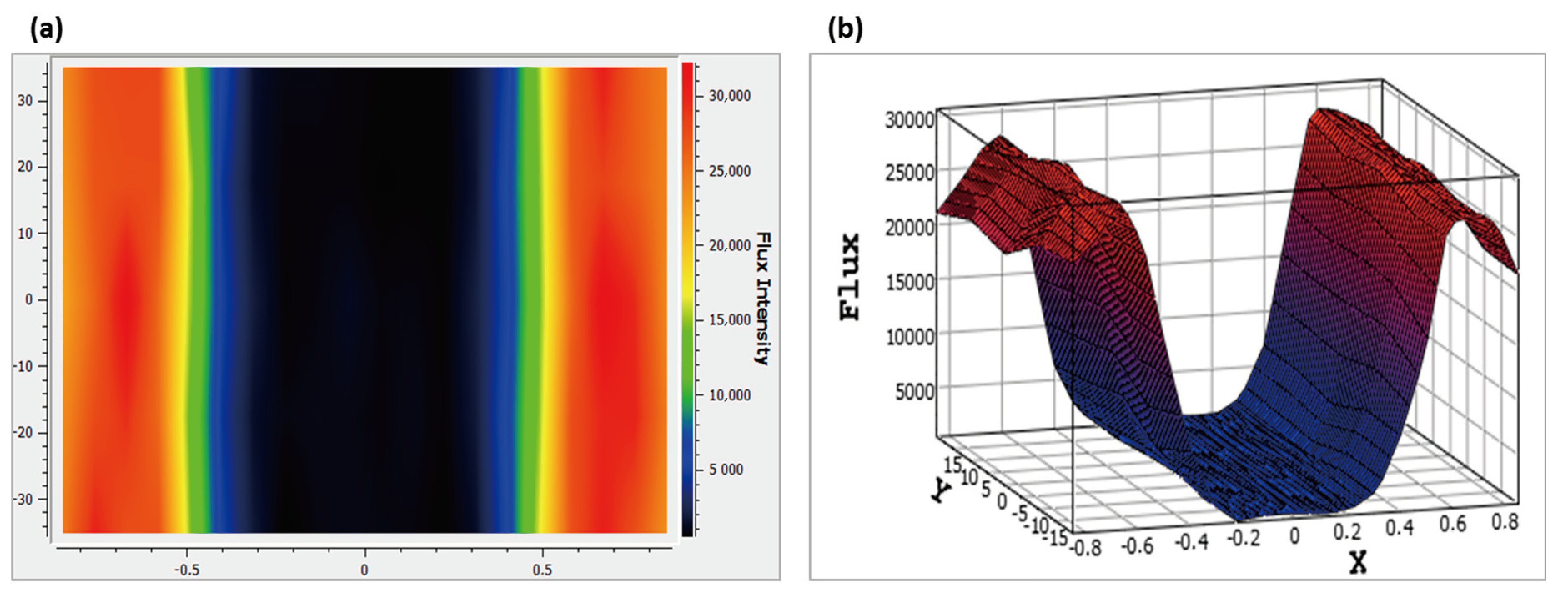
5.1. Simulation of the Solar Radiation

A numerical study took place using Soltrace to examine the sensitivity of flux propagation toward the ETSC.
Figure 3 presents a view of the rays’ intersection with the ETSC using 100 and 200 rays, while Figure 4 illustrates a close view of the ETSC, where Figure 4a shows the design of the evacuated tube and Figure 4b shows the intersection of solar rays on the ETSC.
The solar flux pattern surrounding the outside wall of the helical tube is depicted in Figure 5. As shown in Figure 5, the heat intensity distribution over the ETSC is not the same at every point. The flux distribution can be divided into three parts with different levels of heat flux. In the first part, the heat flux reaches a peak value of 30,690.6 W/m2. The second part shows a rapid decrease in the heat flux, reaching a minimum peak value of 477.507 W/m2. This decrease can be explained by fewer incident rays toward the parabolic solar collector in that specific area. In the third part, the heat flux reaches a maximum peak similar to that in the first part. These findings suggest that connecting a PTC to an ETSC can improve its performance. Additionally, according to the results given by the Soltrace simulation, the distribution of the heat flux over the glass tube shows an average flux of 13,059.8 W/m2 +/− 4.21076%. However, the distribution over the absorber tube shows that the average flux is higher, with a value of 13,441.7 W/m2 +/− 0.374768%. These results are similar to those found by reference [41].
The observed heat flux distribution reveals a non-uniform capture of heat within the solar collector. This suggests the potential for enhanced system performance by integrating a parabolic trough solar collector with an evacuated tube solar collector. The parabolic trough solar collector captures direct solar intensities and transfers them to the evacuated tube solar collector. The solar collector receives both solar intensities directly from the sun as well as reflected intensities from the parabolic trough solar collector. The variation of heat flux across the surface of the solar collector is attributed to the irregular distribution of heat transfer. Consequently, the intensity of heat flux varies at different points within the evacuated tube, resulting in temperature variations within the absorber tube. These results allow us to understand the heat flux arrangement within the solar system and evaluate the overall thermal performance of the evacuated tube solar collector.

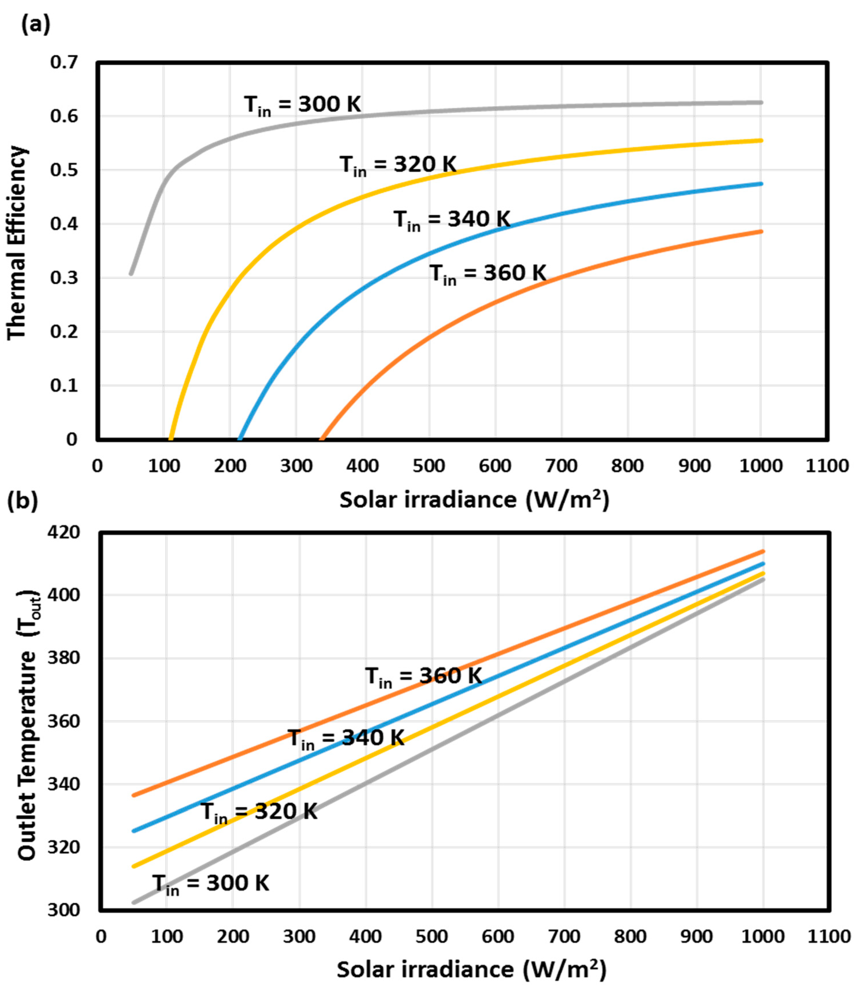
5.2. Effect of the Solar Irradiance

A research study was conducted to examine the effect of solar irradiation on the performance of an ETSC integrating a parabolic trough collector.
The impact of sunlight intensity on thermal efficiency under various inlet HTF temperatures—300 K, 320 K, 340 K, and 360 K—is presented in Figure 6a. The results show that the ETSC achieved a higher efficiency with a lower inlet HTF temperature and a higher solar intensity. The ETSC can generate hot water with a higher efficiency that reaches 61% by employing lower inlet HTF temperatures and higher solar radiation, while, by employing higher inlet HTF temperatures, its efficiency reaches 39%. Figure 6b depicts the profile of HTF outlet temperature under various inlet HTF temperatures. The results reveal that augmenting the solar intensity and the inlet HTF temperature increases the average outlet temperature of the HTF, which reaches a maximum of 418 K for an inlet HTF temperature of 360 K, while, at a lower inlet HTF temperature of 300 K, the outlet HTF temperature reaches 410 K. Similar results were found in our previous experimental study [42]. It was observed that increasing the solar intensity boosted the effectiveness of the ETSC, resulting in a higher water outlet temperature (40 °C). Hence, ETSC efficiency is significantly affected by increases in solar irradiance.

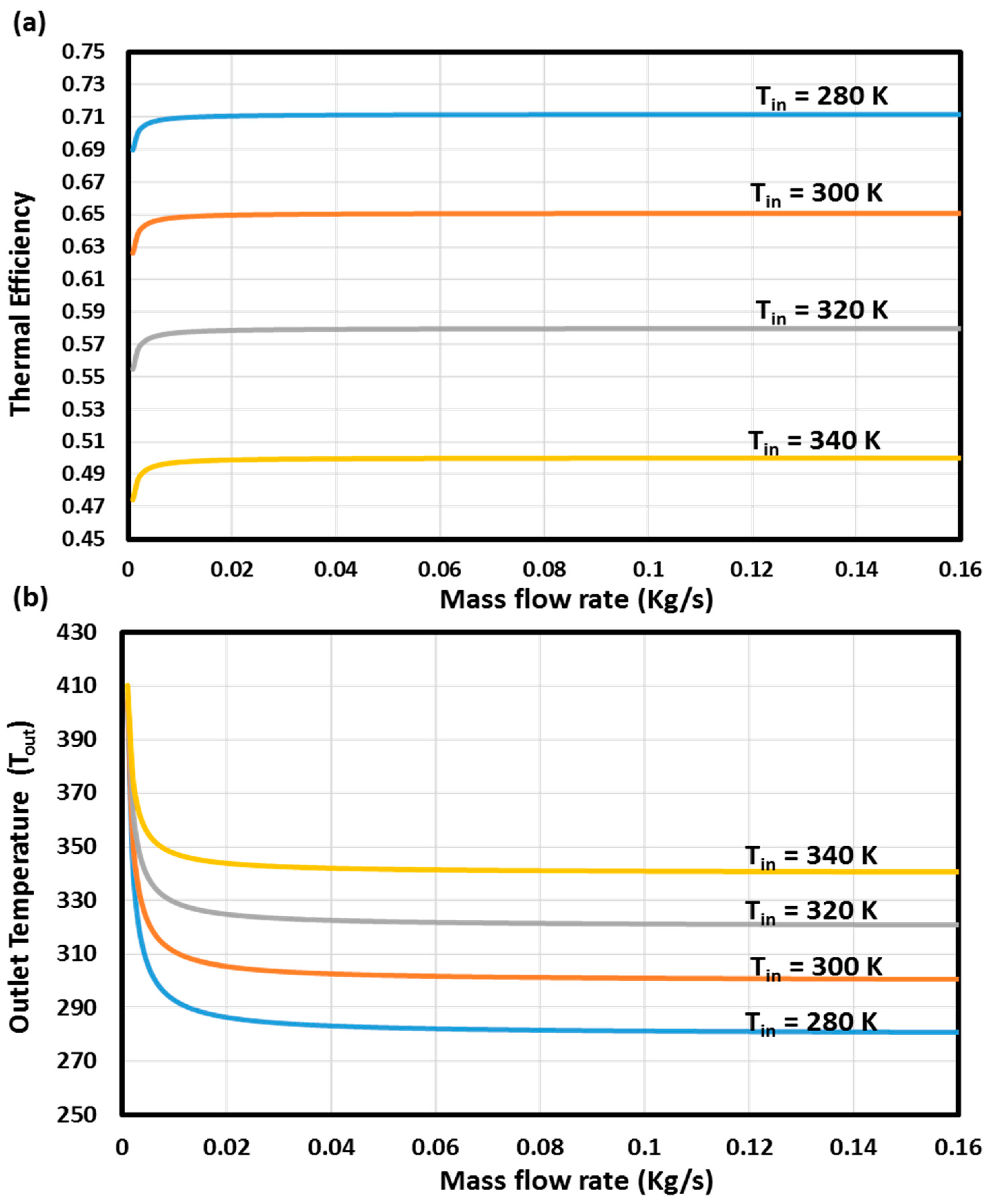
5.3. Effect of the Mass Flow Rate

The new model of evacuated tube solar collector was tested to study its productivity using different mass flow rates and different inlet HTF temperatures while maintaining a constant solar intensity (1000 W/m2).
Figure 7a displays the influence of HTF mass flow rate on ETSC effectiveness under various inlet HTF temperatures (280 K, 300 K, 320 K, and 340 K) with a constant solar irradiance (1000 W/m2). The results indicate that augmenting the mass flow rates leads to a slight rise in ETSC effectiveness, with a maximum of 72% while employing an inlet HTF temperature of 280 K and 49% with an inlet HTF temperature of 340 K.
The effect of water mass flow rate and inlet temperature on the profile of its outlet HTF temperature is illustrated in Figure 7b. The results indicate that as the water mass flow rate decreases, the outlet temperature rises to a peak of 410 K when employing a higher inlet HTF temperature of 340 K and reach a temperature of 400 K when employing a lower inlet HTF temperature of 280 K. Similar results were found in the experimental study of an ETSC with a heat pipe design integrated with PCM by Chopra et al. [43]. The experimental results demonstrate that while there is a decrease in the mass flow rate, the difference in temperature increases, and when using mass flow rates of 20 LPH, the system provides an effectiveness that reaches 87.8% and 55.46% with and without the use of PCM, respectively.

5.4. Effect of the Heat Transfer Coefficient

The ETSC system was tested to study the influence of the heat transfer coefficient on the performance of the ETSC by using different HTF inlet temperatures with a constant solar intensity of 1000 W/m2 and a constant mass flow rate of 0.001 Kg/s.
Figure 8a demonstrates how the heat transfer coefficient affects the ETSC’s effectiveness. The results indicate that employing a larger heat flow coefficient boosts the ETSC’s effectiveness by up to 75% at lower inlet water temperatures. However, when employing a higher inlet HTF temperature with a higher heat transfer coefficient, the effectiveness of the ETSC reaches 57%.
The impact of the heat transfer coefficient on the outlet HTF temperature is depicted in Figure 8b. The results demonstrate that increasing the heat transfer coefficient leads to a slight rise in outlet HTF temperature, with a maximum of 358 K when using a higher inlet HTF temperature and a maximum of 303 K when using an inlet HTF temperature of 280 K.

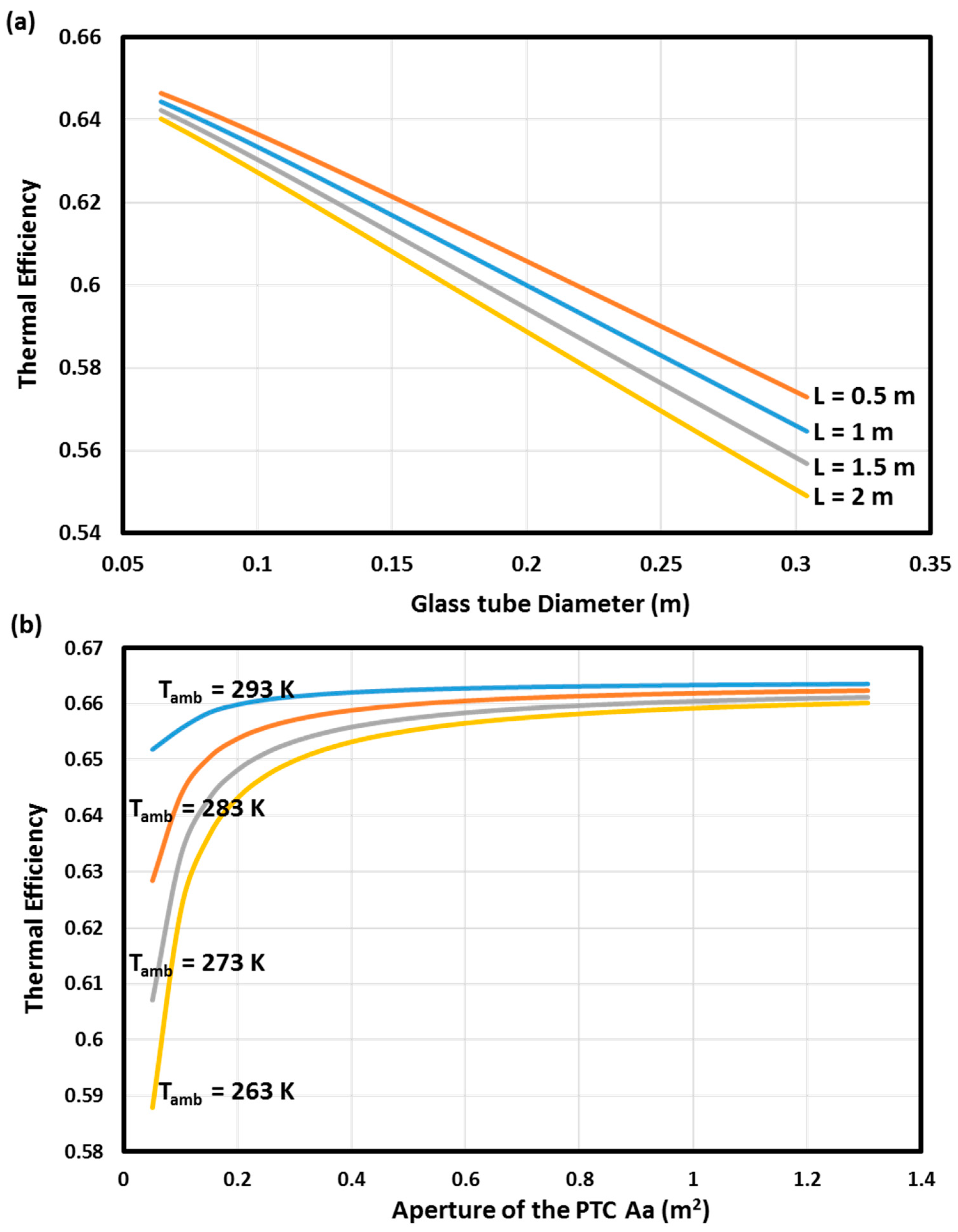
5.5. Effects of the Geometric Parameters

The aim of this study was to examine how different geometric parameters impact the effectiveness of an ETSC. Specifically, this part of the study sought to investigate the influence of the PTC aperture area, the ETSC length, and the glass tube inner diameter on an ETSC’s thermal efficiency. Figure 9a illustrates the impact of varying the glass tube inner diameter and ETSC length on thermal efficiency while using constant operational parameters such as a mass flow rate of 0.001 Kg/s, a solar intensity of 1000 w/m2, a heat transfer coefficient of 10 W/m2K, and an inlet HTF temperature of 300 K. The results show that efficiency increases as the tube diameter decreases. Moreover, a maximum thermal efficiency of 65% was obtained in the study when using a small tube length and diameter. However, as the tube length and diameter increase, the efficiency decreases, reaching a minimum of 54%.
The effects of varying the PTC aperture area on the effectiveness of the ETSC are displayed in Figure 9b. This part of the study was done under various ambient temperatures (263 K, 273 K, 283 K, and 293 K) with a constant glass tube inner diameter of 0.058 m and a constant ETSC length of 1 m. According to the results, with the increase in the aperture area and the rise in the ambient temperature, the thermal efficiency increased as well and reached 66%.
The maximum efficiency achieved in this study was 72% when employing the optimal parameters. Similar studies [42,44] have been conducted in order to evaluate the efficiency of the solar collector. In our previous article [42], a study was conducted to compare the performance of a heat pipe evacuated tube solar collector with four types of direct flow evacuated tube solar collectors (using a helical coil heat exchanger, U-tube heat exchanger, double U-tube heat exchanger, and coaxial tube heat exchanger). The results of this study showed that the highest efficiency achieved was 69% for the helical coil heat exchanger while the coaxial tubes, the double U-tubes, the U-tubes, and the heat pipes achieved efficiencies of 54% and 52%, 41%, and 31%, respectively. Siuta-Olcha et al. [44] conducted an analysis of an evacuated tube solar collector connected to a parabolic trough solar collector. The authors found that the maximum thermal efficiency is 24.1% for a 0.0082 kg/s mass flow rate.
An evacuated tube solar collector without a PTC receives only direct solar intensities. The presence of a PTC allows the evacuated tube solar collector to receive the maximum number of solar intensities, which increases its thermal efficiency and helps improve the system’s productivity. The flux distribution in the presence of a PTC enables more solar energy to be absorbed and converted into heat, leading to an increase in thermal efficiency. In the previous study [42], the maximum thermal efficiency was observed at 69% for an ETSC equipped with helical tubes and without the integration of a PTC. However, in the present study, the optimal thermal efficiency achieved was 72% with the integration of a PTC. These results indicate that the integration of a PTC significantly ameliorates the flux distribution within the solar collector, thereby improving its overall functionality.

6. Conclusions

An analytical model was created and studied in order to develop an innovative model of an evacuated tube solar collector equipped with a helical coil heat exchanger and integrated with a parabolic trough solar collector used for domestic water heating. The utilization of a helical coil heat exchanger in an ETSC offers several advantages such as the enhancement of thermal efficiency by improving heat transfer. Additionally, it has the ability to combine the transfer of thermal energy and storage functions into a single system. The helical tube design allows for a larger surface area for heat transfer, which increases the efficiency of the collector. A numerical study was conducted in order to investigate the optical behavior of a parabolic trough solar collector connected to a novel model of an ETSC using the Soltrace software. By using 2.5 million rays originating from a solar disk with a solar radiation of 1000 W/m2, the flux distribution over the ETSC presented an average flux of 13,059.8 W/m2 over the glass tube while the absorber tube exhibited an average flux of 13,441.7 W/m2. Moreover, a thermal performance assessment was conducted on the new model of an ETSC in order to investigate the effects of operational and geometric parameters on the productivity of the solar collector, leading to several conclusions:
-
The ETSC provided a higher HTF temperature (reaching 418 K) by employing higher solar intensities of 1000 W/m2 and using a 300 K inlet HTF temperature.
-
The ETSC system achieved an efficiency of 72% by employing an inlet HTF temperature of 280 K.
-
The new ETSC performs better by employing lower mass flow rates and higher heat transfer coefficients.
-
The use of a lower ETSC length and a lower diameter of the glass tube resulted in great performance with a maximum of 65%.
-
A large PTC aperture area also provides higher efficiency, which reaches 66%.
Overall, this work proposes an innovative approach by combining a helical coil heat exchanger and a parabolic trough solar collector in an ETSC used for domestic water heating. The findings emphasize the advantages of this novel design and provide valuable insights into the optimal operational and geometric parameters for improving the effectiveness and productivity of a solar collector.
Our actual work opens the path for future research and potential improvements in the field of ETSCs integrated with helical tubes. For future work, a numerical study will be undertaken to analyze the performance of an ETSC equipped with helical tubes and integrated with phase change materials. Additionally, a numerical study will be conducted to investigate the addition of metal fins to the system.

Author Contributions

Methodology, S.M. and R.A.; Software, S.S.; Formal analysis, S.M.; Investigation, S.A.; Project administration, T.A. All authors have read and agreed to the published version of the manuscript.

Funding

Deanship of Scientific Research at King Khalid University.

Institutional Review Board Statement

Not applicable

Informed Consent Statement

Not applicable.

Data Availability Statement

Not applicable.

Acknowledgments

The authors extend their appreciation to the Deanship of Scientific Research at King Khalid University for funding this work through the General Research Project under the grant number RGP.2/79/44.

Conflicts of Interest

The authors declare no conflict of interest.

Nomenclature

T i n Inlet temperature (K)
T o u t Outlet temperature (K)
T f m Mean fluid temperature (K)
T a m Ambient temperature (K)
T c Cover temperature (K)
G Solar beam radiation (W/m2)
m ˙ Mass flow rate (Kg/s)
C p Specific heat (J/Kg·K)
D r i Diameter of the absorber tube (m)
D Helical coil diameter (m)
d Outer diameter of the coil tube (m)
P Pitch of the helical coil tube (m)
h o u t Heat transfer coefficient between the cover and the atmosphere (W/m2·K)
h Heat transfer coefficient between the HTF and the absorber (W/m2·K)
λ Thermal conductivity (W/m·K)
A r o Area of the outer absorber tube (m2)
A c i Inner cover area (m2)
Q u Useful heat flow (W)
Q s Solar energy (W)
Q a b s Heat flow of the absorber tube (W)
Q l o s s Heat losses (W)
NuNusselt number
ReReynolds number
PrPrandtl number
Greek symbols
μ Dynamic viscosity (Kg/m·s)
ε r Emittance of the absorber tube
ε * Equivalent emittance
ε c Emittance of the cover
σ Stefan-Boltzmann constant (W/m2·K4)
η o p t Optical efficiency
η t h Thermal efficiency
Abbreviations
ETSCEvacuated tube solar collector
PTCParabolic trough collector
HTFHeat transfer fluid

References

  1. Jebasingh, V.; Herbert, G.J. A review of solar parabolic trough collector. Renew. Sustain. Energy Rev. 2016, 54, 1085–1091. [Google Scholar] [CrossRef]
  2. Panwar, N.L.; Kaushik, S.C.; Kothari, S. Role of renewable energy sources in environmental protection: A review. Renew. Sustain. Energy Rev. 2011, 15, 1513–1524. [Google Scholar] [CrossRef]
  3. Kannan, N.; Vakeesan, D. Solar energy for future world—A review. Renew. Sustain. Energy Rev. 2016, 62, 1092–1105. [Google Scholar] [CrossRef]
  4. Chopra, K.; Tyagi, V.; Pandey, A.; Sari, A. Global advancement on experimental and thermal analysis of evacuated tube collector with and without heat pipe systems and possible applications. Appl. Energy 2018, 228, 351–389. [Google Scholar] [CrossRef]
  5. Sabiha, M.A.; Saidur, R.; Mekhilef, S.; Mahian, O. Progress and latest developments of evacuated tube solar collectors. Renew. Sustain. Energy Rev. 2015, 51, 1038–1054. [Google Scholar] [CrossRef]
  6. Shafieian, A.; Khiadani, M.; Nosrati, A. A review of latest developments, progress, and applications of heat pipe solar collectors. Renew. Sustain. Energy Rev. 2018, 95, 273–304. [Google Scholar] [CrossRef]
  7. Priyanka, K.B. Thermal performance investigation of evacuated tube heat pipe solar collector integrated with parabolic Trough. IJARIIE 2017, 3, 2395–4396. [Google Scholar]
  8. Upadhyay, B.H.; Patel, A.J.; Ramana, P.V. A detailed review on solar parabolic trough collector. Int. J. Ambient. Energy 2019, 43, 176–196. [Google Scholar] [CrossRef]
  9. Odeh, S.D.; Abu-Mulaweh, H.I. Design and development of an educational solar tracking parabolic trough collector system. Glob. J. Eng. Educ. 2013, 15, 21–27. [Google Scholar]
  10. Abdulhamed, A.J.; Adam, N.M.; Ab-Kadir, M.Z.A.; Hairuddin, A.A. Review of solar parabolic-trough collector geometrical and thermal analyses, performance, and applications. Renew. Sustain. Energy Rev. 2018, 91, 822–831. [Google Scholar] [CrossRef]
  11. Haddock, C.; McKee, J.S.C. Solar energy collection, concentration, and thermal conversion—A review. Energy Sources 1991, 13, 461–482. [Google Scholar] [CrossRef]
  12. Hafez, A.; Attia, A.; Eltwab, H.; ElKousy, A.; Afifi, A.; AbdElhamid, A.; AbdElqader, A.; Fateen, S.-E.; El-Metwally, K.; Soliman, A.; et al. Design analysis of solar parabolic trough thermal collectors. Renew. Sustain. Energy Rev. 2018, 82, 1215–1260. [Google Scholar] [CrossRef]
  13. Fuqiang, W.; Ziming, C.; Jianyu, T.; Yuan, Y.; Yong, S.; Linhua, L. Progress in concentrated solar power technology with parabolic trough collector system: A comprehensive review. Renew. Sustain. Energy Rev. 2017, 79, 1314–1328. [Google Scholar] [CrossRef]
  14. Tagle-Salazar, P.D.; Nigam, K.D.P.; Rivera-Solorio, C.I. Parabolic trough solar collectors: A general overview of technology, industrial applications, energy market, modeling, and standards. Green Process. Synth. 2020, 9, 595–649. [Google Scholar] [CrossRef]
  15. Pandey, S.; Mishra, S.K.; Sharma, A.; Verma, A.K.; Yadav, L. Performance analysis of evacuated tube type solar air heater with parabolic trough type collector. Int. J. Energy Water Resour. 2021, 6, 337–351. [Google Scholar] [CrossRef]
  16. Tzivanidis, C.; Bellos, E.; Korres, D.; Antonopoulos, K.; Mitsopoulos, G. Thermal and optical efficiency investigation of a parabolic trough collector. Case Stud. Therm. Eng. 2015, 6, 226–237. [Google Scholar] [CrossRef] [Green Version]
  17. Elarem, R.; Alqahtani, T.; Mellouli, S.; Aich, W.; Ben Khedher, N.; Kolsi, L.; Jemni, A. Numerical study of an Evacuated Tube Solar Collector incorporating a Nano-PCM as a latent heat storage system. Case Stud. Therm. Eng. 2021, 24, 100859. [Google Scholar] [CrossRef]
  18. Bassem, S.; Jalil, J.M.; Ismael, S.J. Investigation of Thermal Performance of Evacuated Tube with Parabolic Trough Collector with and without Porous Media. IOP Conf. Ser. Earth Environ. Sci. 2022, 961, 012045. [Google Scholar] [CrossRef]
  19. Naik, B.K.; Premnath, S.; Muthukumar, P. Performance comparison of evacuated U-tube solar collector integrated parabolic reflector with conventional evacuated U-tube solar collector. Sādhanā 2021, 46, 137. [Google Scholar] [CrossRef]
  20. Abo-Elfadl, S.; Hassan, H.; El-Dosoky, M. Energy and exergy assessment of integrating reflectors on thermal energy storage of evacuated tube solar collector-heat pipe system. Sol. Energy 2020, 209, 470–484. [Google Scholar] [CrossRef]
  21. Rezaeian, M.; Dehaj, M.S.; Mohiabadi, M.Z.; Salarmofrad, M.; Shamsi, S. Experimental investigation into a parabolic solar collector with direct flow evacuated tube. Appl. Therm. Eng. 2021, 189, 116608. [Google Scholar] [CrossRef]
  22. Dawood, M.M.K.; Nabil, T.; Kabeel, A.; Shehata, A.I.; Abdalla, A.M.; Elnaghi, B.E. Experimental study of productivity progress for a solar still integrated with parabolic trough collectors with a phase change material in the receiver evacuated tubes and in the still. J. Energy Storage 2020, 32, 102007. [Google Scholar] [CrossRef]
  23. Shah, S.F.; Manzoor, S.; Mazoor, A.; Iqbal, A.; Asif, M.; Jafry, A.T. Modelling and Experimental Analysis of a Novel Evacuated Tubes based Parabolic Trough Solar Collector for Water Heating Applications. In Proceedings of the 2021 International Conference on Emerging Power Technologies (ICEPT), Topi, Pakistan, 10–11 April 2021. [Google Scholar] [CrossRef]
  24. Fathabadi, H. Impact of utilizing reflector, single-axis and two-axis sun trackers on the performance of an evacuated tube solar collector. Int. J. Green Energy 2020, 17, 742–755. [Google Scholar] [CrossRef]
  25. Feliński, P.; Sekret, R. Effect of a low cost parabolic reflector on the charging efficiency of an evacuated tube collector/storage system with a PCM. Sol. Energy 2017, 144, 758–766. [Google Scholar] [CrossRef]
  26. Nabil, T.; Dawood, M.M.K. Numerical and experimental investigation of parabolic trough collector with focal evacuated tube and different working fluids integrated with single slope solar still. Heat Transf. 2020, 50, 2007–2032. [Google Scholar] [CrossRef]
  27. Xu, L.; Wang, Z.; Yuan, G.; Li, X.; Ruan, Y. A new dynamic test method for thermal performance of all-glass evacuated solar air collectors. Sol. Energy 2012, 86, 1222–1231. [Google Scholar] [CrossRef]
  28. Bellos, E.; Tzivanidis, C.; Antonopoulos, K.A.; Daniil, I. The use of gas working fluids in parabolic trough collectors—An energetic and exergetic analysis. Appl. Therm. Eng. 2016, 109, 1–14. [Google Scholar] [CrossRef]
  29. Bellos, E.; Tzivanidis, C. Assessment of the thermal enhancement methods in parabolic trough collectors. Int. J. Energy Environ. Eng. 2017, 9, 59–70. [Google Scholar] [CrossRef] [Green Version]
  30. Bellos, E.; Tzivanidis, C.; Antonopoulos, K.A. A detailed working fluid investigation for solar parabolic trough collectors. Appl. Therm. Eng. 2016, 114, 374–386. [Google Scholar] [CrossRef]
  31. Abed, N.; Afgan, I. An extensive review of various technologies for enhancing the thermal and optical performances of parabolic trough collectors. Int. J. Energy Res. 2020, 44, 5117–5164. [Google Scholar] [CrossRef] [Green Version]
  32. Bellos, E.; Tzivanidis, C. Analytical Expression of Parabolic Trough Solar Collector Performance. Designs 2018, 2, 9. [Google Scholar] [CrossRef] [Green Version]
  33. Ma, L.; Lu, Z.; Zhang, J.; Liang, R. Thermal performance analysis of the glass evacuated tube solar collector with U-tube. Build. Environ. 2010, 45, 1959–1967. [Google Scholar] [CrossRef]
  34. Mangal, D.; Lamba, D.K.; Gupta, T.; Jhamb, K. Acknowledgement of Evacuated Tube Solar Water Heater Over Flat Plate Solar Water Heater. Int. J. Eng. 2010, 4, 279–284. [Google Scholar]
  35. Mahdi, Q.S.; Fattah, S.A.; juma Abd, F. Experimental and Numerical Investigation to Evaluate the Performance of Helical Coiled Tube Heat Exchanger. J. Eng. Dev. 2014, 18, 89–110. [Google Scholar]
  36. Moawed, M. Experimental study of forced convection from helical coiled tubes with different parameters. Energy Convers. Manag. 2011, 52, 1150–1156. [Google Scholar] [CrossRef]
  37. Riyandwita, B.W.; Awwaluddin, M.; Hastuty, S. Performance evaluation of helical coil heat exchanger with annulus shell side using computational fluid dynamics. AIP Conf. Proc. 2019, 2180, 020039. [Google Scholar] [CrossRef]
  38. Liu, X.; Huang, J.; Mao, Q. Sensitive Analysis for the Efficiency of a Parabolic Trough Solar Collector Based on Orthogonal Experiment. Int. J. Photoenergy 2015, 2015, 151874. [Google Scholar] [CrossRef] [Green Version]
  39. Macedo-Valencia, J.; Ramírez-Ávila, J.; Acosta, R.; Jaramillo, O.; Aguilar, J. Design, Construction and Evaluation of Parabolic Trough Collector as Demonstrative Prototype. Energy Procedia 2014, 57, 989–998. [Google Scholar] [CrossRef] [Green Version]
  40. Sharma, A.; Lohani, R.B. Sensitivity Analysis of Parabolic Trough Collector in SolTrace. In Proceedings of the 2019 IEEE 1st International Conference on Energy, Systems and Information Processing (ICESIP), Chennai, India, 4–6 July 2019; pp. 1–6. [Google Scholar] [CrossRef]
  41. Cheng, Z.D.; He, Y.L.; Cui, F.Q.; Du, B.C.; Zheng, Z.J.; Xu, Y. Comparative and Sensitive Analysis for Parabolic Trough Solar Collectors with A DetailedMonte Carlo Ray-Tracing Optical Model. Appl. Energy 2014, 115, 559–572. [Google Scholar] [CrossRef]
  42. Said, S.; Mellouli, S.; Alqahtani, T.; Algarni, S.; Ajjel, R.; Ghachem, K. An Experimental Comparison of the Performance of Various Evacuated Tube Solar Collector Designs. Sustainability 2023, 15, 5533. [Google Scholar] [CrossRef]
  43. Chopra, K.; Pathak, A.K.; Tyagi, V.; Pandey, A.; Anand, S.; Sari, A. Thermal performance of phase change material integrated heat pipe evacuated tube solar collector system: An experimental assessment. Energy Convers. Manag. 2019, 203, 112205. [Google Scholar] [CrossRef]
  44. Siuta-Olcha, A.; Cholewa, T.; Dopieralska-Howoruszko, K. Experimental studies of thermal performance of an evacuated tube heat pipe solar collector in Polish climatic conditions. Environ. Sci. Pollut. Res. 2020, 28, 14319–14328. [Google Scholar] [CrossRef] [PubMed] [Green Version]
Figure 1. Configuration of the ETSC employing a parabolic trough collector and a helical coil heat exchanger.
Sustainability 15 11497 g001
Figure 2. Parabola reflector design using Parabola Calculator 2.0.
Sustainability 15 11497 g002
Figure 3. Side view of rays’ intersection with the solar collector: (a) rays from 1–100 and (b) rays from 1–200.
Sustainability 15 11497 g003
Figure 4. Close view of the evacuated tube solar collector: (a) evacuated tube (b) intersection of solar rays with ETSC.
Sustainability 15 11497 g004
Figure 5. Flux distribution over the absorber tube: (a) contour plot and (b) surface plot.
Sustainability 15 11497 g005
Figure 6. Effect of solar irradiance on (a) thermal efficiency and (b) outlet HTF temperature.
Sustainability 15 11497 g006
Figure 7. Effect of mass flow rate on (a) thermal efficiency and (b) outlet temperature.
Sustainability 15 11497 g007
Figure 8. Effect of the heat transfer coefficient on (a) thermal efficiency and (b) outlet temperature.
Sustainability 15 11497 g008
Figure 9. Effect of (a) the glass tube inner dimeter and (b) the aperture of the PTC on thermal efficiency.
Sustainability 15 11497 g009
Table 1. The geometric parameters of the solar collector.
Parabolic trough Solar CollectorEvacuated Tube Solar Collector
Focal length (mm)100.01Glass diameter (mm)58
Diameter (mm)253Inner pipe diameter (mm)54
Depth (mm)40Length (mm)700
Length (mm)700
Rim angle60°
Table 2. Optical properties of the solar collector [40].
PTCGlass TubeAbsorber Tube
Reflectivity0.9600.96
Refraction110.1
Transmissivity0.950.951
Slope error (mrad) 30.00010.0001
Speculiarity error (mrad)0.50.00010.0001
Disclaimer/Publisher’s Note: The statements, opinions and data contained in all publications are solely those of the individual author(s) and contributor(s) and not of MDPI and/or the editor(s). MDPI and/or the editor(s) disclaim responsibility for any injury to people or property resulting from any ideas, methods, instructions or products referred to in the content.

