

Use of Waste Tires as Transverse Reinforcement and External Confinement in Concrete Columns Subjected to Axial Loads


1
Blue Planet Systems, Los Gatos, CA 95032, USA
2
Department of Civil & Environmental Engineering, Idaho State University, Pocatello, ID 83209, USA
*
Author to whom correspondence should be addressed.
Sustainability 2023, 15(15), 11620; https://doi.org/10.3390/su151511620
Submission received: 1 June 2023
/
Revised: 30 June 2023
/
Accepted: 8 July 2023
/
Published: 27 July 2023
(This article belongs to the Special Issue Advanced Concrete and Construction Materials)
Abstract
:Approximately 246 million waste tires are generated annually in the United States. That is roughly three tires per four individuals in the country. Most tires end up in landfills, adversely affecting the environment. In the last two decades, researchers have explored using tire chips in concrete to replace a portion of coarse aggregates. Past studies have indicated that up to 50% of coarse aggregates in concrete can be replaced with tire chips. This research proposes using recycled rubber tires and rubber chips in concrete columns. The tires are used as external transverse reinforcement in plain concrete columns. The tires function as formwork during the pour while providing confinement after curing. The concepts in this research can be used for retrofitting structures with inadequate foundations and constructing new structures. After analyzing the data from this research, the axial compressive test of confined columns was 50% greater on average than unconfined columns. The confinement effectiveness ratio for all confined specimens was greater than one.
1. Introduction
Concrete is one of the world’s oldest building materials [1]. The design community constantly offers new ideas and methods to find alternative materials to make concrete inexpensive or more sustainable than it already is by reducing its carbon footprint. New additives for concrete mixtures are also being researched and produced regularly. Cementitious materials such as fly ash, slag, silica fumes, and waste materials such as crumbled rubber are used as filler for cement or as a replacement for aggregate in concrete. In this research, waste tires have been recycled and used as reinforcement for the concrete column. Approximately 246 million waste tires are generated annually in the United States [2,3]. That is roughly three tires per four individuals in the country. Most tires end up in landfills, adversely affecting the environment. Using scrap tire rubber in making concrete has been proposed as an environmentally friendly alternative to disposing of such waste [4,5].
Studies have demonstrated that rubber tires contain elements that do not disintegrate, posing a threat to the environment [6]. The hazardous chemical produced by scrap tires at junkyards and landfills impact the environment [7]. Obtaining the most efficient methods of recycling old tires helps to conserve the environment [8]. Energy recovery is a widespread practice for managing waste tires. Entire or partial tires are an alternative fuel in power plants, paper mills, and cement kilns. According to the most recent statistical report on the management of end-of-life tires released by ETRMA, approximately 91% of waste tires in the nations of the European Union, as well as Norway, Serbia, Switzerland, and Turkey, were properly collected and managed in 2018 through material recycling (56.4%) and energy recovery (34.9%) [9]. As a result, studies have investigated techniques to recycle scrap tires that are both ecologically benign and cost-effective [3,4]. Because tire production is continually expanding, appropriate recycling of old tires is one of the most pressing concerns in the twenty-first century. Adequate tire management has necessitated the adoption of innovative technologies that improve recycling [8,10]. Improving recycling methods would aid in resolving the environmental issue posed by automobile tires.
1.1. Literature Review
Researchers have investigated the possibility of using rubber in various civil engineering projects for decades. Dabri et al. conducted an analytical investigation on the seismic behavior of reinforced concrete piers using elastomeric materials, while Jia et al. examined the seismic evaluation of precast bridge columns incorporating built-in elastomeric pads [11,12]. Additionally, the use of tire rubber in applications such as cement mixtures, road construction, and geotechnical work has been demonstrated to be effective in environmental protection and natural resource conservation, making it a suitable disposal method considering both environmental and economic factors [13,14]. Incorporating recycled tire aggregate in concrete enhances deformability, energy dissipation, and damping. However, an increased concentration of rubber in the concrete leads to reduced compressive and tensile strengths and a diminished Young’s modulus of elasticity [15].
Consequently, incorporating rubber aggregates as partial replacements for fine or coarse aggregates primarily compromises the compressive strength of the mixture [2,3,5,6,15,16,17,18,19]. Studies have shown significant reductions in compressive strength, up to 60%, when replacing 50% of the coarse aggregate with rubber crumbs [20]. A study involving 70 concrete samples demonstrated that increasing rubber content decreased strength and modulus. Nevertheless, the addition of silica fume improved properties and mitigated strength loss. The research suggested that up to 25% rubber contents could produce rubberized concretes with compressive strengths ranging from 16 to 32 MPa [21].
This research investigates the utilization of 15% rubber aggregate by volume as a replacement for coarse aggregate and incorporating waste tires as transverse reinforcement in concrete columns. Columns play a critical role in ensuring the structural integrity of buildings by bearing significant loads and transmitting them to the foundation. Both strength and ductility are equally essential considerations in column design [22]. To enhance the characteristics of concrete structural elements, concrete confinement techniques have been employed in beams, slabs, columns, and walls to strengthen existing structures, adapt them, or construct new ones [23]. It has been demonstrated that confinement significantly improves concrete performance [24].
Researchers have explored various methods of confinement in concrete structures. Abdullah et al. conducted a study using four normal reinforced concrete (R.C.) beams, demonstrating that the application of post-tensioned metal straps (PTMS) around the beams’ tensile zone increased their load-carrying capacity by 36% to 39% [25]. Garcia et al. proposed an innovative dual retrofitting system that combined Carbon Fiber Reinforced Polymers (CFRP) with PTMS applied to opposing frames of a building [26]. This retrofitting approach enabled the structure to withstand peak ground acceleration (PGA) up to four times higher than the original building [26]. Imjai et al. conducted a comprehensive analysis of multiple studies, concluding that PTMS effectively enhances the capacity and ductility of reinforced concrete elements under compression, shear, flexure, and bond-splitting-dominated conditions [27]. Ma et al. conducted tests on 24 cylinders under axial compression, revealing that the implementation of post-tensioned steel straps increased the strength of pre-damaged specimens by 313% and the axial deformability of pre-damaged cylinders by 2.64–2.95% [28]. Similarly, Imjai et al. performed an analytical and experimental study on four concrete beams to investigate the capacity enhancement of pre-cracked Side-Near Surface Mounted (SNSM) strengthened beams, resulting in a capacity increase of up to 55%. In contrast, beams strengthened with PTMS exhibited a capacity increase of only 8%, indicating that the former benefited from additional flexural reinforcement provided by CFRP bars [29].
The choice of confinement material significantly influences confined concrete’s load paths and deformation behavior. Different materials, such as steel hoops or stirrups, FRP, and GFRP, exhibit diverse load-deformation properties, leading to variations in concrete performance [30]. As a result, the selection of the confinement material has a substantial impact on the behavior of concrete. Mander et al. developed a unified stress-strain approach (Figure 1) specifically designed for circular transverse reinforcement in confined concrete [31].
The confining material creates tensile hoop stress balanced by a uniform radial pressure, which responds to the concrete’s lateral expansion as the axial stress grows, increasing the corresponding lateral strain [32,33]. Figure 2 shows the hoop tension developed by transverse steel reinforcements at yield and lateral stress on the concrete core. Equation (1) provides the expression for the confining pressure (fl) at force equilibrium.
- fyh is the yield stress of the confining spirals, MPa
- Ssp is the pitch of the confining spirals, mm
- ds is the diameter of spirals between bar centers, mm.
Concrete expands laterally when an enclosed column is subjected to axial compression, but confining media constraints such expansion. Confinement effectiveness is a metric used to assess how successfully a material confines concrete, that is f′cc/′co, where f′cc is the compressive strength of confined concrete and f′co is the compressive strength of unconfined concrete.
The composition of tires can be seen in Figure 3, and tires are made using different materials in layers, as shown in Figure 4.
Steel wire is used in tire belts, beads, and truck tire plies. The belts beneath the tread stiffen the tire casing, improving wear performance and handling. Polyester cord fabrics, rayon cord fabrics, nylon cord fabrics, and aramid cord fabrics are textiles used as reinforcing materials in tires. This steel wire and textiles in tires make them desirable for reinforcements. Tires can be used as external reinforcements around concrete columns and act as formworks for the columns. The reinforcement has been assumed to be similar to that created using circular hoops or stirrups. This assumption is made as an approximation to find out the confinement provided by tires. The axial compressive strength and confinement by tires were investigated in this study.
1.2. Problem Statement
The increasing production of vehicles has led to a rise in worn-out tires, posing significant risks to the environment and public health [8]. Improper recycling practices result in the loss of the economic value of tires and contribute to wasteful land usage. Moreover, disposing of waste tires often incurs additional charges. Therefore, it is crucial to understand the necessary steps for improving standards. As the demand for concrete reinforcement grows in the construction industry, tires can offer a valuable solution. By incorporating waste rubber scraps into concrete, both spaces can be saved, and the environment can be improved. Recycling vehicle tires through concrete reinforcement benefits the building sector financially, as materials that would have otherwise been discarded in landfills or junkyards are utilized. Utilizing scrap tire chunks or whole tires in construction promotes tire recycling. Rubber is more reusable than other building materials, creating a cleaner and more sustainable environment.
In this study, the authors propose an innovative approach of using recycled tires as external confinement to enhance concrete strength and deformation capacity under axial loads. The tires serve a similar function as stirrups or ties in concrete columns. To validate this concept, full-scale concrete pedestals are subjected to axial tests. These columns are constructed using plain rubber concrete with and without external tires. The results obtained from the confined columns are compared to those of unconfined (benchmark) specimens.
2. Experimental Works
2.1. Material and Specimens Specification
Two methods of utilizing waste tires have been used in this research. Method 1 involves utilizing waste tires, which have been shredded into small chunks and are used as a replacement for coarse aggregate. Method 2 reuses the whole tire with transverse reinforcement to provide confinement to the concrete columns.
It is important to note that specimens were not reinforced with steel bars. It is so because we are not investigating the effects of rebar in the concrete. The scope of the research is to see if tires can provide confinement without reinforcing. Adding reinforcing would bring other parameters into play (e.g., reinforcing ratio, volumetric transverse reinforcing, etc.). This would make the comparison more complicated in differentiating how much confinement each (tire and stirrups) can provide. Since the research is just looking at the compressive strength, smaller specimens would be sufficient; however, it is very difficult to obtain the smaller tires.
Twelve specimens of concrete columns were made; two with regular concrete, two with rubber concrete, four with regular concrete confined with tires, and four with rubber concrete confined with tires. The dimensions of the eight unconfined columns were 0.406 m (16 inches) in diameter and 0.914 m (36 inches) in height, and those for the confined columns were 0.762 ± 0.02 m (30 ± 0.75 inches) in diameter and 0.914 ± 0.006 m (36 ± 0.25 inches) in height. The tires utilized in this research were exclusively 16-inch rim diameter tires, readily accessible in tire shops near Idaho State University. The variation in diameter observed among the confined columns can be attributed to the utilization of different tires, each with its distinct level of wear and tear. The height measurement of each tire employed was 0.229 ± 0.013 m (9.0 ± 0.5 inches), as documented in Figure 5, which presents the tire dimensions. It is important to note that unconfined columns are not fabricated with the same diameter as the confined columns. If the amount of concrete in the unconfined columns is the same as in confined columns, then the comparison would not be easier. Also, the scrap tires have different diameters, so some were cut on one side along the height to have that consistent diameter for better comparison. Most tires used were classified as all-season tires, while a smaller portion consisted of winter and summer tires. Most tires featured steel cord belts with nylon ply as their casing material, while the sidewalls were reinforced with steel wire beads. Additionally, it is worth noting that the thread pattern varied among different tire brands.
For rubber concrete, 15% of the volume of course aggregate is replaced by rubber aggregate. To have a similar strength, the quantity of cement was increased to 520.6 kg./cu. m and fly ash was decreased to 130 kg./cu. m. The rubber aggregate used was 19 mm or smaller. The mix design for the normal and rubberized concrete is given in Table 1.
2.2. Construction
The unconfined columns (UC) were constructed using sonotubes, with wooden formwork employed to support them, as illustrated in Figure 6. To prevent any leakage during the pouring process, the lower ends of the sonotubes were caulked. Four tires were stacked together for the tire columns (TC), and three threaded rods were inserted into each tire to prevent collapse, as depicted in Figure 7. The top of each tire was drilled to avoid the entrapment of air bubbles. Initially, the tires were joined together using four three-inch screws, and the connection between the tires was sealed with epoxy to prevent any concrete leakage during pouring. The complete set of test specimens was prepared and poured exclusively within the research laboratory of ISU. The concrete mixer employed for this purpose was a 12-cubic-ft drum mixer. During the pouring process, the specimens underwent three layers of vibration. Once the columns were poured, steps were taken to level and smooth the top surface using a smooth trough. To ensure optimal curing conditions, the specimens were carefully wrapped with wet burlap and securely covered with a plastic tarp, preventing any loss of moisture. In accordance with the guidelines specified in ASTM C31-19 [36], three standard compression cylinders were randomly prepared for each test specimen. These cylinders were then placed in a concrete bath tank and underwent the curing process at laboratory temperature. After a curing period of 28 days, the compressive strength of the sample cylinders was evaluated through testing. The average compressive strength of each configuration specimen can be found in Table 2.
2.3. Instrumentation and Test Setup
The Campbell Scientific data acquisition system (DAQ) was used to simultaneously monitor and record the loads and the axial deflections during the tests. The data collection rate for the test was set at two data points per second. The loads were recorded using a 2500-kips capacity load cell attached to the top of the isolation frame. The axial deflections of the specimen were measured using two 50-inch stroke string potentiometers placed at the centerline of the loading plates and attached at the edge. Four-string potentiometers were mounted on top of the isolation frame to measure the deflection of the top beam during the test. Eight potentiometers were used to measure the deflection of the vertical columns.
The monotonic compressive testing follows ASTM C39-21 [37], with a minor difference in that the height-to-diameter ratio is slightly greater than 2.2. That is due to the recyclable tires available affecting the height. The testing was performed using an isolation frame setup shown in Figure 8. The hydraulic jack can reach up to 8900 kN force with a maximum stroke of 4 inches. The load from the hydraulic jack was then transferred to a 16-inch diameter steel plate to distribute the axial load uniformly across the ends of the columns. The loading plates were used to have similar loading for all specimens. The loading apparatus was the same for tire columns. The tire columns had a diameter of around 30 inches, but the loading area was only 16 inches.
A monotonic quasi-static loading protocol in accordance with ASTM C39-21 [37] was used to load the specimen for this test. The loading for the compression tests was applied at an increment of around 1500 pounds per second and continued until failure. For the unconfined columns, the tests were continued until the failure of the specimen. For tire columns, the loading continued until either the tires ruptured or there was a significant drop in axial load. The axial force and displacement were recorded for each specimen from the load cell and string potentiometers.
2.4. Experimental Results
For the test, six different configurations were used:
- (a)
- Two unconfined columns with normal concrete (UCNCs),
- (b)
- Two unconfined columns with rubberized concrete (UCRCs),
- (c)
- Two confined columns with normal concrete (CCNCs),
- (d)
- Two confined columns with rubberized concrete (CCRCs),
- (e)
- Two confined columns with normal concrete with tires cut along the height (CCNCHs),
- (f)
- Two confined columns with rubberized concrete with tires cut along the height (CCRCHs).
The results from each configuration have been compared with results from other configurations. The main parameters compared were the peak force, peak displacement, peak stress, peak strain, and energy dissipation. A force-controlled testing method was used in this study. The inconsistency in the graph is due to the force-controlled testing method. The data from the table for peak force and displacement are more relevant in this type of test. Other plots and comparisons, such as energy dissipated before failure, may change depending on the type of test, such as force based vs. displacement-based or monotonic vs. cyclic test. Figure 9 illustrates the axial force versus displacement plot for the tested specimens.
The 28-day compressive strength of the unconfined normal concrete cylinder was 35.2 MPa, surpassing the strength of the UCNC1 and UCNC2 specimens. This suggests that the full-scale columns experienced non-uniform loading due to using steel plates instead of rubber or wood caps. Similarly, the UCRC1 and UCRC2 specimens displayed a lower cylinder compressive strength at 34.8 MPa, indicating non-uniform loading. Furthermore, all of these specimens exhibited a brittle failure pattern.
On the other hand, the CCNC, CCRC, CCNCH, and CCRCH columns were effectively confined using four tires with a diameter of 0.762 m and a limited loading surface area of 0.406 m. The 28-day compressive strengths of the concrete cylinder samples were measured at 35.1 kN for CCNC, 34.9 kN for CCRC, 35.1 kN for CCNCH, and 34.9 MPa for CCRCH. The increase in axial compressive strength suggests that the tires provided a level of confinement for the columns.
The compressive strength of CCNC1 was 32% higher than the sample, while CCNC2 showed a 12% increase. The columns experienced maximum force and subsequent decline, indicating concrete failure. Tire reinforcement became effective after concrete failure, with significant drops in axial force. In CCNC1, tire reinforcement started after a 7% force reduction, followed by a 2% increase and tire spitting. CCNC2 had a 23% force reduction, followed by force fluctuations until tire splitting. CCRC1 exhibited a 23% force drop, while CCRC2 had a 37% force reduction, with subsequent force fluctuations. CCNCH1 experienced a 57% force drop, picked up force by 58%, and fell again. CCNCH2 had a 37% force reduction, picking up force briefly before a significant dropping. CCRCH1 had a 64% force drop, followed by force fluctuations, while CCRCH2 had a 37% force reduction, a 22% drop, and significant force fluctuations. Concrete cracks produced audible popping sounds but remained hidden due to tire confinement.
After the failure of CCNC1, a 304 mm diagonal split occurred in the second tire from the top, with only a hairline crack visible in the exposed concrete. CCNC2 had an approximately 50.8 mm crack in the exposed concrete at the tire split, and the tire connection appeared lifted by the failed concrete. CCRC1 tilted to one side after failure, with a failed tire at the bottom and 50.8 mm cracks in the exposed concrete. CCRC2 exhibited a 100 mm crack on the exposed concrete at the tire split, and the top surface had a rupture on the tire sidewall, unique among columns. CCNCH1 had approximately 25.4 mm cracks in the exposed concrete, while CCNCH2 had a 12.7 mm crack at the tire split. Both failed from the section where the tire split. CCRCH1 had an 88.9 mm crack on the exposed concrete, while CCRCH2 had a 63.5 mm crack at the tire split. Popping sounds accompanied the concrete cracking, and force reduction was observed with each sound.
Figure 10, Figure 11, Figure 12, Figure 13, Figure 14 and Figure 15 illustrate the failure modes of the UCNC, UCRC, CCNC, CCRC, CCNCH, and CCRCH specimens. Similarly, all samples’ performance factors (e.g., maximum axial force, corresponding displacement, maximum stress, corresponding strain, and energy dissipation) are summarized in Table 3.
2.4.1. Unconfined Concrete Column: Normal Concrete vs. Rubberized Concrete
Four specimens with these configurations (i.e., two of each—UCNC and UCRC) were tested. The plot (Figure 16) shows the combined data from each configuration and graph. It is evident from the plot that the columns with rubber aggregate underwent greater axial deformation than the normal concrete columns. The axial strain of the UCRCs was 40% higher than that of the UCNCs on average. UCNC specimens failed in a brittle manner with visible cracks, indicating shear or conical failure. UCRC specimens also failed in a brittle manner, accompanied by a popping sound and columnar failure. Crack size was not measured for safety reasons. Thus, the failure modes for both configurations were similar: shear and columnar failure. The peak stress values were close to each other. The failure is brittle, but compared to this configuration, the rubber concrete had a higher strain at the point of failure. UCRCs can disperse more energy from monotonic compression loading than UCNCs. Based on these results, rubberized concrete will have less damage than columns with normal concrete under similar loading conditions.
2.4.2. Confined Concrete Column: Normal Concrete vs. Rubberized Concrete
Four specimens were tested from these configurations, two CCNC and CCRC specimens. The force vs. displacement graph in Figure 17 shows the combined data for each configuration. Each specimen was loaded until the tire failure was externally observed or until the specimen kept picking up force after a sudden drop in the force due to the failure of the concrete. Here, the concrete axial force that the column reached before the concrete failed was higher than that for the UCs. The columns reached a peak force. Then the force dropped by 15% on average in the CCNCs and around 30% in the CCRCs. Beyond this point, columns in both configurations showed strain-softening behavior. The CCRCs had 46% more axial strain on average but lower stress at the point of concrete failure. In both cases, the columns continued to pick up force until the sudden drop but never reached the previous peak force. As shown in the plot, the columns stopped picking up force after the tires ruptured. The average strain at the point of failure for a column with rubber aggregate was higher. The energy dissipation of the CCNCs was almost double that of the CCRCs. This means CCNCs can disperse more energy from monotonic compression loading than CCRCs. These results show that confined columns with normal concrete will have less damage than columns with rubberized concrete under similar loading conditions. The variation in energy dissipation might be due to different tires and different wear and tear on them. The sample size of columns tested in these configurations is small, so further investigation is needed to verify these results.
2.4.3. Confined Concrete Columns with Tires Cut along the Height: Normal Concrete vs. Rubberized Concrete
Four specimens were tested from these configurations, two CCNCH and CCRCH specimens. The force vs. displacement graph is shown in Figure 18 for the combined data of each configuration. The pattern of the force and displacement is similar to confined. Still, the force reduction in these columns after concrete failure was considerably higher than in the confined column without tire cuts. The average drop in force for the CCNCHs was almost 47%, and that for the CCRCHs was around 50%. The peak stress and corresponding strain are significantly higher for columns with normal concrete. The average peak stress for the CCNCHs was 19% higher than that for the CCRCHs. The average corresponding strain for the CCNCHs was 50% higher than that for the CCRCHs. Variables such as different tires and varying wear and tear patterns might have influenced this. As mentioned earlier, the testing was force-controlled and is one of the reasons for the inconsistency in the plots. Axial deformation and energy dissipated before failure. CCNCH’s energy dissipation is more than three times that of CCRCHs. This means CCNCH can disperse more energy from monotonic compression loading than CCRCH. Based on these results, CCNCHs will have less damage than CCRCHs under similar loading conditions. The sample size of columns tested in these configurations is small, so further investigation is needed to verify these results.
2.4.4. Normal Concrete Columns Comparison
This section compares the concrete properties of normal concrete when it is unconfined, confined, and confined with a height cut. Before the concrete fails, there is a significant increase in axial force, nearly 80%, in the confined column compared to the unconfined column. The axial force capacities of CCNCs and CCNCHs are just 7% higher than that of UCNCs. There is a significant drop in force in CCNCHs once the concrete begins to fail. On average, the force drop is 15% for CCNCs, while that for CCNCHs is 47%. This shows that the tires reinforce both columns, but the tires in the CCNCHs were cut along the height, so the overall confinement effect is lower. The average rise in force capacity after the drop from peak force was 5% for CCNCs, and that for CCNCH was 35%. This shows that the reinforcement by tires starts after the concrete fails. The average axial strain corresponding to peak stress for the CCNCs was 39% higher than that for the UCNCs and 4% higher than that for the CCNCHs. Figure 19 shows the compressive force and displacement difference between confined and unconfined columns with normal concrete. The energy dissipation is more than eight times higher in CCNCs than UCNCs and almost six times higher in CCNCHs. The significant increase in energy dissipation shows that the tires acted as reinforcements for the columns. CCNCs can disperse more energy from monotonic compression loading than UCNCs. These results indicate that confined columns with normal concrete will undergo lesser damage than unconfined columns under similar loading conditions.
2.4.5. Rubberized Concrete Columns Comparison
The concrete properties of rubberized concrete when it is unconfined, confined, and confined with a height cut have been compared in this section. Before concrete fails, there is a significant increase of nearly 25% in axial force in the confined column compared to the unconfined column. The axial force capacities of CCRCs and CCRCHs are similar. There is a significant drop in force in CCRCHs once the concrete begins to fail. On average, the force drop is 30% for CCRCs, while that for CCRCHs is 51%. This shows that the tires reinforced both columns, but for CCRCHs, the tires were cut along the height, so the overall confining effect is lower. The average rise in force capacity after the drop from the peak force was 13% for the CCRCs, and that for the CCRCH was 40%. This shows that the reinforcement effect of the tires engages after the concrete fails. The average axial strain on CCRCs corresponding to peak stress is twice that of UCRCs and is almost four times higher than that of CCRCHs. The concrete undergoes brittle failure when unconfined but undergoes significant deformation before failure when it is confined with tires. Figure 20 shows the compressive force and displacement difference between confined columns and unconfined columns with rubberized concrete. The energy dissipation is more than three times higher in CCRCs than UCNCs, while it is 50% higher than in CCRCHs. The significant increase in energy dissipation shows that the tires act as reinforcements for the columns. These results show that confined columns with rubberized concrete will have lesser damage than unconfined columns under similar loading conditions.
2.5. Tire Confinement Effect
Tires act as transverse reinforcements when used as confining materials. There is a significant rise in the axial capacity of confined columns, which undergo considerable deformation before failure. The confinement effectiveness (kl) is defined as the maximum compressive strength of confined concrete (f′c) to that of unconfined concrete (f′co). The average f′co for UCNC is 23.9 MPa, and that for UCRC is 24.1 MPa. The confinement effectiveness is greater than 1. Table 4 shows the confinement effectiveness of confined columns based on the average compressive strength of unconfined columns. However, the confinement was observed to be passive. Confinement using tires is assumed to be similar to confinement using circular hoops. This assumption is made as an approximation to find out the confinement provided by tires. If the hoop tension from the tire at yield exerts uniform lateral stress on the concrete core, then the equilibrium of forces, as shown in Figure 21, is given by Equation (2).
The confinement pressure (fl) of the tire is given by Equation (3),
where fyh is the yield stress of the confining tires, MPa
- At is the cross-sectional area of the tire at the threaded wall, mm2
- D is the inside diameter of the column, mm
- Ssp is the pitch between the tires, mm.
Tires include rubber, synthetic polymers, steel, textile, carbon black or silica fillers, antioxidants, and curing systems such as sulfur and zinc oxide. Tires are multi-layered materials. Since the tire rubber would be the material with the least tensile strength, the tensile strength of tire rubber at yield (Equation (4)) is considered. The equilibrium between the hoop tension from the tires and the lateral stress on the concrete core has been assumed to be at the tensile limit of the tire’s rubber.
where ft is the tensile strength of a tire’s rubber at yield, MPa.
The tensile strength of waste tire rubber is around 10.6 to 14.4 MPa [38]. The tensile strength of the rubber compound in tires is around 16.5 to 21.2 MPa [39]. The tensile strength considered in this study was 10.64 MPa, to be on the conservative side. The lateral stress of concrete under compression acts on the threaded section of the tires. The average thickness of the threaded section from the groove of the thread to the inner lining of the tire was 9.5 mm, and the average thread depth was 2.0 mm. The average pitch between tires was 25.4 mm. Table 5 shows the confining pressure of the tires based on different threaded widths and inner diameters using Equation (4).
The average confinement pressure of the tires is 2.2 MPa. The actual confinement is given by the ratio of confining pressure fl and compressive strength of unconfined concrete f′co. Table 6 shows the actual confinement values for the different specimens.
The general equation used to calculate the capacity of concrete confined by tires is obtained using the graph of confinement effectiveness (f′cc/f′co) and the actual confinement (fl/f′co) of all specimens. The trendline of the data is given by Equation (5). Similarly, the compressive strength of confined concrete can be calculated using Equation (6).
In this preliminary research, an equation was developed for measuring the compressive strength of columns confined by tires used in this study. This equation can be used as an approximation to find out the confinement provided by tires. Detailed finite element analysis and further experimental investigations are required to get an accurate equation incorporating the connection between the tires, spacing between the tires, and varying diameter and thickness.
3. Discussion
This study explores and corroborates the use of waste tires as transverse reinforcements for concrete columns, a novel approach compared to previous studies involving rubber and tire fiber’s use in concrete mixtures. Regardless of the concrete mix, using tires as reinforcements boosted the average axial capacity by approximately 50%. The compressive strength of the two concrete mixes used in the study was initially measured at 35.5 MPa. However, during the full-scale testing of the columns, the compressive strength decreased and averaged around 25.5 MPa. Despite the decrease in compressive strength observed in the unconfined specimens, the confined specimens displayed higher compressive strength, averaging around 5300 psi. Furthermore, this study provides equations for calculating compressive stress and the confinement pressure of confined concrete columns.
The force-controlled methodology used for testing this study and several variables, including different wear and tear levels in the tires, different brands, meaning there were different materials in the tires, and different tire diameters and heights, led to inconsistency in the plots, especially energy dissipated before failure. Strain-controlled testing of the sample is suggested for further investigations into this research topic. The test should be performed by changing the spacing between tires to understand how spacing or the connections between the tires affect the confinement.
Confining columns by tires could cause a lack of space between two columns which could be an issue in terms of architectural design but applications for something like this are not limited to buildings. It could support underground structures or civil works type applications as long as the axial load on the columns. This kind of system can be used for buildings, but then architecturally, this can be an issue; however, this can be used for other applications such as civil works and underground structures.
Based on the findings, tire reinforcement has a promising future as a component of civil infrastructure. An added advantage of utilizing easily available and cheap tires is their ability to act as formwork for structures and provide extra protection to the concrete against chemical exposure. These tire columns can be proposed to be used in underdeveloped nations where resources are limited and where houses have no foundation. To retrofit against earthquake/typhoon forces, new external tire columns can be introduced on the four sides of the building. A typical column can be constructed using recycled tires on each other and filled with rubber concrete. The base of the column extends can also be down the natural ground level to provide a nearly fixed connection. The concrete columns will restrain the sliding of the house under lateral loads. They will also help in reducing the moment demand on the walls. To provide gravity support, the soil under the four corners of the building can be excavated, and tire columns can be inserted. The pedestals resist gravity loads, prevent settlements, and act as dampeners under vertical excitation. This concept recycles the waste tire from landfill, so getting the same age, model, material properties, thread life, and tire size is impossible. But tires with similar wares, size, and thickness can be used to make such columns. The tires with tears are to be rejected and can be further scraped to get rubber aggregates or for other recycling/reuse applications.
Future research should also address the issues of the physical properties of waste tires to understand wear and tear in detail. Namely, tire aging is the very reason there are waste tires. Note that the lifespan of an average tire is usually six years, a maximum of 10 years, as the rubber compound hardens with time, and the tire is more likely to crack. Similarly, tire aging is related to oxidation, as the rubber dries out and becomes stiffer when exposed to oxygen. So, studying the rubber-concrete contact relationship on acceleration/deceleration of rubber aging would be very critical to understand. Further research is required to understand how tires function in concrete structures fully. The following are a few suggested research areas for future studies:
- Cyclical loading of tire columns using displacement-controlled testing methods to understand the confinement properties provided by tires fully.
- Rubber-concrete contact relationship with the tire aging.
- Testing the physical properties of waste tires to understand their wear and tear.
- Testing single tires filled with concrete to quantify the confinement of the tire.
- Testing tire columns and benchmark unconfined columns with the same dimensions.
- Testing tire columns with and without reinforcing rebar under flexure loading.
4. Conclusions
This study experimentally investigated the concept of using recycled rubber tires and rubber chips in concrete columns. According to experiments and their results, the following conclusions were made:
- (a)
- Shear and columnar failure were common failure modes in unconfined normal concrete and rubber concrete specimens.
- (b)
- In the case of rubber concrete, only the unconfined specimens exhibited a higher total energy dissipation under monotonic compression loading compared to normal concrete specimens. This variation in energy dissipation could be attributed to tire variations and their respective wear and tear.
- (c)
- The confined columns, whether made of normal or rubber concrete, achieved a higher concrete axial force before failure than the unconfined columns.
- (d)
- After concrete failure, confined normal concrete and rubber concrete columns displayed strain-softening behavior. However, the columns continued to pick up force after the drop but never reached the previous peak force.
- (e)
- Confined concrete columns with tires cut along their height exhibited a significantly greater reduction in force after concrete failure compared to confined concrete columns without such cuts.
- (f)
- Among columns with normal concrete, the highest energy dissipation under monotonic compression loading was observed in CCNCs, followed by CCNCHs and UCNCs.
- (g)
- Among columns with rubber concrete, the greatest energy dissipation under monotonic compression loading was observed in CCRCs, followed by CCRCHs and UCRCs.
Author Contributions
Conceptualization, M.M. (Mustafa Mashal) and M.M. (Mahesh Mahat); methodology, M.M. (Mustafa Mashal) and M.M. (Mahesh Mahat); software, M.M. (Mahesh Mahat), and M.M. (Mahesh Acharya); validation, M.M. (Mustafa Mashal), M.M. (Mahesh Mahat), and M.M. (Mahesh Acharya); formal analysis, M.M. (Mustafa Mashal), M.M. (Mahesh Mahat), and M.M. (Mahesh Acharya); investigation, M.M. (Mahesh Mahat), M.M. (Mustafa Mashal), and M.A. (Mahesh Acharya); resources, M.M. (Mustafa Mashal), M.M. (Mahesh Mahat), and M.A. (Mahesh Acharya); data curation, M.M. (Mahesh Mahat), M.A. (Mahesh Acharya) and M.A. (Manish Acharya); writing—original draft preparation, M.M. (Mahesh Mahat), M.M. (Mustafa Mashal), M.A. (Mahesh Acharya), and M.A. (Manish Acharya); writing—review and editing, M.M. (Mahesh Mahat), M.M. (Mustafa Mashal), M.A. (Mahesh Acharya), and M.A. (Manish Acharya); visualization, M.M. (Mustafa Mashal), M.M. (Mahesh Mahat), and M.A. (Mahesh Acharya); supervision, M.M. (Mustafa Mashal); project administration, M.M. (Mustafa Mashal); funding acquisition, M.M. (Mustafa Mashal). All authors have read and agreed to the published version of the manuscript.
Funding
This research received no external funding.
Institutional Review Board Statement
Not applicable.
Informed Consent Statement
Not applicable.
Data Availability Statement
Data is available upon request to the corresponding author.
Acknowledgments
The authors thank everyone who contributed to this research. The authors would like to express their gratitude to Jared Cantrell, Katie Hogarth, Jose Duran, Aashish Thapa, Bipin Aryal, Joshua Peck, Gage Cussin, and the entire structural team at Idaho State University for their assistance with this project. The authors would like to thank Jose Duran for proofreading the Journal article.
Conflicts of Interest
The authors declare no conflict of interest.
References
- Gagg, C.R. Cement and concrete as an engineering material: An historic appraisal and case study analysis. Eng. Fail. Anal. 2014, 40, 114–140. [Google Scholar] [CrossRef]
- Chen, M.; Si, H.; Fan, X.; Xuan, Y.; Zhang, M. Dynamic compressive behaviour of recycled tyre steel fibre reinforced concrete. Constr. Build. Mater. 2022, 316, 125896. [Google Scholar] [CrossRef]
- Siddique, R.; Naik, T.R. Properties of concrete containing scrap-tire rubber–an overview. Waste Manag. 2004, 24, 563–569. [Google Scholar] [CrossRef]
- Formela, K. Sustainable development of waste tires recycling technologies–recent advances, challenges and future trends. Adv. Ind. Eng. Polym. Res. 2021, 4, 209–222. [Google Scholar]
- Ahmad, I.; Iqbal, M.; Abbas, A.; Badrashi, Y.I.; Jamal, A.; Ullah, S.; Yosri, A.M.; Hamad, M. Enhancement of Confinement in Scaled RC Columns using Steel Fibers Extracted from Scrap Tyres. Materials 2022, 15, 3219. [Google Scholar] [CrossRef]
- Wang, J.; Dai, Q.; Si, R.; Guo, S. Mechanical, durability, and microstructural properties of macro synthetic polypropylene (PP) fiber-reinforced rubber concrete. J. Clean. Prod. 2019, 234, 1351–1364. [Google Scholar] [CrossRef]
- Halsband-Lenk, C.; Sørensen, L.; Booth, A.; Herzke, D. Car tire crumb rubber: Does leaching produce a toxic chemical cocktail in coastal marine systems? Front. Environ. Sci. 2020, 8, 125. [Google Scholar] [CrossRef]
- Sitepu, M.H.; Matondang, A.R.; Sembiring, M.T. Used tires recycle management and processing: A review. In Proceedings of the IOP Conference Series: Materials Science and Engineering. IOP Publ. 2020, 801, 012116. [Google Scholar]
- European Tire and Rubber Manufacturers Association. ETRMA. Europe—91% of All End of Life Tyres Collected and Treated in 2018. Brussels, Belgium. Available online: https://www.etrma.org/library/europe-91-of-all-end-of-life-tyres-collected-and-treated-in-2018/ (accessed on 24 July 2022).
- Huang, W. Sustainable management of different systems for recycling end-of-life tyres in China. Waste Manag. Res. 2021, 39, 966–974. [Google Scholar] [CrossRef]
- Dabiri, H.; Kheyroddin, A. An analytical study into the seismic behavior of RC pier with elastomeric materials. Asian J. Civ. Eng. (Bhrc) 2017, 18, 1183–1193. [Google Scholar]
- Jia, J.; Zhang, K.; Saiidi, M.S.; Guo, Y.; Wu, S.; Bi, K.; Du, X. Seismic evaluation of precast bridge columns with built-in elastomeric pads. Soil Dyn. Earthq. Eng. 2020, 128, 105868. [Google Scholar]
- Pitilakis, K.; Karapetrou, S.; Tsagdi, K. Numerical investigation of the seismic response of RC buildings on soil replaced with rubber–sand mixtures. Soil Dyn. Earthq. Eng. 2015, 79, 237–252. [Google Scholar] [CrossRef]
- Oikonomou, N.; Mavridou, S. The use of waste tyre rubber in civil engineering works. In Sustainability of Construction Materials; Elsevier: Amsterdam, The Netherlands, 2009; pp. 213–238. [Google Scholar]
- Strukar, K.; Šipoš, T.K.; Miličević, I.; Bušić, R. Potential use of rubber as aggregate in structural reinforced concrete element—A review. Eng. Struct. 2019, 188, 452–468. [Google Scholar] [CrossRef]
- Venu, M.; Rao, P. Study of rubber aggregates in concrete: An experimental investigation. Int. J. Civ. Eng. Technol. 2010, 1, 15–26. [Google Scholar]
- Siddiqui, M.M.A. Study of rubber aggregates in concrete an experimental investigation. Int. J. Latest Res. Eng. Technol. 2016, 2, 36–57. [Google Scholar]
- Batayneh, M.; Marie, I.; Asi, I. Use of selected waste materials in concrete mixes. Waste Manag. 2007, 27, 1870–1876. [Google Scholar] [CrossRef] [PubMed]
- Liu, L.; Cai, G.; Liu, S. Compression properties and micro-mechanisms of rubber-sand particle mixtures considering grain breakage. Constr. Build. Mater. 2018, 187, 1061–1072. [Google Scholar] [CrossRef]
- Batayneh, M.K.; Marie, I.; Asi, I. Promoting the Use of Crumb Rubber Concrete in Developing Countries. Waste Manag. 2008, 28, 2171–2176. [Google Scholar] [CrossRef]
- Güneyisi, E.; Gesoğlu, M.; Özturan, T. Properties of rubberized concretes containing silica fume. Cem. Concr. Res. 2004, 34, 2309–2317. [Google Scholar] [CrossRef]
- Razvi, S.W.N.; Shaikh, M. Effect of confinement on behavior of short concrete column. Procedia Manuf. 2018, 20, 563–570. [Google Scholar] [CrossRef]
- Pham, T.M.; Hao, H. Confinement efficiency of concrete cylinders wrapped with different types of FRP under impact loads. In Proceedings of the Mechanics of Structures and Materials: Advancements and Challenges-Proceedings of the 24th Australasian Conference on the Mechanics of Structures and Materials, Perth, Australia, 6–9 December 2016; Volume 2017, pp. 515–520. [Google Scholar]
- Wang, W.; Martin, P.R.; Sheikh, M.N.; Hadi, M.N. Eccentrically loaded FRP confined concrete with different wrapping schemes. J. Compos. Constr. 2018, 22, 04018056. [Google Scholar] [CrossRef] [Green Version]
- Abdullah, W.; Omar, A.; Rafiq, S.K. Experimental Work on Using Fully Wrapped Post-Tensioned Metal Straps Around Normal Reinforced Concrete Beams to Increase Flexural Strength of RC Beams. Sulaimania J. Eng. Sci. 2021, 8. [Google Scholar] [CrossRef]
- Garcia, R.; Pilakoutas, K.; Hajirasouliha, I.; Guadagnini, M.; Kyriakides, N.; Ciupala, M.A. Seismic retrofitting of RC buildings using CFRP and post-tensioned metal straps: Shake table tests. Bull. Earthq. Eng. 2017, 15, 3321–3347. [Google Scholar]
- Imjai, T.; Chaisakulkiet, U.; Garcia, R.; Pilakoutas, K. Strengthening of RC members using Post-Tensioned Metal Straps: State of the research. Lowl. Technol. Int. 2018, 20, 109–118. [Google Scholar]
- Ma, C.K.; Garcia, R.; Yung, S.C.S.; Awang, A.Z.; Omar, W.; Pilakoutas, K. Strengthening of pre-damaged concrete cylinders using post-tensioned steel straps. Proc. Inst. Civ. Eng.-Struct. Build. 2019, 172, 703–711. [Google Scholar] [CrossRef]
- Imjai, T.; Setkit, M.; Garcia, R.; Figueiredo, F.P. Strengthening of damaged low strength concrete beams using PTMS or NSM techniques. Case Stud. Constr. Mater. 2020, 13, e00403. [Google Scholar] [CrossRef]
- Rubel, S.N.R.; Rahman, M.; Saju, J. Review Study on Different Concrete Confinement Materials and Mechanisms. In Proceedings of the 2nd International Conference on Research and Innovation in Civil Engineering, Chittagong, Bangladesh, 11 January 2020. [Google Scholar]
- Mander, J.B.; Priestley, M.J.; Park, R. Theoretical stress-strain model for confined concrete. J. Struct. Eng. 1988, 114, 1804–1826. [Google Scholar] [CrossRef] [Green Version]
- De Lorenzis, L.; Tepfers, R. Comparative study of models on confinement of concrete cylinders with fiber-reinforce polymer composites. J. Compos. Constr. 2003, 7, 219–237. [Google Scholar] [CrossRef]
- Teng, J.G.; Chen, J.F.; Smith, S.T.; Lam, L. FRP: Strengthened RC Structures; Wiley: Hoboken, NJ, USA, 2002. [Google Scholar]
- Abdelrahman, K.; El-Hacha, R. Analytical prediction model for circular SMA-confined reinforced concrete columns. Eng. Struct. 2020, 213, 110547. [Google Scholar] [CrossRef]
- U.S Tire Manufacturers Association. WHAT’S IN A TIRE. Washington, DC., USA. Available online: https://www.ustires.org/whats-tire-0 (accessed on 24 July 2022).
- ASTM C31/C31M-22; Standard Practice for Making and Curing Concrete Test Specimens in the Field. ASTM International: West Conshohocken, PA, USA, 2019.
- ASTM C39/C39M-21; Standard Test Method for Compressive Strength of Cylindrical Concrete Specimens. ASTM International: West Conshohocken, PA, USA, 2021.
- Faizah, R.; Priyosulistyo, H.; Aminullah, A. The Properties of Waste Rubber Tires in Increasing the Damping of Masonry Wall Structure. In Proceedings of the IOP Conference Series: Materials Science and Engineering. IOP Publ. 2019, 650, 012041. [Google Scholar]
- Bijarimi, M.; Zulkafli, H.; Beg, M.D.H. Mechanical properties of industrial tyre rubber compounds. J. Appl. Sci. (Faisalabad) 2010, 10, 1345–1348. [Google Scholar] [CrossRef] [Green Version]
Figure 1.
Stress-Strain Model Proposed for Monotonic Loading of Confined and Unconfined Concrete [31].
Figure 1.
Stress-Strain Model Proposed for Monotonic Loading of Confined and Unconfined Concrete [31].

Figure 2.
Stress State of Laterally Confined Concrete [34].
Figure 2.
Stress State of Laterally Confined Concrete [34].
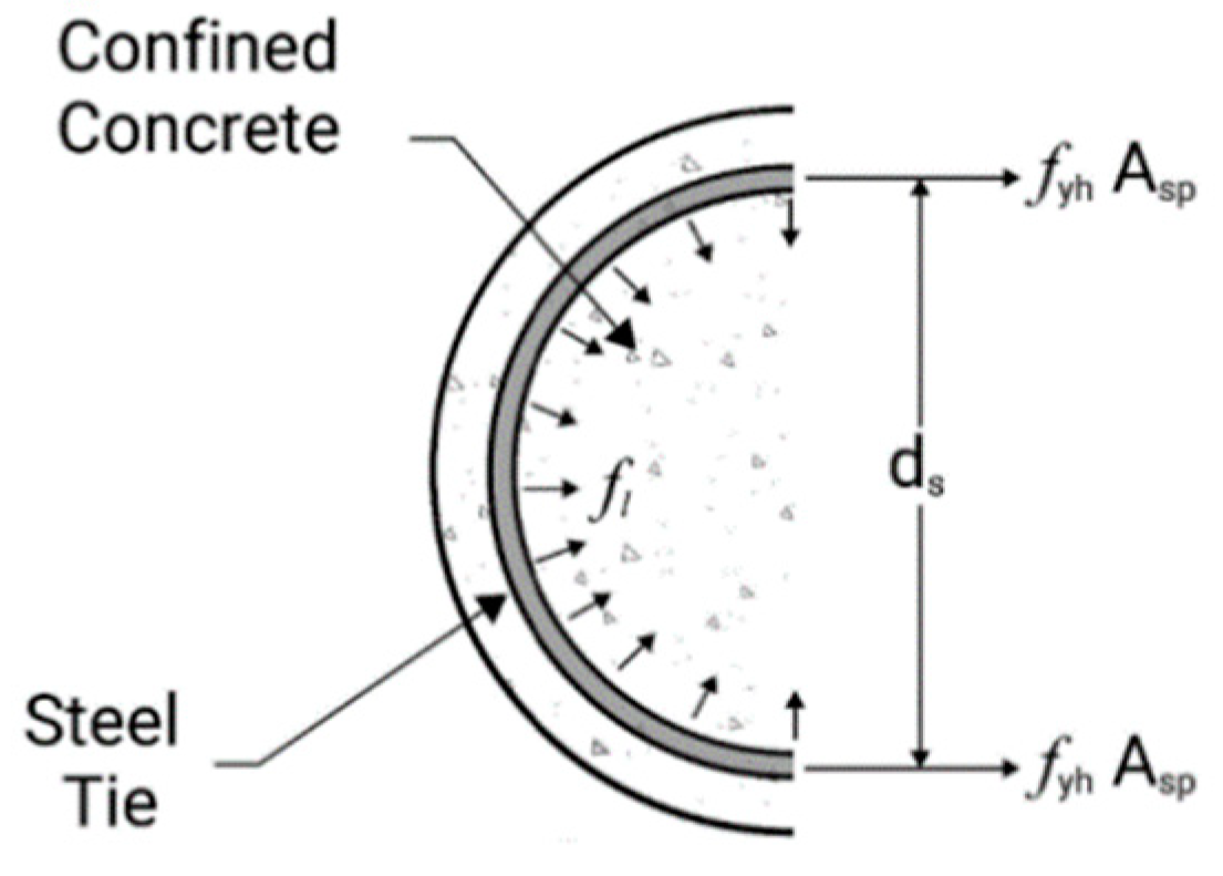
Figure 3.
Reprinted with permission from ref. [35]. Copyright 2020 U.S. Tire Manufacturers Association.
Figure 3.
Reprinted with permission from ref. [35]. Copyright 2020 U.S. Tire Manufacturers Association.

Figure 4.
Reprinted with permission from ref. [35]. Copyright 2020 U.S. Tire Manufacturers Association.
Figure 4.
Reprinted with permission from ref. [35]. Copyright 2020 U.S. Tire Manufacturers Association.
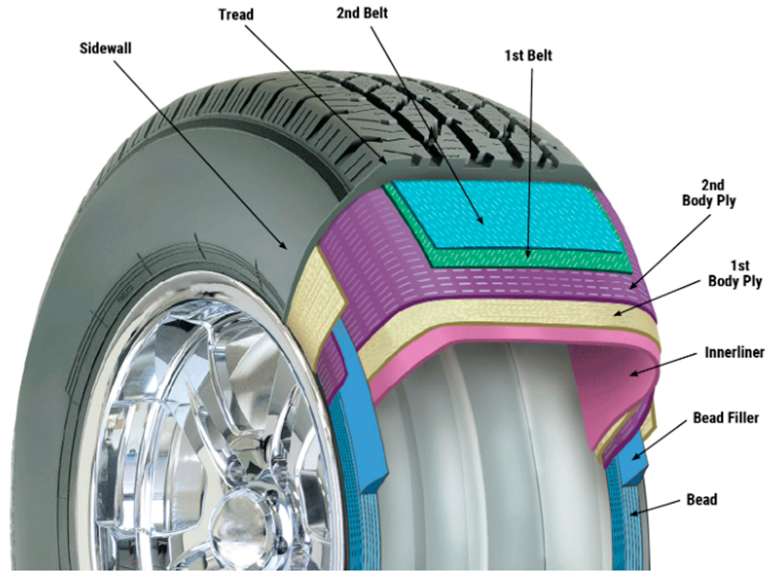
Figure 5.
Dimensions of Tires Used: (a) 225/75R16, (b) 235/80R16, (c) 215/85R16.
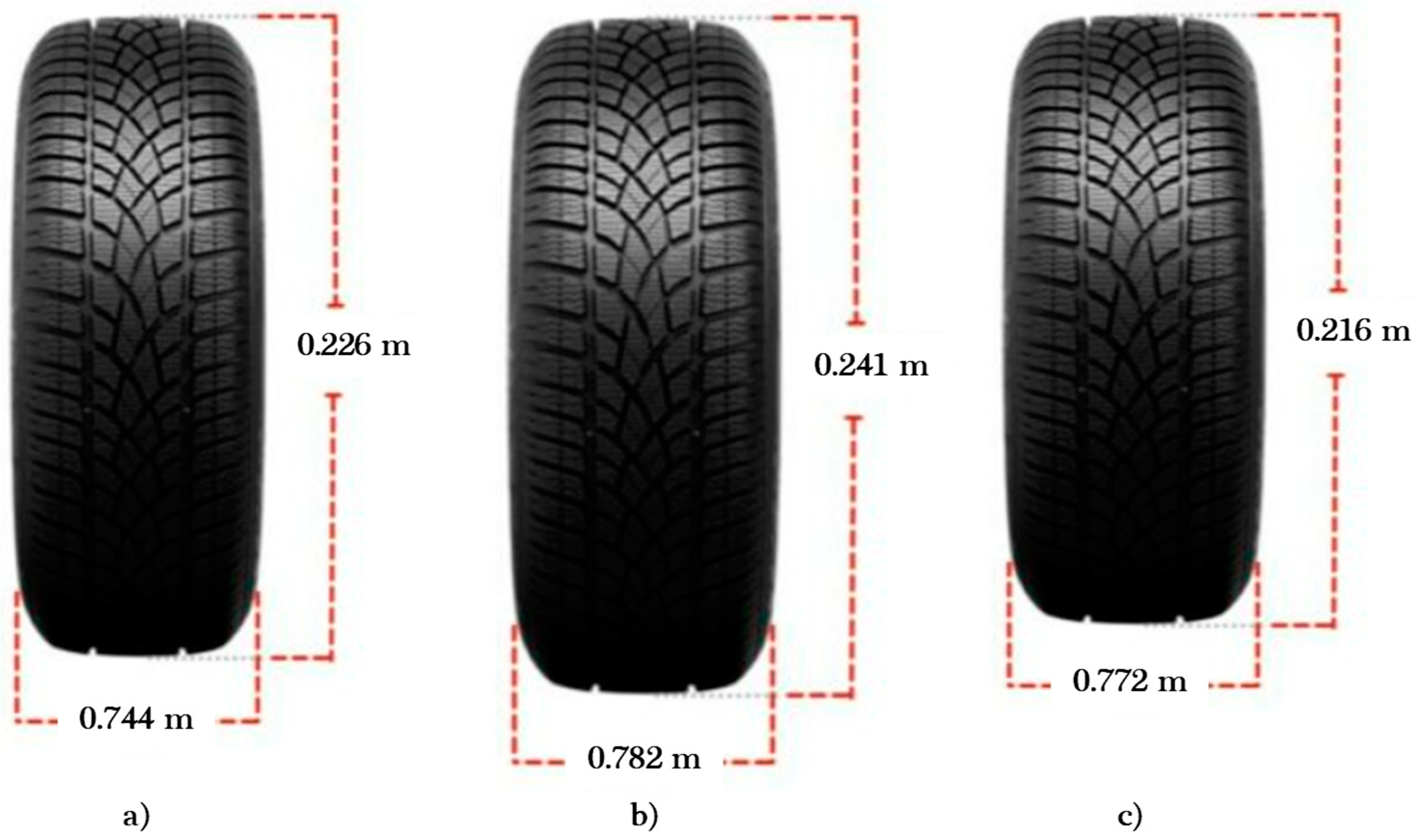
Figure 6.
Preparation of UC Specimen: (a) sonotube, (b) specimen after pour, (c) sonatube in formwork, (d) cured specimen.
Figure 6.
Preparation of UC Specimen: (a) sonotube, (b) specimen after pour, (c) sonatube in formwork, (d) cured specimen.
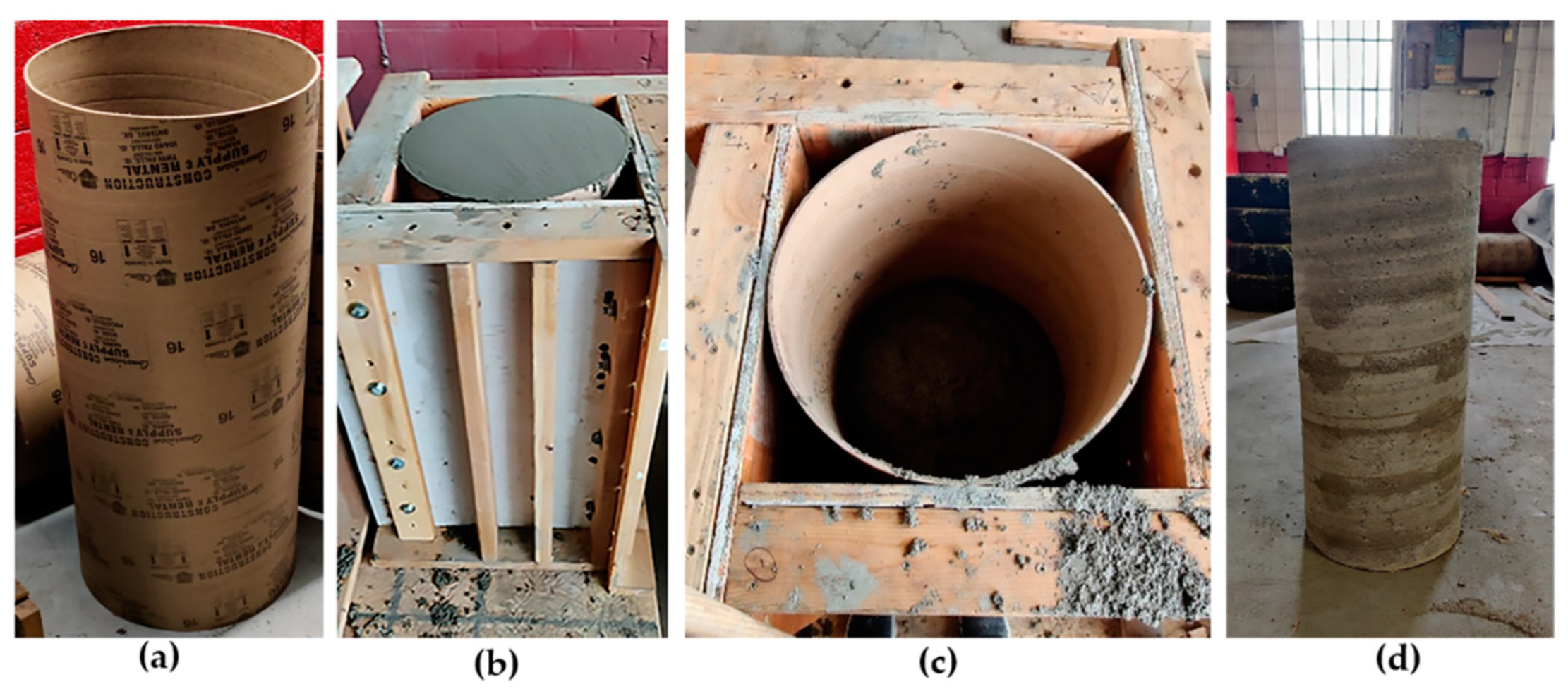
Figure 7.
Preparation of TC Specimen: (a) tires stacked side view, (b) tires top view, (c) tires in formwork for pour, (d) cured specimen.
Figure 7.
Preparation of TC Specimen: (a) tires stacked side view, (b) tires top view, (c) tires in formwork for pour, (d) cured specimen.

Figure 8.
Test setup for the compression testing of column specimens.
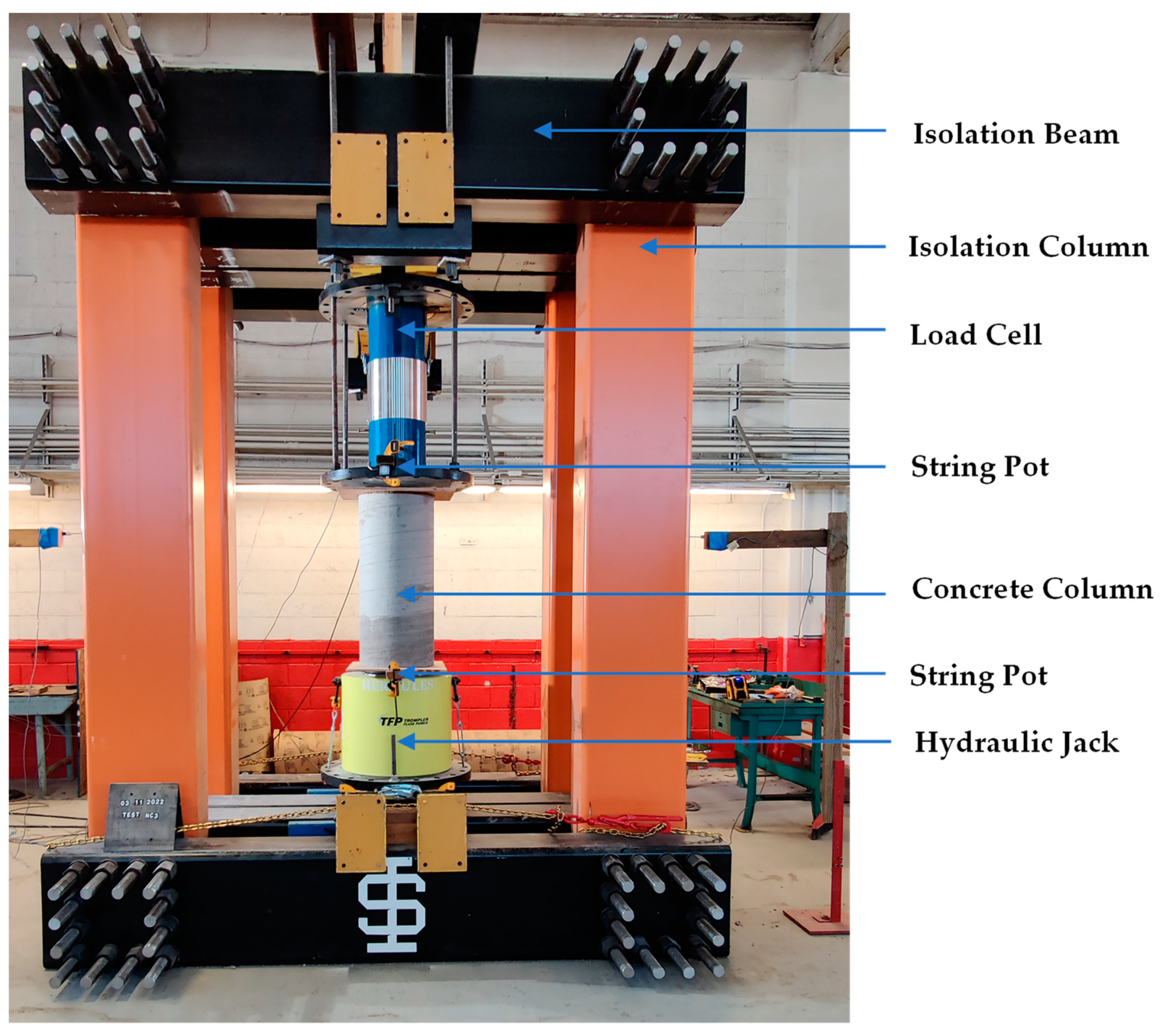
Figure 9.
Axial force and displacement relationship.

Figure 10.
The failure mode of UCNC specimen: (a) columnar failure, (b) conical failure.

Figure 11.
The failure mode (columnar failure) of UCRC specimen: (a) UCRC1, (b) UCRC2.
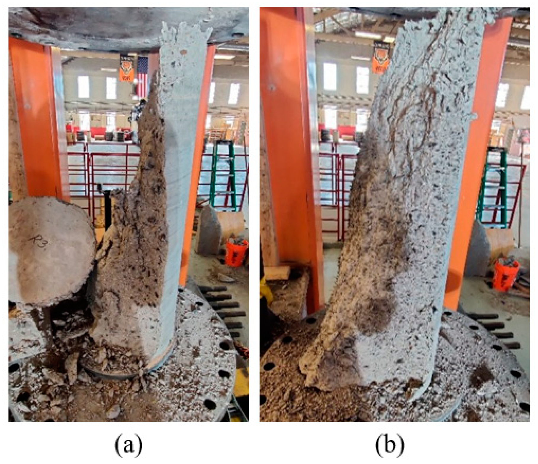
Figure 12.
Failure mode: (a) CCNC1 specimen, (b) close-up view of a split in tire-CCNC1, (c) CCNC2 specimen, (d) close-up view of a split in tire-CCNC2.
Figure 12.
Failure mode: (a) CCNC1 specimen, (b) close-up view of a split in tire-CCNC1, (c) CCNC2 specimen, (d) close-up view of a split in tire-CCNC2.

Figure 13.
Failure mode: (a) CCRC1 specimen, (b) close-up view of a split in tire-CCRC1, (c) CCRC2 specimen, (d) close-up view of a split in tire-CCRC2.
Figure 13.
Failure mode: (a) CCRC1 specimen, (b) close-up view of a split in tire-CCRC1, (c) CCRC2 specimen, (d) close-up view of a split in tire-CCRC2.

Figure 14.
Failure mode: (a) CCNCH1 specimen, (b) close-up view of a split in tire-CCNCH1, (c) CCNCH2 specimen, (d) close-up view of a split in tire-CCNCH2.
Figure 14.
Failure mode: (a) CCNCH1 specimen, (b) close-up view of a split in tire-CCNCH1, (c) CCNCH2 specimen, (d) close-up view of a split in tire-CCNCH2.

Figure 15.
Failure mode: (a) CCRCH1 specimen, (b) close-up view of a split in tire-CCRCH1, (c) CCRCH2 specimen, (d) close-up view of a split in tire-CCRCH2.
Figure 15.
Failure mode: (a) CCRCH1 specimen, (b) close-up view of a split in tire-CCRCH1, (c) CCRCH2 specimen, (d) close-up view of a split in tire-CCRCH2.

Figure 16.
Unconfined concrete columns comparison.
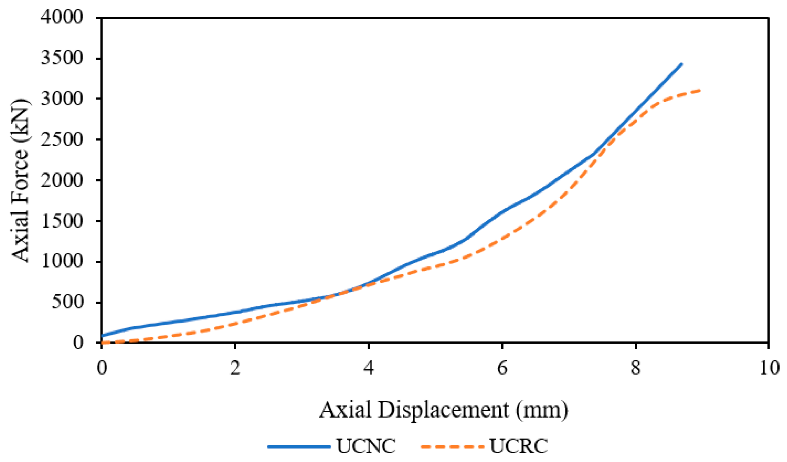
Figure 17.
Confined concrete columns comparison.
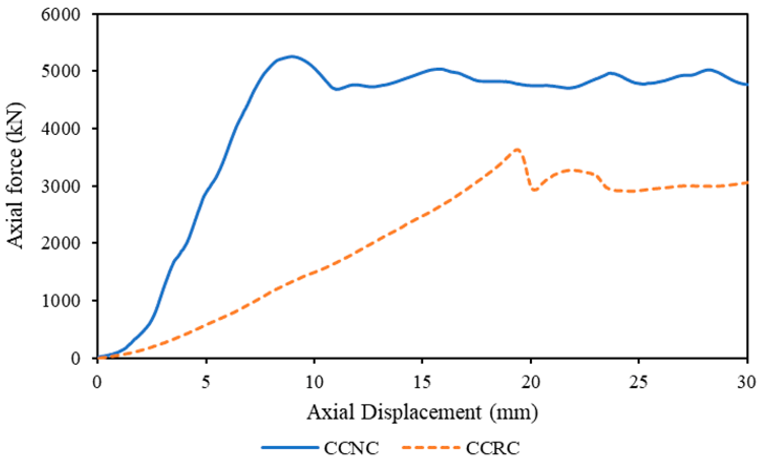
Figure 18.
Confined concrete columns with tires cut along the height comparison.
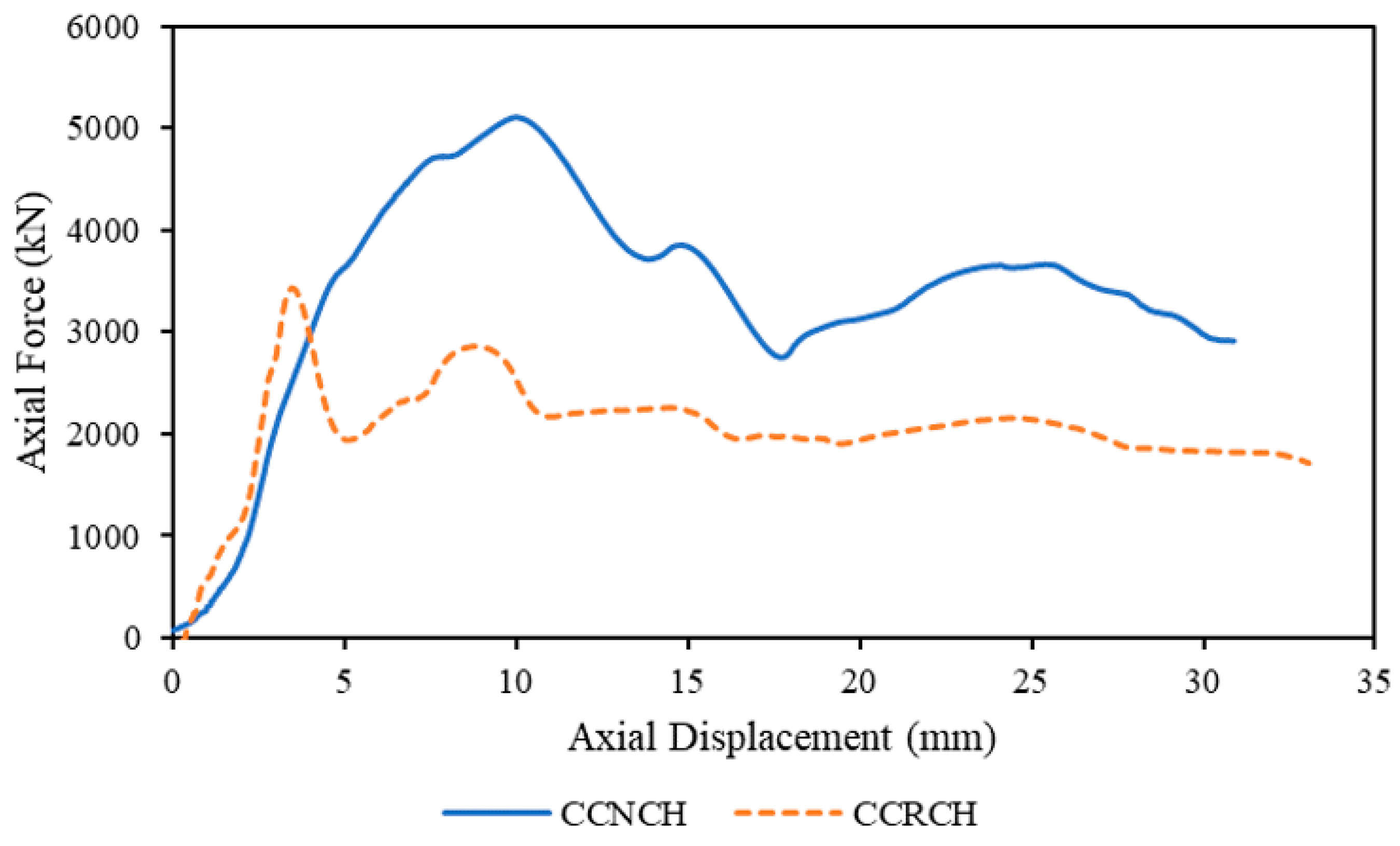
Figure 19.
Normal concrete columns comparison.
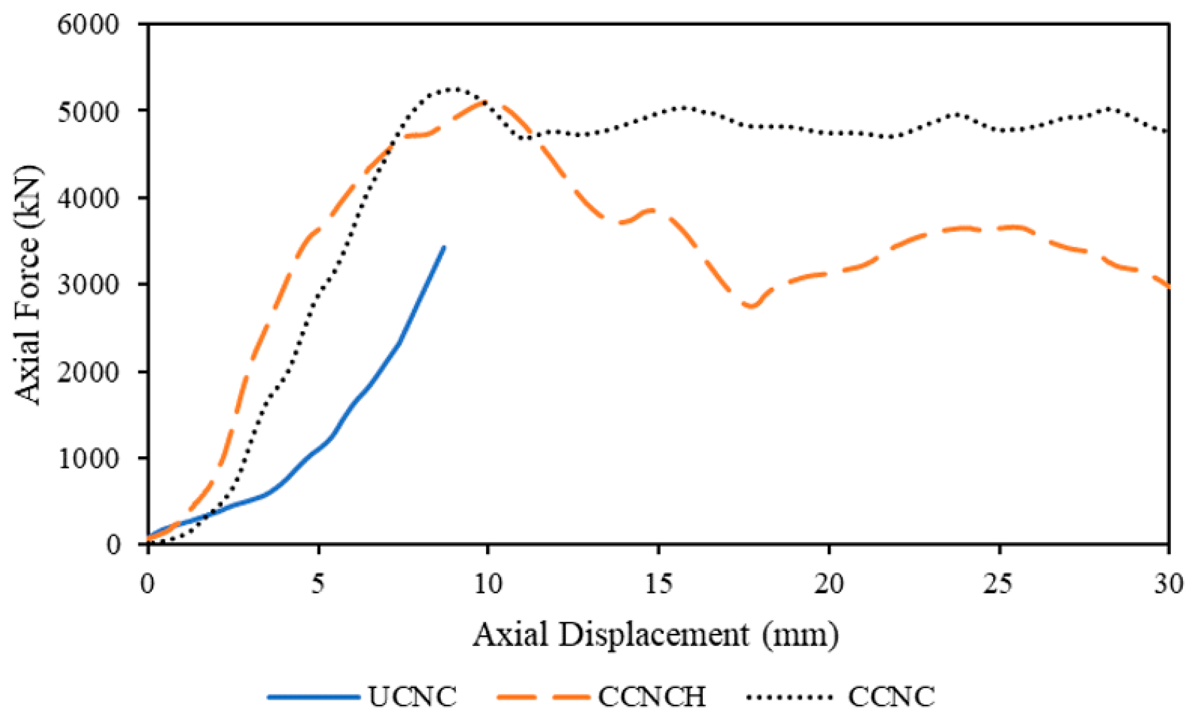
Figure 20.
Rubberized concrete columns comparison.
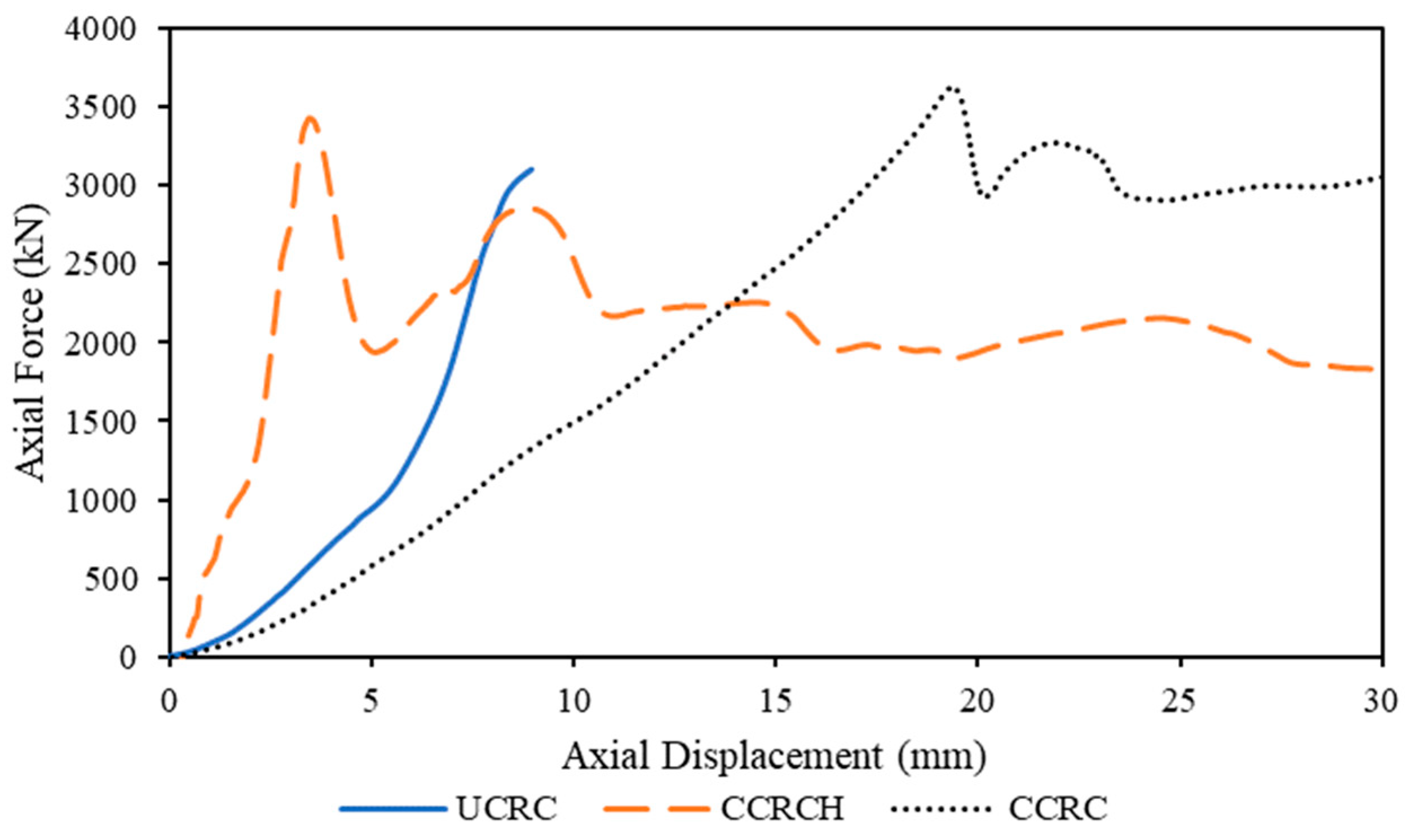
Figure 21.
Confinement by tire.


Table 1.
Mix Design for Normal Concrete and Rubberized Concrete.
| Normal Concrete | Rubberized Concrete | ||
|---|---|---|---|
| Material | Weight (kg/cu.m) | Material | Weight (kg/cu.m) |
| Cement | 352.4 | Cement | 520.6 |
| Fly Ash | 296.9 | Fly Ash | 130.4 |
| Fine Aggregate | 1210.9 | Fine Aggregate | 1210.9 |
| Coarse Aggregate | 576.7 | Coarse Aggregate | 490.2 |
| Water | 267.5 | Rubber Aggregate | 29.0 |
| Water | 267.5 | ||
Table 2.
Compressive strength of the sample cylinder.
| Specimen | Average Compressive Strength (MPa) |
|---|---|
| Unconfined Normal Concrete | 35.2 |
| Confined Normal Concrete | 34.8 |
| Confined Rubberized Concrete | 35.1 |
| Unconfined Rubberized Concrete | 34.9 |
Table 3.
Summary of performance factors for all specimens.
| Type: Unconfined | Maximum Axial Force (kN) | Corresponding Displacement (mm) | Maximum Stress (MPa) | Strain (mm/mm) | Energy Dissipation (kJ) |
|---|---|---|---|---|---|
| UCNC1 | 3426.9 | 5.99 | 26.4 | 0.00654 | 7.99 |
| UCNC2 | 2783.9 | 10.13 | 21.4 | 0.00811 | 9.15 |
| UCRC1 | 3258.5 | 9.96 | 25.1 | 0.01089 | 11.75 |
| UCRC2 | 2998.7 | 8.89 | 23.1 | 0.00965 | 10.53 |
| CCNC1 | 6031.7 | 10.1 | 46.5 | 0.01109 | 94.18 |
| CCNC2 | 5093.2 | 11.4 | 39.2 | 0.01259 | 46.77 |
| CCRC1 | 3567.0 | 9.1 | 27.5 | 0.00990 | 12.68 |
| CCRC2 | 4317.8 | 30.2 | 33.3 | 0.03323 | 62.10 |
| CCNCH1 | 4948.2 | 10.7 | 38.1 | 0.01177 | 47.03 |
| CCNCH2 | 5412.2 | 9.9 | 41.7 | 0.01095 | 55.29 |
| CCRCH1 | 4752.4 | 2.4 | 36.6 | 0.00259 | 9.59 |
| CCRCH2 | 3714.7 | 7.9 | 28.6 | 0.00870 | 23.75 |
Table 4.
Confinement effectiveness of confined column.
| Type | Average Maximum Compressive Stress (f′cc) MPa | Average Confinement Effectiveness, kl (f′cc/f′co) |
|---|---|---|
| CCNC | 42.8 | 1.78 |
| CCRC | 30.4 | 1.26 |
| CCNCH | 39.9 | 1.67 |
| CCRCH | 36.6 | 1.35 |
Table 5.
Confinement pressures of different tires.
| Tire | Inner Diameter (mm) | Threaded Section Width (mm) | Confining Pressure, fl (MPa) |
|---|---|---|---|
| 225/75R16 | 712.5 | 200.7 | 2.24 |
| 235/80R16 | 750.6 | 210.8 | 2.24 |
| 215/85R16 | 740.4 | 190.5 | 2.05 |
Table 6.
Actual confinement in columns.
| Type | Specimen | Actual Confinement (fl/f′co) |
|---|---|---|
| CCNC | CCNC1 | 0.094092 |
| CCNC2 | 0.094092 | |
| CCRC | CCRC1 | 0.093553 |
| CCRC2 | 0.093553 | |
| CCNCH | CCNCH1 | 0.094092 |
| CCNCH2 | 0.094092 | |
| CCRCH | CCRCH1 | 0.093553 |
| CCRCH2 | 0.093553 |
Disclaimer/Publisher’s Note: The statements, opinions and data contained in all publications are solely those of the individual author(s) and contributor(s) and not of MDPI and/or the editor(s). MDPI and/or the editor(s) disclaim responsibility for any injury to people or property resulting from any ideas, methods, instructions or products referred to in the content. |
© 2023 by the authors. Licensee MDPI, Basel, Switzerland. This article is an open access article distributed under the terms and conditions of the Creative Commons Attribution (CC BY) license (https://creativecommons.org/licenses/by/4.0/).
Share and Cite
MDPI and ACS Style
Mahat, M.; Acharya, M.; Acharya, M.; Mashal, M. Use of Waste Tires as Transverse Reinforcement and External Confinement in Concrete Columns Subjected to Axial Loads. Sustainability 2023, 15, 11620. https://doi.org/10.3390/su151511620
AMA Style
Mahat M, Acharya M, Acharya M, Mashal M. Use of Waste Tires as Transverse Reinforcement and External Confinement in Concrete Columns Subjected to Axial Loads. Sustainability. 2023; 15(15):11620. https://doi.org/10.3390/su151511620
Chicago/Turabian StyleMahat, Mahesh, Mahesh Acharya, Manish Acharya, and Mustafa Mashal. 2023. "Use of Waste Tires as Transverse Reinforcement and External Confinement in Concrete Columns Subjected to Axial Loads" Sustainability 15, no. 15: 11620. https://doi.org/10.3390/su151511620
Note that from the first issue of 2016, this journal uses article numbers instead of page numbers. See further details here.