Article

An Analysis of the Heat Transfer Characteristics of Medium-Shallow Borehole Ground Heat Exchangers with Various Working Fluids

1
School of Thermal Engineering, Shandong Jianzhu University, Jinan 250101, China
2
Shandong Geology and Mineral Resources Terrestrial Heat Development Investment Co., Ltd., Jinan 250013, China
*
Author to whom correspondence should be addressed.
Sustainability 2023, 15(16), 12657; https://doi.org/10.3390/su151612657
Submission received: 1 August 2023 / Revised: 11 August 2023 / Accepted: 17 August 2023 / Published: 21 August 2023

Abstract

:
Medium-shallow borehole ground heat exchangers (BGHEs) utilize a burial depth ranging from 200 to 600 m. The heat exchange capacity of a single medium-shallow BGHE is higher than that of a single shallow BGHE. Compared to medium-deep BGHEs, the cost of medium-shallow BGHEs is lower, and both heating and cooling can be achieved, while the former can only be used for heating. However, there is a relative lack of research on the heat transfer characteristics of medium-shallow BGHEs, especially on the influence of the working fluid type on the heat transfer performance of BGHEs. This study aimed to investigate the impact of different working fluids on the performance of medium-shallow BGHEs. First, a heat transfer model for medium-shallow BGHEs was established considering the ground temperature gradient and geothermal heat flow, and its accuracy was validated using experimental test data. Second, the model was used to compare and analyze the effects of various working fluids on the heat transfer performance, pressure loss, and potential environmental benefits of BGHEs. Based on economic analysis, CO2 was determined to be the most suitable working fluid among the organic fluids considered. Finally, the influence of the number of boreholes and the type of working fluid on the heat transfer performance of borehole clusters consisting of 2 and 4 boreholes was analyzed using the superposition principle. The results indicated that CO2 could provide the highest heat transfer among the various working fluids selected in this study, as its heat extraction and heat dissipation were approximately 15% and 12% higher than those achieved by water. Isobutane (R600a) achieved the highest net heat and emission reduction, surpassing water by 66.7% and 73.6%, respectively. Regarding the four boreholes, the outlet temperature of the BGHEs gradually decreased at the end of each heating season. After 10 years of operation, the value decreased by approximately 2 °C. The results in this paper provide a theoretical basis and technical guidance for the rational selection of working fluids and improvements in the heat transfer performance of BGHEs, which could promote the development and application of medium-shallow geothermal energy sources.

1. Introduction

The international community is facing energy shortages due to economic development and extreme weather [1], and the development of clean and renewable energy is important to ensure continuous energy supplies. The global demand for crude oil (including biofuels) in 2022 amounted to 99.57 million barrels per day, and this is projected to increase to 101.89 million barrels per day in 2023 [2]. However, due to the overexploitation of conventional oil and gas fields, these reserves are being gradually depleted; thus, the development of clean and renewable energy is important to ensure a sustainable supply of energy [3]. As a clean and renewable resource, geothermal energy has the characteristics of abundant reserves and wide distribution, and its development and utilization are important for achieving carbon neutrality [4]. The direct use of geothermal energy for heat production worldwide can save 26.2 million tons of equivalent oil resources and reduce atmospheric CO2 emissions by 252.6 million t. If the emission reduction of ground-source heat pump cooling is considered, this would be equivalent to an additional reduction of 1810 tons of fuel oil per year, as well as burning 15 million tons of carbon pollution from fuel oil [5,6]. Ground-source heat pumps are one of the most widely used forms of geothermal energy in the world, accounting for 59.2% of the total annual energy consumption and 71.6% of the total installed capacity. With the increasing emphasis on geothermal energy, the Global Geothermal Alliance (GGA) promises that, by 2030, the amount of geothermal heating will increase by at least three times compared to that in 2014 [7]. With the continuous development of theoretical research and exploration technology, geothermal resources will become an indispensable part of clean energy in the future international society.
The buried-pipe ground-source heat pump system is one of the most widely used systems in the development of geothermal resources. It consists of three parts: the main body of the heat pump room, the BGHEs, and the end of the indoor air conditioner. The heat transfer of BGHEs is a complex non-steady-state process [8]. Therefore, research on the heat transfer characteristics of BGHEs is the main difficulty in improving the performance of ground-source heat-pump air conditioning systems. In recent years, many scholars have conducted research on the heat transfer characteristics of shallow BGHEs and medium-deep BGHEs, and have achieved important guiding conclusions. Regarding the heat transfer analysis of vertical borehole heat exchangers, the line heat resource model [9], the infinite-length linear heat source theory [10], the finite-length linear heat source model [11], and the infinite cylindrical heat source model are mostly used [12] as the basis. Regarding two-dimensional models, Diao and Zeng. [13,14] considered the change in fluid temperature in the depth direction and the axial convective heat transfer, and proposed a single U-shaped tube and double U-shaped tube borehole heat transfer analysis quasi-3D model. Based on the sensitivity study, Saeed et al. [15] found that fracture aperture, rock matrix permeability, and wellbore radius are three critical parameters to improve the operation efficiency of the enhanced geothermal system. A. Amiri et al. [16] investigated the heat transfer enhancement in liquid coolers by applying ultrasonic vibrations. Lyu et al. [17] used a three-dimensional steady-state model to analyze the entire temperature field of a single U-shaped tube heat exchanger in a shallow borehole and found that the length of the U-shaped tube is the main factor affecting the efficiency and cost of geothermal development. Based on these pioneering studies, many heat transfer models of shallow and medium-deep BGHEs have been proposed by scholars. Note that the heat transfer models in the above articles did not consider the utilization of medium-shallow geothermal energy sources. The lower number of wells drilled in medium-shallow layers compared to shallow layers provides the advantage of occupying a small area; compared with BGHEs in medium-deep layers, this has the characteristics of shallower depth and lower investment, and it is easier to exchange heat with the soil, which can achieve heating in winter and cooling in summer. At present, there are engineering practices related to medium-shallow BGHEs in Northeast China, but there are relatively few studies on the heat transfer model and heat transfer characteristics of medium-shallow BGHEs.
With the application and development of ground-source heat pump systems, medium-deep casing borehole ground-source heat pump systems, including several or more than a dozen borehole groups, are gradually being applied to large buildings [18]. Deng et al. [19] conducted a short-term field measurement study on a medium-deep ground-source heat pump project with five boreholes. The test results showed that the heat transfer efficiency per unit length of BGHE in the project ranged between 61 and 144 W/m. In addition to experimental research, Welsch et al. [20] used FEFLOW v 6.2 software to study the heat transfer characteristics of a thermal energy storage system (TES) consisting of 7 to 37 medium-deep boreholes. Cai et al. [21] used OpenGeoSys-5 software to construct a numerical model for deep BGHEs with five boreholes, and completed a running simulation for a heating season using a high-performance workstation, which took 143 h. Yu et al. [22] used a dimensionality reduction model to establish a segmented two-dimensional numerical model of a deep borehole U-shaped tube in cylindrical coordinates. Regarding medium-deep BGHEs, the spatial scale needs to cover a span from millimeters to thousands of meters, and the time scale needs to complete the span of the whole life cycle from hours to decades. Therefore, if a numerical method is used to establish a 3D model, the number of grids leads to a large amount of computation, and the hardware requirements of the computer are higher.
Factors such as the buried pipe method, buried pipe depth, soil properties, and surface meteorological parameters of the BGHEs all affect the heat transfer process of the heat exchanger, and the thermophysical parameters of the working fluid have a significant impact on the heat transfer efficiency [23]. Currently, water is the most common working fluid used for BGHEs. In engineering applications, problems with regard to the use of water often occur. For example, water can corrode wellbore materials, and the power of water pumps needs to be increased to overcome the flow resistance of working fluids. In recent years, with the use of organic working fluids in reservoir stimulation, drilling technology, and ground organic Rankine cycle (ORC) systems, relevant scholars have been exploring different types of working fluids in BGHEs. Saeed et al. [24] assessed the geothermal energy extraction potential from a discretely fractured reservoir using CO2. Mrityunjay et al. [25] combined the hydro-thermal reservoir scale numerical simulation with the analytical wellbore response model for the Soultz-sous-Forêts. The results indicate that, compared to water, CO2 shows lower temperature reduction in the faulted and the leakage zone for 50 years of operation. Wang [26] and Pumaneratkul et al. [27] proposed the use of ammonia and CO2 as the working fluids in BGHEs. Yildirim et al. [28] compared and analyzed the performance of different circulating fluid in coaxial heat exchangers and finally selected the optimal circulating fluid. Shi et al. [29] used a T2Well simulator to establish a borehole–reservoir coupling model and compared the heat extraction performance of the circulating fluid in medium-deep coaxial casing BGHEs with water and CO2 through a numerical model. Their results showed that CO2 is more advantageous regarding heat extraction performance, and potential environmental benefits can be achieved when CO2 is selected as the working fluid in medium-deep BGHEs. There are many studies on the influence of the thermophysical parameters of working fluids on the heat extraction capacity of BGHEs, but there are relatively few studies on the factors that impact the heat dissipation capacity and potential environmental benefits.
In summary, previous numerical simulations and experimental tests have made great contributions to the heat transfer analysis, optimization, and application of BGHEs. However, at present, the development and utilization of geothermal energy are mainly concentrated on shallow geothermal energy and medium-deep geothermal energy, and there are relatively few studies on medium-shallow geothermal energy. Moreover, existing research has rarely examined the type of working fluid for BGHEs [30]. Considering the above factors, a heat transfer model of medium-shallow BGHEs is established in this article based on the finite difference method. The model accounts for the heat transfer between the BGHE and soil, incorporating the axial geothermal gradient, and uses the Thomas algorithm to solve finite difference algebraic equations. Compared to conventional numerical models, this approach significantly increases calculation speed. Moreover, the model accounts for two modes—heat extraction in winter and heat dissipation in summer—and analyzes the heat transfer performance, potential environmental benefits, and economy of eight different types of working fluids. Finally, based on the numerical heat transfer model of a single BGHE in medium-shallow layers, the superposition principle is applied to study the variation law of the inlet and outlet temperature of the medium-shallow layer borehole tube group. In this model, the solution of the three-dimensional heat transfer problem outside the borehole of middle-shallow BGHEs is decomposed into the superposition of the solution of the two-dimensional temperature response of each single borehole. Thus, the dimensionality reduction calculation of complex three-dimensional problems can be completed, which significantly reduces the heat transfer calculation workload of the heat exchanger in medium-shallow BGHEs. This work provides a theoretical basis for the optimal design and reasonable selection of working fluids for medium-shallow BGHEs.

2. Heat Transfer Model

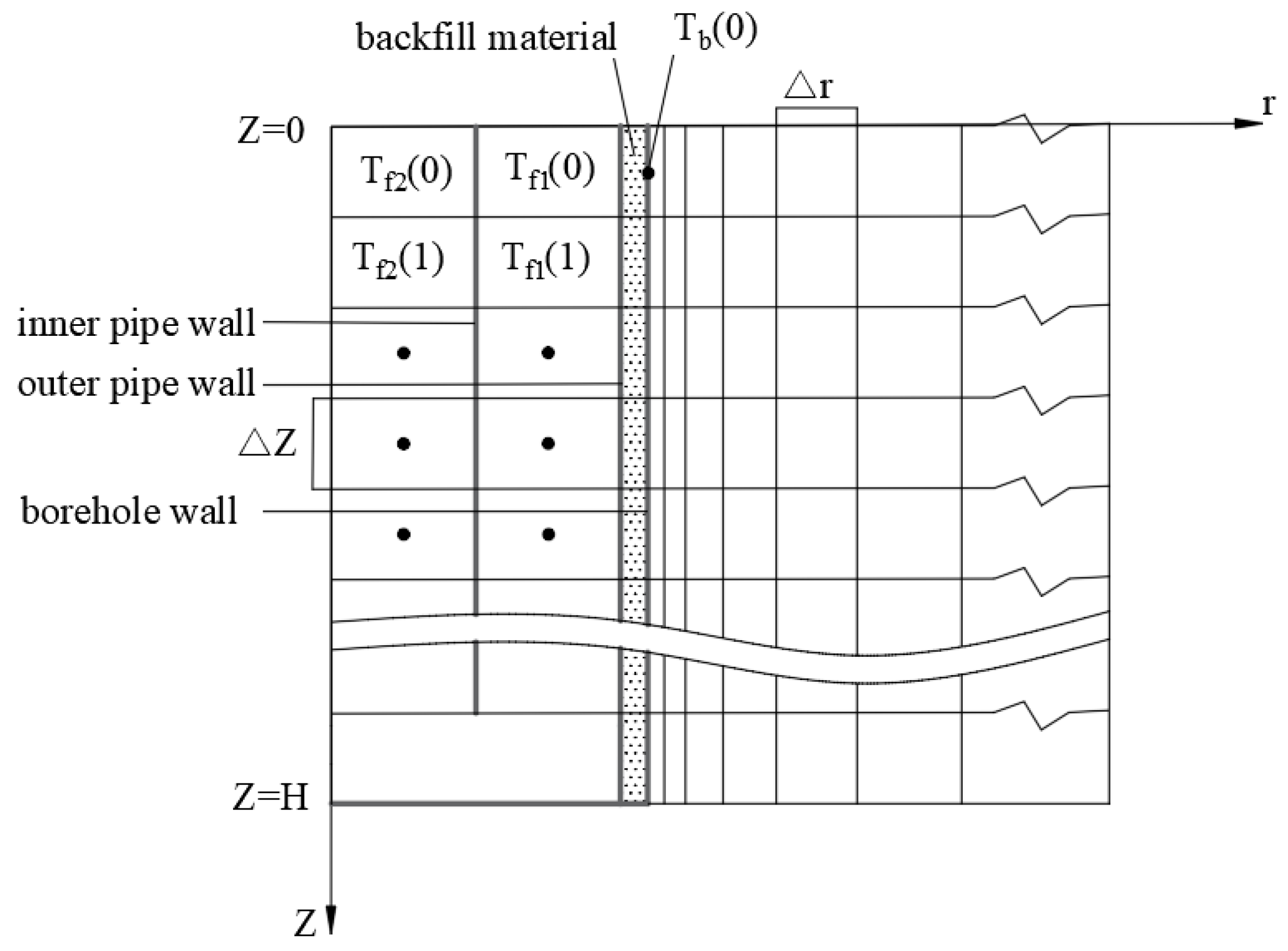
2.1. Description of the Borehole Heat Transfer Problem

Medium-shallow BGHEs are usually located 200~600 m underground, and their structure mostly adopts a coaxial sleeve type. When cooling underground, the flow form of “inner pipe in and outer pipe out” is adopted; heat is taken from the ground when the flow form of “outer pipe in and inner pipe out” is adopted; and when the flow form of the working fluid is “outer pipe in and inner pipe out”, the schematic diagram of its structure is shown in Figure 1. The outer tube of the heat exchanger is made of a steel pipe, and the inner tube is made of a material with low thermal conductivity, such as polyethylene or polypropylene. A backfill material is injected into the gap between the heat exchanger and the borehole to ensure that the heat exchanger is in close contact with the borehole wall while improving the heat transfer performance.
In winter, the borehole ground-source heat pump system transfers the heat in the soil to the room through the heat exchanger buried in the ground and simultaneously stores the cold energy for summer use; in summer, the working fluid passes through high-strength polyethylene pipes circulating in a closed loop; the heat is transferred to the ground, and at the same time it is stored for winter use. The soil provides a good source of energy storage, which enables the seasonal transfer of energy. Studies have confirmed that medium-shallow BGHEs have excellent unbalanced load carrying capacities and are suitable for long-term use in areas with unbalanced building cooling and heating loads [31].
In the process of establishing numerical models for traditional BGHEs, the “quasi-three-dimensional” model is commonly used to describe the heat transfer inside the borehole. This model considers not only the two-dimensional heat conduction in the cross-sectional area, but also the convective heat transfer in the axial direction and the variation of fluid temperature in the depth direction. However, a traditional BGHE numerical model often relies on the characteristics of a borehole heat exchanger with an extremely long structure, ignoring the heat conduction along the axial direction in the borehole and the heat capacity of materials such as backfill, pipes, and working fluid. Based on the “quasi-three-dimensional” model of heat transfer in the boreholes mentioned above, in order to simulate the heat transfer more accurately inside the borehole, this paper proposes a “modified quasi-three-dimensional model” which takes into account the effect of fluid temperature over time and material heat capacity. To simplify the model and facilitate the solution, the following basic assumptions are adopted [32]:
(1)
The radial boundary is sufficiently far, and it can be regarded as an adiabatic boundary.
(2)
The soil around the BGHE is regarded as one or several horizontal formations of uniform medium, each layer is a uniform medium, and its thermal properties do not change with temperature.
(3)
The working fluid maintains a turbulent flow state in the borehole, and the physical properties of the working fluid do not change with temperature.
(4)
The terrestrial heat flow qg, W/m2, is considered to be evenly distributed in the underground soil area.
(5)
In the initial time domain, there is no disturbance everywhere, and the steady-state temperature distribution and uniform initial ground temperature are maintained.

2.2. Flow Heat Transfer Model of the Working Fluid

Different flow forms of the working fluid in BGHEs will lead to differences in the temperature distribution and heat transfer. According to energy conservation, when the working fluid enters from the annular tube and returns from the inner tube, the governing equation is expressed as:
C 1 T f 1 z , τ τ = T f 2 z , τ T f 1 z , τ R 2 + T b z , τ T f 1 z , τ R 1 + M c T f 1 z , τ z C 2 T f 2 z , τ τ = T f 1 z , τ T f 2 z , τ R 2 M c T f 2 z , τ z   0     z H
When the working fluid enters from the inner tube and returns from the annular tube, the governing equation of the working fluid temperature is:
C 1 T f 1 z , τ τ = T f 2 z , τ T f 1 z , τ R 2 + T b z , τ T f 1 z , τ R 1 M c T f 1 z , τ z C 2 T f 2 z , τ τ = T f 1 z , τ T f 2 z , τ R 2 + M c T f 2 z , τ z   0     z H
In this equation, Tf1 and Tf2 are the fluid temperature in the outer tube and inner tube, respectively, °C; c is the specific heat capacity of the fluid, J/(kg‧K); M is the mass flow rate of the fluid in the tube, kg/s; C1 and C2 are the heat capacities of the outer tube and inner tube per unit length, respectively, J/(m3‧K); R1 and R2 are the thermal resistance between the fluid in the outer tube and the borehole wall, and the thermal resistance between the fluid in the inner tube and the outer tube, respectively, m‧K/W; z is the vertical space node; and τ is time, s.
R 1 = 1 π d 1 i h 1 i + 1 2 π λ 1 ln d 1 o d 1 i + 1 2 π λ b ln d b o d 1 o   R 2 = 1 π d 2 i h 2 i + 1 2 π λ 2 ln d 2 o d 2 i + 1 π d 2 o h 2 o
λ1, λ2, and λb are the thermal conductivity coefficients of the outer pipe, inner pipe, and backfill material, respectively, W/(m·K); d1o and d1i are the outer diameter and inner diameter of the outer pipe, respectively, m; d2o and d2i are the outer diameter and inner diameter of the inner pipe, respectively, m; dbo is the borehole diameter, m; h1i is the heat transfer coefficient between the fluid and the inner wall of the outer pipe, W/(m2·K); h2i is the heat transfer coefficient between the fluid and the inner wall of the inner pipe, W/(m2·K); and h20 is the heat transfer coefficient between the fluid and the outer wall of the inner tube, W/(m2·K).
C 1 = π 4 C w d 1 i 2 d 2 o 2 + C 1 d 1 o 2 d 1 i 2 + C b d b o 2 d 1 o 2   C 2 = π 4 C w d 2 i 2 + C 2 d 2 o 2 d 2 i 2
Cw is the volume heat capacity of water, J/(m3·K), and Cb is the volume heat capacity of the backfill material, J/(m3·K).
The definite solution condition of the differential equations is that the outer tube and the inner tube are connected at the bottom of the borehole; in other words, the temperature is the same.
T f 1 = T f 2 , z = H
According to the determined heat transfer, the boundary condition at the top of the borehole is defined. When the working fluid adopts “outer tube inlet and inner tube outlet” and “inner tube inlet and outer tube outlet”, the boundary conditions are shown in Equation (6) and Equation (7), respectively:
T f 1 = T f 2 Q M c , z = 0
T f 1 = T f 2 + Q M c , z = 0
where H is the drilling depth, m, and Q is the heat transfer, W.
The basic difference schemes for the differential processing of unsteady heat conduction equations are forward difference and backward difference, and a solution method called the “chasing method” is adopted. The radial space step Δr of this numerical simulation adopts the form of variable step size, and the magnification factor is 1.2; in the longitudinal direction, due to the small temperature gradient, a larger longitudinal space step Δz can be used, which is 10 m, and the time step Δτ is 3600 s. To ensure the stability of the solution, after the space step is selected, the time step cannot be changed arbitrarily. The node equations of the temperature of the working fluid in a single borehole and multiple BGHEs are given below, and the grid division forms are shown in Figure 2 and Figure 3. Regarding a single BGHE, when the working fluid enters and exits from the annular tube and returns from the inner tube, the distribution expressions of its inlet and outlet temperatures are:
T f 1 0 = 1 B 1 B 3 T 0 f 1 0 + B 1 T b 0 + B 3 T 0 f 2 0 4 B 4 Q B 1 + 4 B 4 T f 2 0 / 1 + 4 B 4   T f 2 0 = B 2 T f 1 0 + B 5 T 0 f 2 1 + 1 B 5 T 0 f 2 0 / 1 + B 2
When the circulation form is that the inner pipe enters and the annular pipe returns, the distribution expressions of the inlet and outlet temperatures of the working fluid are:
T f 1 0 = 1 B 4 T 0 f 1 0 + B 4 T 0 f 1 1 + B 1 T b 0 + B 3 T f 2 0 / 1 + B 1 + B 3   T f 2 0 = B 2 + B 5 T f 1 0 + T 0 f 2 0 B 5 Q B 2 / 1 + B 2 + B 5
B 1 = Δ τ R 1 C 1 , B 2 = Δ τ R 2 C 2 , B 3 = Δ τ R 2 C 1 , B 4 = C w Δ τ C 1 Δ z , B 5 = C w Δ τ C 2 Δ z , Q B 1 = Q Δ τ C 1 Δ z , Q B 2 = Q Δ τ C 2 Δ z
where T0f1 and T0f2 are the fluid temperatures of the outer tube and the inner tube at the previous moment, respectively, °C; 0 and 1 are the longitudinal nodes; Δτ is the time step, s; Δz is the longitudinal space step, m; Cw is the volumetric heat capacity of water, J/(m3·K); C1 and C2 are the volumetric heat capacities of the outer tube and the inner tube, respectively, J/(m3·K); and Q is the heat transfer, W.
In this study, the numerical simulation program of the medium-shallow BGHEs was compiled by using Fortran and the temperature distribution can be determined at any time.

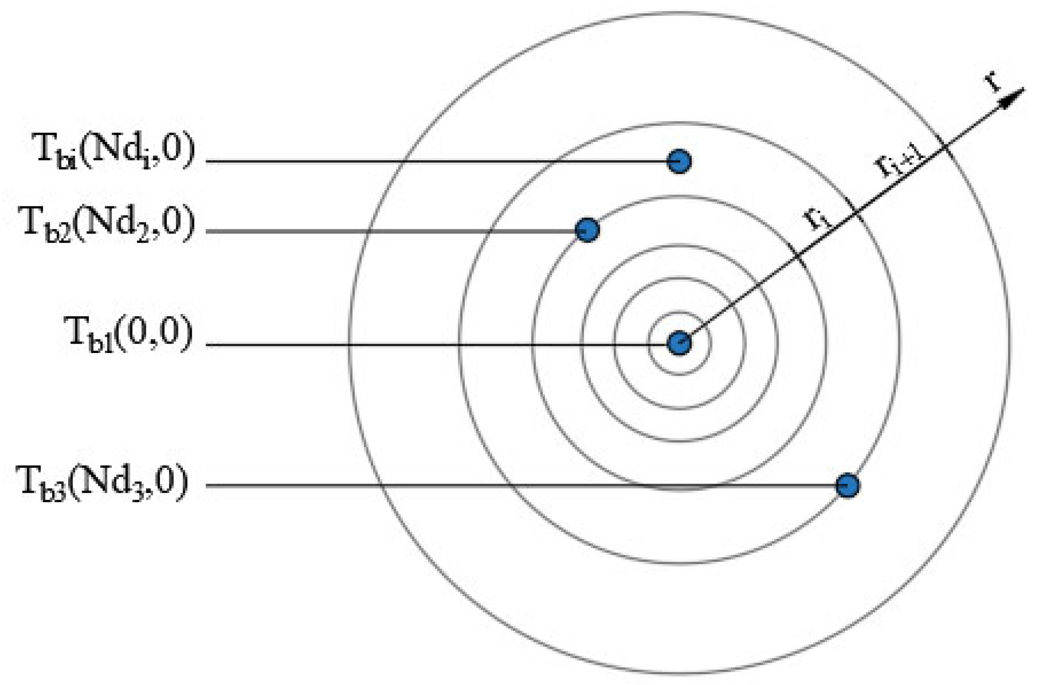
2.3. Introduction of the Dimension Reduction Algorithm for Multiple BGHEs
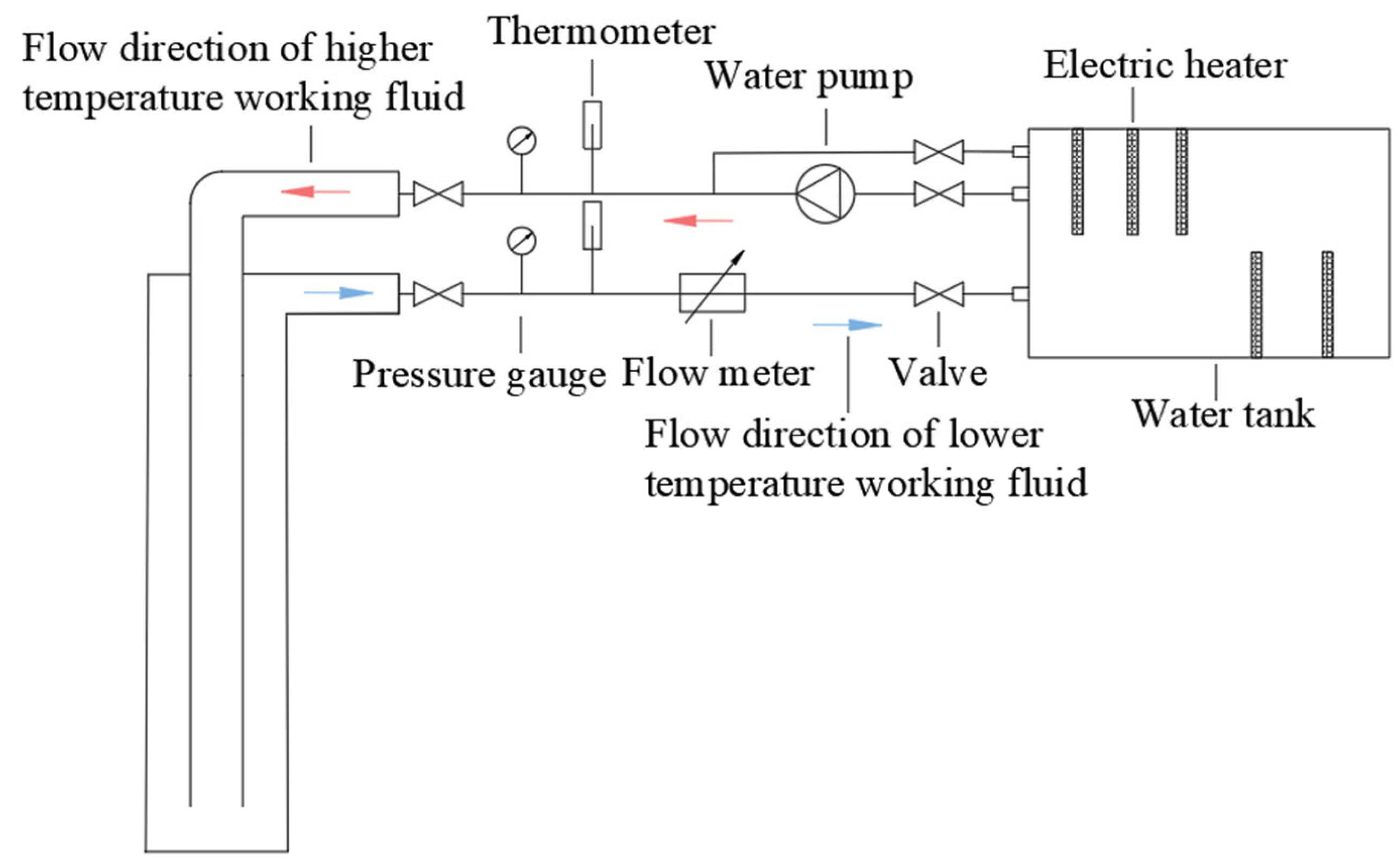
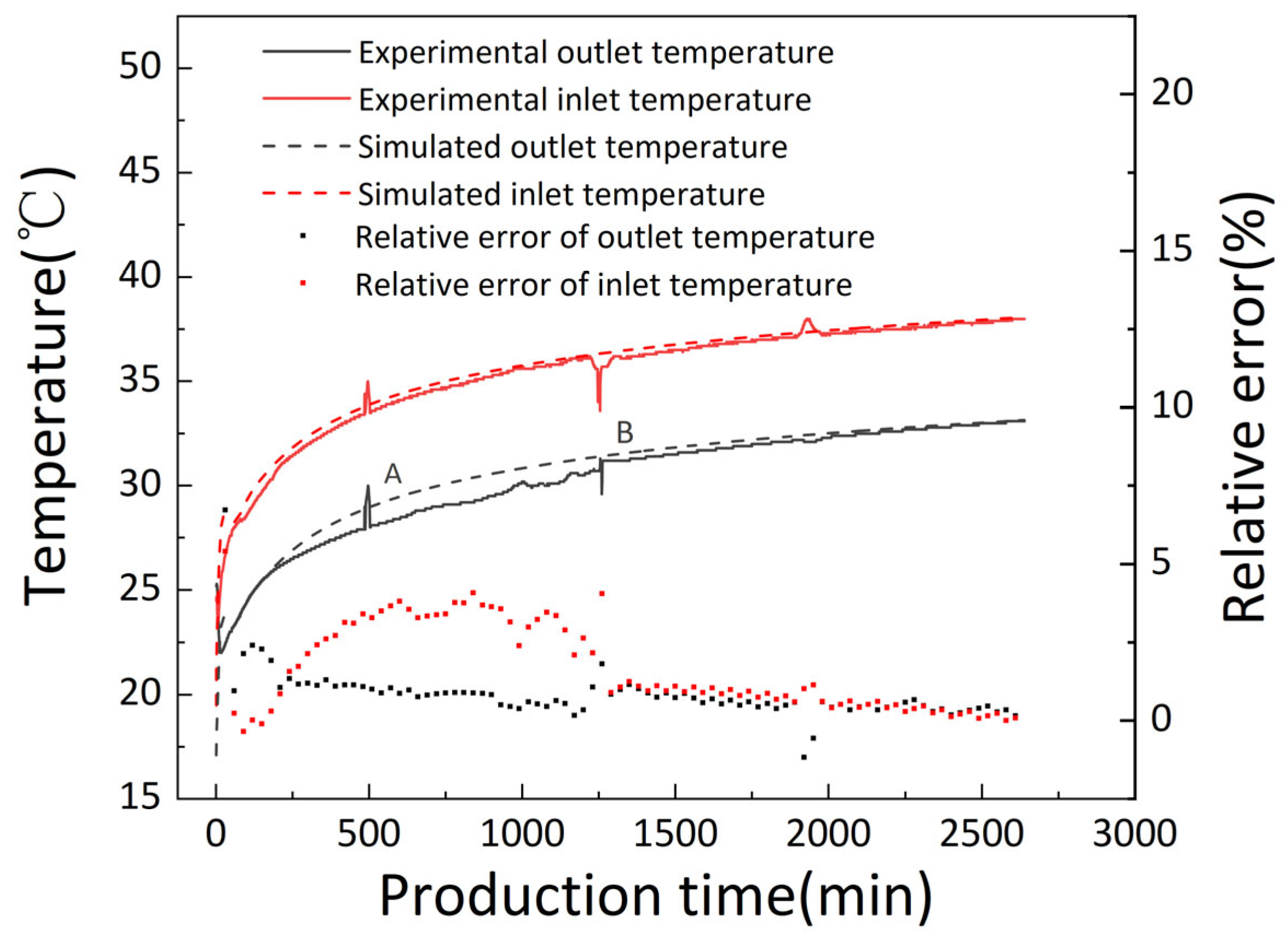
In practical engineering, the distance between boreholes of multiple BGHEs is much larger than the borehole radius. Therefore, the heat transfer problem of multiple BGHEs can satisfy the superposition principle, as shown in Equation (11). Regarding the heat transfer analysis of BGHEs with multiple boreholes, the superposition principle is used to decompose the heat conduction problem of the borehole group into the superposition of heat conduction problems of several single BGHEs, and the three-dimensional heat transfer problem is transformed into two-dimensional problems to achieve dimensionality reduction calculations [33]. Regarding the heat transfer calculation inside the borehole of a ground heat exchanger, the temperature of the borehole wall is the main focus. According to Equations (8) and (9), the inlet and outlet temperatures of the working fluid inside the borehole can be obtained from the borehole wall temperature Tb. According to the superposition principle, the borehole wall temperatures of multiple BGHEs can be considered as the superposition of multiple borehole wall temperatures, as shown in Equation (12).
r i j = x j x i 2 + y j y i 2 r b , j , i = 1 , 2 , , n ; j = 1 , 2 , , n ; i j
rij is the distance between any two boreholes, m; x and y are the horizontal coordinates; and rb,j is the radius of the jth borehole, m.
T b 0 = T b 1 0 , 0 + i = 2 n T b i N d i , 0
Tbi is the wall temperature of other boreholes, °C, and Ndi is the longitudinal node position of other boreholes. If it is not a node, the temperature can be calculated using the linear interpolation method.
By solving several two-dimensional problems of single-borehole heat exchangers, the three-dimensional heat transfer problem of multiple medium-shallow BGHEs can be solved.

3. Model Validation

To verify the accuracy of the model, an in situ geothermal development experiment was conducted in this study, and the simulation results were compared with the experimental test results. Table 1 lists the design parameters for the experimental tests. The experimental project is in Handan City, China. The buried pipe depth of this project is 300 m, and the working fluid flow rate is 3.5 m3/h. According to the experimental data measured under summer working conditions, the flow form of the working fluid is that the inner pipe enters and the annular pipe returns, the earth heat flow is set to 0.065 W/m2, and the average temperature in summer is 25 °C. The remaining simulation parameters are set the same as the experimental parameters. The specific operation process is shown in Figure 4. The initial temperature of the working fluid is considered the same as the rock soil temperature. The data measured through the experiment that runs continuously for 40 h help to verify the accuracy of the model. The comparison is shown in Figure 5.
Figure 5 shows that within 40 h of operation, there is a certain difference between the temperature of the inlet and outlet of the buried pipe tested through the experiment and the simulation results, but the overall trend is the same. During the operation, there were two periods of experimental data, including part A (480 to 520 min) and part B (1252 to 1290 min) that showed oscillations, and there were certain points with relative errors exceeding 5%. The relative error was calculated as described in Appendix A. The reason is that the experimental test was greatly affected by fluctuations in environmental temperature during the process of experimental data collection. When the temperature is too high or too low in comparison to the average summer air temperature, this can cause significant fluctuations in the experimental data. Furthermore, in the process of using this numerical model to simulate calculations, the influence of the above extreme air temperatures was ignored, and the average summer temperature was used as the air temperature parameter. Thus, it is possible that there are some points in Figure 5 with errors higher than 5%. Except for the two time intervals mentioned above, the relative error between the simulation and experimental test results remains within 5% during the operation time, indicating that the prediction model proposed in this paper is reliable for solving the underground heat transfer problem of medium-shallow BGHEs and is suitable for engineering applications.

4. Analysis and Comparison of the Working Fluid

4.1. Heat Transfer Performance of BGHEs

To analyze the effect of the working fluid type on the heat transfer performance of the BGHEs, the organic working fluid used in the ORC system is referenced in this study, and considering safety and environmental protection, eight kinds of working fluids are selected. Using Reference Fluid Thermodynamic and Transport Properties v 10.0 software, thermal parameters such as the density, viscosity, thermal conductivity, and volumetric heat capacity of the working fluid at various temperatures and pressures were acquired. Each fluid has a specific critical temperature and critical pressure, as shown in Table 2. In this study, the working fluid remains liquid in the buried tube heat exchanger, and the pressure at each point in the BGHEs is higher than the critical pressure of the working fluid.
The atmospheric temperature in winter and summer conditions is set to 12 °C and 25 °C, respectively, and the volume flow rate is set to 10 m3/h. Other buried pipe parameters and geological parameters are subject to experimental tests. To compare the heat transfer capacity of BGHEs under different types of working fluids, the heat transfer capacity indexes of BGHEs in winter and summer are defined in this paper. The heat transfer index is a virtual quantitative indicator determined through simulation, which facilitates communication between engineers and non-professionals. It is proposed that the heat exchanger is operated continuously for 4 months, which is defined as heat exchange with the inlet temperature not lower than 5 ℃ in winter and not higher than 31 ℃ in summer. Regarding the amount of heat exchange, the inlet temperature is not lower than 5 °C in winter, and the inlet temperature is not higher than 31 °C in summer. Due to the low flow rate of the working fluid in the BGHEs, there is enough time for heat transfer between the inner tube and the outer tube so that the outlet temperature of the fluid is higher than the ideal outlet temperature in the heat dissipation mode. In the heat extraction mode, the outlet temperature is lower than ideal, so the actual heat transfer capacity of the BGHEs is reduced. This phenomenon is called the thermal short circuit phenomenon or heat loss of the buried pipe. To compare the effects of different working fluids on the thermal short circuit phenomenon, the heat loss rate between the inner tube and the outer tube working fluid is expressed as follows:
α h = T b o t t o m T o u t T b o t t o m T i n
where αh is the heat loss rate, %; Tbottom is the bottom temperature of the BGHE, °C; Tout is the outlet temperature of the BGHE, °C; and Tin is the inlet temperature of the BGHE, °C.
Figure 6 shows the heat transfer indexes for the different types of working fluids in winter and summer. Under the same working conditions, CO2 could provide the highest heat transfer, and the heat extraction and heat dissipation levels were approximately 15% and 12% higher, respectively, than those of water. Moreover, the heat extraction level of each working fluid in the winter heating mode was higher than the heat dissipation level in the summer cooling mode, indicating that based on the heat transfer index defined in this paper, when the borehole depth reaches 300 m, the heating capacity of medium-shallow BGHEs could be higher than the cooling capacity, and the whole system could carry a certain degree of load imbalance. Figure 7 and Figure 8 show the inlet and outlet temperature variations, respectively, of the BGHEs over 4 months of continuous operation for the different types of working fluids selected. Due to the large initial temperature difference and untimely thermal compensation around the borehole, the inlet and outlet temperatures rapidly changed during the first 70 h. As the operation time progressed, the temperatures gradually stabilized and tended to decrease and increase linearly in the winter and summer modes, respectively. In the winter heating mode (summer cooling mode), R600a, R134a, and pentane could achieve higher outlet temperatures (lower outlet temperatures), but at the same time, the heat loss rate was higher. The lowest heat loss rate was achieved when water was used as the working fluid because the temperature difference between the inlet and outlet was minimal. In the winter heating mode, the outlet temperature of CO2 was approximately 1.64 °C higher than that of water, and the heat loss rate was maintained within 25%. In terms of both heat transfer and the outlet temperature, the heat transfer performance of medium-shallow BGHEs with CO2 as the working fluid is higher than that with water as the working fluid.

4.2. Pressure Loss and Coefficient of the Performance of BGHEs

When using BGHEs to develop medium-shallow geothermal energy, the energy loss caused by the frictional work between the fluid and the solid wall cannot be ignored. Since the pipeline of a BGHE is a typical long tube system, the resistance loss caused by the fluid flowing in the tube is the main part of the viscous dissipation. In this study, a 1D model was used to determine the along-path losses of the flow in the pipe. Darcy’s Equation can be used to determine the resistance loss [34]:
h f = λ l d u 2 2 g
where hf is the resistance loss, mH2O; λ is the resistance coefficient; l is the pipe length, m; d is the pipe diameter, m: for the inner pipe, it is the inner diameter of the pipe, and for the outer pipe, it is the equivalent diameter of the flow channel; u is the flow velocity, m/s; and g is the acceleration of gravity, m/s2.
Regarding the calculation of the resistance loss along the inner tube and the outer tube of the BGHEs, this is mainly to determine the flow velocity in the tube and the drag coefficient. The flow rates of the working fluid in the outer tube and the inner tube are:
u 1 = 4 M ρ π d 1 i 2 d 2 o 2 ,     u 2 = 4 M ρ π d 2 i 2
where u1 is the flow velocity of the annular outer pipe, m/s; u2 is the flow velocity of the inner pipe, m/s; ρ is the working fluid density, kg/m3; d1i is the inner diameter of the outer tube, m; d2o is the outer diameter of the inner tube, m; and M is the mass flow rate of the working fluid, kg/s.
The resistance coefficient mainly depends on the Reynolds number and the roughness of the wall surface and is calculated using the Aritsuli Equation:
λ = 0.11 ( k d + 68 R e ) 0.25
Re = ρ u d μ
where k is the wall roughness, mm; d is the pipe diameter, m; Re is the Reynolds number; u is the flow velocity, m/s; and μ is the dynamic viscosity of the fluid, Pa·s.
The resistance of the outer tube is the sum of the resistances of the inner wall of the outer tube and the outer wall of the inner tube, so the roughness of the annular outer tube should be the area-weighted sum of the two, and its expression is as follows:
k = k 1 d 1 i 2 + k 2 d 2 o 2 d 1 i 2 + d 2 o 2
where k1 is the roughness of the outer tube wall, mm; k2 is the roughness of the inner tube wall, mm; d1i is the inner diameter of the outer tube, m; and d2o is the outer diameter of the inner tube, m.
To quantitatively describe the effect of the working fluid type on the heat transfer power and pressure loss of the buried pipe, the pressure loss is converted into pressure consumption power, and the calculation Equation of the pressure consumption power and the coefficient of performance (COP) of the buried pipe is as follows [35]:
N P = F × h f × ρ × 9.8 × 0.75
C O P = N h N p
where F is the volume flow rate of the working fluid, m3/h; hf is the resistance loss along the way, mH2O; ρ is the density of the working fluid, kg/m3; Nh is the heat transfer power of the BGHEs, kW; and Np is the pressure power consumption, kW.
Figure 9 shows the pressure loss of different types of working fluids. It can be clearly seen that R245fa exhibits the highest pressure loss, and the water pressure loss ranks second. Its value is 59.5% higher than R600a and 56.5% higher than CO2. Higher pressure loss indicates higher power consumption of the pump. Thus, to reduce the operating costs, working fluids with lower dynamic viscosity should be selected, such as R600a and pentane. Figure 10 shows the effect of the working fluid type on the COP of the buried pipe. It can be clearly seen that the COP of the medium-shallow BGHEs in the winter heat extraction mode is greater than that in the summer heat dissipation mode, and the increase is maintained within 2. In both modes, R600a is the working fluid with the largest COP, and its value is approximately 3.6 times that of water. From the analysis of the pressure loss and COP of the BGHEs, both R600a and pentane are more suitable working fluids than water.

4.3. Environmental Benefit and Economic Analysis of BGHEs

The heat transfer performance is not the only criterion for evaluating BGHEs; other factors, such as the environmental performance, safety, and cost, should also be considered. To study the impact of the working fluid type on the environmental benefits and carbon reduction potential of medium-shallow BGHEs, CCER’s methodology CM-022-V01 “Use of Geothermal Energy to Replace Fossil Fuels in Heating” is referenced in this paper. This methodology is suitable for the introduction of district geothermal heating systems for space heating in existing buildings as well as in new constructions [36]. The calculation parameters of this study are shown in Table 3.
The calculation Equation of the net heat provided by geothermal resources in buildings every year at the heat source side is as follows:
Q j , d , y = F R j , d , y Δ t j , d , y 4.18 3.6 10 8
H S y , e stimated = j Q j , d , y T j C F
where Qj,d,y is the heat provided downstream of the BGHEs, GW; FRj,d,y is the average flow rate downstream of the BGHEs, kg/hr; Δtj,d,y is the borehole average temperature difference between the outlet and the inlet of the BGHEs, °C; HSy,estimated is the net heat provided by geothermal resources in year y, TJ; Tj is the number of working hours of the buried pipe in heat extraction mode per year; and CF is a constant of 3.6.
The calculation equation of the net heat provided by geothermal resources in buildings every year at the terminal side is as follows:
H C A P = ( m A m H I m T j ) C F + L o s s P J y H f f
where HCAP is the net heat provided by geothermal resources in the yth year, TJ/yr; Am is the net heating area of the building, m2; HIm is the thermal index of the building, GW/m2; Tj is the annual heating mode of the buried pipe’s working hours; CF is a constant of 3.6; LossPJy is the net distribution heat loss of geothermal resources in year y, TJ/yr; and Hff is the heat provided by fossil fuel boilers, TJ/yr.
The net heat HSy provided by geothermal resources in project activities is the smaller value of HSy,estimated and HCAP.
The calculation of the emission reductions in the project activities is as follows:
E R y = H S y E F C O 2 η B L P E y L E y
where HSy is the net heat in the project activities, TJ/yr; ERy is the project emission reduction, tCO2e/yr; EFCO2 is the fuel unit energy emission factor of the baseline heating technology, tCO2e/yr; ηBL is the net thermal efficiency of the boiler technology, which is taken as 0.85; PEy is the project emission in the yth year, tCO2e/yr; and LEy is the leakage emission in the yth year, tCO2e/yr.
Figure 11 shows the net heat provided by geothermal resources for BGHEs with different types of working fluids and the reduced CO2 emissions due to the alternative burning of fossil fuels. R134a, R152a, R600a, and pentane all exhibit excellent environmental benefits, and water has the lowest net heat and emission reductions, which are 66.7% and 73.6% lower than R600a, respectively. When CO2 is selected as the working fluid, its annual net heat and emission reductions are approximately 2.16 times that of water, and the conversion of carbon dioxide emitted by thermal power plants into liquid CO2 as the working fluid also helps to reduce the quantity of CO2 emissions into the atmosphere.
Based on the above analysis, when organic fluids such as R600a, R134, and CO2 are selected as working fluids for BGHEs, they are better than water in terms of improving the heat transfer performance, reducing pressure loss, and achieving environmental benefits. However, other factors still need to be considered in practical engineering. For example, when organic fluid is used as the circulating liquid, pressurization equipment needs to be added to the circulating circuit, and the unit price of the organic fluid is higher than that of water. When the water injection volume of the BGHE is 3.375 m3, the specific parameters of its cost on the working fluid are shown in Table 4. Although R600a and R134a exhibit excellent heat transfer performance and good environmental benefits, the payback period is longer. Finally, combined with the economic analysis, CO2 is the most suitable working fluid for medium-shallow BGHEs among the 8 organic fluids listed in this study.

5. Multiple Medium-Shallow Borehole Heat Exchangers

Compared with a medium-deep borehole heat exchanger, the buried pipe depth of a medium-shallow borehole heat exchanger is shallower. When the load of a large building is high, a medium-shallow borehole group composed of multiple boreholes is typically used to meet engineering needs. At present, the relevant research on multiple medium-shallow BGHEs is mainly field test research, while the research on heat transfer simulations is relatively scant. Therefore, in this study, a heat transfer model of multiple medium-shallow BGHEs was established, and the effects of the number of boreholes, operating time, and type of working fluid on the heat transfer performance of a borehole group consisting of two and four boreholes was analyzed. The relative position of the drilling group and the drilling spacing are shown in Figure 12.
Figure 13 shows the variation in the outlet temperature with the operation time of the medium-shallow BGHEs with different numbers of boreholes and using water and CO2 as the working fluid, including the cases of a single borehole, double boreholes, and four boreholes. It can be clearly seen that, as the BGHEs continue to extract heat (dissipate heat) from the soil, the working fluid outlet temperature will gradually decrease (increase) in all cases. After 5 months of operation in the heat extraction mode, when the BGHEs select CO2 as the working fluid, the outlet temperature of the working fluid in the form of double boreholes is approximately 0.4 °C lower than that in the form of single boreholes, and the outlet temperature of the working fluid in the form of four boreholes decreases by 0.7 °C. When water is selected as the working fluid of the BGHEs, the outlet temperature has the same trend, but the difference in outlet temperature caused by the number of boreholes is small. It can be seen that the greater the number of drilled holes there are, the stronger the thermal interference between the drilled holes, resulting in a decrease in the heat transfer performance. Moreover, regardless of the heating mode or cooling mode, when the borehole group is four boreholes and CO2 is selected as the working fluid, the outlet temperature is still approximately 0.3 °C higher or 0.87 °C lower than that in the single-hole form when water is selected as the working fluid.
To study the influence of the operation and shutdown of the heat extraction and cooling mode of the buried pipe on the heat transfer performance of the BGHEs, the simulation time was extended to 10 years. Figure 14 and Figure 15 show that when the BGHEs only run in heat mode or heat dissipation mode, the outlet temperature of the BGHEs at the end of each heating season or cooling season for the single borehole form remains constant, that is, when the buried pipe only takes heating or cooling from the soil every year, it does not affect the thermal balance of the soil. Regarding the double boreholes, the outlet temperature of the BGHEs at the end of each heating season decreases year by year. When water is selected as the working fluid, after 10 years of operation, the value decreases by approximately 1.8 °C. Regarding the four boreholes, the outlet temperature of the BGHEs is reduced by approximately 2 °C. Similarly, the outlet temperature of the BGHEs at the end of each cooling season for double boreholes increases year by year. When CO2 is selected as the working fluid, the value increases by approximately 0.9 °C after 10 years of operation. Regarding the form of four boreholes, the outlet temperature of the BGHEs increases by approximately 1.5 °C. Figure 16 shows that the number of boreholes does not affect the yearly outlet temperature of the borehole working fluid when the medium-shallow BGHEs operate in both the heat extraction mode and the heat dissipation mode. Therefore, when medium-shallow BGHEs with multiple boreholes are used, the operation-stop relationship between the heat extraction mode and the heat dissipation mode will have an impact on the heat transfer efficiency of the BGHEs; in particular, the effect is greater as the number of drilled holes increases.

6. Conclusions

In this study, a quasi-three-dimensional heat transfer model of the working fluid of the medium-shallow casing BGHE was established, and then the numerical model was validated by comparing the theoretical calculation data with the experimental test data. Using this model, the effects of eight different types of working fluids on heat transfer, inlet and outlet temperatures, pressure loss, and the potential environmental benefits of BGHEs were studied. In addition, based on the superposition principle, the influence of the number of boreholes and operating mode on the heat transfer performance of the multiple BGHEs was analyzed. The main conclusions are summarized as follows:
(1)
The heat transfer models were shown to be reasonable by the experimental test data, and these models could lay a firm foundation for the calculation of medium-shallow geothermal resources providing heating and cooling for buildings.
(2)
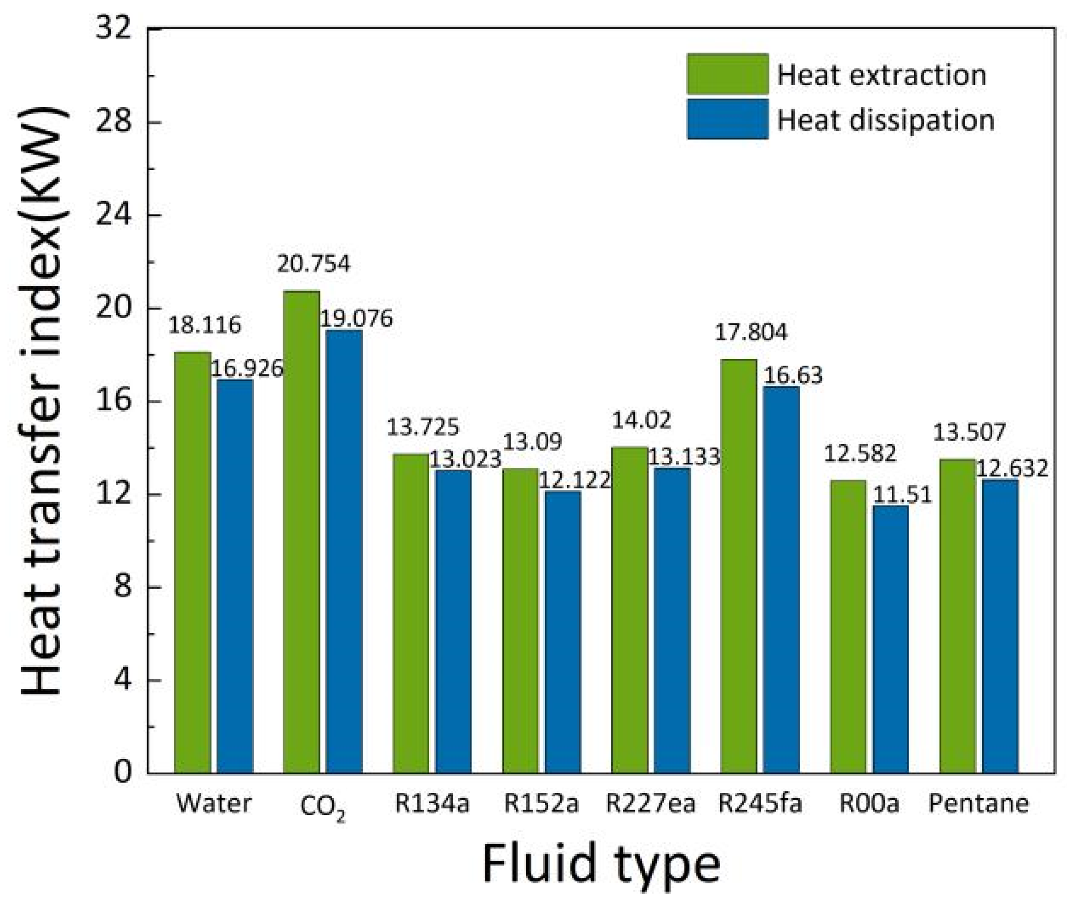
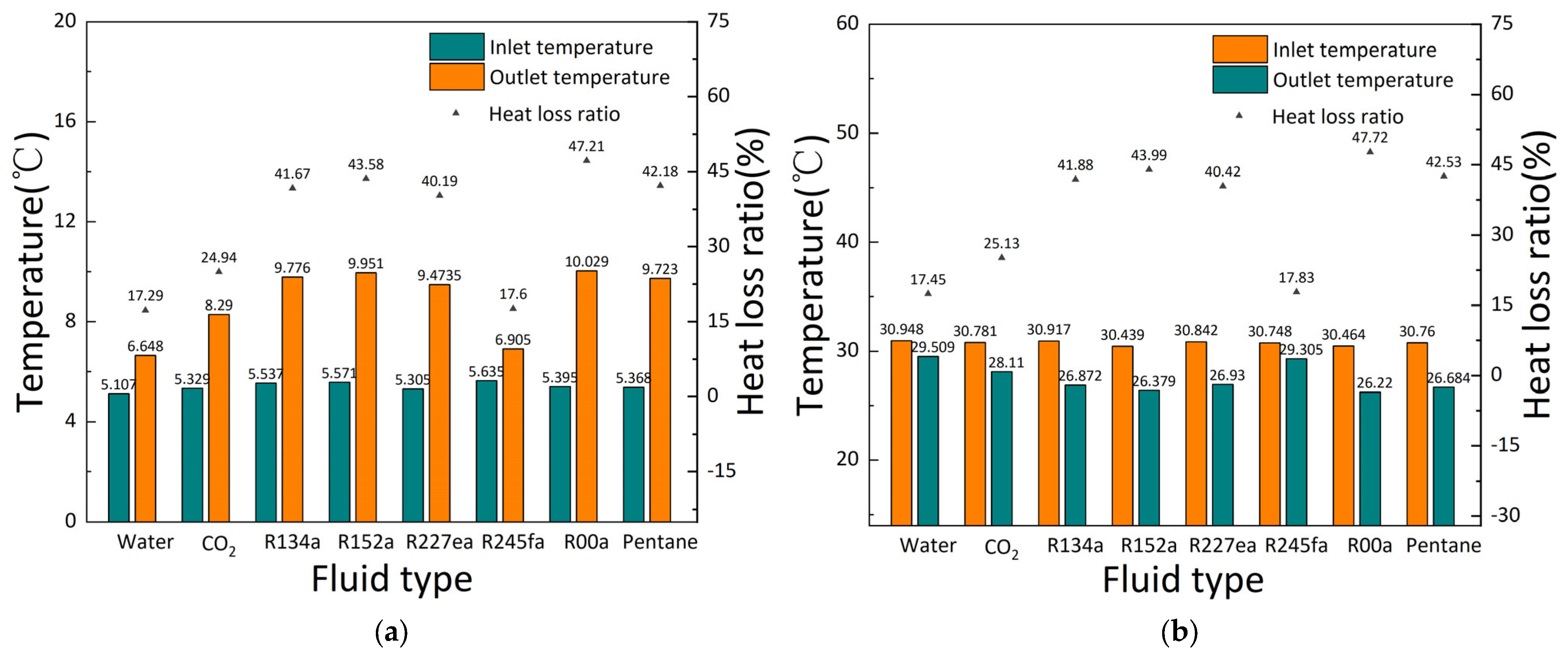
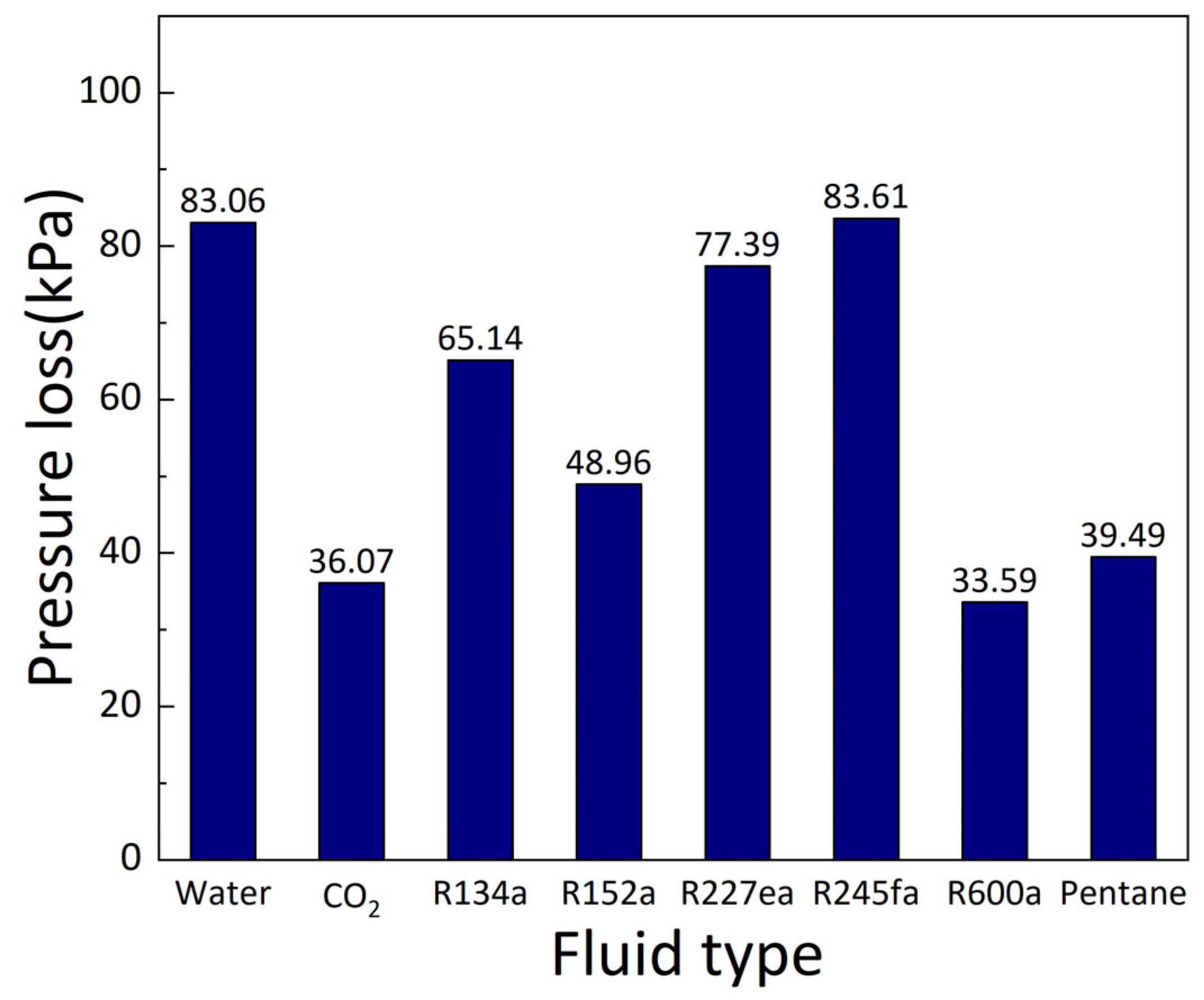
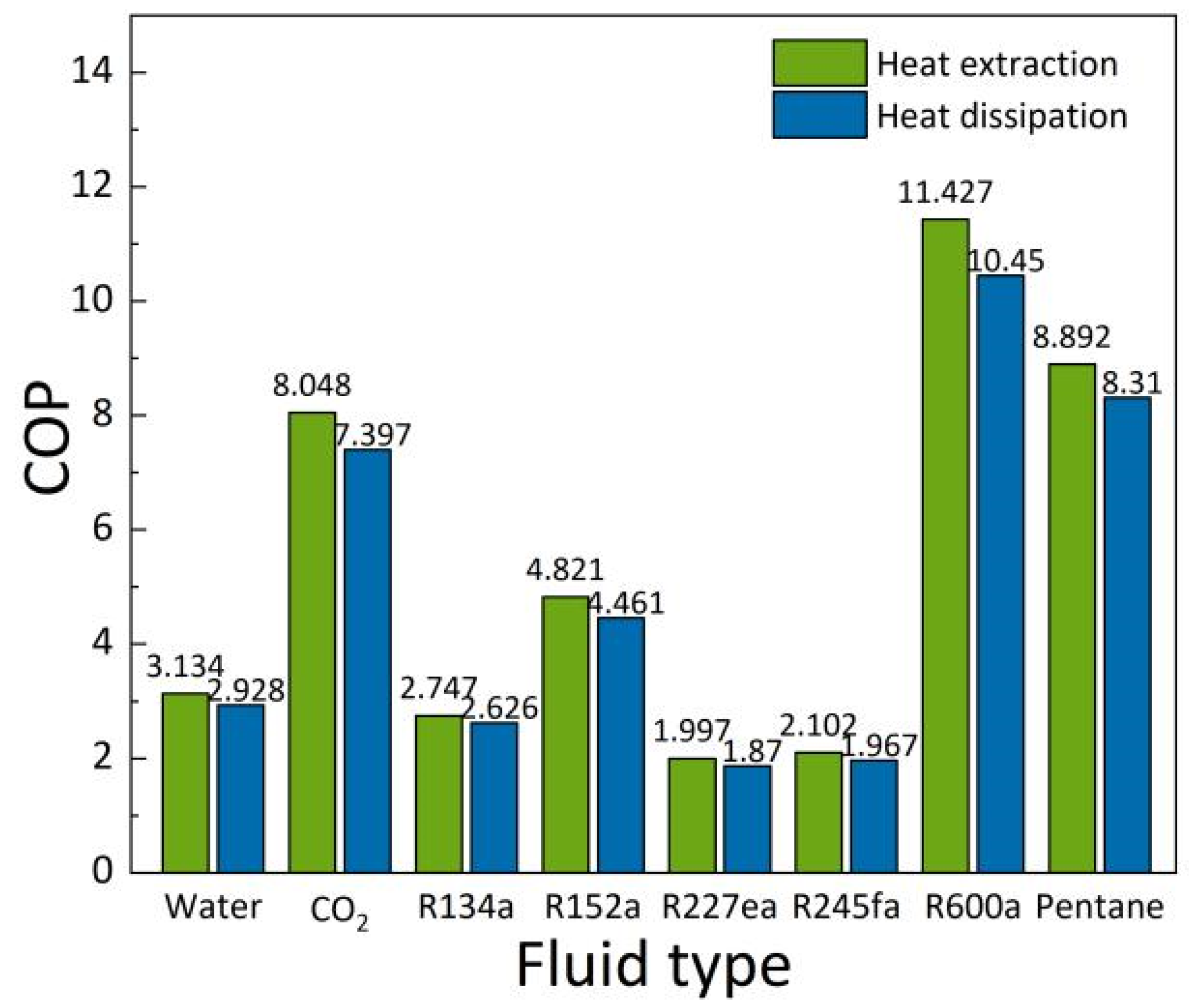
This article defined a quantitative indicator called the “heat transfer index” to represent the heat transfer capacity of BGHEs. CO2 provided the highest heat transfer, followed by water. Moreover, it was found that when the burial depth of the borehole reached 300 m, its heating capacity was higher than its cooling capacity. After four months of continuous operation, R600a exhibited the highest outlet temperature during the winter. However, the heat loss rate was also the highest. Due to the higher dynamic viscosity coefficient of water, it results in a larger pressure loss, with a value of 83.06 kPa. Therefore, from the analysis of the heat transfer performance and pump power consumption, R600a and CO2 were more suitable than water.
(3)
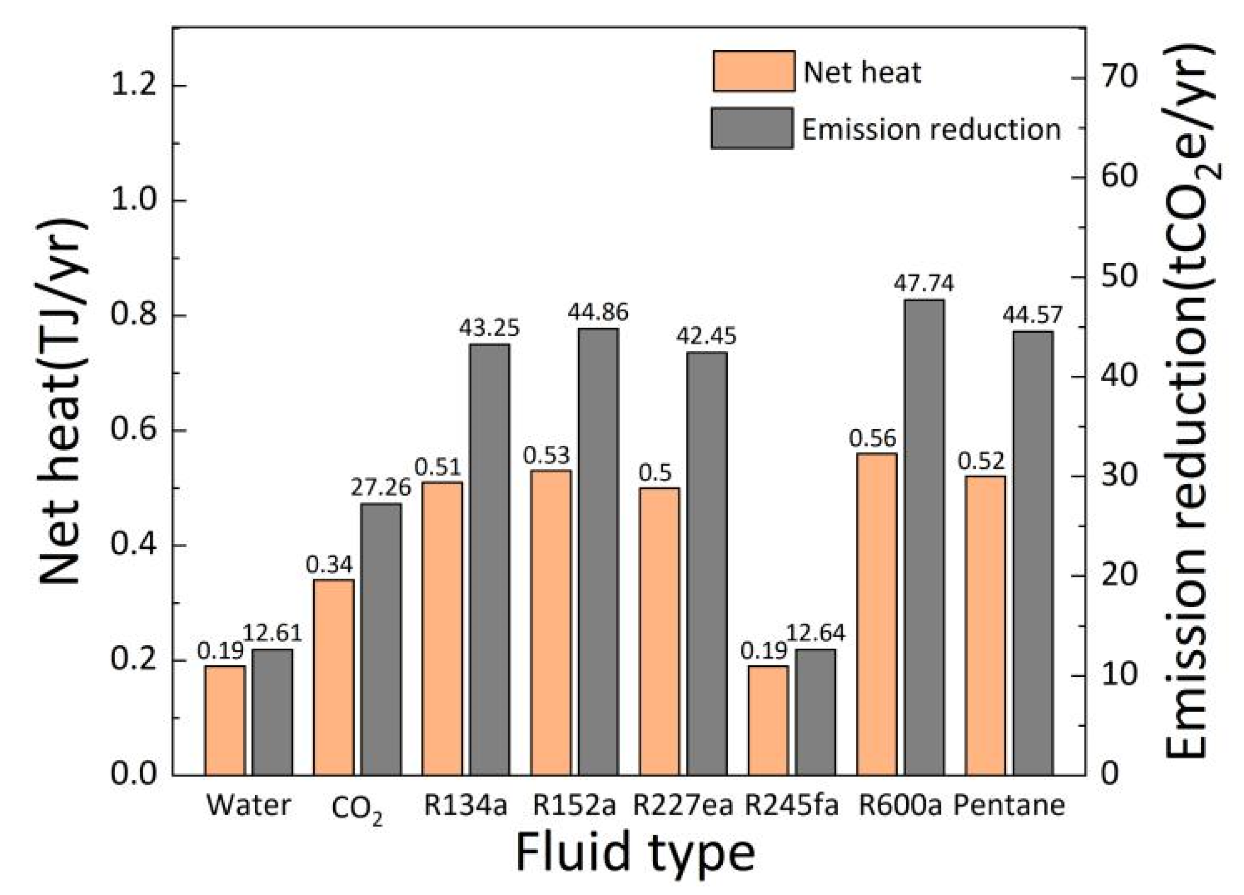
The effect of the working fluid type on the environmental benefits and carbon reduction potential of medium-shallow BGHEs was studied. It was found that R600a, R134a, pentane, and CO2 all showed excellent environmental benefits, while the annual emission reduction and net heat of water was the lowest, and their values were 44.11% and 53.74% lower than CO2, respectively. Especially when CO2 was selected as the working fluid, the carbon emissions into the atmosphere by CO2 emission sources such as thermal power plants could be reduced. Finally, combined with economic analysis, CO2 yielded the lowest investment cost and the shortest payback period among the various organic working fluids in this paper.
(4)
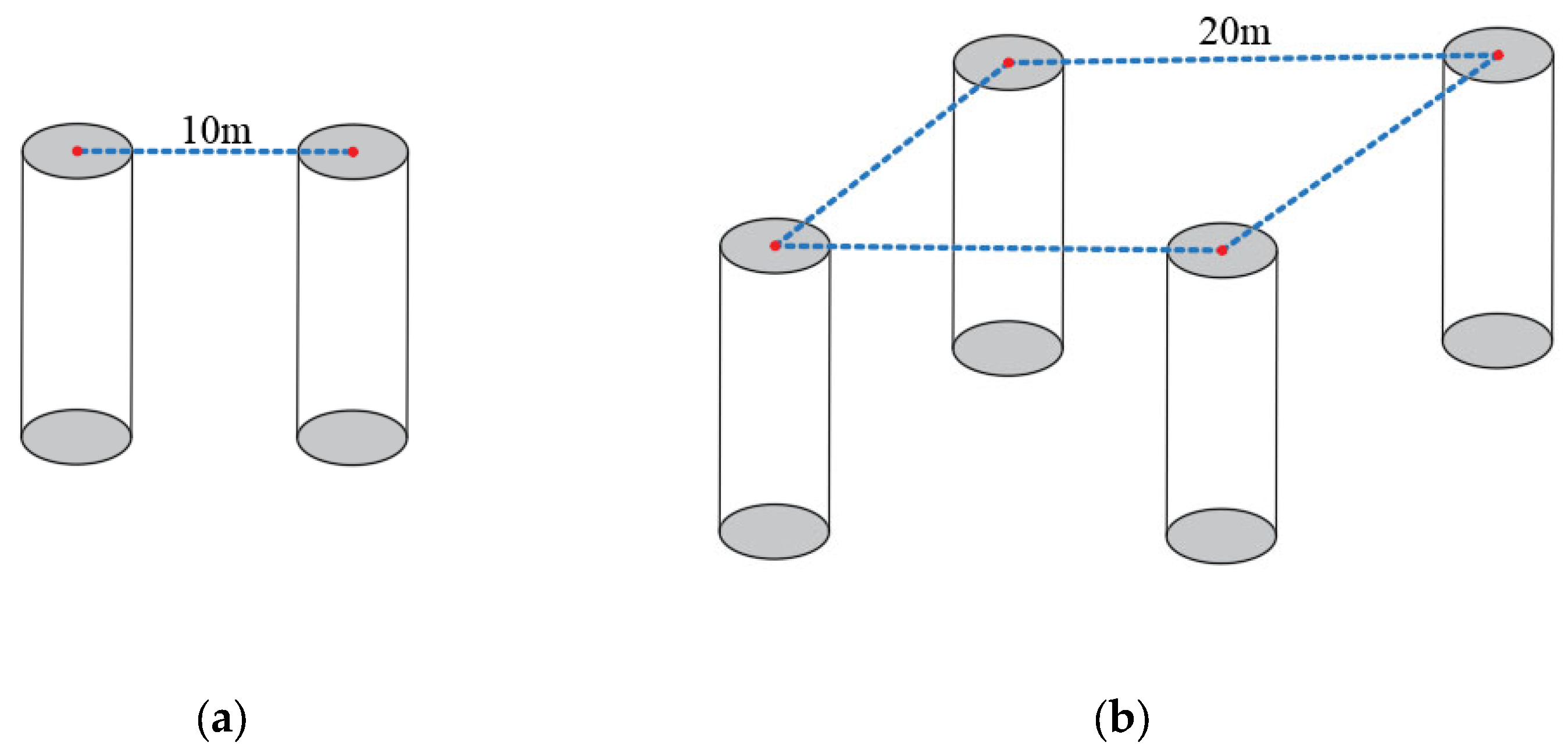
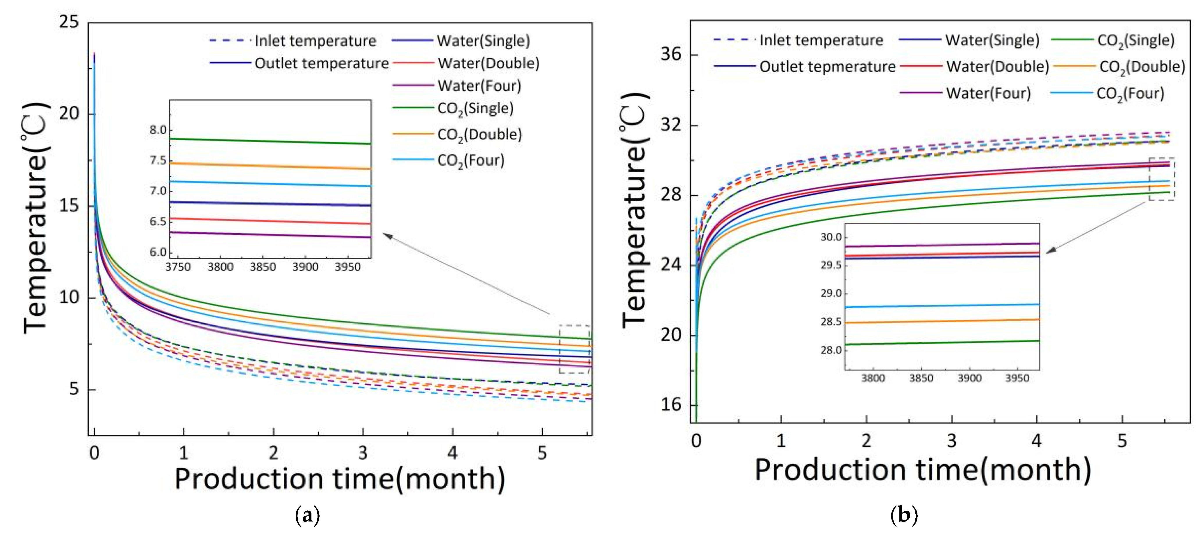
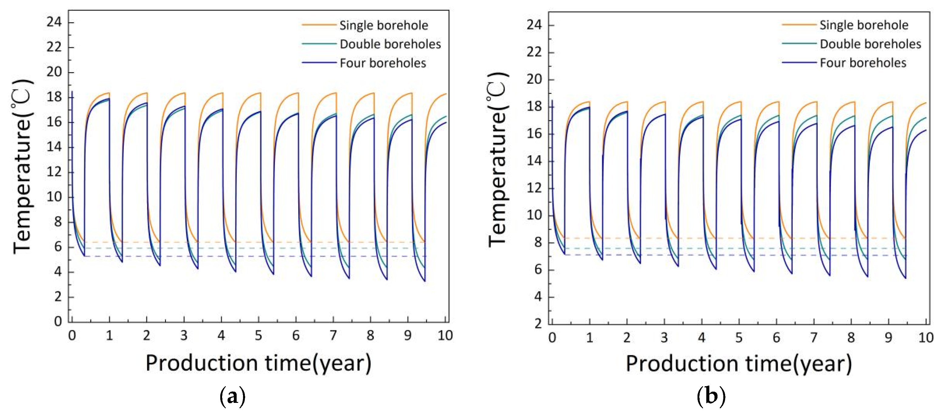
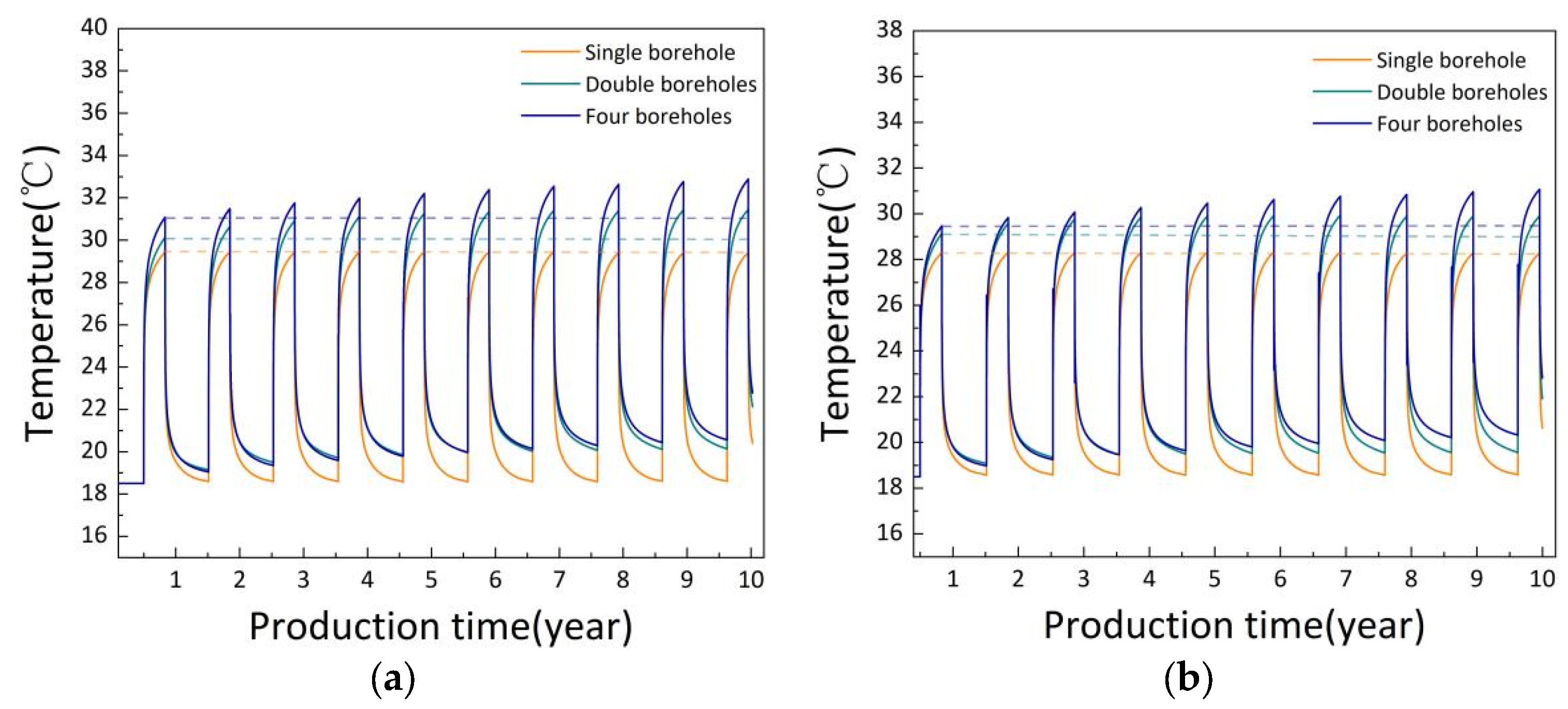
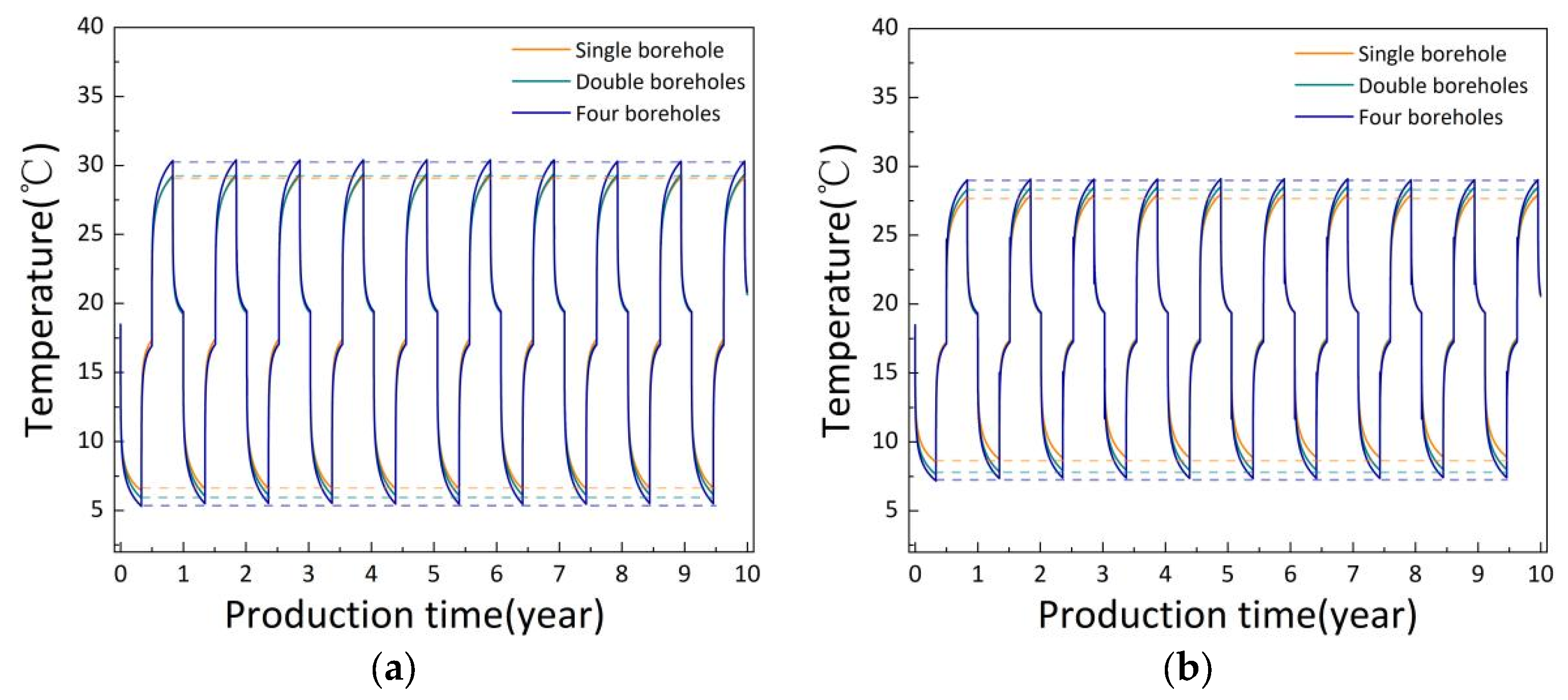
The number of boreholes significantly affected the outlet temperature of the working fluid of BGHEs. In the heat extraction mode, when CO2 was selected as the working fluid for BGHEs and operated for 10 years, the outlet temperature was reduced by approximately 6% for the two-borehole form and by approximately 10% for the four-borehole form relative to the single-borehole form. The thermal interference between the BGHEs and the imbalance between the soil cooling and heating loads should be noted. It is recommended to activate the heat extraction mode during the winter season and the heat dissipation mode during the summer season.
This work contributes to understanding the effect of the working fluid type and numbers of boreholes on the heat transfer characteristics of medium-shallow BGHEs. In this study, the working fluid inside the BGHE is constantly considered as a liquid. Therefore, the future research direction focuses on investigating the effect of inlet pressure and phase change of the working fluid on the heat performance of the BGHEs.

Author Contributions

Conceptualization, K.W.; validation, Z.Z., X.M. and L.Z.; writing—original draft preparation, K.W.; writing—review and editing T.H. and W.Z. All authors have read and agreed to the published version of the manuscript.

Funding

This research was funded by the Natural Science Foundation of Shandong Province, China, grant number [NO. ZR2022ME079].

Institutional Review Board Statement

The study did not require ethical approval.

Informed Consent Statement

Not applicable.

Data Availability Statement

Not applicable.

Acknowledgments

The work described in this paper was supported by the Natural Science Foundation of Shandong Province, China (NO. ZR2022ME079).

Conflicts of Interest

The authors declare no conflict of interest.

Appendix A

In the process of verifying the accuracy of the numerical model developed in this paper, the relative error has been introduced, and its calculation method is shown below:
α Re = T s T e T e × 100 %
where αRe is the relative error; Ts is the simulated inlet and outlet temperatures, ℃; and Te is the experimental inlet and outlet temperatures, ℃.

References

  1. Li, Q.; Wang, F.L.; Wang, Y.L.; Zhou, C.; Chen, J.; Forson, K.; Miao, R.; Su, Y.; Zhang, J. Effect of reservoir characteristics and chemicals on filtration property of water-based drilling fluid in unconventional reservoir and mechanism disclosure. Environ. Sci. Pollut. Res. 2023, 30, 55034–55043. [Google Scholar] [CrossRef] [PubMed]
  2. Sönnichsen, N. Daily Demand for Crude Oil Worldwide from 2006 to 2020, with a Forecast Unit 2026. 2021. Available online: https://www/statista.com/statistics/271823/daily-global-crude-oil-demand-since-2006/ (accessed on 6 June 2023).
  3. Li, Q.; Zhao, D.; Yin, J.; Zhou, X.; Li, Y.; Chi, P.; Han, Y.; Ansari, U.; Cheng, Y. Sediment instability caused by gas production from hydrate-bearing sediment in Northern South China Sea by horizontal wellbore: Evolution and Mechanism. Nat. Resour. Res. 2023, 32, 1595–1620. [Google Scholar] [CrossRef]
  4. Wang, Y.Q.; Liu, Y.X.; Dou, J.Y.; Li, M.Z.; Zeng, M. Geothermal energy in China:status, challenges, and policy recommendations. Util. Pol. 2020, 64, 101020. [Google Scholar] [CrossRef]
  5. Lyu, W.H.; Li, X.T.; Wang, B.L.; Shi, W.X. Energy saving potential of fresh air pre-handling system using shallow geothermal energy. Energy Build 2019, 185, 39–48. [Google Scholar] [CrossRef]
  6. Ma, B.; Jia, L.X.; Yu, Y.; Wang, H. The development and utilization of geothermal energy in the world. Geol. China 2021, 48, 1734–1747. [Google Scholar]
  7. Chen, S.Y.; Zhang, Q.; Li, H.L.; Mclellan, B.; Zhang, T.T.; Tan, Z.Z. Investment decision on shallow geothermal heating & cooling based on compound options model: A case study of China. Appl Energy 2019, 254, 113655. [Google Scholar]
  8. Omer, A.M. Ground-source heat pumps systems and applications. Renew. Sustain. Energy Rev. 2008, 12, 344–371. [Google Scholar] [CrossRef]
  9. Rybach, L.; Hopkirk, R.J. Shallow and deep borehole heat exchangers-Achievements and prospects. In Proceedings of the World Geothermal Congress, International Geothermal Association, Florence, Italy, 18–31 May 1995; pp. 2133–2138. [Google Scholar]
  10. Ingersoll, L.R.; Zobel, O.J.; Ingersoll, A.C. Heat Conduction with Engineering, Geological, and Other Applications; University of Wisconsin Press: Madison, WI, USA, 1954; pp. 66–78. [Google Scholar]
  11. Zeng, H.Y.; Diao, N.R.; Fang, Z.H. A model of finite-length linear heat-source for the vertical embedded pipe of a ground-source heat pump. Eng. Therm. Energy Power 2003, 2, 166–170+216. [Google Scholar]
  12. Tranter, C.J. Conduction of Heat in Solids, 2nd ed.; Clarendon Press: Oxford, UK, 1959. [Google Scholar]
  13. Diao, N.R.; Zeng, H.Y.; Fang, Z.H. Improvement on modelling of heat transfer in vertical ground heat exchanger. Int. J. HVACR Res. 2004, 10, 450–470. [Google Scholar]
  14. Zeng, H.; Diao, N.; Fang, Z. Heat transfer analysis of boreholes in vertical ground heat exchangers. Int. J. Heat Mass Transf. 2003, 46, 4467–4481. [Google Scholar] [CrossRef]
  15. Mahmoodpour, S.; Singh, M.; Turan, A.; Bär, K.; Sass, I. Simulations and global sensitivity analysis of the thermo-hydraulic-mechanical processes in a fractured geothermal reservoir. Energy 2022, 247, 123511. [Google Scholar] [CrossRef]
  16. Amiri, D.A.; Sajjadi, H.; Ahmadi, G. The Effect of Piezoelectric Transducer Location on Heat Transfer Enhancement of an Ultrasonic-Assisted Liquid-Cooled CPU Radiator. Iran. J. Sci. Technol. Trans. Mech. Eng. 2023, 1–14. [Google Scholar] [CrossRef]
  17. Lyu, Z.; Song, X.; Li, G.; Hu, X.; Shi, Y.; Xu, Z. Numerical Analysis of Characteristics of a Single U-tube Downhole Heat Exchanger in the Borehole for Geothermal Wells. Energy 2017, 125, 186–196. [Google Scholar] [CrossRef]
  18. Li, J.; XU, W.; Li, J.F. Heat supply technology review and engineering measurement analysis of medium and deep buried pipes. Heat. Vent. Air Cond. HVAC 2020, 50, 35–39. [Google Scholar]
  19. Deng, J.; Wei, Q.; He, S.; Liang, M.; Zhang, H. Simulation analysis on the heat performance of deep borehole heat exchangers in medium-depth geothermal heat pump systems. Energies 2020, 13, 754. [Google Scholar] [CrossRef]
  20. Welsch, B.; Rühaak, W.; Schulte, D.O. Characteristics of medium deep borehole thermal energy storage. Int. J. Energy Res. 2016, 40, 1855–1868. [Google Scholar] [CrossRef]
  21. Cai, W.; Wang, F.; Chen, S.; Chen, C.; Liu, J.; Deng, J.; Kolditz, O.; Shao, H. Analysis of heat extraction performance and long-term sustainability for multiple deep borehole exchanger array: A project-based study. Appl. Energy 2021, 289, 116590. [Google Scholar] [CrossRef]
  22. Yu, M.; Lu, W.; Zhang, F.; Zhang, W.; Cui, P.; Fang, Z.H. A novel model and heat extraction capacity of mid-deep buried U-bend pipe ground heat exchangers. Energy Build. 2021, 235, 110723. [Google Scholar]
  23. Yuan, Y.P.; Lei, B.; Yu, N.Y.; Cao, X.L.; Zhang, D. Heat transfer of ground heat exchange for GSGP(1): A review. Heat. Vent. Air Cond. HVAC 2008, 38, 25–31. [Google Scholar]
  24. Saeed, M.; Mrityunjay, S.; Kristian, B.; Sass, B. Thermo-hydro-mechanical modeling of an enhanced geothermal system in a fractured reservoir using carbon dioxide as heat transmission fluid-A sensitivity investigation. Energy 2022, 254, 124266. [Google Scholar]
  25. Mrityunjay, S.; Saeed, M.; Reza, E.; Soltanian, M.R.; Sass, I. Comparative study on heat extraction from Soultz-sous-Forêts geothermal field using supercritical carbon dioxide and water as the working fluid. Energy 2023, 266, 126388. [Google Scholar]
  26. Wang, X.; Yao, H.; Li, J. Experimental and numerical investigation on heat transfer characteristics of ammonia thermosyhpons at shallow geothermal temperature. Int. J. Heat Mass Tran. 2019, 136, 1147–1159. [Google Scholar] [CrossRef]
  27. Pumaneratkul, C.; Yamasaki, H.; Yamaguchi, H. Supercritical CO2 Rankine cycle system with low-temperature geothermal heat pipe. Energy Procedia 2017, 105, 1029–1036. [Google Scholar] [CrossRef]
  28. Yildirim, N.; Parmanto, S.; Akkurt, G.G. Thermodynamic assessment of downhole heat exchangers for geothermal power generation. Renew. Energy 2019, 141, 1080–1091. [Google Scholar] [CrossRef]
  29. Shi, Y.; Bai, Z.; Feng, G.; Tian, H.; Bai, H. Performance analysis of medium-depth coaxial heat exchanger geothermal system using CO2 as a circulating fluid for building heating. Arab. J. Geosci. 2021, 14, 1308. [Google Scholar] [CrossRef]
  30. Tchanche, B.F.; Papadakis, G.; Lambrinos, G.; Frangoudakis, A. Fluid selection for a low-temperature solar organic Rankine cycle. Appl. Therm. Eng. 2009, 29, 2468–2476. [Google Scholar] [CrossRef]
  31. Zhang, T.A.; Wang, R.F.; Wang, F.H. Influence of sustainable load imbalance ratio of heat exchanger of medium-shallow borehole. Pet. Reserv. Eval. Dev. 2022, 12, 886–893. [Google Scholar]
  32. Diao, N.R.; Fang, Z.H. ; Ground-Coupled Heat Pump Technology; Higher Education Press: Beijing China, 2006. [Google Scholar]
  33. Zhang, F.; Fang, L.; Jia, L.; Man, Y.; Cui, P.; Zhang, W.; Fang, Z. A dimension reduction algorithm for numerical simulation of multi-borehole heat exchangers. Renew. Energy 2021, 179, 2235–2245. [Google Scholar]
  34. Gong, G.C. Fluid Transfer Nets; China Machine Press: Beijing, China, 2018.
  35. Phillipp, H.; Olaf, K.; Uwe-Jens, G.; Anke, B.; Shao, H. A numerical study on the sustainability and efficiency of borehole heat exchanger coupled ground source heat pump systems. Appl. Therm. Eng. 2016, 100, 421–433. [Google Scholar]
  36. United Nations Framework Convention on Climate Change Executive Board. Fossil Fuel Displacement by Geothermal Resources for Space Heating. Available online: https://cdm.unfccc.int/methodologies/index.html (accessed on 6 June 2023).
Figure 1. Schematic diagram of the casing borehole heat exchanger.
Sustainability 15 12657 g001
Figure 2. Schematic diagram of the grid of the casing-type borehole heat exchanger.
Sustainability 15 12657 g002
Figure 3. Schematic diagram of the radial section grid of the casing drilling group.
Sustainability 15 12657 g003
Figure 4. Schematic diagram of the experimental process.
Sustainability 15 12657 g004
Figure 5. Comparison of the simulated data with the experimental data.
Sustainability 15 12657 g005
Figure 6. Heat transfer indexes of different types of working fluids in the heat extraction and heat dissipation modes.
Sustainability 15 12657 g006
Figure 7. Inlet and outlet temperatures of different types of working fluids in two modes. (a) Heating mode. (b) Cooling mode.
Sustainability 15 12657 g007
Figure 8. Inlet and outlet temperatures and heat loss rates of different types of working fluids in the two modes. (a) Heating mode. (b) Cooling mode.
Sustainability 15 12657 g008
Figure 9. Pressure loss of different types of working fluids.
Sustainability 15 12657 g009
Figure 10. COP of different types of working fluids in the heat extraction and heat dissipation modes.
Sustainability 15 12657 g010
Figure 11. Net heat and emission reductions of different types of working fluids.
Sustainability 15 12657 g011
Figure 12. The relative positions of the boreholes of the borehole group. (a) Double boreholes. (b) Four boreholes.
Sustainability 15 12657 g012
Figure 13. Inlet and outlet temperature variations of the working fluid in the borehole heat exchanger with one, two, and four boreholes in two modes. (a) Heating mode. (b) Cooling mode.
Sustainability 15 12657 g013
Figure 14. The outlet temperature of the working fluid of the BGHEs changes within 10 years when only the heat extraction mode is turned on. (a) Water. (b) CO2.
Sustainability 15 12657 g014
Figure 15. Changes in the outlet temperature of the working fluid of the BGHEs within 10 years when only the heat dissipation mode is turned on. (a) Water. (b) CO2.
Sustainability 15 12657 g015
Figure 16. The outlet temperature of the working fluid of the BGHEs changes within 10 years when both the heat extraction and heat dissipation modes are turned on. (a) Water. (b) CO2.
Sustainability 15 12657 g016
Table 1. Experimental parameters.
Parameter/UnitSymbolNumerical Value
Drilling depth/(m)H300
Heating power/(kW)Q19
Circulating flow/(m3/h)F3.5
Import and outlet temperature difference of the circulating fluid (°C)Δt4.5
Drilling diameter/(m)dbo0.133
Outer tube outer diameter/(m)d1o0.108
Outer tube inner diameter/(m)d1i0.099
Outer tube surface roughness/(mm)k10.046
Inner tube outer diameter/(m)d2o0.063
Inner tube inner diameter/(m)d2i0.0526
Inner tube surface roughness/(mm)k20.0015
Geotechnical thermal conductivity/(W/(m·°C))λg2.09
Thermal conductivity of outer tube/(W/(m·°C))λ145
Thermal conductivity of inner tube/(W/(m·°C))λ20.24
Thermal conductivity of backfill material/(W/(m·°C))λb1.83
Volume specific heat capacity of soil/(J/(m3·°C))Cg2.46 × 106
Volume specific heat capacity of outer tube/(J/(m3·°C))C13.45 × 106
Volume specific heat capacity of inner tube/(J/(m3·°C))C21.9 × 106
Volume specific heat capacity of backfill material/(J/(m3·°C))Cb2.42 × 106
Volume specific heat capacity of working fluid/(J/(m3·°C))Cw4.187 × 106
Table 2. Critical pressure and critical temperature of the working fluid.
Working FluidCritical Pressure/(MPa)Critical Temperature/(°C)
Water22.05374.3
CO27.231.2
R134a (1,1,1,2-tetrafluoroethane)4.067101.1
R152a (1,1-difluoroethane)4.54113.45
R227ea (1,1,1,2,3,3,3-heptafluoropropane)2.98102.8
R245fa (1,1,1,3,3-pentafluoropropane)3.651154
R600a (isobutane)3.648134.9
Pentane3.37196.5
Table 3. Displacement calculation parameters.
ParameterNumerical Value
Heating area/(m2)1000
Thermal index/(W/m2)50
Total heating season heating hours /(h)2880
Average geothermal water flow in heating season /(m3/h)25
Table 4. Working fluid price parameters.
Working FluidUnit Price/(CNY/kg)Initial Investment in Circulating Fluid/Ten Thousand CNY)
water0.00410.001383
CO20.180.0492
R134a24.510.37
R152a16.55.17
R227ea115.37
R245fa6027.72
R600a10019.18
pentane9019.23
Disclaimer/Publisher’s Note: The statements, opinions and data contained in all publications are solely those of the individual author(s) and contributor(s) and not of MDPI and/or the editor(s). MDPI and/or the editor(s) disclaim responsibility for any injury to people or property resulting from any ideas, methods, instructions or products referred to in the content.

