Article

Reacquainting the Structural Characteristics of Pull-Apart Basins Based on Simulations with Wet Clay

1
State Key Laboratory of Oil and Gas Reservoir Geology and Exploitation, Chengdu University of Technology, Chengdu 610059, China
2
College of Mining Engineering, North China University of Science and Technology, Tangshan 063210, China
3
No. 6 Oil Production Plant of Daqing Oil Field Co., Ltd., Daqing 163114, China
*
Author to whom correspondence should be addressed.
Sustainability 2023, 15(19), 14143; https://doi.org/10.3390/su151914143
Submission received: 3 July 2023 / Revised: 17 August 2023 / Accepted: 25 August 2023 / Published: 25 September 2023
(This article belongs to the Special Issue Basin Tectonic Analysis and Geoenergy Exploration)

Abstract

:
A pull-apart basin (PAB) is a releasing zone constrained by strike–slip faults. A PAB partly appears as a unique basin type typically dominated by the basin sidewall and cross-basin faults. However, the structural characteristics of different subsidiary faults derived from strike–slip motions are currently poorly understood in PABs. Under the control of different bend strike–slip faults, this study examines the formation and evolution of PABs reconstructed from wet clay with high water content (68%) as the experimental material. It was reported that (1) a PAB shows the single asymmetric half-graben architecture in the profile and rhombus in the plane, regardless of the bend type of the strike–slip fault; (2) the subsidiary fault area density increases with increasing fault displacement in PABs and might be impacted by the nature of the wet clay; (3) as the strike–slip fault displacement increases, the subsidiary fault number initially increases and then begins to decrease with large fault formation; and (4) T-faults are the most numerous faults in PABs, followed by Riedel shear faults. R′- and P-shear faults account for a small proportion and are unstable. The proportion of Riedel shear faults gradually decreases from the underlapping strike–slip faults to the overlapping strike–slip faults, accompanied by an increase in the corresponding R′-shear faults. The primary control factor affecting the proportion of subsidiary faults is the stress component. Re-recognition of subsidiary faults in the PABs is significant for interpreting strike–slip faults and the study of hydrocarbon migration.

1. Introduction

As large strike–slip faults can easily cut the Earth’s crust, they can directly affect the formation and evolution of plates [1,2,3,4,5]. Moreover, they also cause local or regional contractions and extensions, forming unique basin–mountain assemblages. Therefore, large strike–slip faults, such as the San Andreas and Philippine faults, are important seismic zones related to tectonic plates. Basins associated with strike–slip faults, such as the Aerjin and Tan-Lu faults, are of particular interest because they typically form unique ore-bearing belts [6,7].
A pull-apart basin (PAB) is a releasing zone in the bend (jog) or stepover (offset) between two primary strike–slip faults or fault segments [8]. Typically, a PAB is constrained by the strike–slip fault and its related subsidiary faults. Such a basin is called a special linking damage that is oblique or transverse to the primary strike–slip fault or fault segment [9,10,11,12]. Depending on their offset angle, strike–slip fault connections can be categorized into three types: underlapping, neutral, and overlapping [13]. These types restrain the boundary and morphology of the PAB; consequently, PABs demonstrate rhomboid, lazy-Z, or spindle shapes from the overlapping primary fault to the underlapping primary fault [13,14]. The profile morphology of a PAB differs from the flower structure in the primary strike–slip fault (the principal displacement zone (PDZ)) because it is affected not only by the primary strike–slip fault but also by the subsidiary “V” shape in the underlapping strike–slip fault and the “U” and box types in the neutral and overlapping strike–slip faults [15]. Furthermore, the subsidence depths of PABs differ at the same displacement, being the largest for a PAB of the overlapping strike–slip fault, followed by a neutral and an underlapping strike–slip fault [16]. PABs of the underlapping and overlapping of the strike–slip faults frequently exhibit two subsidence centers [17].
The composition and evolution of subsidiary faults in a PAB differ from those of faults in other basins. The Riedel shear, R′-shear, P-shear, and T-faults in a PAB are derived from stress fields generated by strike–slip motions [18], but they have different strikes and formation times. A Riedel shear fault develops in the early evolution stage and then transforms into a basin sidewall fault to control the PAB architecture. Usually, the Riedel shear fault connects and merges with a P-shear fault in the late stage, thus forming the PDZ [9,13]. When a Riedel shear fault couples with an R′-shear fault, the two faults move in opposite directions; however, R′-shear faults are uncommon. In general, the strike of a subsidiary fault strike with strike–slip composition is related to the internal friction angle between the rock and the local stress field.
The number of subsidiary faults in a PAB is affected by multiple factors: the strike–slip displacement, the movement velocity of the strike–slip fault, the rock mechanical property, and the stepover or bend type of the strike–slip fault [8,19,20]. In experiments, the number of subsidiary faults depends on the experimental material and is commonly smaller in quartz sand than in wet clay. The stepover degree of a primary strike–slip fault is not significantly correlated with the number of subsidiary faults in a PAB [21]. The subsidiary fault number increases with an increase in displacement of the primary strike–slip fault, regardless of the stepover or bend type of the primary strike–slip fault.
As reported previously, subsidiary faults (Riedel’, R′-P-shear, and T-faults) can appear in a primary strike–slip zone [22]. Two questions arise: (1) how do different types of subsidiary faults affect a PAB controlled by different bend types of strike–slip faults, and (2) what type of strike–slip fault dominates the subsidiary fault number and density in a PAB? Wet clay is selected as the experimental material because more multiple subsidiary faults can be generated and evenly distributed in the wet clay model compared to the sandstone model. Meanwhile, fault propagation is slower in the wet clay model; thus, the fault can be easily recorded and observed. Based on a series of wet clay simulations, we systematically clarify the features of multiple subsidiary faults in PABs controlled by strike–slip faults with different bend types and demonstrate our results with an example. This recognition will assist the study of PABs related to the subsidiary of the strike–slip faults.

2. Experimental Design and Statistics

2.1. Experimental Design

The experiment was designed similarly to that of Corti et al. in the movement mode and the arrangement of the strike–slip faults [13,17] (Figure 1). Our experimental model was composed of two strike–slip faults with sinistral motion and a left-stepping configuration, where the separations between the strike–slip faults and the fault displacement in the three group experiments were 3 and 2.6 cm, respectively, which are different from those in the previous experiment. The northern base plate was set close to the southern base plate to complete the pure strike–slip activity, and the southern base plate was fixed.
Based on the previous scaling demonstration, the geometric and kinematic similarity need to be satisfied in this study [13].
C* = ρ*  ·  g*  ·  L*
where C*, ρ*, g*, and L* represent the cohesive strength, density, gravity, and length between the model and nature, respectively; g* = 1 at normal gravity, g* is 0.56 to 0.68 under the condition of the upper crust average density 2.5 g/cm3, and the cohesion value of intact sedimentary rock is ~20 MPa [14].
The dynamic similarity was achieved with geometrical similarity and similar boundary conditions; thus, only the movement time or velocity was satisfied. In this study, the wet mud density was 1.65 g/cm3 when its water content was 68%. If a reasonable geometrical ratio of 10−6 is selected, 1 cm in the model corresponds to 10 km in nature; the moving velocity of our model was 0.008 mm/s, i.e., it takes 40 Ma to form a fault that is 10 km long or displacement in the Cenozoic clastic rocks.

2.2. Experimental Material

Physical experiments related to strike–slip motions provide insights into the characteristics of PABs [9,18]. The experimental material is typically wet clay [8,23], sand [14,17], or another suitable material [8,9,14]. The most commonly used materials (quartz sand and wet clay) have different experimental mechanisms. In quartz sand models, the shape is controlled by the friction between the quartz particles [24]. Moreover, the physicochemical effects of water among the particles in wet clay directly affect the deformation process [23]. Because wet clay is highly malleable, it has been popular in studies of fault strikes, fault numbers, fault density, and structural subsidence (Table 1). In contrast, wet clay with a water content of 68% can form larger fault numbers under smaller structural subsidence (Figure 2). In this study, the subsidence depth of wet mud was continuously measured using a ruler during the experiment; however, it exhibits a clear disadvantage in that only a fixed point depth can be measured.

2.3. Fault Area Density Statistics

The structural deformation during the present experiment was recorded by a camera on top of the experimental model. The faults (including fractures) were interpreted by unscrambling the camera pictures. After overlaying a 0.5 × 0.5 cm grid on the structural model, 1416 grids were created in each experimental model. The fault area density was obtained by adding the fault numbers in each grid.
The total number of faults in each grid is directly related to the fault area density; however, the correlation between the number of faults and the total fault displacement is not obvious. A fault with a large displacement often develops via the connection of nearby smaller faults, thus resulting in an obviously low fault area density in the vicinity of the large fault. In locations of high fault area density, the large number of faults may favor the development of a large fault.

2.4. Division of Subsidiary Faults

In a strike–slip fault zone, the position of the subsidiary fault is relatively fixed, and the Riedel, R′-, and P- shear faults are related to the internal friction angle of the experiment materials and belong to the strike–slip fault category. In particular, the Riedel, R′-, and P-shear faults are angled at φ/2, 45°, 90° − φ/2, and 180° − φ/2 (where φ is the internal friction angle) compared to the PDZ [22]. Therefore, the internal friction angle of the experimental material directly affects the strike of these subsidiary faults. In the wet clay model, a large number of oblique slip faults develop between the strike–slip faults and normal faults in the PAB, which should be grouped into their adjacent subsidiary faults. In this experiment, the strike ranges of the Riedel shear fault, R′-shear fault, P-shear fault, and T-fault were φ/2 ± 15°, 45° ± 15°, 90° − φ/2 ± 15°, and 180° − φ/2 ± 15°, respectively. The fault number within the overlap range of these subsidiary faults was small and could safely be ignored [14].

3. Experimental Results

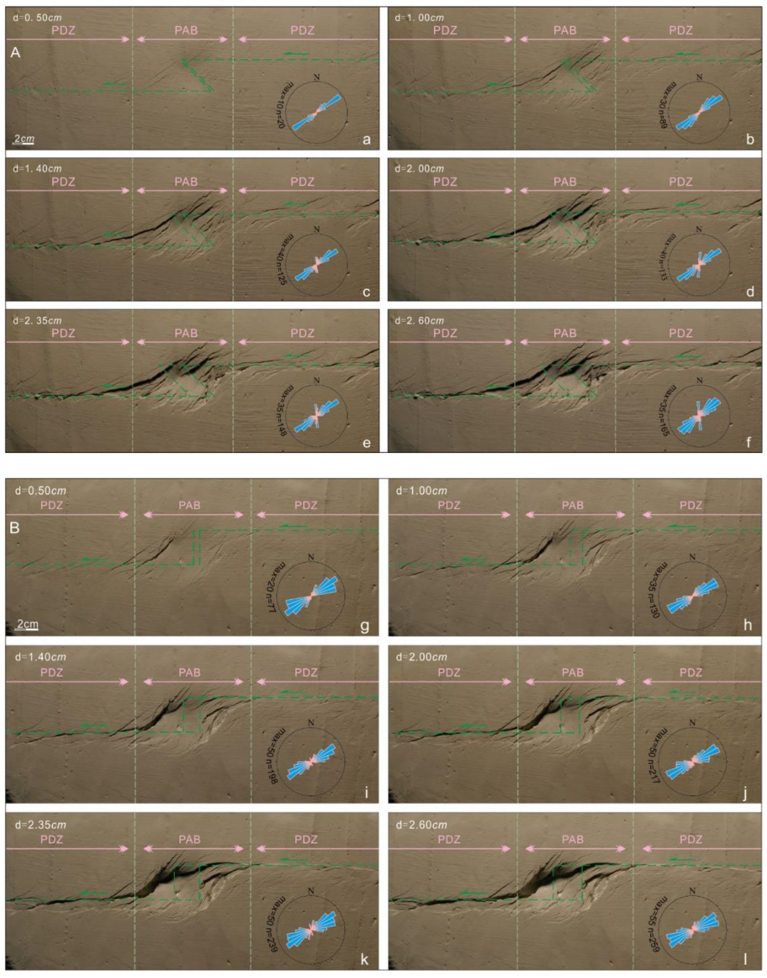
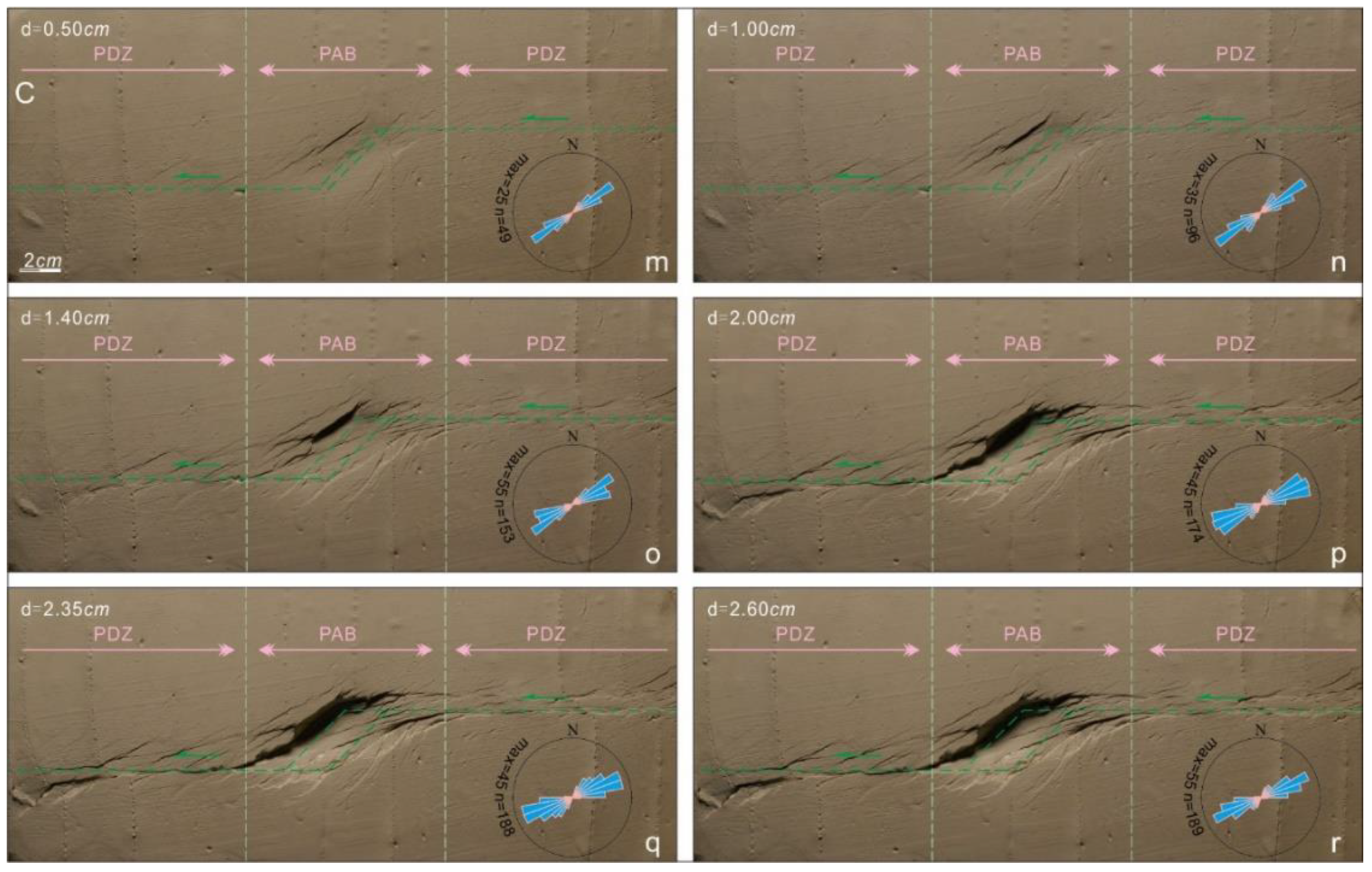
3.1. Evolution of a Strike–Slip Fault with Different Bends

In all modeling experiments, the strike–slip fault zone was characterized by a gradual increase in fault number (including fracture number) as the mobile plate moved (Figure 3). The fault with the maximum heave in the PAB, often called the basin sidewall fault, commonly appears on the side of the mobile plate [9,17]. In the present modeling experiments, the fault with the maximum horizontal separation always occurred on the PDZ. Moreover, the so-called cross-basin faults with the longest fault length (almost spanning the entire PAB) were found.
With the evolution processes with continuous strike–slipping, the subsidiary faults (Riedel, R’-, P-shear, and T-faults) demonstrated obvious differences in their strikes and time sequences [18]. The Riedel shear fault appeared first and in greater numbers than the other fault types on the overall PDZ. The R′-shear fault with an approximate SN strike rapidly increased in the middle–late evolution stage on the PAB, being controlled by the overlapping strike–slip fault zone (Figure 3c–f and Figure 4c–f); however, its number decreased due to the bend of the strike–slip fault (Figure 3). Few R′-shear faults developed in the PAB controlled by the underlapping strike–slip fault (Figure 3r). Furthermore, the P-shear fault occurred in the middle–late evolution stage, which could develop a larger extended rupture plane, becoming the main component of the PDZ (Figure 4).

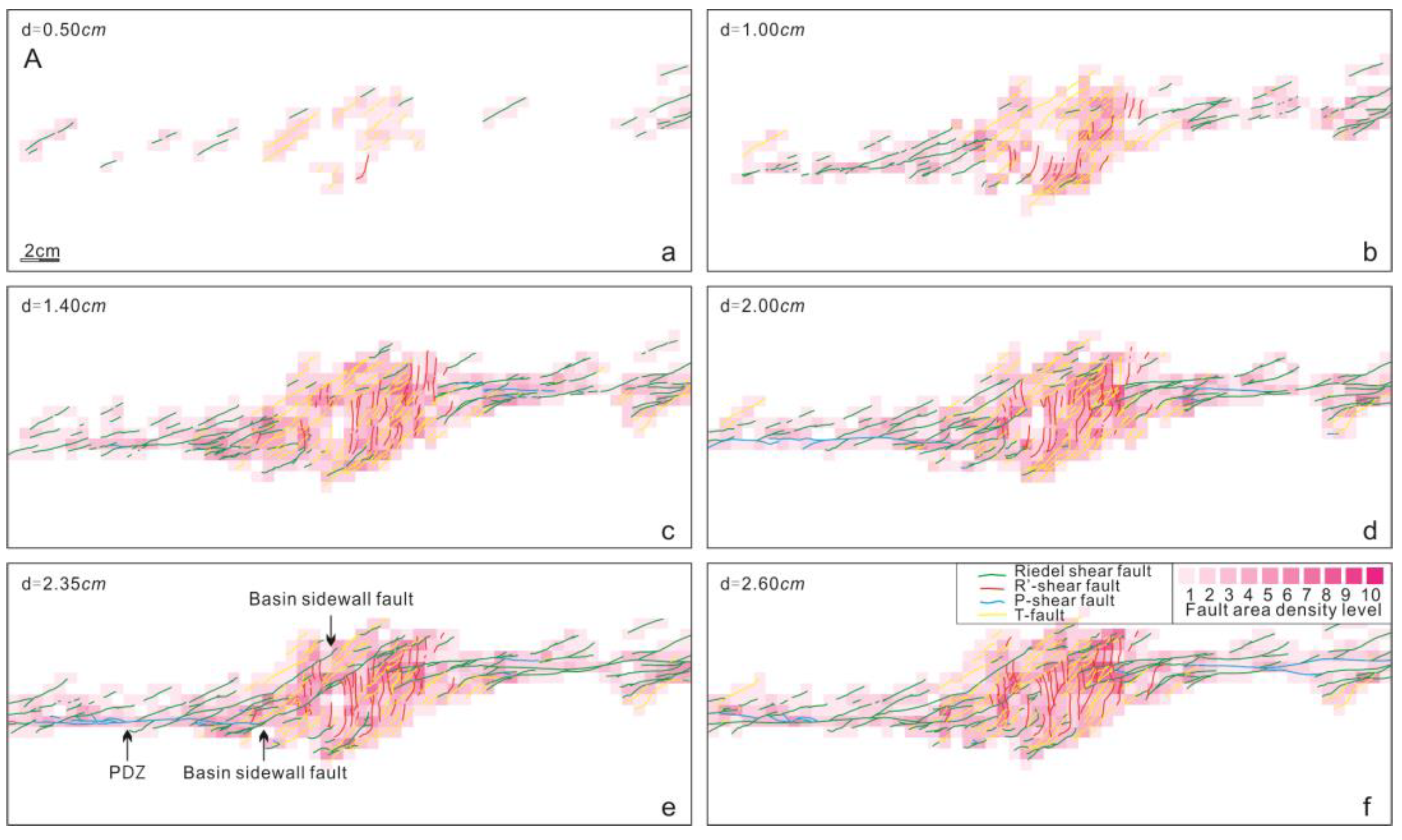
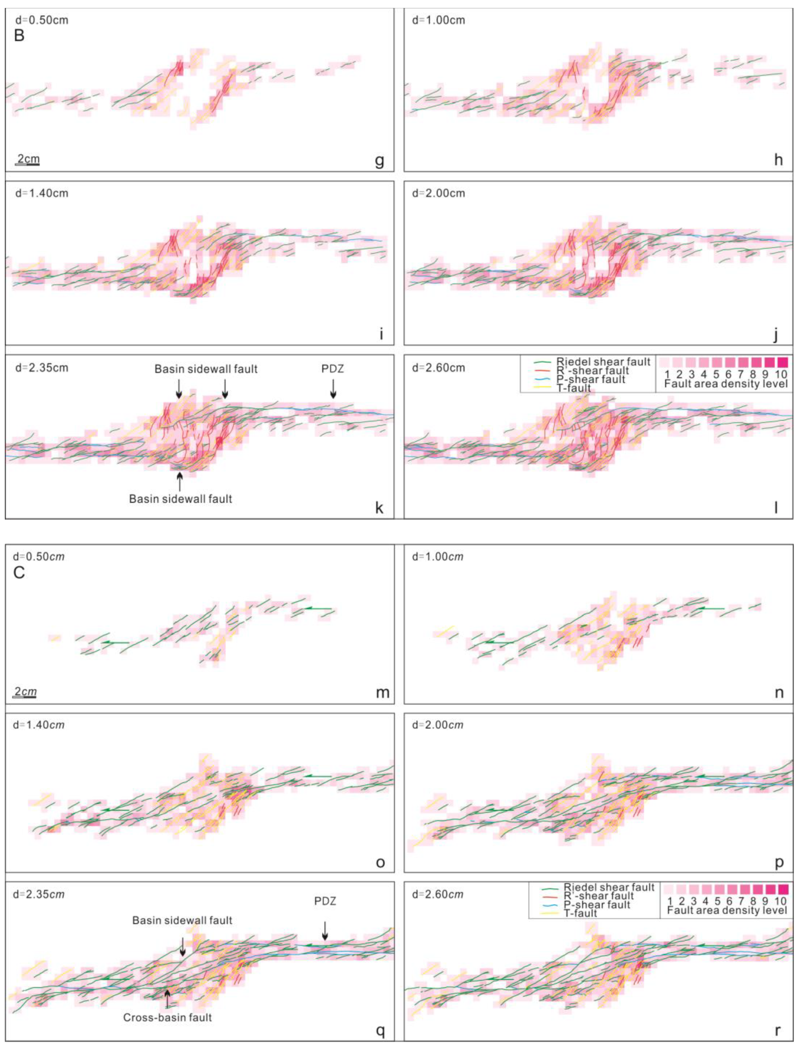
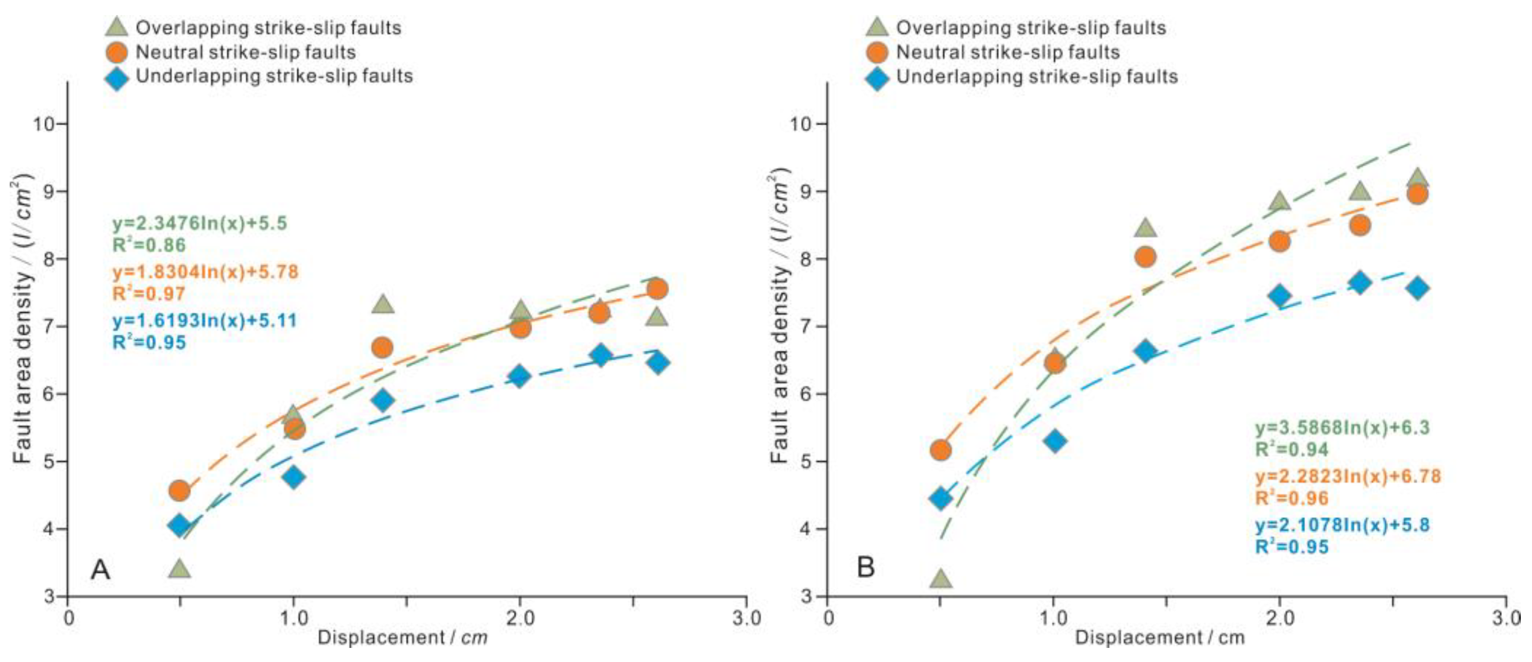
3.2. Characteristics of Fault Area Density

The two strike–slip faults interact at their ends to form the so-called linking (extensional step) or underlapping damage zone [35], in which subordinate faults and/or fractures are densely developed. Similarly, in the present experiment, the fault number and fault area density were higher in the PAB (a type of damage zone) than in the PDZ (Figure 4 and Figure 5). The average fault area density in the PAB gradually increased with an increase in the overlapping degree of two strike–slip faults (i.e., from the underlapping strike–slip fault to the overlapping strike–slip fault (Figure 5B)).
The fault area density gradually increased with an increase in fault displacement (Figure 4a–c). Faults covered the whole PAB during the late stages of all experiments but were concentrated at the edges of the PAB during the early–middle stage (Figure 4e,f,k,l,q,r). The same phenomenon was observed in previous sandbox experiments [8]. The fault area density was maximized at the intersection of the PAB and PDZ. Moreover, the fault area density migrated during the experiments, primarily during the early–middle stage. Migration then stopped during the middle–late stage.

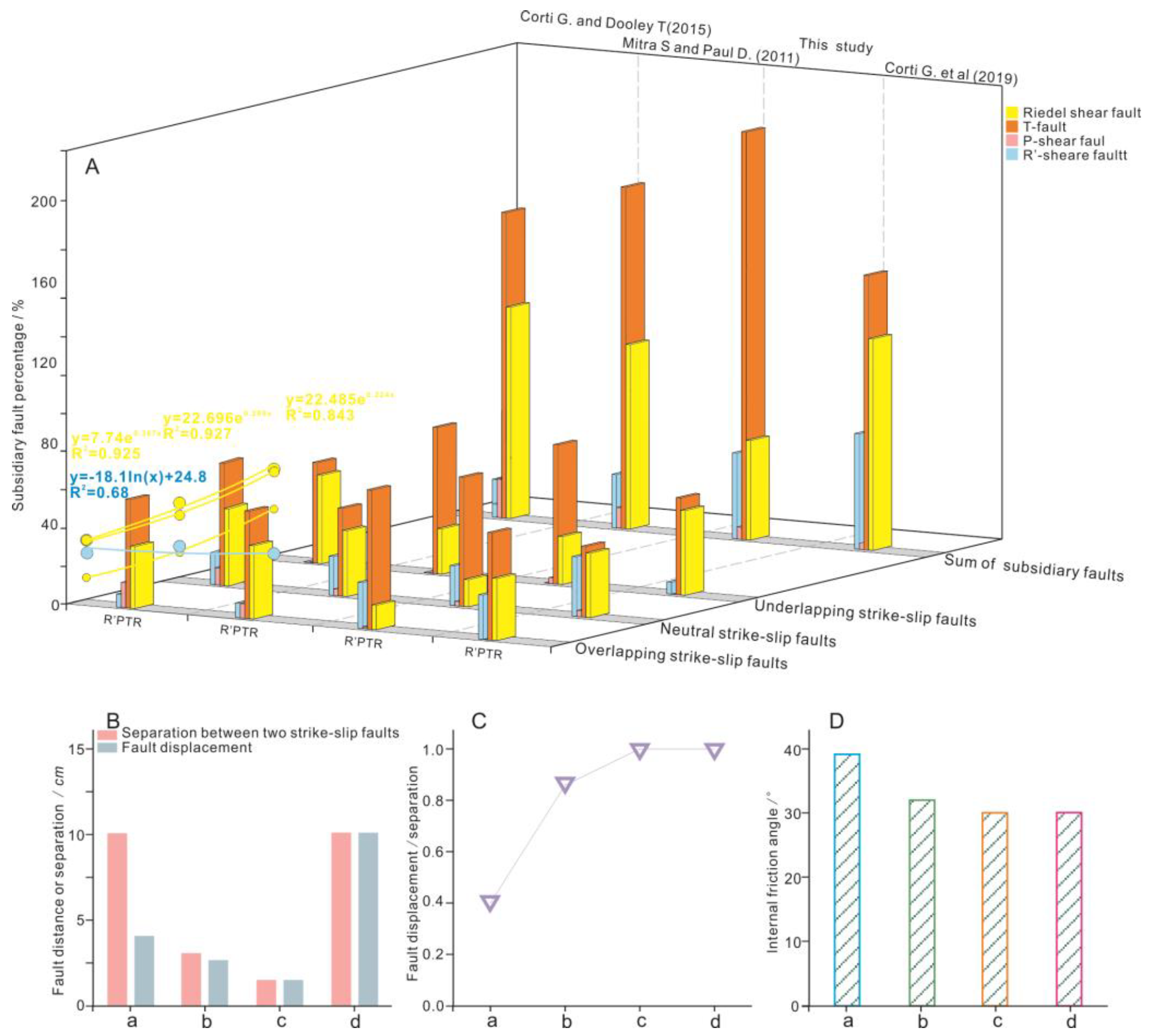
3.3. Characteristics of Subsidiary Faults

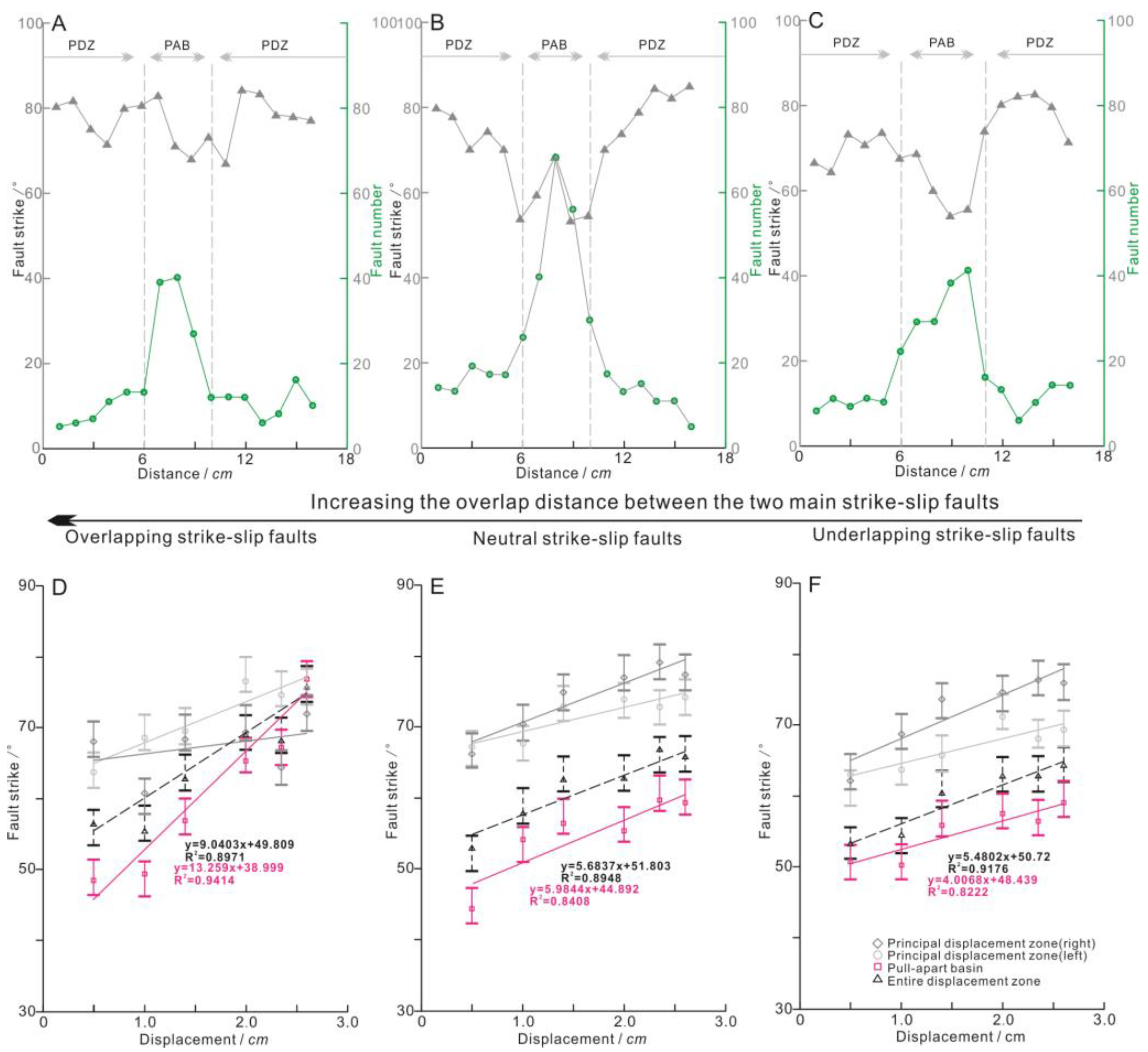
3.3.1. Number of Subsidiary Faults

The number of secondary faults was counted based on the property of the subsidiary fault. For these three experiments (Figure 6), the total number of subsidiary faults increased from the underlapping overlapping strike–slip faults. In the same experiments, the total number of subsidiary faults mirrored the fault area density (Figure 5), being significantly larger in the PAB than in the PDZ. The subsidiary faults with different properties presented different counts in the PAB; T-faults outnumbered the other fault types by at least two orders of magnitude. Furthermore, the number of the most unstable faults (the R′-shear faults) decreased from the overlapping to the underlapping strike–slip faults; however, Riedel shear faults were relatively stable in all PDZs.
The fault number development of the three bend types of strike–slip faults demonstrated two distinct patterns. First, the number of neutral and underlapping strike–slip faults gradually increased with fault displacement (Figure 6D–H). Second, the change in fault number traced an arc-like shape (Figure 6A–C) with a maximum in the middle–late stage of the experiments. Combining these results with the fault evolution, the number of subsidiary faults decreased during the late evolution stage, primarily because small faults coalesced into large faults. Therefore, the gradual increase in fault displacement most possibly caused the merging of en echelon faults into a large fault. However, these processes are not simultaneous and may proceed back and forth many times. That is, a fault block between two en echelon faults may re-rupture into many small faults, temporarily increasing the fault number (Figure 6B).

3.3.2. Strike of Subsidiary Faults

In a strike–slip fault, subsidiary faults with different properties exhibit distinct strikes [36]. Fault strike analysis is helpful for identifying the evolution characteristics of these subsidiary faults.
The average strikes of the subsidiary faults in the three experiments were counted at equal intervals along the strike–slip fault (Figure 7A–C). The average strike of the subsidiary faults in the PDZ was almost independent of the bend type of the strike–slip faults and was clearly separated from the average strike of subsidiary faults in the PAB. This change is primarily related to the surging number of T- and R′-shear faults in the PAB (Figure 6B,E,H).
The average strike of the subsidiary faults was counted in different structural units. Along the strike–slip faults of all three bend types, the average fault strike in different structural units and the total average fault strike gradually increased with increasing fault displacement (Figure 7D–F). During the same experimental process, the average strikes in the left and right PDZs were inconsistent, and their gap enlarged as the fault displacement grew. This phenomenon might be primarily explained by differences in basal plate activity. Comparing the average strikes of the subsidiary faults in the three PABs, one observes that the slope of the average strike increased from the overlapping strike–slip fault to the underlapping strike–slip fault.

4. Discussion

This study discussed the effects of strike–slip faults with different bend types on a PAB, including the morphology of the PAB, the subsidiary fault density, and the fault number and proportion. The subsidiary fault features are deduced through an example.

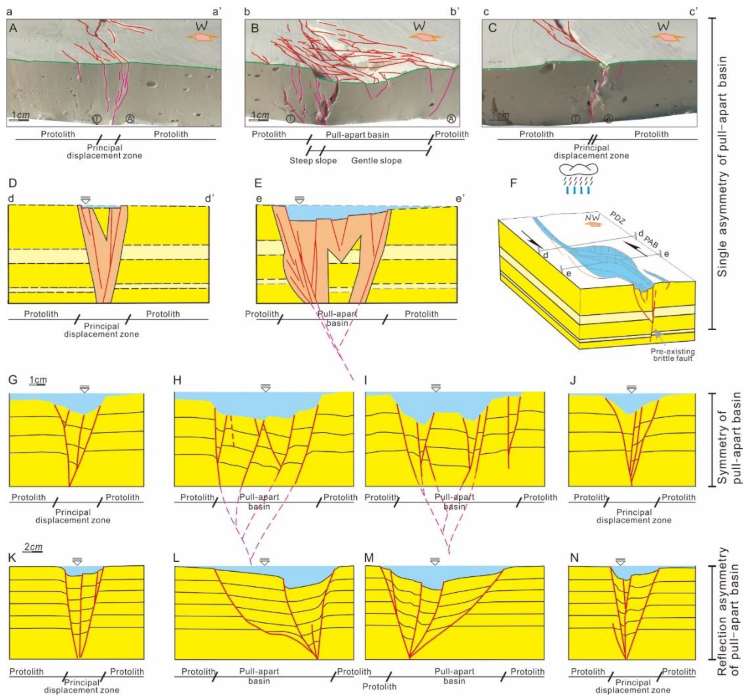
4.1. Morphological Characteristics of the PAB

In the planar view, a PAB associated with strike–slip faults exhibits spindle, rhomboid, or lazy-Z shape morphologies related to subsidiary faults in the PAB [19]. In the present experiments on wet clay material, rhomboids were observed in the PABs with three bend types of strike–slip faults. Obviously, the bend type of the strike–slip faults did not directly affect the shape of the PABs. The present and previous experiments differed in the mechanical properties of their experimental materials [9]. Previous experiments have confirmed that the water content directly affects the mechanical properties of clay [26]. The water content of our clay was obviously higher than in previous experiments.
Typically, flower structures are observed in PDZ profiles, and double fault depressions or half-grabens can be observed in PABs [37,38]. The double fault depression architecture is affected by the thickness of the experimental material and/or the amount of fault displacement [14,19]; similar flower structures often fail to form in the deep layer (Figure 8H,I). A half-graben commonly develops in PABs [17,39] and appears either as a radiating half-graben with two subsidence centers (Figure 8L,M) or as a single asymmetric half-graben (Figure 8B,E). In this study, a single asymmetry controlled by the basin sidewall fault with a large heave was observed in all three experiments (Figure 3). Basin sidewall faults appeared on the side of the mobile plate. Comparing the results of clays with different water contents, a single asymmetry architecture was most possibly reported in wet clays (Figure 2), although the formed architecture slightly depended on the bend type.

4.2. Density and Number of Subsidiary Faults

Regardless of the bend type of the strike–slip faults, the fault number and fault area density were obviously larger in the PAB than in the PDZ. Although all morphological architectures of the PABs controlled by the three bend types were single asymmetric half-grabens, their fault area densities were notably different. (1) In the early–middle evolutionary stage, the fault–area density was zero in the central part of the PABs (Figure 4). (2) The fault area density was maximized at the intersection of the fixed plate and mobile plate in the PAB, i.e., at the acute angle of the diamond (Figure 4f,l,r). The same phenomenon was reported in previous simulations. (3) In the half-graben, the fault area density was smaller in the steep-slope zone than in the gentle-slope zone (Figure 8B).
Wet clay forms multiple faults more easily than sandstone [21]. In the experimental results of Mitra and Paul [8], the fault evolution and fault area density controlled by the offset type of neutral strike–slip faults were similar to those controlled by the bend type of neutral strike–slip faults in this study. Therefore, the subsidiary faults in the PAB are not predominantly affected by the connection mode (bend or offset) between the primary strike–slip faults. Moreover, whether the bend types were controlled by neutral or underlapping strike–slip faults, a region of zero fault area density formed in the early–middle stage, as observed in previous experiments [37,40,41]. However, this region was filled during the late stage of the present experiment. In addition to the impact of fault displacement, the nature of wet clay should not be ignored. As the slope angle of the half-graben increases, very wet clay can develop faults under the action of its own gravity, thus leading to a full distribution of faults in the PAB. This feature most commonly appears in the slope zone of a half-graben in the extensional regime. In PABs, the points of high-fault area density are relatively fixed. The stress concentration at the acute angles of rhomboid PABs is an important factor.
The subsidiary fault number in a strike–slip fault is closely related to the fault evolution. In the usual scenario, the fault number gradually increases in the early and middle stages and gradually decreases in the late evolutionary stage. This behavior is primarily attributable to early en echelon faults, which gradually interconnect into a larger fault, thus decreasing the total fault number in the late stage (Figure 4) [42,43,44]. Such behavior usually occurs in the main fault that controls the half-graben. The positions of the highest fault area density are the only structural parts that favor lateral fault connections. In cases of similar displacement, the overlapping strike–slip fault is the earliest mature connection mode among the three bend types of strike–slip faults (Figure 6).

4.3. Proportion of Different Subsidiary Faults

In a PAB with pure strike–slip motions, the proportion of different subsidiary faults varies similarly to the subsidiary fault area density and fault number. Regardless of the experimental material and connection type of strike–slip faults, T-faults were most commonly found, followed by Riedel shear faults; R′- and P-shear faults accounted for a small proportion of all faults and were unstable (Figure 9). In three out of the four groups, the proportion of Riedel shear faults gradually decreased from the underlapping strike–slip faults to the overlapping strike–slip faults (Figure 9A). The corresponding R′-shear fault was almost zero in the underlapping strike–slip faults (Figure 6H and Figure 9A). The separations between two strike–slip faults and the internal friction angles differed among the experiments (Figure 9B–D); therefore, these factors do not dominantly control the abovementioned phenomenon. Finite-element elastic models demonstrate that the mean normal stress is the primary tensile component in PABs [45]; the strike–slip component minimally aligns with the PDZ and gradually decreases from the underlapping strike–slip fault to the overlapping strike–slip fault. The seesaw changes observed in the Riedel and R′-shear faults are not understood at this time.

4.4. Strike–Slip Mode Analyzed by Subsidiary Faults

The Pearl River Mouth Basin in the northern South China Sea is cut by NW strike–slip faults that divide the basin groups into independent internal tectonic units, each composed of multiple bend types of strike–slip faults (Figure 10A). The Paleogene strata comprise the Shenhu, Wenchang, Enping, and Zhuhai formations from the bottom to the top [46,47]. Its porosity is between 15 and 35%, its permeability is 500–1500 md, and its burial depth is 3000–4500 m, in general.
The NW strike–slip fault located between Lufeng Sag and Huizhou Sag in the northern Pearl River Mouth Basin [39] was developed as the NW accommodation zone from the late Mesozoic. This fault comprises LUHUI southern and northern branches (Figure 10A–C) and is considered an overlapping strike–slip fault based on the current fault assemblage [48,49], with displacement close to 10 km over 40 Ma in the Paleogene. As per the size ratios of the Riedel shear faults, R′-shear faults, and T-faults in the classification statistics of the abovementioned experiments (Figure 6B,E,H and Figure 9A), the two primary strike–slip faults exhibit bend angles of no more than 90° in two periods, and their possible bend types are underlapping in the Wenchang formation and neutral in the Enping formation (Figure 10E). Exploration confirms that Riedel shear faults in the Wenchang formation exert a considerable blocking effect on hydrocarbon migration, whereas T-faults migrate hydrocarbons [50].

5. Conclusions

The water content of wet clay directly affects the morphological characteristics of a PAB. The PAB developed in very wet clay (water content 68%) presented a rhomboid shape and a single asymmetric half-graben in planar and profile views, respectively. The morphological characteristics of the PAB were almost independent of the bend type of the strike–slip faults.
In the PAB, the overall fault area density was accompanied by an increase in fault displacement. The fault area density in the central part of the PAB was zero during the early–middle evolutionary stages but was filled in the later stage. The subsidiary fault area density was dominantly affected not by the connection mode (bend or offset) between the main strike–slip faults but by the nature of the wet clay, which induced higher fault area density in the gentle-slope zone than in the steep-slope zone of the half-graben. The fault area density was maximized at the stress-concentration points at the acute angles of the rhomboid PAB. However, the fault number initially increased with increasing strike–slip fault displacement and then began decreasing as the small faults coalesced into a large fault. Regardless of the experimental material and the strike–slip fault connection type, T-faults were the most numerous fault types in the PABs, followed by Riedel shear faults. R′- and P-shear faults accounted for a small proportion of all faults and were unstable. The proportion of Riedel shear faults gradually decreased from the underlapping strike–slip faults to the overlapping strike–slip faults, while the proportion of corresponding R′-shear faults increased. The proportion of subsidiary faults was primarily influenced by the stress component. The tensile component was preponderant in the PABs, and the strike–slip component gradually decreased from the underlapping strike–slip fault to the overlapping strike–slip fault.
The abovementioned experimental characteristics were reflected in the proportions of different subsidiary faults in the PAB controlled by strike–slip faults across the Pearl River Mouth Basin. Furthermore, T-faults predominated, and the proportions of R and R′ faults alternately changed. The primary controlling factor is the bend type of the strike–slip faults, which differs in different strata. This understanding assists the interpretation of strike–slip faults and the study of hydrocarbon migration.

Author Contributions

Conceptualization, H.L.; formal analysis, C.L.; investigation, C.P.; resources, H.X. (Hao Xu) and Y.J.; writing—original draft preparation, H.X. (Hongyuan Xu); writing—review and editing, C.P. and C.L.; supervision, W.S.; project administration, G.D.; funding acquisition, H.L. and G.D. All authors have read and agreed to the published version of the manuscript.

Funding

This research was funded by the Natural Science Foundation of Hebei Province, grant number D2019209109 and D2020209003.

Data Availability Statement

No new data were created.

Acknowledgments

We would like to thank Guoqi Song and Zhixin Sun for providing advice on the design of the experiments.

Conflicts of Interest

The authors declare no conflict of interest.

References

  1. Palladino, G.; Rizzo, R.E.; Zvirtes, G.; Grippa, A.; Philipp, R.P.; Healy, D.; Alsop, G.I. Multiple episodes of sand injection leading to accumulation and leakage of hydrocarbons along the San Andreas/San Gregorio fault system, California. Mar. Pet. Geol. 2020, 118, 104431. [Google Scholar] [CrossRef]
  2. Sarewitz, D.R.; Lewis, S.D. The Marinduque intra-arc basin, Philippines: Basin genesis and in situ ophiolite development in a strike-slip setting. Geol. Soc. Am. Bull. 1991, 103, 597–614. [Google Scholar] [CrossRef]
  3. Soumaya, A.; Kadri, A.; Ayed, N.B.; Kim, Y.-S.; Dooley, T.P.; Rajabi, M.; Braham, A. Deformation styles related to intraplate strike-slip fault systems of the Saharan-Tunisian Southern Atlas (North Africa): New kinematic models. J. Struct. Geol. 2020, 140, 104175. [Google Scholar]
  4. Neng, Y.; Li, Y.; Qi, J.; Ma, X.; Zuo, L.; Chen, P. Deformation Styles and Multi-Stage Evolution History of a Large Intraplate Strike-Slip Fault System in a Paleozoic Superimposed Basin: A Case Study From the Tarim Basin, NW China. Front. Earth Sci. 2022, 10, 837354. [Google Scholar] [CrossRef]
  5. Guanghui, W.; Bingshan, M.; Jianfa, H.; Baozhu, G.; Xin, C.; Peng, Y.; Zhou, X. Origin and growth mechanisms of strike-slip faults in the central Tarim cratonic basin, NW China. Pet. Explor. Dev. 2021, 48, 595–607. [Google Scholar]
  6. Du, W.; Chen, Y.; Wang, Z.; Bian, Q.; Guo, Z. Tectonic analysis and petroleum significance of Cenozoic faults in Dongping-Niuzhong area in Altyn slope. Pet. Explor. Dev. 2019, 46, 983–990. [Google Scholar] [CrossRef]
  7. Guang, Z.; Youde, X.; Guosheng, L.; Yongsheng, W.; Chenglong, X. Structural and deformational characteristics of strike-slippings along the middle-southern sector of the tan-lu fault zone. Sci. Geol. Sin. 2006, 41, 226–241+255. [Google Scholar]
  8. Mitra, S.; Paul, D. Structural geometry and evolution of releasing and restraining bends: Insights from laser-scanned experimental models. AAPG Bull. 2011, 95, 1147–1180. [Google Scholar] [CrossRef]
  9. Wu, J.E.; McClay, K.; Whitehouse, P.; Dooley, T. 4D analogue modelling of transtensional pull-apart basins. Mar. Pet. Geol. 2009, 26, 1608–1623. [Google Scholar] [CrossRef]
  10. Yassin, M.A.; Hariri, M.M.; Abdullatif, O.M.; Korvin, G.; Makkawi, M. Evolution history of transtensional pull-apart, oblique rift basin and its implication on hydrocarbon exploration: A case study from Sufyan Sub-basin, Muglad Basin, Sudan. Mar. Pet. Geol. 2017, 79, 282–299. [Google Scholar] [CrossRef]
  11. Nevitt, J.M.; Pollard, D.D.; Warren, J.M. Evaluation of transtension and transpression within contractional fault steps: Comparing kinematic and mechanical models to field data. J. Struct. Geol. 2014, 60, 55–69. [Google Scholar] [CrossRef]
  12. Strijker, G.; Beekman, F.; Bertotti, G.; Luthi, S.M. FEM analysis of deformation localization mechanisms in a 3-D fractured medium under rotating compressive stress orientations. Tectonophysics 2013, 593, 95–110. [Google Scholar] [CrossRef]
  13. Corti, G.; Nencini, R.; Skyttä, P. Modelling the influence of pre-existing brittle fabrics on the development and architecture pull-apart basins. J. Struct. Geol. 2020, 131, 103937. [Google Scholar] [CrossRef]
  14. Dooley, T.P.; Schreurs, G. Analogue modelling of intraplate strike-slip tectonics: A review and new experimental results. Tectonophysics 2012, 574–575, 1–71. [Google Scholar] [CrossRef]
  15. Swanson, M.T. Geometry and kinematics of adhesive wear in brittle strike-slip fault zones. J. Struct. Geol. 2005, 27, 871–887. [Google Scholar] [CrossRef]
  16. Reiter, K.; Kukowski, N.; Ratschbacher, L. The interaction of two indenters in analogue experiments and implications for curved fold-and-thrust belts. Earth Planet. Sci. Lett. 2011, 302, 132–146. [Google Scholar] [CrossRef]
  17. Corti, G.; Dooley, T.P. Lithospheric-scale centrifuge models of pull-apart basins. Tectonophysics 2015, 664, 154–163. [Google Scholar] [CrossRef]
  18. Rahe, B.; Ferrill, D.A.; Morris, A.P. Physical analog modeling of pull-apart basin evolution. Tectonophysics 1998, 285, 21–40. [Google Scholar]
  19. Dooley, T.; Mcclay, K. Analog modeling of pull-apart basins. AAPG Bull. 1997, 81, 1804–1826. [Google Scholar]
  20. Schrank, C.E.; Cruden, A.R. Compaction control of topography and fault network structure along strike-slip faults in sedimentary basins. J. Struct. Geol. 2010, 32, 184–191. [Google Scholar] [CrossRef]
  21. Rose, S.; Mitra, S. Deformation along oblique and lateral ramps in listric normal faults: Insights from experimental models. AAPG Bull. 2009, 93, 431–451. [Google Scholar]
  22. Fossen, H. Structural Geology; Cambridge University: New York, NY, USA, 2010. [Google Scholar]
  23. Atmaoui, N.; Kukowski, N.; Stöckhert, B.; König, D. Initiation and development of pull-apart basins with Riedel shear mechanism: Insights from scaled clay experiments. Int. J. Earth Sci. 2005, 95, 225–238. [Google Scholar] [CrossRef]
  24. Schöpfer, M.P.J.; Steyrer, H.P. Experimental modeling of strike-slip faults and the self-similar behavior. Geol. Soc. Am. Mem. 2001, 193, 21–27. [Google Scholar]
  25. Sims, D. The rheology of clay: A modeling material for geologic structures. Eos Trans. Am. Geophys. Union 1993, 74, 569. [Google Scholar]
  26. Eisenstadt, G.; Sims, D. Evaluating sand and clay models: Do rheological differences matter? J. Struct. Geol. 2005, 27, 1399–1412. [Google Scholar] [CrossRef]
  27. Withjack, M.O.; Henza, A.A.; Schlische, R.W. Three-dimensional fault geometries and interactions within experimental models of multiphase extension. AAPG Bull. 2017, 101, 1767–1789. [Google Scholar] [CrossRef]
  28. Bose, S.; Mitra, S. Analog modeling of divergent and convergent transfer zones in listric normal fault systems. AAPG Bull. 2010, 94, 1425–1452. [Google Scholar] [CrossRef]
  29. Withjack, M.O.; Schlische, R.W. Geometric and experimental models of extensional fault-bend folds. Geol. Soc. Lond. Spec. Publ. 2017, 253, 285–305. [Google Scholar] [CrossRef]
  30. Clifton, A.E.; Schlische, R.W.; Withjack, M.O.; Ackermann, R.V. Influence of rift obliquity on fault-population systematics: Results of experimental clay models. J. Struct. Geol. 2000, 22, 1491–1509. [Google Scholar] [CrossRef]
  31. Henza, A.A.; Withjack, M.O.; Schlische, R.W. Normal-fault development during two phases of non-coaxial extension: An experimental study. J. Struct. Geol. 2010, 32, 1656–1667. [Google Scholar] [CrossRef]
  32. Henza, A.A.; Withjack, M.O.; Schlische, R.W. How do the properties of a pre-existing normal-fault population influence fault development during a subsequent phase of extension? J. Struct. Geol. 2011, 33, 1312–1324. [Google Scholar] [CrossRef]
  33. Withjack, M.O.; Jamison, W.R. Deformation produced by oblique rifting. Tectonophysics 1986, 126, 99–124. [Google Scholar] [CrossRef]
  34. Paul, D.; Mitra, S. Experimental models of transfer zones in rift systems. AAPG Bull. 2013, 97, 759–780. [Google Scholar] [CrossRef]
  35. Kim, Y.-S.; Peacock, D.C.P.; Sanderson, D.J. Fault damage zones. J. Struct. Geol. 2004, 26, 503–517. [Google Scholar] [CrossRef]
  36. Sims, D.; Ferrill, D.A.; Stamatakos, J.A. Role of a ductile décollement in the development of pull-apart basins: Experimental results and natural examples. J. Struct. Geol. 1999, 21, 533–554. [Google Scholar] [CrossRef]
  37. Beidinger, A.; Decker, K. 3D geometry and kinematics of the Lassee flower structure: Implications for segmentation and seismotectonics of the Vienna Basin strike–slip fault, Austria. Tectonophysics 2011, 499, 22–40. [Google Scholar] [CrossRef]
  38. Nkodia, H.M.D.V.; Miyouna, T.; Delvaux, D.; Boudzoumou, F. Flower structures in sandstones of the Paleozoic Inkisi Group (Brazzaville, Republic of Congo): Evidence for two major strike-slip fault systems and geodynamic implications. S. Afr. J. Geol. 2020, 123, 531–550. [Google Scholar] [CrossRef]
  39. Wang, X.; Zhang, X.; Lin, H.; Que, X.; He, Y.; Jia, L.; Xiao, Z.; Li, M. Paleogene geological framework and tectonic evolution of the central anticlinal zone in Lufeng 13 sag, Pearl River Mouth Basin. Pet. Res. 2019, 4, 238–249. [Google Scholar] [CrossRef]
  40. Rupprecht, B.J.; Sachsenhofer, R.F.; Zach, C.; Bechtel, A.; Gratzer, R.; Kucher, F. Oil and gas in the Vienna Basin: Hydrocarbon generation and alteration in a classical hydrocarbon province. Pet. Geosci. 2018, 25, 3–29. [Google Scholar] [CrossRef]
  41. Hinsch, R.; Decker, K.; Wagreich, M. 3-D mapping of segmented active faults in the southern Vienna Basin. Quat. Sci. Rev. 2005, 24, 321–336. [Google Scholar] [CrossRef]
  42. Zeng, L.; Gong, L.; Guan, C.; Zhang, B.; Wang, Q.; Zeng, Q.; Lyu, W. Natural fractures and their contribution to tight gas conglomerate reservoirs: A case study in the northwestern Sichuan Basin, China. J. Pet. Sci. Eng. 2022, 210, 110028. [Google Scholar] [CrossRef]
  43. Fu, X.; Su, X.; Gong, L.; Wang, Q.; Gao, S.; Xie, Z. Control of faults and fractures on shale oil enrichment. Geoenergy Sci. Eng. 2023, 228, 212080. [Google Scholar] [CrossRef]
  44. Gong, L.; Liu, K.; Ju, W. Editorial: Advances in the study of natural fractures in deep and unconventional reservoirs. Front. Earth Sci. 2023, 10, 1096643. [Google Scholar] [CrossRef]
  45. Nabavi, S.T.; Alavi, S.A.; Maerten, F. 2D finite-element elastic models of transtensional pull-apart basins. Comptes Rendus Geosci. 2018, 350, 222–230. [Google Scholar] [CrossRef]
  46. Dong, Y.-x.; Wang, Z.-c.; Zheng, H.-j.; Xu, A.-n. Control of strike-slip faulting on reservoir formation of oil and gas in Nanpu sag. Pet. Explor. Dev. 2008, 35, 424–430. [Google Scholar] [CrossRef]
  47. Gogonenkov, G.N.; Timurziev, A.I. Strike-slip deformations in the West Siberian Basin and their impact on exploration and development of oil and gas reservoirs. Cent. Eur. Geol. 2009, 52, 359–390. [Google Scholar] [CrossRef]
  48. Mu, D.; Peng, G.; Zhu, D.; Li, S.; Suo, Y.; Zhan, H.; Zhao, L. Structure and formation mechanism of the Pearl River Mouth Basin: Insights from multi-phase strike-slip motions in the Yangjiang Sag, SE China. J. Asian Earth Sci. 2022, 226, 105081. [Google Scholar] [CrossRef]
  49. Zhu, H.; Li, S.; Shu, Y.; Yang, X.; Mei, L. Applying seismic geomorphology to delineate switched sequence stratigraphic architecture in lacustrine rift basins: An example from the Pearl River Mouth Basin, northern South China Sea. Mar. Pet. Geol. 2016, 78, 785–796. [Google Scholar] [CrossRef]
  50. Xu, X.; Chen, S.; Wang, F.; Hu, K.; Yu, S.; Wang, X.; Gao, Z.; Liu, X. Structural Features and its impacts on hydrcarbon accumlation of neogeoe in Enping sag, Pear River Mouth basin. Geoscience 2014, 28, 543–550. [Google Scholar]
Figure 1. Experimental model set-up with different bend types of the strike–slip fault. The basal designs in (AC) are similar to those of Dooley and McClay, Dooley and Schreurs, and Corti and Dooley [14,17,19]; (A′C′) are the corresponding profiles of (AC), respectively.
Sustainability 15 14143 g001
Figure 2. Influences of wet clay with different water content on the subsidence depth of a pull−apart basin. The water contents in (AC) with the same fault displacement are 68%, 69%, and 70%, respectively; (D) plots the correspondence between subsidence depth and fault displacement.
Sustainability 15 14143 g002
Figure 3. Structural evolutions of the different bend types of the strike–slip faults. In (AC), evolution was controlled by the overlapping, neutral, and underlapping strike–slip faults, respectively, where d is the fault displacement. Panels (af), (gl), and (mr) show the progressive structural evolutions with increasing fault displacement. The green arrow shows the movement direction of the mobile plate. The rose diagrams with 5° increments show the fault numbers at the different stages of structural evolution.
Sustainability 15 14143 g003aSustainability 15 14143 g003b
Figure 4. Fault interpretation and fault area density statistics of different bend types of the strike–slip fault ((ar), corresponding to Figure 3a–r), where (d) is the fault displacement. The different colored lines represent strike–slip faults with different nature. The purple grid is the range of fault area densities from low (light purple) to high (dark purple) where the Arabic numerals in the legend represent the fault number.
Sustainability 15 14143 g004aSustainability 15 14143 g004b
Figure 5. Statistical plots of fault area densities. The abscissa is the fault displacements given in Figure 4. Plotted are the average fault area densities in (A) the strike–slip fault zone and (B) the PAB as functions of fault displacement.
Sustainability 15 14143 g005
Figure 6. Variational trends of subsidiary fault numbers with different bend types. The ordinate represents the displacements in Figure 3 and Figure 4. The criteria of the structural partitions (PDZ and PAB) are consistent with Figure 3. (AC), (DF), and (GI) correspond to Figure 3A and Figure 4A, Figure 3B and Figure 4B, and Figure 3C and Figure 4C, respectively.
Sustainability 15 14143 g006
Figure 7. Strike statistics of subsidiary faults along the overall strike–slip fault zone in the three bend types of strike–slip faults. (AC) are the average fault strikes counted at 5 mm intervals along the strikes of the overlapping, neutral, and underlapping strike–slip faults during the late evolutionary stage (corresponding to Figure 3f,l,r, respectively). The right coordinate (green line) records the number of faults at that point. (DF) plot the average fault strikes in different structural partitions (PDZ and PAB) as the displacement increases, where the abscissa represents the displacements in Figure 3A and Figure 4A, Figure 3B and Figure 4B, and Figure 3C and Figure 4C, respectively.
Sustainability 15 14143 g007
Figure 8. Characteristics of strike–slip fault assemblages in the profiles. (AF) Strike–slip fault assemblage patterns derived from an overlapping strike–slip fault at the profile positions shown in Figure 2A, (D,E) are interpretations of (A,B), where (E) is a single asymmetric half-graben and (F) is a stereogram of (AC). (GJ) strike–slip fault assemblages controlled by the underlapping strike–slip fault [13], where (H,I) are double-fault depressions. (KN) fault assemblages controlled by the underlapping strike–slip fault [9], where (L,M) are half-grabens with radiation asymmetry.
Sustainability 15 14143 g008
Figure 9. Comparison of key structural elements in the PABs. (A) Proportion of secondary faults in PABs controlled by overlapping, neutral, and underlapping strike–slip faults, where R′, P, T, and R denote R′-, P-, T- and Riedel shear faults, respectively; in particular, the Riedel shear fault percent in the three bend types of strike–slip fault from different experiments is calculated; (B) Ratio comparison of fault displacements to separations in different simulation experiments, where results a, b, c, and d are from Corti et al. [13], this study, Mitra et al. [8], and Corti et al. [17], respectively; (C) Comparison of displacements and separations in different simulation experiments; (D) Comparison of internal friction angles in different simulation experiments.
Sustainability 15 14143 g009
Figure 10. Structural analysis of strike–slip faults in the northern Pearl River Mouth Basin, South China Sea. (A) Location of the strike–slip faults in the northern Pearl River Mouth Basin; (B,C) Division of secondary faults in the Enping and Wenchang formations; (D) distribution statistics of secondary faults in the Enping and Wenchang formations; (E) Evolution modes of the strike–slip faults from the Enping period to the Wenchang period. Notably, the above classification of secondary faults is based on Dooley et al. (2012) [14], where the P-shear fault is basically parallel to the principal displacement zone.
Sustainability 15 14143 g010
Table 1. Mechanical parameter statistics of wet clay as the experimental material.
MaterialComposition and Particle Size (mm)Density (g/cm3)Coefficient of Internal FrictionCohesion (Pa)Shear Strength (MPa)
Wet clay [25]Powdered kaolin, nepheline–syenite, and flint ≤0.11.63
(wet)
40
(average)
Wet clay [26]Powdered kaolin, nepheline–syenite, and flint ≤0.11.57–1.82
(wet)
54–130
Wet clay [27]Kaolinite particles (<0.005 mm) and water (40% by weight)1.55–1.600.650
Wet clay [28]1.6–1.65
Stiff clay [8]1.85
Soft water-based clay [8] 1.6–1.65
Wet clay [29]Kaolinite and water (40% by weight)1.60.550
Wet clay [30]Powdered kaolin (≤0.1 mm) and water (40% by weight)1.650.550
Wet clay [31]Kaolinite particles (<0.005 mm) and water (40% by weight)1.55–1.600.650
Wet clay [32]Kaolinite particles (<0.005 mm) and water (40% by weight)1.55–1.600.650
Clay [33]Quartz, kaolinite, small amounts of smectite, illite, orthoclase, and talc 1.610−3
Wet clay [21]1.6–1.65
Stiff clay [34]1.85
1.6–1.65
Disclaimer/Publisher’s Note: The statements, opinions and data contained in all publications are solely those of the individual author(s) and contributor(s) and not of MDPI and/or the editor(s). MDPI and/or the editor(s) disclaim responsibility for any injury to people or property resulting from any ideas, methods, instructions or products referred to in the content.

