Article

The Axial Compression Behavior of Basalt Fiber-Reinforced Recycled Aggregate Concrete-Filled Circular Steel-Tubular Column

1
School of Intelligent Construction, Wuchang University of Technology, Wuhan 430223, China
2
School of Civil Engineering, Henan Polytechnic University, Jiaozuo 454003, China
*
Author to whom correspondence should be addressed.
Sustainability 2023, 15(19), 14351; https://doi.org/10.3390/su151914351
Submission received: 30 August 2023 / Revised: 20 September 2023 / Accepted: 21 September 2023 / Published: 28 September 2023

Abstract

:
Recycled aggregate concrete (RAC) technology has received a lot of attention as a green environmental protection technology. However, the unsatisfactory mechanical behavior of RAC restricts its application in engineering practice. The structure of basalt fiber-recycled aggregate concrete-filled circular steel tubes (C-BFRACFST) can dually improve the mechanical behavior of RAC. To observe the axial compression behavior of the C-BFRACFST column, seven specimens were designed with recycled aggregate replacement ratio (0%, 50%, 100%), basalt fiber (BF) content (0 kg/m3, 2 kg/m3, 4 kg/m3) and length–diameter (L/D, 5, 8, 11) as variable parameters for axial compression tests. The failure mode, load–displacement/strain curve, axial compression deformation, ultimate bearing capacity, energy dissipation, and ductility of specimens have been analyzed. The derived constitutive relation of core basalt fiber-reinforced recycled aggregate concrete (BFRAC) constrained by the circular steel tube and the 3D finite element model of C-BFRACFST column have been established to simulate the whole process of compression. It is observed that instability or shear failure occurs in specimens under axial compression load. When the recycled aggregate replacement ratio was increased from 50% to 100%, the change in the energy-dissipation capacity of the specimens was not significant but the ultimate bearing capacity and displacement ductility coefficient decreased by 3.45% and 8.91%, respectively. When the BF content was increased from 2 kg/m3 to 4kg/m3, the change in the ultimate bearing capacity of specimens was not significant; the energy-dissipation capacity at the later stage of bearing increased, and the displacement ductility coefficient was noted to increase by 13.34%. When the L/D was increased from 8 to 11, the energy-dissipation capacity of specimens was decreased, and the ultimate bearing capacity and displacement ductility coefficient declined by 1.37% and 43.52%, respectively. The finite element simulation results are in agreement with the test results.

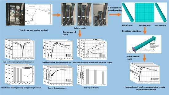
Graphical Abstract

1. Introduction

In recent years, rapid industrialization and urbanization in China have generated about 2 billion tons per year of construction waste. Since construction waste is mostly disposed of in landfills, it not only causes a waste of material resources but also brings great pressure to the ecological environment [1,2,3]. RAC technology produces aggregates from waste concrete after the crushing, screening, cleaning, and sun-drying processes. The resulting aggregates are then used to configure RAC. Therefore, it is necessary to use RAC technology, which is good for improving the utilization of waste materials and slowing down the ecological pressure [4,5] brought about by construction.
However, the mechanical behavior of RAC is unsatisfactory [6,7]. To improve the behavior of RAC, steel tubes and RAC are combined to form a new material structure. The structure can not only have the advantages of both steel and RAC materials but also have high bearing capacity, good ductility, as well as excellent seismic behavior [8,9,10]. Currently, recycled aggregate concrete-filled steel tube (RACFST) members have become a hotspot in studies. Niu et al. [11] investigated the influence of different cross-sections on the axial compression behavior of RACFST, where the results showed that the bearing capacity of specimens with a circular cross-section is superior to a square cross-section for the same cross-section area, steel content, and material strength. Similarly, Guan et al. [12] investigated the axial and eccentric compression behavior of CFRP-reinforced RACFST columns. The results showed that the RACFST columns have a similar deformation mode to ordinary concrete-filled steel tube (CFST) columns while the axial compression bearing capacity of RACFST columns is slightly lower than that of ordinary CFST columns. In another study, Liu et al. [13] studied the bond-slip behavior between recycled aggregate and steel tube under repeated loading, and proposed a formula that can predict the bond strength between recycled concrete and steel tube. Furthermore, in the study by Lyu et al. [14] on the structural bond strength between the steel tube and RAC, results showed that section form and section size are the two main parameters affecting bond strength. The empirical formula for calculating the bond strength between core concrete and steel tube is proposed. Nour et al. [15] established a new model for calculating the bearing capacity of short RACFST columns. Likewise, Yang et al. [16] investigated the behavior of RACFST members and showed that under the same loading conditions, RACFST members have similar behavior as CFST columns, but the bearing capacity and stiffness are lower than those of CFST column members. Tang et al. [17,18] studied the seismic behavior of RACFST columns and the results showed that the material has ideal seismic behavior. Meanwhile, Xu et al. [19,20] investigated the seismic behavior of RACFST columns as well as discovering that RACFST columns have laudable seismic behavior and the recycled aggregate replacement ratio has a minimal effect on the seismic behavior of RACFST column specimens. In another study, Huang et al. [21] investigated the structural damage of RACFST columns under seismic action where the results revealed that the seismic behavior of RACFST columns decreases as the recycled aggregate replacement ratio increases. To summarize, RACFST members and ordinary CFST members have similar and good mechanical behavior that may be applied in engineering practice.
However, the recycled aggregates used to configure RAC will develop microcracks during the production procedure, which will lower the strength and elastic modulus of RAC [5,22,23]. To address these issues, incorporating a certain type of material is necessary. BF is a new type of high-behavior inorganic fiber, and, with the increasing application of composite materials in various projects, the cost-effective advantages of BF have been highlighted [24,25]. Research shows that BF has good chemical stabilities, thermal stabilities, and mechanical behavior [26]. As such, BF is incorporated to make BFRAC with superior results for mechanical behavior, crack resistance, and deformation behavior. This innovative material has also garnered interest for further research. Li et al. [27] investigated the flexural behavior of unbonded prestressed BFRAC beams; according to this research, adding BF may effectively enhance the bonding force between mortar and recycled aggregate, inhibit crack development, increase the cracking load, and enhance ductility. Meanwhile, Zheng et al. [28] and Xie et al. [29] investigated the effect of BF on the mechanical behavior of RAC. The findings showed that the addition of BF significantly increases the flexural strength and splitting tensile strength of RAC, as well as that the compression strength first increases and then decreases. Similarly, Katkhuda et al. [30] researched the impact of BF and acid treatment on the mechanical behavior where the results showed that adding BF significantly improves the splitting tensile and flexural strengths of RAC. Dong et al. [31] investigated the effect of BF on the mechanical behavior and microstructure of RAC. According to research, the addition of BF can improve the structure of the interfacial transition zone, thereby increasing the strength and ductility of RAC. In summary, the addition of BF may efficiently enhance the mechanical behavior of RAC as well as attenuate the effect of microcracks in recycled aggregates used for RAC.
BFRACFST structures improve the mechanical behavior of RAC through the composite restraint of steel tubing and BF on RAC, thereby improving waste-concrete recycling and further increasing the utilization of construction waste [32,33]. However, most of the research focuses on RACFST structures, with fewer studies on RACFST structures mixed with BF. In this study, seven C-BFRACFST column specimens were fabricated, and axial compression tests were performed. The failure modes of specimens were observed. In addition, the axial compression behavior of specimens was analyzed to provide a reference for further study on BFRACFST structures.

2. Test Overview

2.1. Specimen Design and Production

The materials used for the core RAC of C45 are P·O 42.5 grade cement, natural yellow sand, city tap water, Class II fly ash, polycarboxylate superplasticizer, as well as natural and recycled coarse aggregates. The recycled coarse aggregate was obtained from reinforced concrete beams tested at Henan Polytechnic University through manual crushing, grading and screening, and sun-drying. Also, the original concrete design strength grade was C25. The mix proportion of RAC is displayed in Table 1, where the additional water was that needed after considering the water absorption of recycled coarse aggregate. Meanwhile, the fineness of Class II fly ash was 43 μm and its density was 2.34 g/cm3, and the dosage was taken as 20% of cement. The polycarboxylate superplasticizer dosage was 0.5% of the cementitious material (cement and fly ash). According to the mix proportion, BFRAC was prepared, and the measured slump of the BFRAC mixture was in the range of 130~160 mm. Short-cut BF with an outer diameter of 15 μm, length of 18 mm, and density of 2650 kg/m3 was used. The tensile strength, elastic modulus, and elongation at break for short-cut BF were 4500 MPa, 104 GPa, and 3.1%, respectively. The mechanical property indexes of BFRAC were measured according to the Chinese standard “Test methods of concrete physical and mechanical properties” [34], referring to Table 2. Then, the test was conducted using a Q235 grade seamless steel tube with an outer diameter of 114 mm and thickness of 3.5 mm. According to relevant provisions of the Chinese standard “Metallic materials-Tensile testing-part 1: Method of test at room temperature” [35], the measured yield strength and ultimate strength of the steel tube were 318.76 MPa and 373.27 MPa, respectively, while the yield strain, elastic modulus, and Poisson’s ratio were 1758 με, 181 GPa, and 0.33, respectively.
The design and fabrication of the specimens mainly considered three variation parameters: recycled aggregate replacement ratio (γ), BF content, and L/D. A total of seven axial compression specimens were made. When making a specimen, the geometric center of one end of the steel tube was centered on an end plate of dimensions 150 mm × 150 mm × 10 mm and then welded to seal the bottom. Then, well-mixed concrete was poured from the top while continuously vibrating with a vibrating rod until the concrete was dense. After the shrinkage deformation of concrete was not obvious, cement mortar was prepared to smooth the shrinkage gap. After 7 days, the other end of the steel tube was capped with an end plate with a size of 150 mm × 150 mm × 10 mm, and cured at room temperature. The relevant parameters and measured values of the specimens have been displayed in Table 3.

2.2. Test Device and Loading Method

The maximum loading value of a 5000 kN microcomputer-controlled electro-hydraulic servo pressure testing machine (YAW-5000 type) was used to complete the C-BFRACFST column axial compression test. The diagram of the loading device is displayed in Figure 1a, and the section at specimen 1-1 is displayed in Figure 1b.
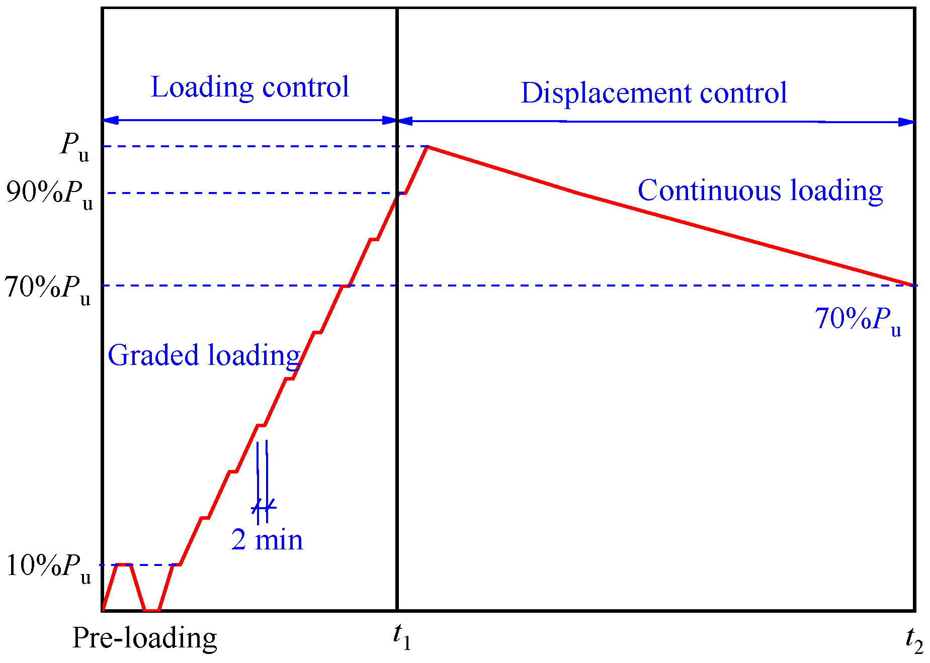
This test uses the loading method of force and displacement combined control. The estimated ultimate load Pu is computed according to Chinese standard “Technical specification for concrete-filled steel tubular structures” [36]. This loading method is referenced in the literature [37,38]. A pre-loading process is performed before the formal loading, holding the load for two minutes, and then unloading. At the beginning of loading, the load is graded by Pu/10 of its ultimate load and held for two minutes each time until it reaches 0.90Pu. At the moment of t1, the load reaches 0.90Pu and is changed from force control to displacement control, where the control displacement grade difference is about 1 mm. At the moment of t2, the load decreases to 70% Pu and the test ends. The monotonic loading system is displayed in Figure 2.

3. Loading Process and Failure Mode of C-BFRACFST Medium-Length Column under Axial Compression

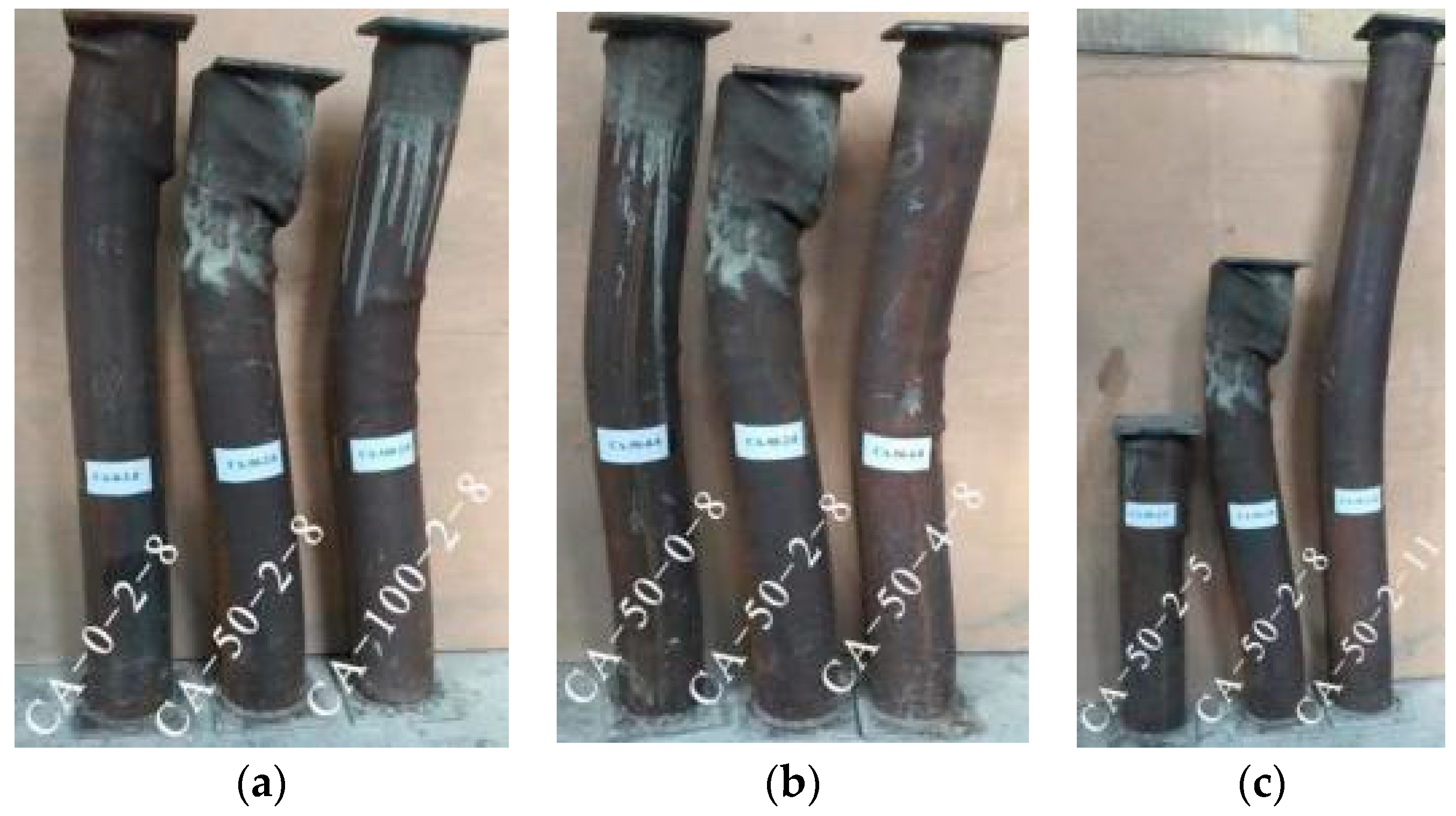
All specimens subjected to axial compression have similar failure processes and macroscopic failure phenomena, which are classified into three loading stages: the elastic stage, elastic-plastic stage, and descending stage. At the beginning of loading, the specimen is in elastic compression; compression deformation increases linearly as the load increases, while the steel tube and core BFRAC each work separately with no mutual extrusion force between their interfaces and there is also little variation in the characteristics of the steel tube surface. As loading continues, the specimen enters the elastic-plastic stage where the rust layer on the surface of the specimen begins to peel off, and at an unfavorable location in the middle or upper part of the specimen a slight local buckling first occurs. At this point, the steel tube in the local area has reached the yield point, wherein the steel tube can still restrain core BFRAC deformation and jointly resist the increasing axial compression load. As the load-increasing speed slows down, the specimen gradually achieves its ultimate bearing capacity and enters the descending stage. Once material locally enters the descending stage, it triggers the specimen to shear or display instability failure. The specimen shows a remarkable decrease in bearing capacity as well as a rapid increase in lateral deformation. When the bearing capacity drops down to 70% Pu, the specimen is considered unsuitable for further bearing, the specimen stops loading, and the test is finished. The failure mode of each specimen is displayed in Figure 3.
In the course of the test, the failure modes of the C-BFRACFST column can be summarized into three categories by observing the test phenomena and final failure modes during the axial compression of specimens. The first type of failure mode is detailed as follows: as loading continued, a slip line divided the core BFRAC in the upper part of the specimen into two parts, accompanied by local buckling occurring on the upper steel tube as well as deflection in the middle, thereby finally forming a shear-failure phenomenon with significant convexity of the core BFRAC in the upper part of the column and further reduction in the bearing capacity, such as in specimens CA-0-2-8, CA-50-2-8, and CA-50-2-5. The second type of failure mode is described as follows: as the loading increases, the first local buckling half-ring appears on the upper part of the specimen. As the loading continues, the first local buckling half-ring expands, and new local buckling appears near the middle of specimen. Finally, an instability-failure phenomenon of the specimen occurs, with a large horizontal deformation caused by severe local buckling in the middle, such as for specimens CA-100-2-8, CA-50-0-8, and CA-50-4-8. The third type of failure mode is as follows: as the loading increases, there is a local buckling half-ring near the upper end plate. As the test progresses, bending deformation of the middle part of the specimen increases and develops towards the other side of the specimen. Finally, there is no local buckling ring in the middle part, but rather an instability-failure phenomenon caused by a large horizontal deformation, such as for specimen CA-50-2-11.
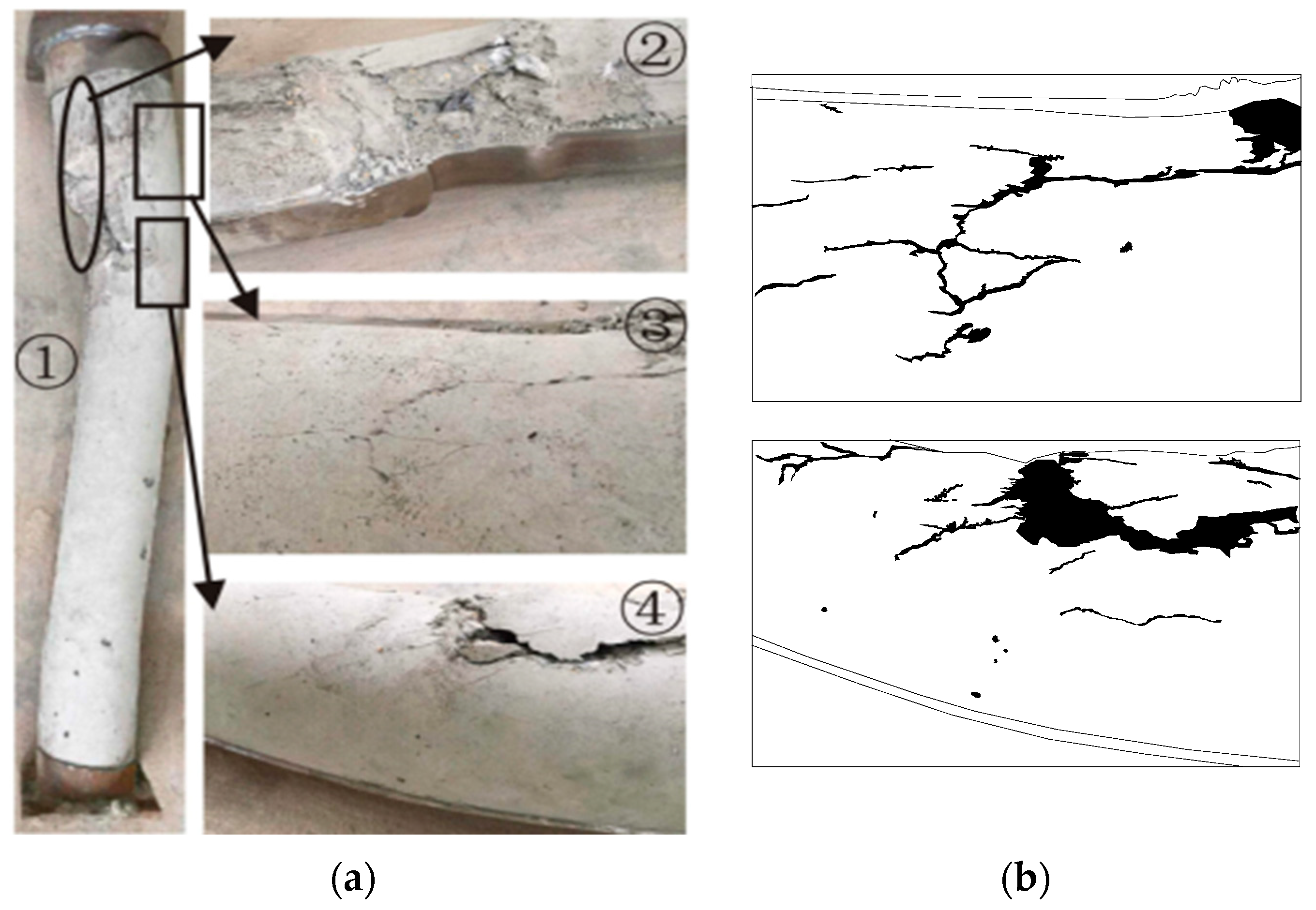
After cutting the outer steel tube of specimen CA-50-2-8 after the test, the failure mode of core BFRAC is displayed in Figure 4a. First, it is observed that the concrete in the upper part undergoes more obvious shear failure while the surface of the core BFRAC in contact with the steel tube does not have severe honeycomb pitting (as shown in Figure 4(a1)). Secondly, dense diagonal microcracks developed on the slip surface after shear failure occurred, and the concrete at the local buckling position is obviously crushed, and the local buckling of outer steel tube is very serious (as shown in Figure 4(a2)). Thirdly, a certain number of diagonal cracks as well as some fine longitudinal cracks are distributed near the shear slip line (as shown in Figure 4(a3)). Finally, the formed concrete was in good contact with the steel tube while no significant horizontal cracks were found on the core BFRAC tensile surface at the maximum deflection (as shown in Figure 4(a4)).

4. Results and Analysis of the Axial Compression Test on C-BFRACFST Medium-Length Column

4.1. Load–Horizontal/Longitudinal Strain Curve

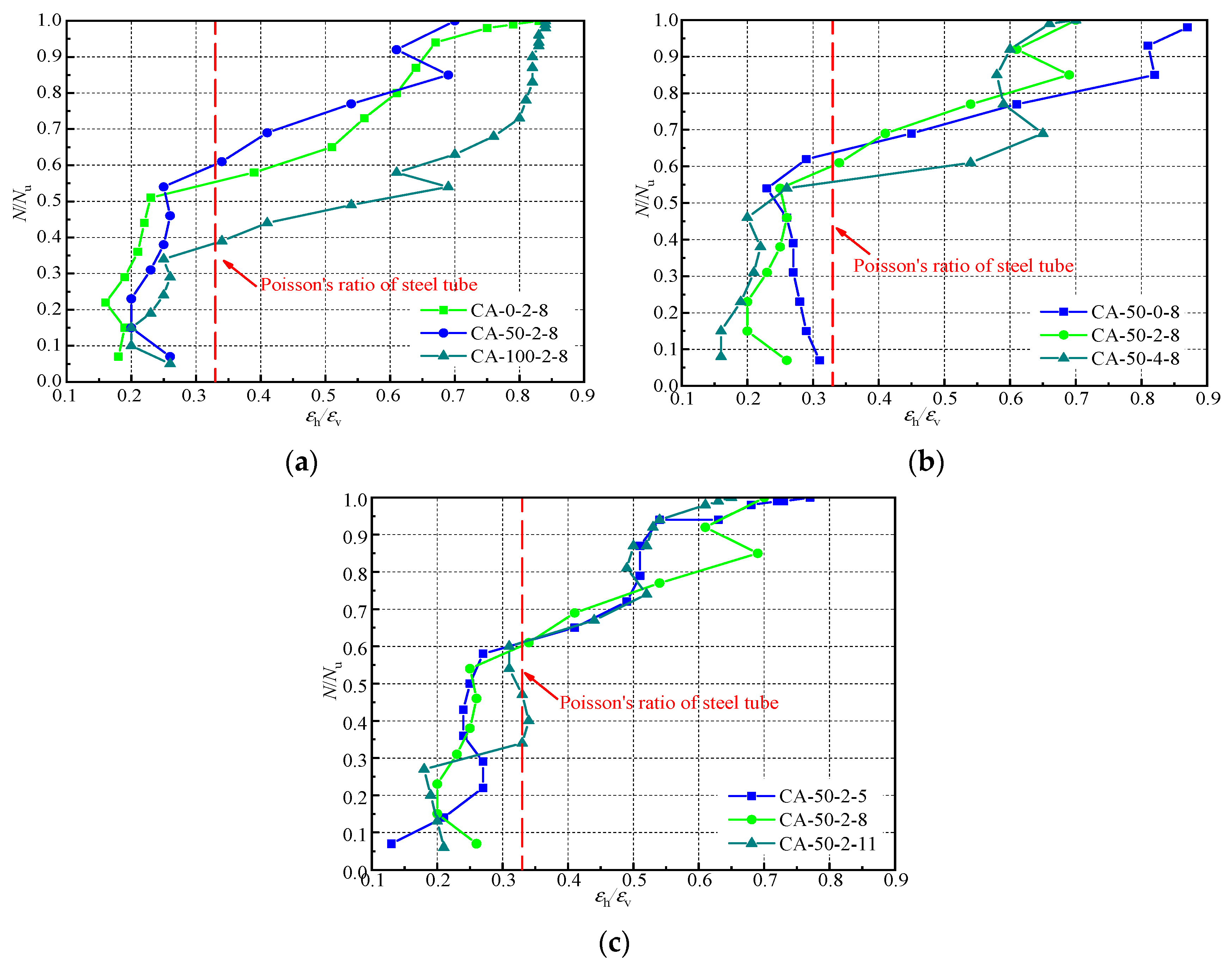
The load–horizontal/longitudinal strain curves for C-BFRACFST columns under a single variable are displayed in Figure 5. A comparative analysis of the graphs in Figure 5 leads to the following conclusions:
The load–horizontal/longitudinal strain curve of a specimen is classified as having three stages. At the initial stage of loading, the load and the horizontal/longitudinal strain of the specimens are roughly linearly developed; this is the elastic stage. With the increase in load, the growth rate of the load is less than the growth rate of the horizontal/longitudinal strain, which is the elastic-plastic stage. After reaching the ultimate load, the load remains almost unchanged, and the horizontal/longitudinal strain of the specimens continues to grow. This stage is the plastic stage;
As indicated in Figure 5a, changing the recycled aggregate replacement ratio does not have any influence on the load–horizontal/longitudinal strain curve at the elastic stage. In the elastic-plastic stage, the load–horizontal/longitudinal strain curves with different recycled aggregate replacement ratios begin to separate, but are still not significant. In the plastic stage, the variation between the three curves varied. It is observed that the recycled aggregate replacement ratio effects the deformation behavior of C-BFRACFST columns mainly in the elastic-plastic stage, as well as the plastic stage;
As indicated in Figure 5b, the curves basically overlap at the beginning of loading, and the slope of the curve CA-50-2-8-h/v (h represents tensile strain, v represents compressive strain) becomes smaller in the elastic-plastic stage following the BF content increasing; in other words, the stiffness gradually decreases. After reaching the ultimate bearing capacity, the horizontal and longitudinal strain curves of specimen CA-50-2-8 and specimen CA-50-4-8 overlap and become flat, indicating that increasing the amount of BF content can increase the C-BFRACFST column resistance to deformation, especially in the plastic stage;
As indicated in Figure 5c, with a constant recycled aggregate replacement ratio as well as BF content, the development of each curve showed some variability at the beginning of loading. The slope of the load–horizontal/longitudinal strain curve of specimen CA-50-2-11 is the smallest in the elastic stage, especially after the specimen enters the elastic-plastic stage, where the strain develops rapidly. This indicates that when the L/D is smaller, as the load increases, the strain grows more slowly, and the ductility is fully developed in the elastic-plastic stage.

4.2. Load–Longitudinal Displacement Curve

Under diverse recycled aggregate replacement ratios, BF content, and L/D ratios, the load–longitudinal displacement curves for C-BFRACFST columns have been displayed in Figure 6. The load–longitudinal displacement curve may be noticed in the figure as being able to be roughly classified as having three stages: the elastic stage, elastic-plastic stage, and descending stage. In the initial stage of loading, the bearing capacity and longitudinal displacement of the specimen develop roughly linearly, and the specimen stiffness remains unchanged. In the elastic-plastic stage, as the load increases, the bearing capacity of specimen increases at a smaller rate than longitudinal displacement, while the specimen stiffness degrades continuously. After reaching the ultimate bearing capacity, the bearing capacity of the specimen begins to decline and longitudinal displacement increases rapidly, which is the descending stage.
As indicated in Figure 6a, the ultimate bearing capacity decreases due to the recycled aggregate replacement ratio increasing. At the end of loading, the bearing capacity of specimens CA-50-2-8 and CA-100-2-8 decreased sharply, while the bearing capacity of specimen CA-0-2-8 decreased slowly. In addition, the later bearing capacity of specimens CA-50-2-8 and CA-100-2-8 were lower than that of specimen CA-0-2-8.
As indicated in Figure 6b, the longitudinal displacements of specimens CA-50-2-8 and CA-50-4-8 were smaller, as the specimens achieved the ultimate bearing capacity. Afterwards, the descending stage of specimen CA-50-4-8 is smoother than that of specimens CA-50-0-8 and CA-50-2-8, which indicates that the increase in BF content improves the specimen ductility.
As indicated in Figure 6c, before achieving the ultimate bearing capacity, the bearing capacity of specimen CA-50-2-11 was less than that of specimens CA-50-2-5 and CA-50-2-8 under the same longitudinal displacement. At the end of loading, the bearing capacity of specimens CA-50-2-5 and CA-50-2-8 rebounded, while that of specimen CA-50-2-11 continued to decrease. The above results show that, with the increase in the L/D, both the preliminary stiffness as well as later bearing capacity of specimens gradually decreased.

4.3. Load Ratio–horizontal Deformation Coefficient Curve

The measured value of the horizontal strain gauge in the middle of the steel tube divided by the measured value of the longitudinal strain gauge is defined as the horizontal deformation coefficient, and the ratio of longitudinal load and ultimate bearing capacity is defined as the load ratio. The load ratio–horizontal deformation coefficient curve for the C-BFRACFST column under axial compression load is displayed in Figure 7. It can be shown from the figure that at initial loading, the horizontal deformation coefficient of the specimen develops slowly, basically changing between 0.2 and 0.3. At this time, the horizontal deformation coefficient of core concrete is clearly lower than that of the steel tubes, and C-BFRACFST columns are subjected to the same forces as ordinary CFST. Meanwhile, the steel tube and core BFRAC bear the longitudinal load together, and there is no mutual compression force between the two sides. As the load increases, when the deformation of the specimen reaches the Poisson’s ratio of the steel tube, the horizontal deformation coefficient of the specimen starts to increase with a larger magnitude, that is, the horizontal deformation of the specimen gradually increases, while at the same time the steel tube gradually constrains core BFRAC.

4.4. Analysis of the Effect of the Ultimate Bearing Capacity and Peak Displacement

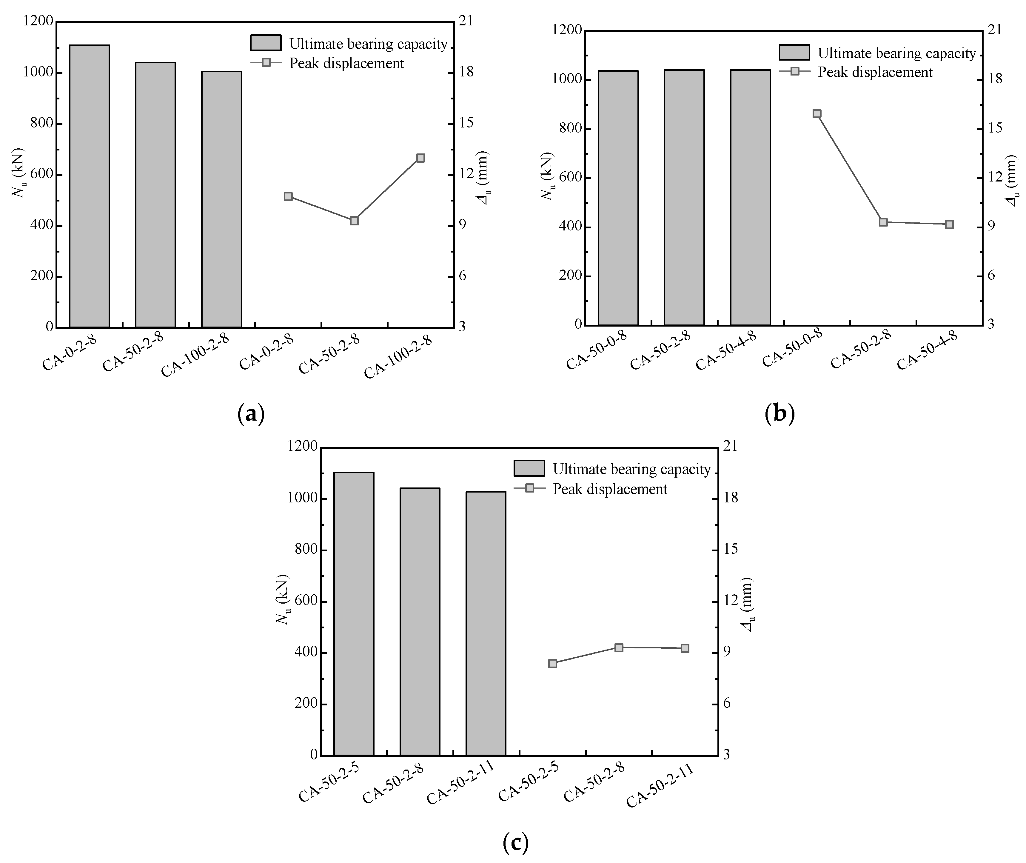
The influence of different recycled aggregate replacement ratios, different BF content, and different L/D ratios on the ultimate bearing capacity and peak displacement have been displayed in Figure 8a–c, respectively.
As indicated in Figure 8a, compared with the specimen with a 50% replacement ratio, the ultimate bearing capacity of specimen with a 0% replacement ratio was raised by 6.53% over that of the specimen with a 50% replacement ratio; the peak displacement corresponding to the ultimate bearing capacity increased by 15.35%, the ultimate bearing capacity of specimen with 100% replacement ratio fell by 3.45%, and the peak displacement corresponding to the ultimate bearing capacity increased by 39.63%. In other words, with an increasing recycled aggregate replacement ratio, the ultimate bearing capacity of the C-BFRACFST column decreases, while the peak displacement first decreases and then increases. The specimen with the smallest peak displacement is CA-50-2-8. This may be because, on the one hand, the recycled aggregate has internal damage after pre-service and crushing; thus, the strength, elastic modulus, and stiffness of the prepared RAC are inferior to ordinary concrete. On the other hand, the recycled aggregate has the disadvantage of having a large porosity. Under an axial compression load, the existence of pores renders the core BFRAC unable to provide effective support to the outer steel tube, causing local buckling of the steel tube in advance, and the axial compression bearing capacity decreases with an increasing recycled aggregate replacement ratio. At a 50% replacement ratio, BF forms a relatively good gradation with natural coarse aggregate and recycled coarse aggregate, which provides good resistance to deformation, thus leading to the phenomenon that the specimen CA-50-2-8 has the smallest peak displacement although the recycled aggregate replacement ratio has increased. This analysis shows that a certain amount of recycled aggregate replacing natural aggregates under axial compression load can reduce the peak displacement of specimens.
As indicated in Figure 8b, as the BF content increases, the axial compression bearing capacity of the C-BFRACFST column hardly changes, while peak displacement gradually decreases. Taking specimen CA-50-2-8 as the reference, the peak displacement increased by 71.32% when BF content from 2 kg/m3 to 0 kg/m3. Meanwhile, increasing BF content from 2 kg/m3 to 4 kg/m3 decreased peak displacement by 1.40%. That is, the specimens’ peak displacement decreased at a fast rate followed by a slower rate with an increasing BF content, which may be attributed to the fact that the BF effectively prevented the expansion of the original initial microcracks in the cement matrix after these appeared in the core BFRAC, while delaying the appearance of new cracks as well. Therefore, increasing the amount of BF content under an axial compression load can reduce the peak displacement of the specimen.
As indicated in Figure 8c, compared with the specimen L/D of 8, the ultimate bearing capacity of the specimen with an L/D of 5 increased by 5.90% and the peak displacement corresponding to the ultimate bearing capacity decreased by 9.99%. The ultimate bearing capacity of the specimen with an L/D of 11 decreased by 1.37% and the peak displacement corresponding to the ultimate bearing capacity decreased by 0.54%. That is, with the L/D increasing, the ultimate bearing capacity of the C-BFRACFST column falls while the peak displacement exhibits an enlarging trend followed by a falling trend, but the changes in ultimate bearing capacity or peak displacement are within 10%. Under axial compression load, with the L/D increasing, the stability of the C-BFRACFST column is not enough; the confinement effect of the steel tube on the core BFRAC recedes, the local deformation of the steel tube reaches the ultimate deformation, and the core BFRAC in this area is crushed, thus showing that the bearing capacity of a specimen reduces as the L/D increases.

4.5. Energy Dissipation

To study the energy dissipation of the C-BFRACFST column under the axial compression load, the load–longitudinal displacement curve based on normalization was used to calculate the energy-dissipation coefficient. As indicated in Figure 9, based on the load-deformation curve of the whole process of axial loading, the ratio of the area of the curved trapezoid from the origin to the loading point ( S O A i Δ i ) divided by the multiplication of the maximum load before the point and the displacement at the point ( N i × Δ i ) is defined as the axial compression energy-dissipation coefficient of the specimen, as shown in Equation (1). The energy-dissipation coefficient which is used to indicate the intrinsic relationship between energy absorption and energy dissipation in the column itself under axial compression load has the significance of a global variable, as shown by the fact that higher values indicate a greater ability to dissipate energy.
η = S O A i Δ i N i · Δ i 0 < Δ i Δ u S O A i Δ i N u · Δ i Δ u < Δ i Δ max
The whole process curve of the energy-dissipation coefficient and relative peak displacement of a specimen under an axial load obtained by calculation is shown in Figure 10.
As indicated in Figure 10a, when Δ/Δu increases from 0 to 3.6, the energy-dissipation coefficient of each specimen does not differ significantly, indicating that changing the recycled aggregate replacement ratio has a minimal effect on the axial compression energy-dissipation capacity of C-BFRACFST column under axial compression load.
As indicated in Figure 10b, when Δ/Δu ≤ 1.8, the energy-dissipation coefficient decreases with the BF content increasing and with the development of plastic deformation of the specimen. When Δ/Δu > 1.8, the energy-dissipation coefficient of the specimen with a BF content of 4 kg/m3 gradually increases and is larger than that of other specimens, which means that, under the action of an axial compression load, increasing BF content can increase the energy-dissipation capacity of a specimen at a later bearing stage.
As indicated in Figure 10c, the energy-dissipation coefficient of specimen CA-50-2-11 is the smallest when Δ/Δu increases from 0 to 3.6, making explicit that the energy-dissipation capacity of a specimen is poorer when the L/D is larger under axial compression loading.

4.6. Ductility Coefficient

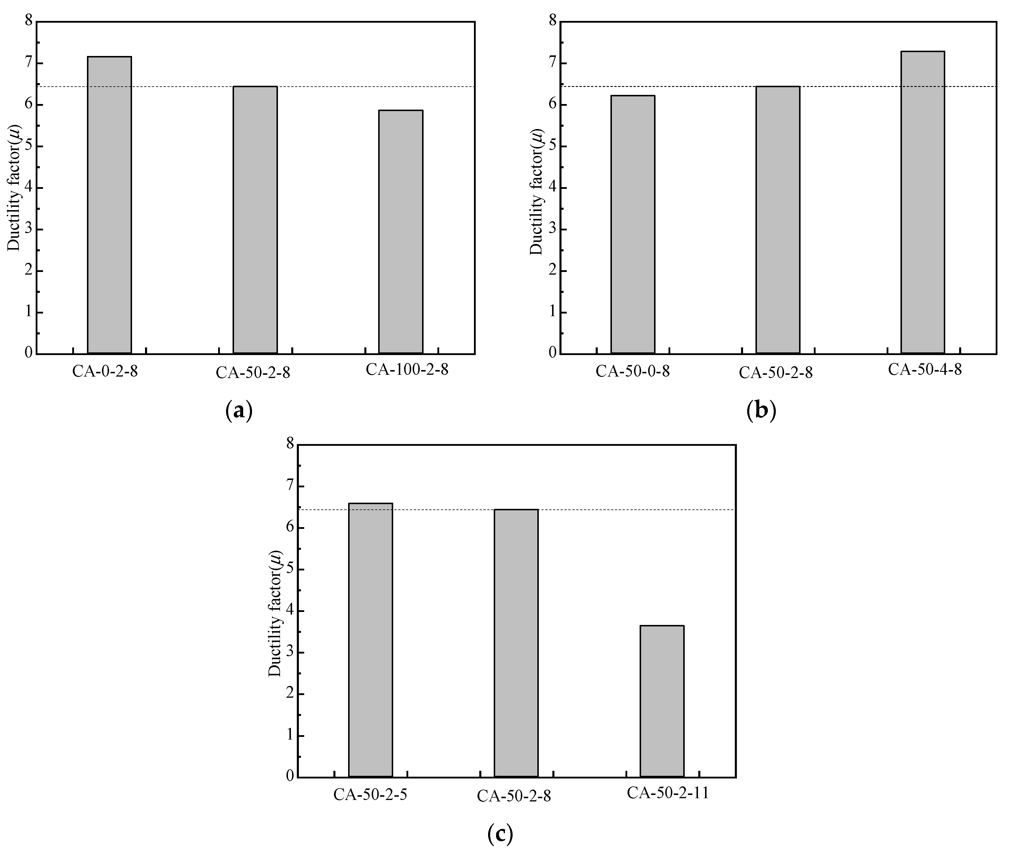
The ductility coefficient is one of the major indices to measure the deformation behavior of a specimen. To study the impacts of various parameters on the ductility of the C-BFRACFST column under axial compression loading, the ductility coefficient (μ) was calculated based on the axial compression load–longitudinal displacement curve of the test, with reference to the Chinese standard “Specification for seismic test of buildings” [39] as shown in Equation (2).
μ = Δ m Δ y
In the formula, Δm is the ultimate displacement of specimen, valued as the corresponding displacement when the load decreases to 85% of the maximum load. Meanwhile, Δy is the yield displacement of specimen, valued as the corresponding displacement when attaining 75% of the maximum load.
The effect of each variation parameter on the ductility coefficient is displayed in Figure 11.
As indicated in Figure 11a, the displacement ductility coefficients of specimens are concentrated in the range of 5.86~7.16 under the single parameter change in recycled aggregate replacement ratio. The displacement ductility coefficient of specimen CA-0-2-8 rose 11.22% over that of specimen CA-50-2-8, while specimen CA-100-2-8 decreased by 8.91%. With increasing recycled aggregate replacement ratio, the displacement ductility coefficient of specimens decreases gradually.
As indicated in Figure 11b, the displacement ductility coefficients of specimens were concentrated in the range of 6.22~7.28 for different BF content, and the displacement ductility coefficient of specimen CA-50-0-8 decreased by 3.38% compared to that of specimen CA-50-2-8, while that of specimen CA-50-4-8 increased by 13.34%. That is, the displacement ductility coefficient of the specimen progressively rises with increasing BF content.
As indicated in Figure 11c, the displacement ductility coefficients of specimens with different L/D are concentrated in the range of 3.64~6.58. Compared with specimen CA-50-2-8, the displacement ductility coefficient of specimen CA-50-2-5 increases by 2.30%, while that of specimen CA-50-2-11 decreases by 43.52%, which is a larger decrease. That is, with increasing L/D, the displacement ductility coefficient of specimens drops progressively.

5. Finite Element Analysis of C-BFRACFST Medium-Length Column

5.1. Constitutive Relation of the Materials

The steel tube constitutive model applies a bilinear model of the uniaxial stress–strain curve. The model uses two straight lines to describe the constitutive relation of elastic–plastic materials, including the elastic stage and plastic-reinforced stage. The elastic modulus in the plastic-reinforced stage can be approximated to 0.01Es (Es is the elastic modulus of the steel tube). Cai et al. [40] established the equivalent constitutive uniaxial compression relation of core concrete which is restricted by a square steel tube. This constitutive model not only has a clear mechanical expression but also can describe the change in ultimate strength and peak strain for core concrete under axial compression as increasing the constraint effect. It has an obvious ultimate stress platform and a smooth and full descending stage. The relevant mathematical calculation equations are displayed in Equations (3)–(6).
f c = f c c x r r 1 + x r
x = ε c ε c c
r = E c E c f c c / ε c c
ε c c = ε c 0 1 + η f c c f c 0 1
where fc and εc are the longitudinal stress and strain of confined concrete, respectively, fcc and εcc are axial compression strength and peak strain of confined concrete, respectively, fc0 and εc0 are axial compression strength and peak strain of unconfined concrete, respectively, η is the peak strain correction coefficient, Ec is elastic modulus of unconfined concrete, and the values of the parameters εcc, η, fsh, fcc, εc0, fc0, Ec are given below.

5.1.1. Determination of the Peak Strain Correction Coefficient η

Han et al. [41] tested 20 CFST stub columns for axial compression, and the results showed that the peak strain correction coefficient η was mainly connected to the width–thickness ratio W of steel tube, the yield strength fy of steel tube, as well as the axial compression strength fc0 of concrete. The calculation equation of η was obtained by regression analysis and is displayed in Equation (7).
η = 52.765 1 W 0.36 f y f c 0 2.0531

5.1.2. Determination of Effective Horizontal Compression Stress of Steel Tubes

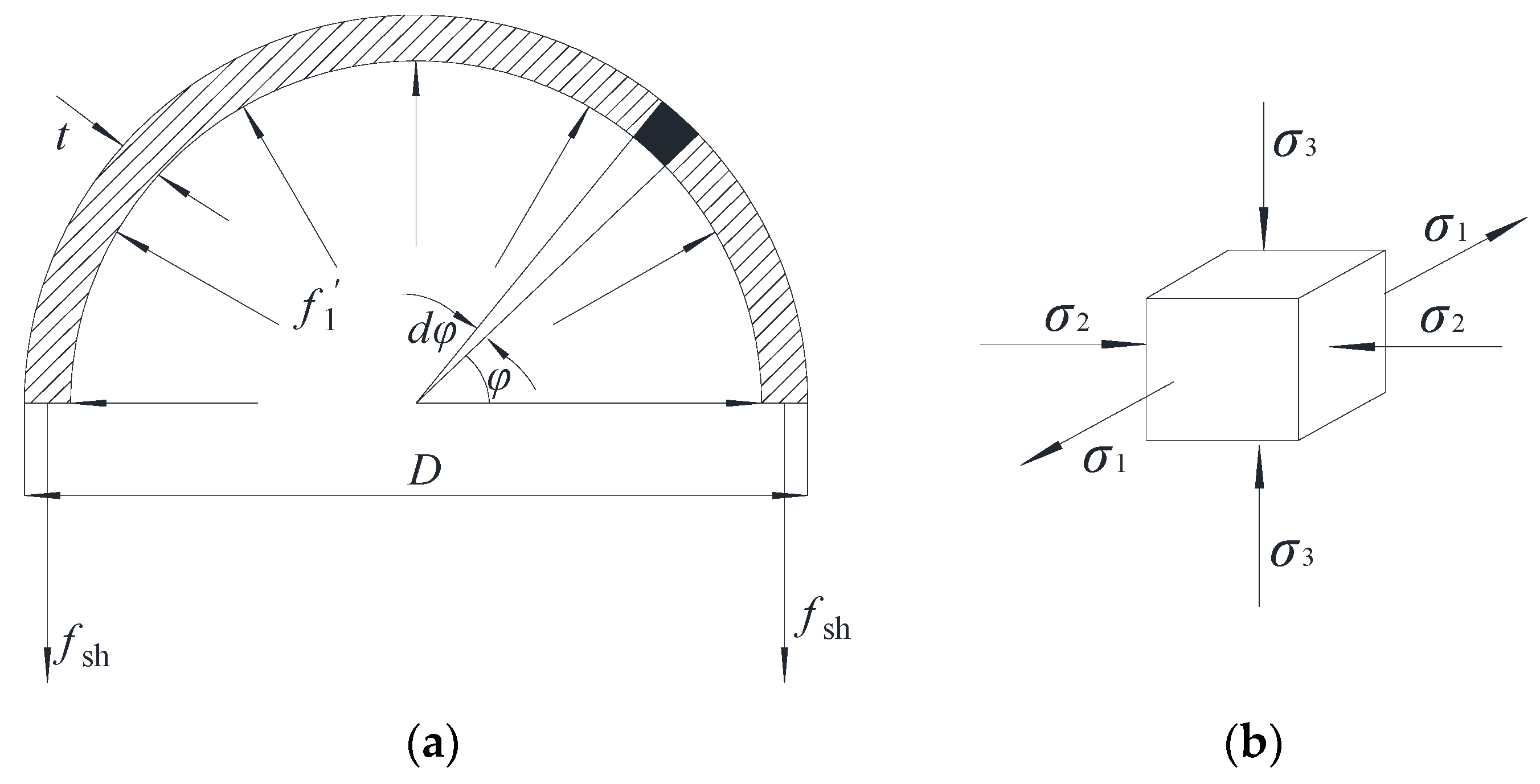
Cai et al. [40] provided a technique for calculating a square steel tube’s horizontal effective compression stress. Based on this, a technique for calculating a circular steel tube’s horizontal effective compression stress is derived in this study. In the calculation, it is assumed that the circular steel tube’s constraint function on the core concrete is uniformly distributed along the circumferential direction of the tube wall. The axial unit length of the circular steel tube is selected as the object for stress analysis, and the selected object is cut along the longitudinal direction which is displayed in Figure 12. Accordingly, Equations (8) and (9) are derived, and f1 shown in Equation (10) is calculated from Equation (9).
F y = 0
2 f s h t × 1 = 0 π f 1 D 2 t 2 d φ sin φ × 1
f 1 = 2 f s h t D 2 t
where f1 is the horizontal compression stress of the circular steel tube, i.e., σ2 of the steel unit, fsh is the circumferential tensile stress in the circular steel tube, i.e., σ1 of the steel unit, D is the outer diameter of circular steel tube, t is the thickness of circular steel tube.
The steel tube’s horizontal compression stress must consider the effect of the effective restraint coefficient, which is displayed in Equation (11). Cai et al. [40] showed that for the square section, the restraint of the steel tube is not uniform, and there are effective strongly-constrained areas and weakly-confined areas. The effective constraint coefficient ke1 of the cross-section is the ratio of the area of the effective strongly-constrained area to that of the weakly-constrained area. The steel tube of the circular section has a uniform restraint on the core concrete, so the effective restraint coefficient of the cross-section is ke1 = 1. Considering the restraint of circular steel tubing on the core concrete as a restraint of the circular hoop with zero longitudinal spacing on the concrete, its horizontal effective restraint coefficient is ke2 = 1. If ke1 and ke2 are brought into Equation (11), the value of the effective restraint coefficient of the CFST can be obtained as 1.
k e = k e 1 k e 2
where ke is the effective constraint factor, ke1 is the effective constraint coefficient of the cross section, and ke2 is the horizontal effective constraint coefficient.
Therefore, the effective horizontal compression stress f1 of the steel tube is shown in Equation (12).
f 1 = f 1 k e

5.1.3. Determination of Circumferential Tensile Stress fsh of Circular Steel Tubes

Under the longitudinal load, the steel tube is in the longitudinal compression, horizontal tension plane stress state (σ2 = 0). For the steel unit as shown in Figure 12b, the Von Mises yield criterion is satisfied during the yielding of steel tubes, and the stress strength of a steel tube on the yield surface is displayed in Equation (13).
σ i 2 = f s 1 2 + f s h 2 f s 1 f s h = f y 2
where σi is the stress strength of the steel tube, fs1 is the longitudinal stress of the steel tube.
The study in [42] showed that W is a major factor influencing the failure mode of CFST specimens, and the formula for calculating W is displayed in Equation (14).
W = D t 12 1 μ s 2 k π 2 f y E s
where μs is the Poisson’s ratio of the steel tube, k is the buckling coefficient of steel tube, and takes a value of 4, and Es is the elastic modulus of the steel tube.
When W > 0.85, the specimen presents local buckling failure, while the local yield strength of steel tube fh (fh = fsl) is the value shown in Equation (15).
f h f y = 1.2 W 0.3 W 2 1.0
When W ≤ 0.85, the influence of local buckling of the specimen is not taken into account, and fsh and fs1 are taken as shown in Equations (16) and (17).
f s h = 0.21 f y
f s 1 = 0.89 f y

5.1.4. Determination of the Axial Compression Strength fcc of the Constrained Concrete

The intrinsic relationship of Mander [43] better reflects the restraint mechanism for the core concrete by a steel tube. Therefore, the axial compression strength of concrete reflected by a circular steel tube still uses the Mander expression as shown in Equation (18).
f c c = f c 0 1.254 + 2.254 1 + 7.94 f 1 f c 0 1 2 2 f 1 f c 0

5.1.5. The Values of Peak Strain εc0, Axial Compression Strength fc0 and Elastic Modulus of Unconfined Concrete

The peak strain of unconfined concrete is displayed in Equation (19) [41].
ε c 0 = 1300 + 12.5 f c k
As demonstrated in Equations (20) and (21), the axial compression strength fc0 as well as the elastic modulus of unconfined concrete are calculated using the Chinese standard “Code for Design of Concrete Structures” [44].
f c 0 = f c k = 0.76 f c u
E c = 10 5 / 2.2 + 34.7 / f c u
where fck indicates the standard value of concrete axial compression strength, and fcu indicates the cubic compression strength of concrete.
Regarding the tensile softening behavior of concrete, the constitutive plastic damage model in ABAQUS provides three approaches, and the stress-fracture–energy relationship based on the damage energy criterion of concrete has better convergence. Therefore, this approach was employed to determine the tensile softening behavior of concrete in this study.
Before utilizing the concrete plastic damage model in ABAQUS to simulate core BFRAC, five key parameters in the plastic damage model must be reasonably selected. The values of each parameter used in this model have been displayed in Table 4.

5.2. Establishment of the Finite Element Model

5.2.1. Element Type Selection and Meshing

To ensure high precision, while avoiding illusory shear locking, the eight-node hexahedral linearly reduced integration element (C3D8R) is selected as the element type of core BFRAC. For the outer steel tube and end plate, we selected a four-node quadrilateral linear reduced integral shell element (S4R) with Simpson’s thickness integration rule and thickness integration point of 5. S4R has stable performance and a wide application range. When defining the material property parameters of the ABAQUS finite element, the end plate is made of a rigid material with larger stiffness; the material property is set as an elastic material. The elastic modulus is set to be 1000 times the steel elastic modulus used, and the Poisson ratio has been adjusted at 0.3, so that the upper and lower end plates resist deformation to a large extent and will not have an impact on the overall deformation and stress distribution.
For this study, the location as well as density of steel tube and concrete nodes are determined by setting the number of global seeds. First, the partition tool is applied to cut the core BFRAC geometry into simple regular shapes, and then the meshing technology of the structure is used to divide the mesh of the core BFRAC. To ensure that the node position is consistent with the seed position, free meshing technology is used to partition the steel tube and end plate, and the advancing front algorithm is selected. At the same time, in order to ensure the control of the boundary surface, mapping meshing technology is used before the free meshing. To ensure calculation accuracy and lower calculation cost, through several debugging operations, the mesh density of the steel tube, cover plate, and core BFRRAC was finally determined to be 40 mm. The finite element model of the parts and entities mesh in this study is shown in Figure 13.

5.2.2. Establishment of Contact

The normal pressure can be effectively transferred between the contact-interface units arbitrarily, allowing the steel tube and BFRAC to separate during the loading process; therefore, the normal contact model uses “hard contact”. Meanwhile, the shear stress transmitted parallel to the interface reaches a critical value at the interface between the relative sliding. Therefore, the tangential contact model uses the Coulomb friction model. The interfacial friction coefficient between steel tube and BFRAC is assumed to be 0.6, which can meet the requirement of model convergence.
In this test, the steel tube and loaded end plate are connected by a welding seam; therefore, the “Tie” constraint in the constraint command is directly used to couple the degrees of freedom of all contact points between the inner surface of the end plate and contact interface of steel tube, completely limiting any friction or slip. The synergistic deformation with the BFRAC is considered to be such that the contact between the inner surface of the end plate and BFRAC is also constrained by the Tie constraint.

5.2.3. Boundary Conditions

The boundary conditions at both ends of the specimen are designed according to test conditions under different loadings. In the finite element simulation, to make model boundary conditions consistent with a boundary condition in the actual loading process, the boundary conditions are set by first defining the loading point and the two ends of the supports as reference points. After the reference point and the corresponding outer surface of end plate are coupled to establish a motion constraint between the point and the surface, the load is imposed on the reference point, and the load is transferred to the end plate through the reference point, and then evenly distributed in a region. The boundary conditions of the finite element model for the axial compression specimen of the C-BFRACFST column are shown in Figure 14.
The load control and double control of load and displacement are not easy to converge in a finite element model. The displacement loading is mainly used to measure the descending stage of the load–displacement curve of a specimen in the actual loading process, which is a crucial component influencing the test’s success. For these reasons, the simulations in this study all adopt the loading method of displacement control.

5.3. Finite Element Simulation Analysis

Comparative Analysis of ABAQUS Results

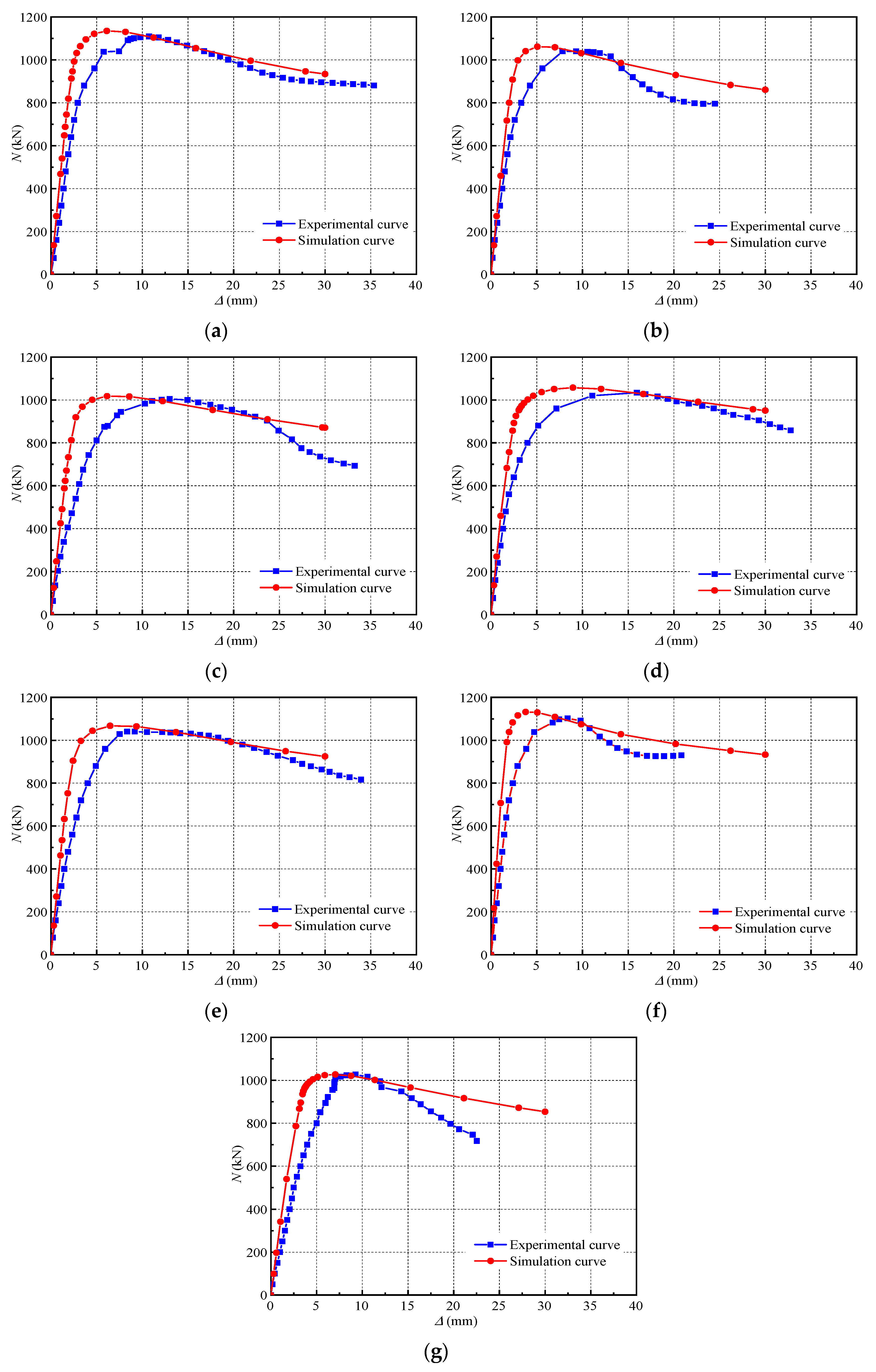
The above material constitutive relation and method of finite element model establishment are adopted to simulate the axial compression of C-BFRACFST, and the finite element simulation load–longitudinal displacement relationship curve is compared with the experimental measured curve, which is displayed in Figure 15.
As indicated in Figure 15, the simulated curve follows the trend of the test curve. The simulated result curve is classified as having two stages: increasing and descending. The descending stage of the curve matches well while the slope of the increasing stage is larger. This is because of the difference between simulation and testing. The finite element (Abaqus 6.14) analysis software assumes steel and concrete units are uniform and isotropic materials and the contacts inside the units are consistent, while the material distribution inside the test specimen is not uniform and is anisotropic. In addition, there are many false displacements during testing, such as the gap between the end plate and concrete, as well as the deformation of the loading device, which may have some effects on test findings.
The finite element calculations Ne of the ultimate bearing capacity of specimens in axial compression as well as measured values of the test Nu have been displayed in Table 5. According to Table 5, the ultimate bearing capacity of the ABAQUS finite element simulations for a C-BFRACFST column under axial compression is higher than the test bearing capacity. However, the discrepancy is less than 8% and the deviation is within the allowable range of the project. In summary, the finite element model created in this study can well reflect the axial compression behavior of a C-BFRACFST column which also verifies the correctness of the ABAQUS finite element model and the feasibility of the analysis method.

6. Conclusions

In this study, axial compression tests and finite element analysis of seven C-BFRACFST column specimens were conducted within the designed parameter variations. The primary conclusions are presented below:
(1)
Under the axial compression load, instability or shear failure occurs in the columns of C-BFRACFST;
(2)
The ultimate bearing capacity of a specimen progressively decreases along with the recycled aggregate replacement ratio or L/D increasing and displays almost no change as the BF content increases. When the recycled aggregate replacement ratio increases from 50% to 100% or the L/D increases from 8 to 11, the ultimate bearing capacity of specimens decreases by 3.45% and 1.37%, respectively;
(3)
Under an axial compression load, changing the recycled aggregate replacement ratio has a minimal impact on the energy-dissipation capacity of specimens, while increasing BF content can increase the specimen energy-dissipation capacity at the later stage of bearing. Meanwhile, the energy-dissipation capacity of specimens is poor when the L/D is relatively large;
(4)
The displacement ductility coefficient of the C-BFRACFST column decreases with the recycled aggregate replacement ratio or L/D increasing, and gradually increases with increasing BF content. When the BF content increases from 2 kg/m3 to 4 kg/m3, the displacement ductility coefficient of specimens increases by 13.34%. However, as the recycled aggregate replacement ratio increases from 50% to 100% or the L/D increases from 8 to 11, the displacement ductility coefficient of specimens decreases by 8.91% and 43.52%, respectively;
(5)
In this study, the constitutive relation of core BFRAC under a constraint of circular steel tubing is derived. On this basis, a finite element model is created, and this model reflects the axial compression behavior of the C-BFRACFST column well.
In this study, the mechanical axial compression properties of C-BFRACST columns were studied experimentally, and a macro model was established for simulation research. Some scholars have studied the fiber distribution and fiber–matrix interface properties, which provides ideas for subsequent research [45,46]. In addition, some scholars have studied the long-term properties and corrosion resistance of concrete members [47,48]. These long-term properties and corrosion resistance have a significant impact on the use and development of concrete components. Therefore, in the future, our research group will also study the long-term properties and corrosion resistance of C-BFRACST columns.

Author Contributions

Conceptualization, J.W.; Methodology, X.Z. and J.W.; Software, X.K.; Validation, C.L.; Formal analysis, C.L.; Investigation, C.L.; Data curation, X.Z.; Writing—original draft, X.Z.; Writing—review & editing, J.W.; Visualization, Y.H.; Supervision, X.K. All authors have read and agreed to the published version of the manuscript.

Funding

This work was supported by the Funds for Establishment Project of Double First-Class Disciplines of Safety and Energy Engineering Department (AQ20230731), the National Natural Science Foundation of China through contracts (52274077, 52279132), the Fundamental Research Funds for the Universities of Henan Province (NSFRF220440) and the Funds for Distinguished Young Scholars of Henan Polytechnic University (J2023-3).

Institutional Review Board Statement

We do not involve human research and do not require ethical approval.

Informed Consent Statement

We do not involve human research.

Data Availability Statement

The data used to support the findings of this study are included within the article.

Conflicts of Interest

The authors declare no conflict of interest.

References

  1. Shi, C.; Li, Y.; Zhang, J.; Li, W.; Chong, L.; Xie, Z. Performance enhancement of recycled concrete aggregate—A review. J. Clean. Prod. 2016, 112, 466–472. [Google Scholar] [CrossRef]
  2. Jin, R.; Li, B.; Zhou, T.; Wanatowski, D.; Piroozfar, P. An empirical study of perceptions towards construction and demolition waste recycling and reuse in China. Resour. Conserv. Recycl. 2017, 126, 86–98. [Google Scholar] [CrossRef]
  3. Wu, G.; Wang, L.; Yang, R.; Hou, W.; Zhang, S.; Guo, X.; Zhao, W. Pollution characteristics and risk assessment of heavy metals in the soil of a construction waste landfill site. Ecol. Inform. 2022, 70, 101700. [Google Scholar] [CrossRef]
  4. Kurda, R.; de Brito, J.; Silvestre, J.D. Combined effect of recycled concrete aggregates and high contents of fly ash on concrete performance. Constr. Build. Mater. 2017, 157, 554–572. [Google Scholar] [CrossRef]
  5. Safiullah, O.; Elhem, G.; George, W. Relationships between recycled concrete aggregates characteristics and recycled aggregates concretes performance. Constr. Build. Mater. 2016, 108, 163–174. [Google Scholar]
  6. Liu, B.; Feng, C.; Deng, H. Shear behavior of three types of recycled aggregate concrete. Constr. Build. Mater. 2019, 217, 557–572. [Google Scholar] [CrossRef]
  7. Zhang, H.; Xiao, J.; Tang, Y.; Duan, Z.; Poon, C.S. Long-term shrinkage and mechanical properties of fully recycled aggregate concrete: Testing and modelling. Cem. Concr. Compos. 2022, 130, 104527. [Google Scholar] [CrossRef]
  8. Van Cao, V. Experimental behaviour of recycled aggregate concrete-filled steel tubes under axial loading. Int. J. Civ. Eng. 2019, 17, 1341–1351. [Google Scholar] [CrossRef]
  9. Fan, C.C.; Huang, R.; Hwang, H.; Chao, S.J. Performance of concrete incorporating fine recycled aggregates from crushed concrete wastes. Constr. Build. Mater. 2016, 112, 708–715. [Google Scholar] [CrossRef]
  10. Chen, J.; Zhang, S.; Wang, Y.; Geng, Y. Axial compressive behavior of recycled concrete filled steel tubular stub columns with the inclusion of crushed brick. Structures 2020, 26, 271–283. [Google Scholar] [CrossRef]
  11. Niu, H.C.; Cao, W.L. Full-scale testing of high-strength RACFST columns subjected to axial compression. Mag. Concr. Res. 2015, 67, 257–270. [Google Scholar] [CrossRef]
  12. Guan, Z.W.; Al-Husainy, A.S.; Al Teneiji, M.; Wang, Q.Y. Concentric and eccentric compression behaviour of recycled aggregate concrete filled steel tube columns strengthened with CFRP. Appl. Compos. Mater. 2022, 29, 983–1005. [Google Scholar] [CrossRef]
  13. Liu, Z.; Lu, Y.; Li, S.; Xiao, L. Enhanced bond-slip behavior between recycled aggregate concrete and steel tubes under repeated loading. Structures 2021, 33, 1263–1282. [Google Scholar] [CrossRef]
  14. Lyu, W.Q.; Han, L.H. Investigation on bond strength between recycled aggregate concrete (RAC) and steel tube in RAC-filled steel tubes. J. Constr. Steel Res. 2019, 155, 438–459. [Google Scholar] [CrossRef]
  15. Nour, A.I.; Güneyisi, E.M. Prediction model on compressive strength of recycled aggregate concrete filled steel tube columns. Compos. Part B 2019, 173, 106938. [Google Scholar] [CrossRef]
  16. Yang, Y.F.; Hou, C. Behaviour and design calculations of recycled aggregate concrete-filled steel tube (RACFST) members. Mag. Concr. Res. 2015, 67, 611–620. [Google Scholar] [CrossRef]
  17. Tang, Y.C.; Li, L.J.; Feng, W.X.; Liu, F.; Liao, B. Seismic performance of recycled aggregate concrete-filled steel tube columns. J. Constr. Steel Res. 2017, 133, 112–124. [Google Scholar] [CrossRef]
  18. Tang, Y.C.; Li, L.J.; Feng, W.X.; Liu, F.; Zhu, M. Study of seismic behavior of recycled aggregate concrete-filled steel tubular columns. J. Constr. Steel Res. 2018, 148, 1–15. [Google Scholar] [CrossRef]
  19. Xu, J.J.; Chen, Z.P.; Xue, J.Y.; Chen, Y.L.; Zhang, J.T. Simulation of seismic behavior of square recycled aggregate concrete-filled steel tubular columns. Constr. Build. Mater. 2017, 149, 553–566. [Google Scholar] [CrossRef]
  20. Xu, J.J.; Chen, Z.P.; Zhao, X.Y.; Demartino, C.; Ozbakkaloglu, T.; Xue, J.Y. Seismic performance of circular recycled aggregate concrete-filled steel tubular columns: FEM modelling and sensitivity analysis. Thin-Walled Struct. 2019, 141, 509–525. [Google Scholar] [CrossRef]
  21. Huang, Y.J.; Xiao, J.Z.; Shen, L.M. Damage assessment for seismic response of recycled concrete filled steel tube columns. Earthq. Eng. Eng. Vib. 2016, 15, 607–616. [Google Scholar] [CrossRef]
  22. Kim, J. Influence of quality of recycled aggregates on the mechanical properties of recycled aggregate concretes: An overview. Constr. Build. Mater. 2022, 328, 127071. [Google Scholar] [CrossRef]
  23. Ulucan, M.; Alyamac, K.E. A holistic assessment of the use of emerging recycled concrete aggregates after a destructive earthquake: Mechanical, economic and environmental. Waste Manag. 2022, 146, 53–65. [Google Scholar] [CrossRef] [PubMed]
  24. Adesina, A. Performance of cementitious composites reinforced with chopped basalt fibres-An overview. Constr. Build. Mater. 2021, 266, 120970. [Google Scholar] [CrossRef]
  25. Jamshaid, H.; Mishra, R. A green material from rock: Basalt fiber-a review. J. Text. Inst. 2016, 107, 923–937. [Google Scholar] [CrossRef]
  26. Dong, J.F.; Wang, Q.Y.; Guan, Z.W.; Chai, H.K. High-temperature behaviour of basalt fibre reinforced concrete made with recycled aggregates from earthquake waste. J. Build. Eng. 2022, 48, 103895. [Google Scholar] [CrossRef]
  27. Li, S.P.; Zhang, Y.B.; Chen, W.J. Bending performance of unbonded prestressed basalt fiber recycled concrete beams. Eng. Struct. 2020, 221, 110937. [Google Scholar] [CrossRef]
  28. Zheng, Y.X.; Zhuo, J.B.; Zhang, P. A review on durability of nano-SiO2 and basalt fiber modified recycled aggregate concrete. Constr. Build. Mater. 2021, 304, 124659. [Google Scholar] [CrossRef]
  29. Xie, J.; Kou, S.C.; Ma, H.; Long, W.J.; Wang, Y.; Ye, T.H. Advances on properties of fiber reinforced recycled aggregate concrete: Experiments and models. Constr. Build. Mater. 2021, 277, 122345. [Google Scholar] [CrossRef]
  30. Katkhuda, H.; Shatarat, N. Improving the performance of recycled concrete aggregate using chopped basalt fibers and acid treatment. Constr. Build. Mater. 2017, 140, 328–335. [Google Scholar] [CrossRef]
  31. Dong, J.F.; Wang, Q.Y.; Guan, Z.W. Material performance of basalt fibre reinforced concrete made with recycled earthquake waste. Constr. Build. Mater. 2017, 130, 241–251. [Google Scholar] [CrossRef]
  32. Zhang, X.; Zhang, S.; Yang, J.; Chen, X.; Zhou, G. Experimental and finite element analyses of eccentric compression of basalt-fiber reinforced recycled aggregate concrete-filled circular steel tubular stub column. Steel Compos. Struct. 2022, 42, 617–631. [Google Scholar]
  33. Zhang, X.; Gao, X.; Wang, X.; Meng, E.; Wang, F. Axial compression performance of basalt-fiber-reinforced recycled-concrete-filled square steel tubular stub column. Adv. Concr. Constr. 2020, 10, 559–571. [Google Scholar]
  34. GB/T50081-2019; Standard for Test Methods of Concrete Physical and Mechanical Properties. China Architecture and Building Press: Beijing, China, 2019. (In Chinese)
  35. GB/T228.1-2021; Metallic Materials-Tensile Testing-Part 1: Method of Test at Room Temperature. Standards Press of China: Beijing, China, 2021. (In Chinese)
  36. CECS 28:2012; Technical Specification for Concrete-Filled Steel Tubular Structures. China Planning Press: Beijing, China, 2012. (In Chinese)
  37. Ke, X.J.; Chen, Z.P.; Xue, J.Y.; Su, Y.S. Experimental study on axial compression bearing capacity of recycled concrete-filled square steel tube short column. Eng. Mech. 2013, 30, 35–41. [Google Scholar]
  38. Yang, Y.L.; Yang, H.; Zhang, S.M. Compressive behavior of T-shaped concrete filled steel tubular columns. Int. J. Steel Struct. 2010, 10, 419–430. [Google Scholar] [CrossRef]
  39. JGJ/T 101-2015; Specification for Seismic Test of Buildings. China Architecture & Building Press: Beijing, China, 2015. (In Chinese)
  40. Cai, J.; Sun, G. Constitutive equation of core concrete under square steel tube restraint. J. South China Univ. Technol. (Nat. Sci. Ed.) 2008, 36, 105–109. (In Chinese) [Google Scholar]
  41. Han, L.H. Concrete Filled Steel Tubular Structures-Theory and Practice, 3rd ed.; Science Press: Beijing, China, 2016; pp. 109–110. (In Chinese) [Google Scholar]
  42. Ge, H.B.; Usami, T. Strength analysis of concrete-filled thin-walled steel box columns. J. Constr. Steel Res. 1994, 30, 259–281. [Google Scholar] [CrossRef]
  43. Mander, J.B.; Priestley, M.J.N.; Park, R. Theoretical stress-strain model for confined concrete. J. Struct. Eng. 1988, 114, 1804–1826. [Google Scholar] [CrossRef]
  44. GB 50010-2010; Code for Design of Concrete Structures. China Architecture & Building Press: Beijing, China, 2010. (In Chinese)
  45. Paknahad, A.; Petre, D.G.; Leeuwenburgh, S.C.; Sluys, L.J. Interfacial characterization of poly (vinyl alcohol) fibers embedded in a calcium phosphate cement matrix: An experimental and numerical investigation. Acta Biomater. 2019, 96, 582–593. [Google Scholar] [CrossRef]
  46. Paknahad, A.; Goudarzi, M.; Kucko, N.W.; Leeuwenburgh, S.C.; Sluys, L.J. Calcium phosphate cement reinforced with poly (vinyl alcohol) fibers: An experimental and numerical failure analysis. Acta Biomater. 2021, 119, 458–471. [Google Scholar] [CrossRef]
  47. Zhao, M.Z.; Wang, Y.Y.; Lehman, D.E.; Geng, Y.; Roeder, C.W. Response and modeling of steel tubes filled with recycled fine and coarse aggregate concretes under long-term loading. J. Struct. Eng. 2021, 147, 04021166. [Google Scholar] [CrossRef]
  48. Meyer, Y.A.; Menezes, I.; Bonatti, R.S.; Bortolozo, A.D.; Osório, W.R. EIS investigation of the corrosion behavior of steel bars embedded into modified concretes with eggshell contents. Metals 2022, 12, 417. [Google Scholar] [CrossRef]
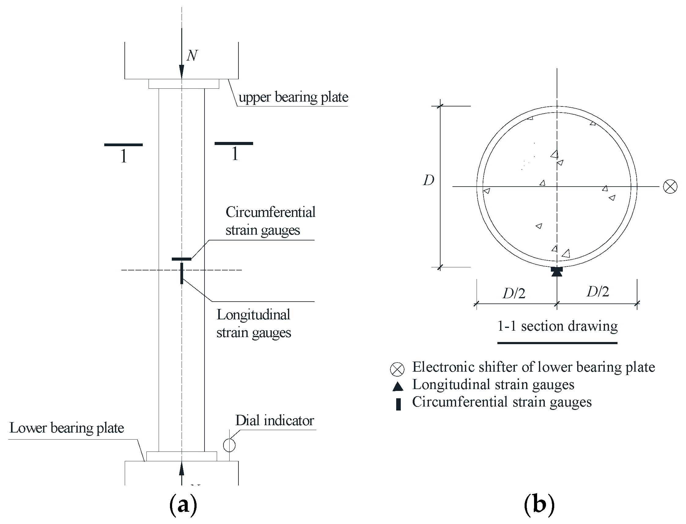
Figure 1. Device for specimen loading. (a) Schematic diagram of the loading. (b) Specimen 1-1 section.
Sustainability 15 14351 g001
Figure 2. Loading system.
Sustainability 15 14351 g002
Figure 3. Failure mode of C-BFRACFST medium-length column. (a) Different recycled aggregate replacement ratio. (b) Different fiber content. (c) Different L/D.
Sustainability 15 14351 g003
Figure 4. The failure modes of BFRAC. (a) Internal BFRAC. (b) Internal BFRAC cracking schematic.
Sustainability 15 14351 g004
Figure 5. Comparison of load–horizontal/longitudinal strain curves. (a) Different recycled aggregate replacement ratio. (b) Different BF content. (c) Different L/D ratio.
Sustainability 15 14351 g005
Figure 6. Comparison of load–longitudinal displacement curves. (a) Different recycled aggregate replacement ratio. (b) Different BF content. (c) Different L/D.
Sustainability 15 14351 g006
Figure 7. Comparison of load ratio–horizontal deformation coefficient curves. (a) Different recycled aggregate replacement ratio. (b) Different BF content. (c) Different L/D.
Sustainability 15 14351 g007
Figure 8. Effect of different variation parameters on Nu and Δu. (a) Different recycled aggregate replacement ratios. (b) Different BF content. (c) Different L/D ratio.
Sustainability 15 14351 g008
Figure 9. Energy-dissipation analysis model.
Sustainability 15 14351 g009
Figure 10. Comparison of energy-dissipation curves of the whole process. (a) Different recycled aggregate replacement ratio. (b) Different BF content. (c) Different L/D ratio.
Sustainability 15 14351 g010
Figure 11. Comparison of ductility coefficient. (a) Different recycled aggregate replacement ratios. (b) Different BF content. (c) Different L/D.
Sustainability 15 14351 g011
Figure 12. Stress analysis of a unit length of circular steel tube. (a) Steel tube. (b) Steel unit.
Sustainability 15 14351 g012
Figure 13. Finite element model meshing. (a) BFRAC mesh. (b) End plate mesh. (c) Steel tube mesh.
Sustainability 15 14351 g013
Figure 14. Boundary conditions of the finite element model of the specimen.
Sustainability 15 14351 g014
Figure 15. Comparison of axial compression test results and simulation results of C-BFRACFST specimens. (a) CA-0-2-8; (b) CA-50-2-8; (c) CA-100-2-8; (d) CA-50-0-8; (e) CA-50-4-8; (f) CA-50-2-5; (g) CA-50-2-11.
Sustainability 15 14351 g015
Table 1. Mix Proportion of RAC.
γ (%)W/BSand Ratio
(%)
Water (kg/m3)Cementitious Material (kg/m3)Coarse Aggregate (kg/m3)Sand (kg/m3)Water Reducer (kg/m3)
Purified WaterAdditional WaterCementFly AshRecycledNatural
00.40312050.0427.185.40.01115.25012.56
500.403120531.2427.185.4557.6557.65012.56
1000.403120562.5427.185.41115.20.05012.56
Table 2. The mechanical property indexes of BFRRC.
γ (%)mBF (kg/m3)fcu (MPa)fc (MPa)Ec (GPa)νc
0252.841.533.50.22
50048.534.929.20.23
250.736.131.40.20
451.938.534.60.18
100246.132.228.30.19
Note: mBF stands for BF content; fcu stands for cubic compression strength value; fc stands for prismatic compression strength value; Ec stands for elastic modulus, whose value is taken as the ratio of stress to corresponding strain at 0.5fc on the BFRAC stress-strain curve; νc stands for Poisson’s ratio.
Table 3. Relative parameters and measured values of specimens under axial compression.
SpecimensL (mm)γ (%)mBF (kg/m3)L/DαξNu (kN)Δu (mm)
CA-0-2-89120280.13511.0381109.3310.74
CA-100-2-8912100280.13511.3381005.3313.0
CA-50-2-891250280.13511.1931041.339.31
CA-50-0-891250080.13511.2341037.6415.95
CA-50-4-891250480.13511.1191041.339.18
CA-50-2-557050250.13511.1931102.878.38
CA-50-2-111254502110.13511.1931027.089.26
Note: L represents the height of the specimen, D represents the outer diameter of the circular steel tube, L/D is the length-to-diameter ratio; α represents the steel content, α = As/Ac, As and Ac represents the cross-sectional area of the steel tube and core concrete, respectively; ξ represents the constraint effect coefficient, ξ = αfy/fc; Nu represents the ultimate load carrying capacity test value of the specimen; Δu is the peak displacement corresponding to the ultimate bearing capacity. The naming method of the specimen, taking CA-50-2-8 as an example: CA represents axial pressure, 50 represents recycled aggregate replacement ratio, 2 represents BF content, 8 represents the length-to-diameter ratio.
Table 4. Key parameters of BFRAC plastic damage model.
Model ParametersDilation AngleEccentricityfb0/fc0KViscosity Parameter
Takes values30°0.11.160.6670.005
Note: fb0/fc0 is the ratio of biaxial to uniaxial compression strength of concrete, and K is the constant stress ratio.
Table 5. Finite element calculation of ultimate bearing capacity of the specimen under axial compression compared with the measured value of the test.
Specimen NumberL (mm)Nu (kN)Ne (kN)Nu/Ne
CA-0-2-89121109.331134.980.977
CA-100-2-89121005.331017.720.988
CA-50-2-89121041.331061.500.981
CA-50-0-89121037.641057.550.981
CA-50-4-89121041.331067.190.976
CA-50-2-55701102.871132.040.974
CA-50-2-1112541027.081027.261.000
Disclaimer/Publisher’s Note: The statements, opinions and data contained in all publications are solely those of the individual author(s) and contributor(s) and not of MDPI and/or the editor(s). MDPI and/or the editor(s) disclaim responsibility for any injury to people or property resulting from any ideas, methods, instructions or products referred to in the content.