Article

A Novel Control Method for Active Power Sharing in Renewable-Energy-Based Micro Distribution Networks

by
Wael J. Abdallah
1,
Khurram Hashmi
2,3,
Muhammad Talib Faiz
4,
Aymen Flah
5,
Sittiporn Channumsin
6,*,
Mohamed A. Mohamed
7,* and
Denis Anatolievich Ustinov
1
1
Department of Electric Power and Electromechanics, St. Petersburg Mining University, 199106 St. Petersburg, Russia
2
Department of Electrical Engineering, University of Engineering and Technology, Lahore 54890, Pakistan
3
School of Electrical and Electronic Engineering, University College Dublin, D04 V1W8 Dublin, Ireland
4
Department of Electronics and Information Engineering, The Hong Kong Polytechnic University, Kowloon, Hong Kong, China
5
Energy Processes Environment and Electrical Systems Unit, National Engineering School of Gabes, University of Gabes, Gabes 6072, Tunisia
6
Space Technology Research Center, Geo-Informatics and Space Technology Development Agency (GISTDA), Chonburi 20230, Thailand
7
Department of Electrical Engineering, Faculty of Engineering, Minia University, Minia 61519, Egypt
*
Authors to whom correspondence should be addressed.
Sustainability 2023, 15(2), 1579; https://doi.org/10.3390/su15021579
Submission received: 9 December 2022 / Revised: 4 January 2023 / Accepted: 7 January 2023 / Published: 13 January 2023

Abstract

:
The microgrid is an emerging trend in modern power systems. Microgrids consist of controllable power sources, storage, and loads. An elaborate control infrastructure is established to regulate and synchronize the interaction of these components. The control scheme is divided into a hierarchy of several layers, where each layer is composed of multi-agents performing their dedicated functions and arriving at a consensus of corrective values. Lateral and horizontal interaction of such multi-agents forms a comprehensive hierarchical control structure that regulates the microgrid operation to achieve a compendium of objectives, including power sharing, voltage, and frequency regulation. The success of a multi-agent-based control scheme is dependent on the health of the communication media that is used to relay measurements and control signals. Delays in the transmission of control signals result in an overall deterioration of the control performance and non-convergence. This paper proposes novel multi-agent moving average estimators to mitigate the effect of latent communication links and establishes a hierarchical control scheme incorporating these average estimators to accurately arrive at system values during communication delays. Mathematical models are established for the complete microgrid system to test the stability of the proposed method against conventional consensus-based methods. Case-wise simulation studies and lab-scale experimental verification further establish the efficacy and superiority of the proposed control scheme in comparison with other conventionally used control methods.

1. Introduction

Renewable and sustainable energy resource (RES)-based distributed energy units (DGUs) have a variable power yield since RESs display a stochastic nature. DGUs, energy storage units (ESU), hybrid electric vehicles (HEV), data acquisition (DAQ) centers, supervisory control strategies, and local and centralized control structures form a microgrid control framework that manages the micro-network [1,2]. A smart micro-distribution network or microgrid (MG) can be described as an autonomous energy transmission and distribution network capable of self-regulation. The prime objective of the MG is to meet the requirements of connected load demands through effectively controlling its generation, energy storage, and transmission resources. It can, therefore, provide a viable solution for renewable energy integration and utilization [3,4,5].
Power converters process variable output from energy resources and regulate voltage and currents through local control loops. For power sharing among various nodes, “primary” controls are employed [6]. Several power-sharing techniques are discussed in the literature, such as communication-based optimized control, P-f, Q-V droop, proportional droop, and so on [6,7,8]. Decentralized droop control schemes are widely utilized in the literature, and in these techniques, proportional reduction has been noted in the frequency and voltage by active and reactive power sharing errors at each distributed node. Several variations have been made in the basic droop techniques so that limitations of conventional droop can be addressed and greater power sharing accuracy can be achieved. However, the limitations of conventional droop control cause a mismatch between the output voltage and frequency and their nominal values. A secondary restorative control layer observes and corrects deviations in frequency and voltage, so that a nominal range of these parameters can be achieved [6,9,10,11,12,13,14,15,16].
Consensus-based control schemes use observers to converge on estimates of values measured at distributed nodes, along with the restoration of voltage and frequency synchronization [1,6,17]. These schemes rely on the transmission of data in the control scheme. These methods can be employed either as a centralized or as a distributed hierarchical control system. Centralized control schemes aim to achieve power sharing in the MG system by utilizing a bidirectional communication structure with a central controller.
The flexibility of the decentralized control techniques for new and innovative control schemes as multi-agent systems is discussed in [6,8,18,19,20,21,22]. Such control methods can combine resources at every node agent to aid in the convergence to the global set point. In such scenarios, the MG control and its operation can be implemented by making an individual power converter an agent within a larger multi-agent-based system. In [8,23,24], MG system objectives, such as restoration of the grid voltage and frequency and power sharing, have been considered as tracker synchronization problems, and all participating system nodes make their efforts for a consensus framework for the corrective values.
Microgrid control and management can be laid out as a multi-level control problem. In this control structure, layer “zero” is responsible for control current and voltage, primary control regulates power-sharing, and secondary control regulates frequency and voltage deviations. Tertiary control performs energy management functions [18,25,26,27]. Secondary controls work on the principle of consensus among all the participating nodes, making restoration of the voltage and frequency a tracker synchronization problem. A consensus-based control structure may be suitable for realizing power-sharing among participating nodes [28]. Reactive power sharing can also be realized at the primary control layer by adopting a distributed control methodology, which also has the ability to regulate the voltage [29,30]. The MG system’s stability is studied in the literature using small-signal modeling with a distributed control scheme to realize the control objectives of the AC grid [17], which highlights substitutes for a secondary centralized control structure and a droop-based primary controller. To regulate different parameters of the AC grid, such as system voltages, active and reactive power regulators have been designed.
The conventional consensus-based controls are heavily reliant upon the efficacy of communication links [7,31]. Fast transmission of measured values, estimated values, and control signals cause early convergence and improve regulation capability, but limitations such as latent communication network and intermittency deteriorate the microgrid’s stability and control performance. However, in order to keep the control simple, and for ease of problem formulation, a fault-free communication network has been adopted in the literature without disrupted or latent communication links [18,25,26,29,32]. The information network characteristics demonstrated in these control approaches are time invarying. In [17,28,33,34,35,36], researchers have considered a communication network with faults so that controller performance can be analyzed in such scenarios.
In networked energy systems, some communication intermittencies in the control and cyber-network layer are probable. Transmission of values and multi-agent consensus-based controls may be affected due to latencies and delay in information exchanges, and the performance of the MG system will deteriorate. To address these challenges, rational and innovative control schemes are required.
In this paper, an improved control technique that addresses latent communication links in a multilevel control scheme for an islanded AC microgrid (MG) network is presented. To realize active power sharing in the microgrid from all distributed connected nodes, a new power sharing technique has been suggested in this study. A degree of resilience to the communication network latencies has been attained by the estimation of average MG parameters at every node. To verify the viability and effectiveness of the proposed control structure, a comprehensive mathematical analysis and detailed simulation study have been conducted, and results are given to validate the proposed method. In order to realize the restoration of the voltage and frequency, a multi-agent-based consensus control layer has been added to the secondary control of the AC grid.
The main contributions and advantages of this study can be summarized as follows:
  • A novel distributed multi-agent moving average estimation technique is proposed that pre-estimates measured values at every node.
  • A hierarchical distributed control structure has been adopted, which incorporates the multi-agent moving average method proposed in this paper, to achieve active power sharing and regulation of the system-wide voltage and frequency values.
  • The viability and effectiveness of the investigated approach is tested for scenarios where the network layer is suffering from communication link latencies.
This paper is arranged as follows: problem formulation, along with particulars of the AC MG model that have been considered in this work, is discussed in Section 2. The proposed hierarchical control scheme is elaborated in Section 3. Section 4 describes the consensus-based observers. Section 5 presents the voltage and frequency restoration controls schemes. The mathematical model derivation for the mentioned control structure is illustrated in Section 6. Section 7 presents the stability analysis of the propsed control scheme in comparison with the existing consensus-based technique, followed by MG system performance assessment with simulation study in Section 8. Section 9 provides the experimental results carried out for verification of the proposed method. Section 10 compares the proposed method to conventional consensus-based methods. Finally, Section 11 concludes the paper.

2. Materials and Methods: Problem Formulation

This section provides the mathematical details required to develop the control problem. The micro-grid network can be imagined as two overlapped systems, namely the power network and the control and communication network. Each individual DGU can be assumed to be a participating node in the multi-agent-based microgrid. To formulate the problem and introduce new control schemes, the component theories are systematically described with the basic concepts of graph theory and a steady-state mathematical model for the power system with the essential mathematical formulation. A brief explanation of communication link latencies has been provided in the following paragraph as a foreword to the work.

2.1. Microgrid Network Discription

A three-phase, three-wire radial distribution network, shown in Figure 1, is used in this work. As can be seen, the power converters at buses 1 through 4 are interfaced with the coupling inductors and LC filters. The varying RL loads have been linked to bus 2 through bus 4. Bus 1 is not feeding the load demand. Bus 5 offers a coupling point that is common with the power grid. The MG system may be managed independently in the “islanded” mode. MG system-rated parameters are presented in Table 1, and system loads are provided in Table 2.
The reactive and active powers being injected from the individual distributed system may be expressed in Equations (1) and (2), respectively. The power network’s simple steady-state model is presented in Equation (3). The YbusMG represents the admittance matrix of the bus for the distribution system.
P i = k = 1 N Y i k V i V k cos ( θ i k + δ k δ i )
Q i = k = 1 N Y i k V i V k sin ( θ i k + δ k δ i )
Y b u s M G V 1 V 2 V 3 V 4 V 5 = I s 1 I s 2 I s 3 I s 4 I s 5
where |Yik| shows admittance connected among i-th and the k-th buses, while |Vi| represents the magnitude of the voltage at the particular i-th inverter, and |Vk| is the magnitude of the voltages at a particular k-th bus; θ i k represents the angle of admittance among the i-th and the k-th buses,   δ k symbolizes the voltage angle at k-th bus, and δ i represents the voltage angle at the i-th bus.

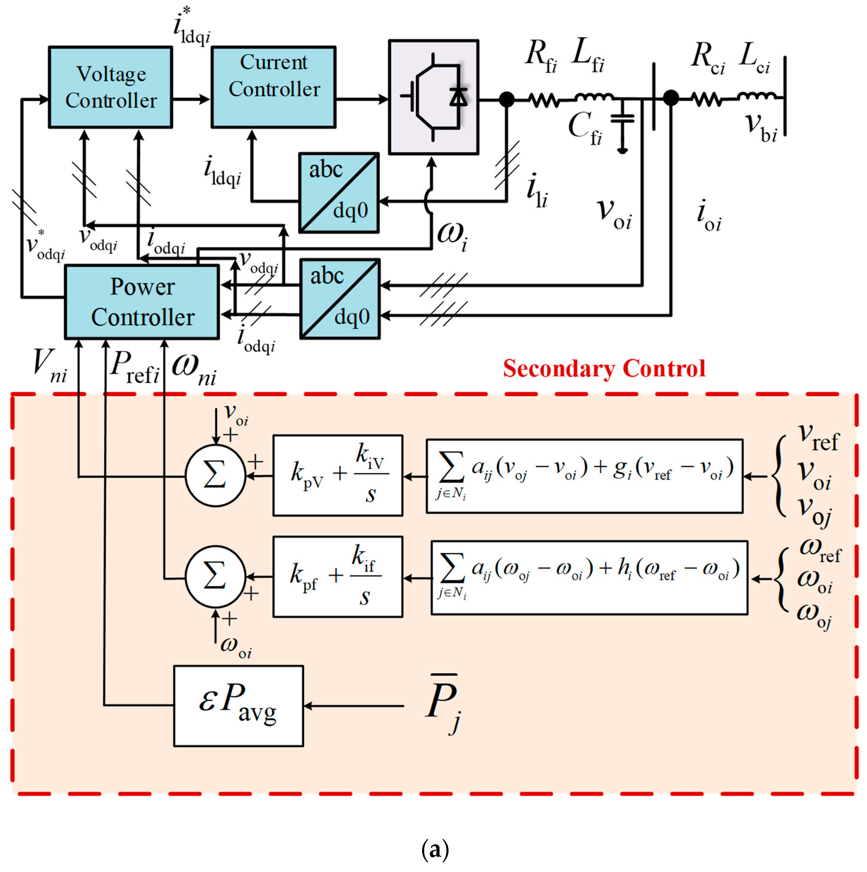
2.2. Hierarchical Controls and Cyber Network

Figure 1 provides a graphical representation of the layered hierarchical control of the complete microgrid system. The zero-level controls are localized at every node and regulate the voltages and currents for each power converter. Above these is the primary control that handles power-sharing based on a modified multi-agent-based technique with the coefficient of the power controller being adopted as (mP*, nQ*). The secondary/tertiary control falls above the primary and secondary layers and contains observers for power, voltage, and frequency values that calculate the above-mentioned constraints based on data from surrounding agent nodes ( U k N ω o i ,   U k N v o i ,   U k N P ε i ) . Corrective terms are generated by the secondary controllers for power supplied to load, voltage, and frequency values (Prefi, ωni, Vni).

2.2.1. Graph Theoretic Formulation

The measured quantities and the corresponding control signals are transmitted though the communication network layer as illustrated in Figure 2a, which can be exhibited as a digraph as Ψ = Φ g , E g , A g , consisting of a non-empty finite set of the N number of agents, located at vertices defined as Φ g = ϕ 1 , ϕ 2 , ϕ 3 , ... , ϕ N . The arcs that join the distributed vertices are represented by E g Φ g × Φ g . The adjacency matrix can be described as A g = a i j R N × N . For a microgrid structure, the agent nodes describe system nodes for the di-graph, and the communication networks that connect them can be shown as arcs [37]. Figure 2a explains the communication among the secondary and primary controls of individual nodes. Correction terms for voltage and frequency V n j ,   ω n j have been produced by the observer to achieve the required references of voltage and frequency v r e f , ω r e f   and neighbor estimates v o j ,   ω o j . In addition, P r e f i calculates the average reference for the injected power based on the average power references ε P a v g , as shown later in the mathematical analysis presented in Section 3.
A stable, time-invariant communication network is considered as shown in Figure 2b. To simplify the estimation process, transmission noises can be neglected. A time-invariant di-graph represents the communication network, that is, A g is considered as a constant for each run of the experiment and simulation. An arc that emanates from the node j and is directed towards the node i can be represented as ϕ j , ϕ i ; the node j collects data from the node i. The weight aij represents the strength of the communication link connecting vi to vj, and a i j > 0 if ϕ j , ϕ i E g , otherwise a i j = 0 . Node i is known as a neighbor of j if the arc ϕ i , ϕ j E g . A set of the neighboring nodes to the i-th node v i   may be represented as N i = ϕ j V g : ϕ i , ϕ j E g . The Laplacian matrix can be defined as, Λ g = ( l i j ) N × N , where l i j = a i j , i j and l i j = j 1 N a i j for i = 1 , , N , such that Λ 1 N = 0 , with 1 N = 1 ,   , 1 T   R N . The in-degree matrix may be represented as D g in = diag   d i in , where d i in = j     N i ( a j i ) , and the out-degree matrix as D g out = diag   d i out , where d i out = i     N i a i j .
A multi-agent observer function has been employed through the control network causing the states of system x to converge over some delay, which can be expressed as Equations (4) and (5).
x ˙ = C ( D g A g ) x = C Λ g x
where
Λ g = D g A g
In addition, Λ g is the Laplacian matrix calculated for the communication structure, which is dependent on the adjacency matrix A g and the degree matrix D g . The system states that are represented by x and x ˙ denote a vector containing values obtained through the algorithm of the consensus. The convergence factor has been denoted by C, and its value is dependent on the parameters of the network [38]. Moreover, the Λ g , D g , and A g matrices utilized for the communication model have been illustrated in Appendix B.1, Appendix B.2 and Appendix B.3, respectively.

2.2.2. Cyber-Network Link Latencies

In this study, a communication system is considered. Due to the presence of network latencies, three participating nodes have been influenced directly (i.e., DGU 1, 3, and 4), as depicted in Figure 3c. The communication links, represented by dotted lines, experience latencies, while the DGUs are regarded as 1 to 4. DGU 4 is dually influenced by the link deterioration. The communication link latencies for the networked control system can be expressed as Equation (6):
x p ( k + 1 ) = A . x p + B . u p y p = C . x p
y p = y c ( k t d )
where the matrices A, B, and C express the state-space matrices of a networked control system in discrete time, x p is system state vector adopted in modeling, and u p and y p represent the input and outputs of the system, respectively [39]. In this study, communication delay has been approximated as the uniform unit delay t d [38]. The value of the time delay has been incrementally varied in the discrete equal steps, so that increasing delay for the different scenarios can be emulated.

3. Distributed Multi-Agent Moving-Average-Based Control

This section outlines the proposed control method for distributed value estimation and active power sharing. An overview of the method is provided in Section 3.1, followed by a detailed elaboration of the proposed estimators in Section 3.2.

3.1. Overview of the Power Estimation Method

A new control technique is devised for power control and presented here. Considering the concepts of finite and infinite impulse response filters (IIR and FIR) [40], distributed multi-agent moving average estimators have been implemented on each DGU and are described in Figure 2a and Figure 3b. All participating DGUs calculate the average system reference on the calculations received from the neighboring agent. The average power estimates are considered as a correction term for the localized droop control by referring to Equation (7), where the frequency is reduced proportionally to obtain active power sharing accordingly. As shown in Figure 3a, Equations (8) and (9) provide the droop controller. In addition, xm1 through xmN represent locally measured values, whereas x1 through xN represent average estimates, and the term z−1 represents a transmission unit delay of one processing cycle.
ω i * = ω i m P i ( P m i P ¯ i )
x i ( k + 1 ) = x m i ( k 1 ) x m i ( k ( N + 1 ) ) + x dist g ( k 1 ) N
Δ x m i = x m i ( k 1 ) x m i ( k ( N + 1 ) x dist i = Δ x m i + x dist g ( k 1 ) x i ( k + 1 ) = Δ x m i + x dist g ( k 1 ) N
N represents the number of participating nodes in the network, i denotes the node currently being considered. Exchanged average power has been represented by xdist within nodes: received average power from the adjacent connected nodes is shown by xdistg, and injected average power from node i is represented as xdisti. By applying the proposed method, all the nodes will converge at a “moving average” of values based on the estimates received from neighboring nodes.

3.2. Distributed Method for the Estimation of Power Injected

If the local measured values of active power at node i are denoted by xmi, where x m i = P m i , the estimate of all the active power injected computed at neighboring nodes is given by xdistg, where x dist g = P dist i .
For a system consisting of N DGU nodes, with a multi-agent moving average observer as shown, in matrix representation, the equations can be written as follows:
x dist 1 ( z ) x dist 2 ( z ) x dist N ( z ) = x m 1 ( z ) x m 2 ( z ) x m N ( z ) z 1 ( 1 z N ) + 0 0 0 z 1 z 1 0 0 0 0 0 0 0 0 z 1 0 x dist 1 ( z ) x dist 2 ( z ) x dist ( N - 1 ) ( z )
where the matrices are
x m N × 1 = x m 1 ( z ) x m 2 ( z ) x m N ( z ) ;   x dist N × 1 = x Tdist 1 ( z ) x Tdist 2 ( z ) x Tdist N ( z ) ; Z N × N = 0 0 0 z 1 z 1 0 0 0 0 0 0 0 0 z 1 0
Therefore, we may write the above system as:
x dist = Z x dist + x m z 1 ( 1 z N )
We can write:
x dist Z x dist = x m z 1 ( 1 z N )
By simplifying, the distributed power estimation may be given as:
x dist i = i = 0 N ( x m i )
The value of power injected at any node in the system may be estimated as:
x ¯ i = i = 0 N ( x dist i ) N
where x ¯ i = P ¯ i gives an estimate for the active power injected at the ith node. The total number of nodes is given by N. From the above analysis, it is shown that the proposed method can estimate the power injected at every node in the system.

4. Distributed Consensus-Based Controls

In [17,41], a consensus technique dependent on the observer has been described for comparison, which calculates the average power injected, x ¯ i = P ¯ i , by observing the previous and current neighborhood measurements.
x i ( t ) = x i ( t ) + 0 t j N i a i j ( x ¯ j ( τ ) x ¯ i ( τ ) ) d τ
Equation (16) can be further modified by considering communication network delays t d , in addition to the weight factors in the adjacency matrix a i j .
x i ( t ) = x i ( t ) + 0 t j N i a i j x ¯ j ( τ t d ) x ¯ i ( τ ) ) d τ
By considering time derivatives, the system dynamics can be obtained as:
x ˙ i ¯ = x ˙ i + j N i a i j ( x ¯ j ( t t d ) x ¯ i ) = x ˙ i + j N i a i j x ¯ j ( t t d ) d i i n x i
On further simplifying, we obtain:
x ¯ i = x ˙ i + A g x ¯ j ( t t d ) D g i n x ¯ i
where Equation (19) represents the observer-based consensus structure dynamics observers; x i = [ x 1 , x 2 , , x N ] T depicts the measured power vector at all the connected nodes; and x ¯ i = [ x ¯ 1 , x ¯ 2 , , x ¯ N ] T represents the estimation power vector, which is attained through the averaging of the consensus structure. Through Laplace transformation, these equations can be converted into the frequency domain as:
s X ¯ i = s X i + s A g e t d s X ¯ j D g i n X ¯ i
With mathematical manipulation, we can obtain:
X ¯ = s ( s I N + A g e t d s D g i n ) 1 X = H obs X
where I N R N × N is the identity matrix, and H o b s represents the transfer function of the observer. If the interval of time is small (i.e., t d 0 ), then e t d s 1 . Equation (22) can be expressed as:
X ¯ = s ( s I N + A g D g i n ) 1 X
With further simplifications, we obtain:
X ¯ = s ( s I N + Λ g ) 1 X
where the Laplacian matrix can be written as Λ g = D g A g . If the Λ g is a balanced matrix, the components of x ¯ meet the requirements of a global reference that presents estimates for the averaged power.

5. Voltage and Frequency Restoration

At the secondary layer, voltage and frequency regulations are achieved using the neighbor multi-agent consensus [35]. The voltage restoration, along with the distributed frequency control approach, is depicted in Figure 2a. The mathematical formulation for the frequency regulation method is given by Equation (24).
δ ω i ( k + 1 ) = k p f e ω i ( k ) + k i f i = k o k e ω i ( k ) e ω i ( k + 1 ) = j N i a i j ω o j ( k ) ω o i ( k ) + h i ω r e f ( k ) ω o i ( k )
where the nominal frequency that serves as a reference is given by ω r e f . The system frequency ω oj is calculated for the individual nodes in the neighbor of the i-th node. From Figure 2a, kpf and kif are the PI controller gains utilized for secondary frequency restoration. Moreover, kpv and kiv represent the PI controller gains for voltage restoration. The correction term utilized for the frequency set point of the i-th node can be written as δ ω i , and h i is the pinning gain, which has a non-zero value for the primary node. The voltage regulation method is as follows:
δ V i ( k + 1 ) = k p v e v i ( k ) + k i v i = k o k e v i ( k ) e v i ( k + 1 ) = j N i a i j v o j ( k ) v o i ( k ) + h i v r e f ( k ) v o i ( k )
where v nom represents the nominal value of voltage references for the MG system per unit (p.u.), and v oj represents the system voltage across for the participating nodes adjacent to node i. The voltage correction items δ V i are added with the i-th inverter’s reference. The pinning gain is presented as g i , which has a non-zero value for the primary node.

6. Microgrid Modelling under Secondary Control Time-Delays

The proposed distributed control strategy has been analyzed using mathematical analysis of the control structure [38,39,42], as depicted in Figure 1. A small-signal model of the MG is constructed with the perturbation of large-signal equations. The MG system model components that have been utilized for the system design and for the stability analysis of the control structure are discussed in this section.

6.1. Primary Power Sharing Control

Figure 3a describes the power sharing scheme, whose small-signal model can be written as:
Δ δ ˙ Δ P ˙ Δ Q ˙ = A P Δ δ Δ P Δ Q + B P Δ i l d q Δ v o d q Δ i o d q + B P ω c o m Δ ω c o m Δ ω Δ v o d q * = C P ω C P v Δ δ Δ P Δ Q
where the matrices Ap, Bpωcom, Bp, Cpv, and C have additional variables, particulars of which are offered in the Appendix A and Appendix B. Power controllers provide the operating frequency (ωi) and the voltage references (as components: vodi*, voqi*) for the distributed node, which feed the voltage controls, where voqi* has zero reference [18]. The error generated from the calculated and the estimated average value at any time instant can be expressed as a variation in injected power.
[ Δ P i ] = [ P ¯ i ] [ P i ]
where P ¯ i   is the averaged power estimates for the active power at a particular node i, while P i represents the active power that has been calculated by the power control loop.
The variations in line current, load current, and inverter measurements with the effect of these perturbations are now written as:
[ Δ i ˙ linedq ] = A net [ Δ i linedq ] + B 1 net [ Δ v ˙ dq i ] + B 1 net [ Δ ω ˙ i ] [ Δ i ˙ loaddq ] = A load [ Δ i linedq ] + B 1 load [ Δ v ˙ dq i ] + B 2 load [ Δ ω ˙ i ]
The variations in parameters are updated as:
[ Δ x ˙ inv i ] = A inv i [ Δ x inv i ] + B inv i [ Δ v ˙ dq i ] + B i ω com [ Δ ω ˙ i + Δ ω com ] Δ ω ˙ i + Δ ω com Δ i odq i = C inv ω i C invc i [ Δ x inv i ]
The state vector is as follows:
Δ x i n v = Δ δ i Δ P i Δ Q i Δ ϕ d q i Δ ς d q i Δ i l d q i Δ v o d q i Δ i o d q i T
where the matrices A1net, B1net, Aload, B1load, B2load, Ainvi, Binvi, Biωcom, Cinωi, and Cinvci are provided in the Appendix A and Appendix B.

6.2. Composite Complete Microgrid Model

Equation (31) represents the joint model for N number of power-electronics converters that are interfaced to the microgrid.
Δ x i n v = A i n v Δ x i n v + B i n v Δ v b D Q Δ i o D Q = C i n v c Δ x i n v
where the state vector is x i n v = Δ x i n v 1 Δ x i n v 2 ... Δ x i n v N T and Δ v b D Q = Δ v b D Q 1 Δ v b D Q 2 .. Δ v b D Q N T .
The microgrid distribution network and system loads can be modelled using KCL and KVL laws. With regards to the line currents and the node voltages, this model is given in Equations (32)–(34).
[ Δ i ˙ lineDQ ] = A N E T [ Δ i line D Q ] + B 1 N E T [ Δ v ˙ ε d q i ] + B 1 N E T [ Δ ω ˙ ε i ] [ Δ i ˙ loadDQ ] = A L O A D [ Δ i load D Q ] + B 1 L O A D [ Δ v ˙ ε d q i ] + B 2 L O A D [ Δ ω ˙ ε i ]
where
Δ i lineDQ = [ Δ i lineDQ 1 , Δ i lineDQ 2 , ... Δ i lineDQ n ] T Δ i loadDQ = [ Δ i loadDQ 1 , Δ i loadDQ 2 , ... Δ i loadDQ p ] T Δ v bDQ = [ Δ v bDQ 1 , Δ v bDQ 2 , ... Δ v bDQ m ] T Δ ω = Δ ω com
and
A N e t = Diag A N e t 1 , A N e t 2 .. A N e t N 2 n × 2 n B 2 N e t = B 2 N e t 1 , B 2 N e t 2 . B 2 N e t N T 2 n × 1 B 1 N e t = B 1 N e t 1 , B 1 N e t 2 . B 1 N e t N T 2 n × 2 m
The aforementioned component models are linked to obtain an entire small-signal model, which is elaborated in Equations (35) and (36). The details of the system used can be described as follows: s = four DGUs, m = five nodes, n = five lines, and p = three loads. Simulink and MATLAB are used to solve the system.
[ Δ v b D Q ] = ( M L o a d [ Δ i ˙ l o a d D Q ] + M n e t [ Δ i ˙ l i n e D Q ] + M i n v [ Δ i ˙ o D Q ] ) R N
Δ x ˙ inv Δ i ˙ lineDQ Δ i ˙ loadDQ = A M G Δ x inv Δ i lineDQ Δ i loadDQ
where Equations (35) and (36) describe the complete system model. AMG represents the system matrix, which is discussed in the Appendix A and Appendix B. It should be noted that the time delays are considered to be larger than the sampling time period and are integral multiple of the sampling time.

7. MG System Stability

An analysis of the stability of the MG is undertaken by varying the communication latencies and gains. Moreover, the limits for the tested MG network with the developed control technique are obtained by using this model. The time delays for designated communication link pairs between nodes (a14, a41) and (a34, a43) are changed incrementally to measure the impact on the MG poles and zeros.
The effect of variations in nQi and mPi, the reactive and active power control gains, respectively, have been demonstrated in Figure 4a–d. The impacts of mPi and nQi variation under the investigated distributed averaging approach can be observed in Figure 4a,b. Figure 4c,d shows the variation effect under a conventional consensus-based approach.
The control variables (mPi, nQi), where system poles exist in the range of the unit circle border, are the maximum allowable limit for defining the stability of the system. Thus, the control gain and system performance can be predicted by the location of the pole and zeros. Compared to the traditional consensus-based schemes, the investigated technique significantly increases the stability of the system under gain variations of primary-level control. It has been found that the system is more sensitive towards the variations in nQi than mPi, which causes the reactive power controls to work on a narrower stability margin. The operational limits are tabulated in Table 3.
The MG system’s behavior with the proposed technique and existing consensus-based power-sharing techniques with the variation in the values of time delays are shown through the pole and zero traces in Figure 5a–d. It can be noted that, compared to a fundamentally consensus-based control, the proposed scheme adds system stability when the MG system is facing communication latencies. Therefore, it can be established that the proposed method using distributed averages provides a greater degree of stability to the MG system compared to the existing control when the system is facing failure of the communication and latencies.

8. Case Studies

To analyze the MG system with regard to stability, rigorous simulation-based studies have been conducted in MATLAB and Simulink, and the simulation results are shown in this section. Two different time delay cases are evaluated in two links that connect DGU-4 to simulate communication latencies. The control structure strives to achieve MG control of the restoration of system voltage and frequency and also equal power sharing among nodes, as shown in Figure 6 and Figure 7. These results show that the proposed distributed-average-based control approach performs better than the traditional method. As with the consensus-based control, time delays lead to significant deviation in the controlled parameters. However, with the same delays, the proposed method ensures effective power sharing between the system nodes. The results are presented in the following subsections.

8.1. Active Power Sharing

The active power-sharing approach is assessed in comparison with a consensus observer scheme, as presented in Equation (20). Figure 2b shows the communication nodes, where all the nodes are connected with at least two participating nodes. Failure of the communication link or latencies have been considered in the four links a14, a41, a34, and a43, which leads to a delay in the data transmitted and directed towards and from DGU-4, as depicted in Figure 2c. The results for active power sharing with the investigated scheme with communication link latencies and consensus-based control are presented in Figure 6a,b. The proposed approach shows lesser inaccuracies for a shorter period and converges the system to correct values within finite time (1 s compared to 5 s in the case of the existing consensus-based techniques), whereas a significant deviation in the injected power can be noticed in the case of the consensus approach.

8.2. Frequency Regulation

Figure 6d,e shows the outcomes of the frequency restoration under the proposed method and the consensus-based control, respectively. It has been observed that with the proposed control scheme, the frequency restoration, at its desired value, can be achieved in much less time compared to the existing consensus-based techniques.

8.3. Voltage Regulation

Figure 6f,g demonstrate the voltage restoration results with the proposed scheme and the consensus-based method, respectively. The figures demonstrate that the consensus-based scheme shows greater divergence in node voltages, while the voltage restoration can be achieved without prominent node voltage deviations by the multi-agent moving average estimation method.
In the control scheme suggested here, all participating converters in the MG system maintain a consensus among nodes so that desired corrective values for Pref.i, ω i , and V i direct the MG system to realize the control objective in a finite time. For the completely consensus-based technique, the MG system takes a larger time to converge the voltage and frequency. It can be noted from the presented simulation results that the suggested technique has shown a better resilience when the system is suffering from communication delays, and the MG control objectives of accurate power sharing among nodes and frequency and voltage restoration can be realized in a finite time.

8.4. Time-Varying Delays in Microgrid Communication Network

The impact of the time-varying delay in the communication network, along with other transients, is discussed in this section. Multiple communication network delays affecting the communication network’s DGU-4 (i.e., a14, a41, a34, and a43) are taken into consideration. One of the participating node has been periodically disconnected from its neighboring agent nodes. Load transients are examined at three of the four system buses. The time variations are given. The information signal has been delayed by To(t), where To represents the time-varying delay, as depicted in Figure 3a. A generalized delay function, to represent the delayed signal, is presented such that y(t) = u(t-To(t)). Here, u(t-To(t)) is the input-delayed function for the system, and the output-delayed function is represented by y(t) [43]. Two kinds of variable delays are considered: td1 represents the step delay, which spans one second and starts at the time t = 4.15 s; at t = 5.15 s, the communication links have been reconnected. In addition, td2 represents the ramp function beginning at the time t = 7.5 s, which then attains the maximum at the time t = 10 s, before abruptly declining to zero. The change in the load of 0.3 p.u. has been added at the time t = 5 s on bus 2 and bus 3. At t = 10 s, these additional loads are removed. The simulation results of the active power sharing obtained with these tests using the suggested approach and those obtained by using conventional consensus-based control are shown in Figure 4b,c. Figure 4d,e compares the frequency restoration results that have been achieved by employing the proposed technique and conventional consensus-based techniques, respectively. Figure 4f,g elaborates the outcomes of the voltage restoration. By comparing the above-mentioned figures, it can be observed that the robustness of the proposed control strategy is superior to the existing consensus-based schemes when the MG system is under communication latencies and link-failure scenarios. In these scenarios, the proposed control scheme can efficiently share the active power between nodes, and the convergence time is much less, in order to achieve the MG nominal values of voltage and frequency.

9. Experimental Results

This section presents experimental results and verifications for the multi-agent moving average estimators control strategy outlined in this paper. We implement a lab-scale microgrid set-up with DC-AC converters and adjustable R-L loads. Simplified R-L impedances are added to emulate transmission lines, as shown in Figure 7. The set-up is composed of three power inverters, each rated at 60 KVA; DC power supplies; and resistive and inductive loads. For experimental safety purposes, and keeping equipment protection in view, these were operated only at a maximum level of 100 volt-peak and 20 A-peak. To avoid leakage currents, the neutral point is kept floating. The converters are controlled through a customized control board, which embeds a TMS320F28346 Delfino micro-controller unit, EPM570 ALTERA complex programmable logic device, and AD converters. An information network layer is emulated through Ethernet links (IEEE 802.3) and a network switch. With reasonable trade-off and no great loss of generality, the distributed co-operative control schemes are emulated by implementing these in a centralized controller. The communication link delays are emulated in LabVIEW® software, which handles the higher-level controls and information flowing through the network. The power distribution, voltage, and frequency regulation results have been obtained using LabVIEW software, whereas voltage and current traces at inverter terminals have been obtained using Tek MDO3000 and RIGOL DS1052E digital oscilloscopes. The system layout is shown in Figure 7a, and the communication layout emulated in the software is shown in Figure 7b. The parameters used in the experiment are given in Table 4 and the physical layout is shown in Figure 8.

9.1. Active Power Distribution

The performance of the active power distribution controller between DGUs is obtained using ethernet modules through a control and observation platform developed in LabVIEW. The system loads are initially drawing 300 watts (100 watts/DGU). At t = 6 s, the active power demand is increased to around 1360 watts (453 watts/DGU). It is observed that using droop and conventional consensus-based methods, the power sharing is achieved in a greater time span, as shown in Figure 9a. Conversely, using the proposed estimation observers scheme, the power sharing is achieved in a shorter time span and is more accurate, as shown in Figure 9b. Using both control methods, active power sharing is achieved. However, with the droop-based methods, the active power sharing between DGUs is achieved in a greater time span and is more sensitive to communication latencies, whereas using the proposed control methods, the active power sharing is achieved in a shorter time span.

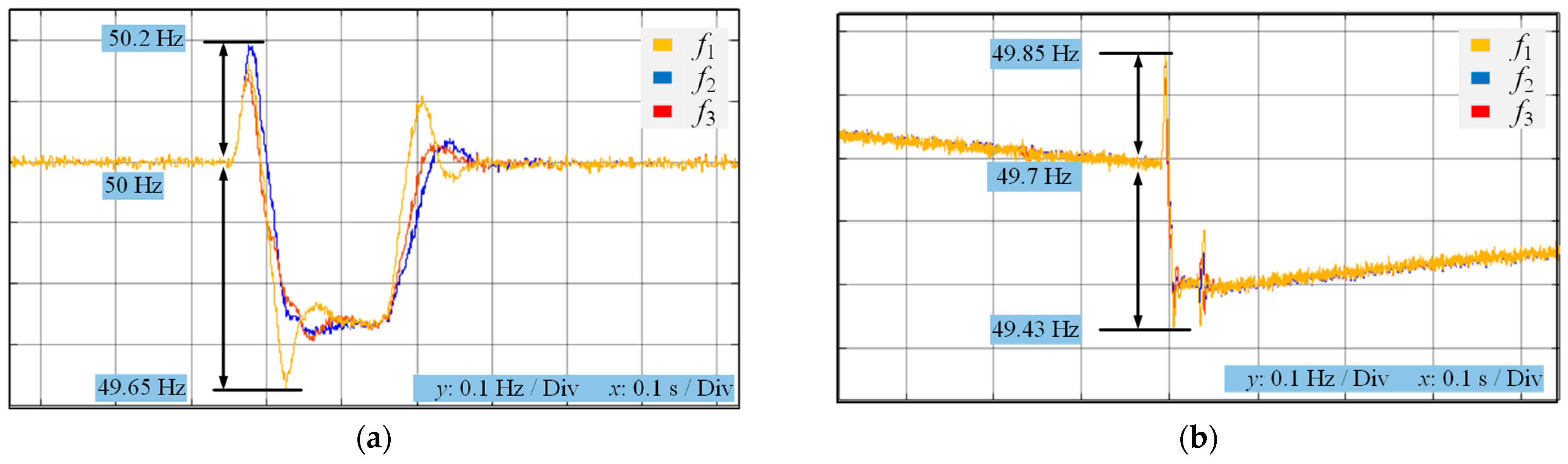
9.2. Frequency Restoration

This section presents the result of frequency restoration for the proposed control method, as compared against a conventional consensus-based control method. A time delay of td = 250 ms is emulated using the network emulated in LabVIEW. Figure 10a presents the results of frequency regulation using the proposed method. It is observed that due to the action of the proposed average estimators in the control scheme, the dynamics of frequency restoration are vastly improved. Following the load change transient that causes this frequency deviation, the frequency is restored back to the nominal value of 50 Hz within 300 ms. Figure 10b gives the results of frequency regulation using a conventional consensus-based control scheme. It can be seen that the system frequency suffers from deviations and inaccuracies with the presence of communication delays. The transient created by the load variation further deteriorates the frequency restoration.

10. Comparisons with Other Control Strategies

To verify the proposed scheme’s viability, a comprehensive comparison of the suggested control scheme with the conventional consensus-based approach is presented in this section. Multi-agent-based consensus control structures, as discussed in [19,26,27,30,33], need a mutual agreement between observers of the participating node to satisfy the objective of cooperative control. All of these above-mentioned techniques are highly dependent on the communication network’s health, so that desired convergence can be achieved in the MG parameters. Consensus-based control schemes are based on integral functions that employ a collective minimization of errors. Communication latencies cause localized errors that get magnified due to the integral effect of the consensus controllers, and the system values diverge, as may be observed in Figure 6b,d,f and Figure 7c,e,g. Conversely, the proposed scheme in this work takes the value of average estimates as the nominal value of references that are calculated with the aid of distributed averaging observers. The suggested estimation technique is resilient to communication latencies in transmission, as can be seen in Figure 6a,c,e and Figure 7b,c,e. In scenarios such as communication link failure and latency, the performance of the suggested control strategy is compared with existing control schemes, and it is observed that convergence to stable states in these scenarios can be achieved in a short duration of time, which shows that the proposed scheme is more robust. The proposed control scheme has exhibited higher system reliability in several aspects compared to the conventional consensus-based controls, as demonstrated in Table 5.

11. Conclusions

This work proposes a novel multi-agent moving average estimator to observe distributed system values and thereby reduce the effect of communication latencies in the communication and control network. These estimators are incorporated into a hierarchical control structure that regulates system parameters with active power sharing and voltage and frequency regulation. Mathematical models are derived for the MG system under the proposed method and other conventional consensus-based methods. The viability and superiority of the proposed scheme over other conventional methods is demonstrated using stability analyses derived from these mathematical models. Detailed case-wise simulation studies are carried out in MATLAB, and the results for these control schemes are compared. Furthermore, a lab-scale experimental test bench is implemented to verify the results from the simulation studies. The adopted verification methods collectively establish the efficacy of the proposed control scheme and its superiority over other conventional control schemes. The proposed control method is more resilient to disturbances caused by communication latencies and shows earlier convergence than conventional consensus-based methods.

Author Contributions

Conceptualization, W.J.A., K.H., M.T.F., A.F. and M.A.M.; Methodology, W.J.A., K.H., M.T.F., A.F. and M.A.M.; Validation, W.J.A.; Formal analysis, K.H., M.T.F., A.F. and M.A.M.; Investigation, W.J.A., K.H. and S.C.; Writing—original draft, W.J.A., K.H., M.T.F., A.F. and M.A.M.; Writing—review & editing, W.J.A., K.H., M.T.F., A.F., S.C., M.A.M. and D.A.U.; Supervision, M.A.M.; Funding acquisition, S.C. All authors have read and agreed to the published version of the manuscript.

Funding

This research received no external funding.

Institutional Review Board Statement

Not applicable.

Informed Consent Statement

Not applicable.

Data Availability Statement

Not applicable.

Conflicts of Interest

The authors declare no conflict of interest.

Appendix A. System Matrices

A N E T i = r l i n e i L l i n e i ω 0 ω 0 r l i n e i L l i n e i
A L o a d i = R L o a d i L L o a d i ω 0 ω 0 R L o a d i L L o a d i
B N E T i = I l i n e Q i I l i n e Q i
B 1 N E T i = ... 1 L l i n e i 0 ... 1 L l i n e i 0 ... ... 0 1 L l i n e i ...0 1 L l i n e i ... 2 × 2 m
B 1 L o a d i = ... 1 L L o a d i 0 ... 1 L L o a d i 0 ... ... 0 1 L L o a d i ...0 1 L L o a d i ... 2 × 2 m
B 2 L o a d i = I L o a d Q i I L o a d D i
A M G = A m g 1 B i n v R N M N e t B i n v R N M L o a d A m g 2 A N e t + B 1 N e t R N M N e t B 1 N e t R N M L o a d A m g 3 B 1 L o a d R N M N e t A l o a d + B 1 L o a d R N M L o a d
A m g 1 = A i n v + B i n v R N M i n v C i n v c
A m g 2 = B 1 N e t R N M i n v C i n v c + B 2 N e t C i n v ω
A m g 3 = B 1 L o a d R N M i n v C i n v c + B 2 L o a d C i n v ω
r p k i = λ i a k k
A i n v i = A P i 0 0 B P i B V 1 i C P v i 0 0 B V 2 i B C 1 i D V 1 i C P v i B C 1 i C V i 0 B C 1 i D V 2 i + B C 2 i B L C L 1 i D C 1 i D V 1 i C P v i + B L C L l i D C l i C V i B L C L i C C i A L C L i + B L C L 2 i [ T V i 1 00 ] B L C L 3 i C P w i B L C L l i ( D C 1 i D V 2 i + D C 2 i ) 13 × 13
B i ω com = B P ω com 0 0 0 13 × 1 T
C I N V ω i = [ C p ω 0 0 0 ] 1 x 13 ; i = 1 [ 0 0 0 0 ] 1 x 13 ; i 1
A P = 0 m p 0 0 ω c 0 0 0 ω c , B P ω com = 1 0 0 B P = 0 0 0 0 0 0 0 0 ω c I od ω c I oq ω c V od ω c I oq 0 0 ω c I oq ω c I od ω c V oq ω c V od
C P ω = 0 m P 0 , C Pv = 0 0 n Q 0 0 0
where Ainvi, Binvi, CINVωi, and Biωcom represent sub-matrices.

Appendix B

Appendix B.1. Adjacency Matrix

A g = 0 1 0 1 1 0 1 0 0 1 0 1 1 0 1 0

Appendix B.2. Degree Matrix

D g = 2 0 0 0 0 2 0 0 0 0 2 0 0 0 0 2

Appendix B.3. Laplacian Matrix

Λ g = D g A g = 2 1 0 1 1 2 1 0 0 1 2 1 1 0 1 2

References

  1. Guerrero, J.M.; Chandorkar, M.; Lee, T.L.; Loh, P.C. Advanced Control Architectures for Intelligent Microgridspart i: Decentralized and Hierarchical Control. IEEE Trans. Ind. Electron. 2013, 60, 1254–1262. [Google Scholar] [CrossRef] [Green Version]
  2. Ramos, F.; Pinheiro, A.; Nascimento, R.; de Araujo Silva Junior, W.; Mohamed, M.A.; Annuk, A.; Marinho, M.H. Development of Operation Strategy for Battery Energy Storage System into Hybrid AC Microgrids. Sustainability 2022, 14, 13765. [Google Scholar] [CrossRef]
  3. Mohamed, M.A. A relaxed consensus plus innovation based effective negotiation approach for energy cooperation between smart grid and microgrid. Energy 2022, 252, 123996. [Google Scholar] [CrossRef]
  4. Abouzeid, S.I.; Guo, Y.; Zhang, H. Coordinated Control of the Conventional Units, Wind Power, and Battery Energy Storage System for Effective Support in the Frequency Regulation Service. Int. Trans. Electr. Energy Syst. 2019, 29, e2845. [Google Scholar] [CrossRef]
  5. Bharti, D.; De, M. Framework for Multipoint Optimal Reactive Power Compensation in Radial Distribution System with High Distributed Generation Penetration. Int. Trans. Electr. Energy Syst. 2019, 29, e12007. [Google Scholar] [CrossRef]
  6. Han, H.; Hou, X.; Yang, J.; Wu, J.; Su, M.; Guerrero, J.M. Review of Power Sharing Control Strategies for Islanding Operation of AC Microgrids. IEEE Trans. Smart Grid 2016, 7, 200–215. [Google Scholar] [CrossRef] [Green Version]
  7. Han, Y.; Zhang, K.; Li, H.; Coelho, E.A.A.; Guerrero, J.M. MAS-Based Distributed Coordinated Control and Optimization in Microgrid and Microgrid Clusters: A Comprehensive Overview. IEEE Trans. Power Electron. 2018, 33, 6488–6508. [Google Scholar] [CrossRef] [Green Version]
  8. Han, Y.; Li, H.; Shen, P.; Coelho, E.A.A.; Guerrero, J.M. Review of Active and Reactive Power Sharing Strategies in Hierarchical Controlled Microgrids. IEEE Trans. Power Electron. 2017, 32, 2427–2451. [Google Scholar] [CrossRef] [Green Version]
  9. Guerrero, J.M.; Matas, J.; de Vicuna, L.G.; Castilla, M.; Miret, J. Decentralized Control for Parallel Operation of Distributed Generation Inverters Using Resistive Output Impedance. IEEE Trans. Ind. Electron. 2007, 54, 994–1004. [Google Scholar] [CrossRef]
  10. Guerrero, J.M.; De Vicuña, L.G.; Matas, J.; Miret, J.; Castilla, M. Output Impedance Design of Parallel-Connected UPS Inverters. IEEE Int. Symp. Ind. Electron. 2004, 2, 1123–1128. [Google Scholar] [CrossRef]
  11. Guerrero, J.M.; Matas, J.; De Vicuña, L.G.; Castilla, M.; Miret, J. Wireless-Control Strategy for Parallel Operation of Distributed-Generation Inverters. IEEE Trans. Ind. Electron. 2006, 53, 1461–1470. [Google Scholar] [CrossRef]
  12. Guerrero, J.M.; Vásquez, J.C.; Matas, J.; Castilla, M.; García de Vicuna, L. Control Strategy for Flexible Microgrid Based on Parallel Line-Interactive UPS Systems. IEEE Trans. Ind. Electron. 2009, 56, 726–736. [Google Scholar] [CrossRef]
  13. De Brabandere, K.; Bolsens, B.; Van Den Keybus, J.; Woyte, A.; Driesen, J.; Belmans, R. A Voltage and Frequency Droop Control Method for Parallel Inverters. IEEE Trans. Power Electron. 2004, 4, 2501–2507. [Google Scholar] [CrossRef]
  14. Alizadeh, E.; Birjandi, A.M.; Hamzeh, M. Decentralised Power Sharing Control Strategy in LV Microgrids under Unbalanced Load Conditions. IET Gener. Transm. Distrib. 2017, 11, 1613–1623. [Google Scholar] [CrossRef]
  15. Xia, Y.; Peng, Y.; Wei, W. Triple Droop Control Method for Ac Microgrids. IET Power Electron. 2017, 10, 1705–1713. [Google Scholar] [CrossRef]
  16. Hossain, M.A.; Pota, H.R.; Hossain, M.J.; Blaabjerg, F. Evolution of Microgrids with Converter-Interfaced Generations: Challenges and Opportunities. Int. J. Electron. Power Energy Syst. 2019, 109, 160–186. [Google Scholar] [CrossRef]
  17. Bidram, A.; Nasirian, V.; Davoudi, A.; Lewis, F.L. Droop-Free Distributed Control of AC Microgrids. IEEE Trans. Power Electron. 2016, 31, 1600–1617. [Google Scholar] [CrossRef] [Green Version]
  18. Bidram, A.; Member, S.; Davoudi, A.; Lewis, F.L.; Guerrero, J.M.; Member, S. Distributed Cooperative Secondary Control of Microgrids Using Feedback Linearization. IEEE Trans. Power Electron. 2013, 28, 3462–3470. [Google Scholar] [CrossRef] [Green Version]
  19. Lu, L.Y.; Chu, C.C. Consensus-Based Secondary Frequency and Voltage Droop Control of Virtual Synchronous Generators for Isolated AC Micro-Grids. IEEE J. Emerg. Sel. Top. Circuits Syst. 2015, 5, 443–455. [Google Scholar] [CrossRef]
  20. Wang, X.; Zhang, H.; Li, C. Distributed Finite-Time Cooperative Control of Droop-Controlled Microgrids under Switching Topology. IET Renew. Power Gener. 2017, 11, 707–714. [Google Scholar] [CrossRef]
  21. Sanjari, M.J.; Gharehpetian, G.B. Unified Framework for Frequency and Voltage Control of Autonomous Microgrids. IET Gener. Transm. Distrib. 2013, 7, 965–972. [Google Scholar] [CrossRef]
  22. Shahid, M.U.; Khan, M.M.; Xu, J.; Hashmi, K.; Habib, S.; Mumtaz, M.A.; Tang, H. A Hierarchical Control Methodology for Renewable Dc Microgrids Supporting a Variable Communication Network Health. Electronics 2018, 7, 418. [Google Scholar] [CrossRef] [Green Version]
  23. Lewis, F.L.; Qu, Z.; Davoudi, A.; Bidram, A. Secondary Control of Microgrids Based on Distributed Cooperative Control of Multi-Agent Systems. IET Gener. Transm. Distrib. 2013, 7, 822–831. [Google Scholar] [CrossRef] [Green Version]
  24. Liu, W.; Gu, W.; Xu, Y.; Wang, Y.; Zhang, K. General Distributed Secondary Control for Multi-Microgrids with Both PQ-Controlled and Droop-Controlled Distributed Generators. IET Gener. Transm. Distrib. 2017, 11, 707–718. [Google Scholar] [CrossRef]
  25. Zuo, S.; Davoudi, A.; Song, Y.; Lewis, F.L. Distributed Finite-Time Voltage and Frequency Restoration in Islanded AC Microgrids. IEEE Trans. Ind. Electron. 2016, 63, 5988–5997. [Google Scholar] [CrossRef]
  26. Guo, F.; Wen, C.; Mao, J.; Song, Y.D. Distributed Secondary Voltage and Frequency Restoration Control of Droop-Controlled Inverter-Based Microgrids. IEEE Trans. Ind. Electron. 2015, 62, 4355–4364. [Google Scholar] [CrossRef]
  27. Agundis-Tinajero, G.; Segundo-Ramírez, J.; Visairo-Cruz, N.; Savaghebi, M.; Guerrero, J.M.; Barocio, E. Power Flow Modeling of Islanded AC Microgrids with Hierarchical Control. Int. J. Electr. Power Energy Syst. 2019, 105, 28–36. [Google Scholar] [CrossRef] [Green Version]
  28. Lu, X.; Yu, X.; Lai, J.; Guerrero, J.M.; Zhou, H. Distributed Secondary Voltage and Frequency Control for Islanded Microgrids With Uncertain Communication Links. IEEE Trans. Ind. Inform. 2017, 13, 448–460. [Google Scholar] [CrossRef] [Green Version]
  29. Wang, Y.; Wang, X.; Chen, Z.; Blaabjerg, F. Distributed Optimal Control of Reactive Power and Voltage in Islanded Microgrids. IEEE Trans. Ind. Appl. 2017, 53, 340–349. [Google Scholar] [CrossRef]
  30. Hashmi, K.; Khan, M.M.; Habib, S.; Tang, H. An Improved Control Scheme for Power Sharing between Distributed Power Converters in Islanded AC Microgrids. In Proceedings of the 2017 International Conference on Frontiers of Information Technology (FIT), Islamabad, Pakistan, 18–20 December 2017; IEEE: Piscataway, NJ, USA; pp. 270–275. [Google Scholar]
  31. Hashmi, K.; Mansoor Khan, M.; Jiang, H.; Umair Shahid, M.; Habib, S.; Talib Faiz, M.; Tang, H. A Virtual Micro-Islanding-Based Control Paradigm for Renewable Microgrids. Electronics 2018, 7, 105. [Google Scholar] [CrossRef]
  32. Schiffer, J.; Seel, T.; Raisch, J.; Sezi, T. Voltage Stability and Reactive Power Sharing in Inverter-Based Microgrids with Consensus-Based Distributed Voltage Control. IEEE Trans. Control Syst. Technol. 2016, 24, 96–109. [Google Scholar] [CrossRef] [Green Version]
  33. Guan, Y.; Meng, L.; Li, C.; Vasquez, J.; Guerrero, J. A Dynamic Consensus Algorithm to Adjust Virtual Impedance Loops for Discharge Rate Balancing of AC Microgrid Energy Storage Units. IEEE Trans. Smart Grid 2017, 3053, 4847–4860. [Google Scholar] [CrossRef] [Green Version]
  34. Lai, J.; Zhou, H.; Lu, X.; Yu, X.; Hu, W. Droop-Based Distributed Cooperative Control for Microgrids with Time-Varying Delays. IEEE Trans. Smart Grid 2016, 7, 1775–1789. [Google Scholar] [CrossRef]
  35. Hashmi, K.; Khan, M.M.; Shahid, M.U.; Nawaz, A.; Khan, A.; Jun, J.; Tang, H. An Energy Sharing Scheme Based on Distributed Average Value Estimations for Islanded AC Microgrids. Int. J. Electr. Power Energy Syst. 2020, 116, 105587. [Google Scholar] [CrossRef]
  36. Hashmi, K.; Khan, M.M.; Xu, J.; Shahid, M.U.; Habib, S.; Faiz, M.T.; Tang, H. A Quasi-Average Estimation Aided Hierarchical Control Scheme for Power Electronics-Based Islanded Microgrids. Electronics 2019, 8, 39. [Google Scholar] [CrossRef] [Green Version]
  37. Bidram, A.; Nasirian, V.; Davoudi, A.; Lewis, F.L. Cooperative Synchronization in Distributed Microgrid Control, 1st ed.; Grimble, M.J., Ed.; Springer International Publishing: Cham, Switzerland, 2017; ISBN 978-3-319-50807-8. [Google Scholar]
  38. Coelho, E.A.A.; Wu, D.; Guerrero, J.M.; Vasquez, J.C.; Dragičević, T.; Stefanović, Č.; Popovski, P. Small-Signal Analysis of the Microgrid Secondary Control Considering a Communication Time Delay. IEEE Trans. Ind. Electron. 2016, 63, 6257–6269. [Google Scholar] [CrossRef] [Green Version]
  39. Mahmoud, M.S.; AL-Sunni, F.M. Control and Optimization of Distributed Generation Systems, 1st ed.; Springer International Publishing: Berlin/Heidelberg, Germany, 2015; ISBN 978-3-319-16909-5. [Google Scholar]
  40. Shenoi, B.A. Introduction to Digital Signal Processing and Filter Design, 1st ed.; John Wiley & Sons, Inc.: Hoboken, NJ, USA, 2006; ISBN 13 978-0-471-46482-2. [Google Scholar]
  41. Nasirian, V.; Moayedi, S.; Davoudi, A.; Lewis, F.L. Distributed Cooperative Control of Dc Microgrids. IEEE Trans. Power Electron. 2015, 30, 2288–2303. [Google Scholar] [CrossRef]
  42. Mariani, V.; Vasca, F.; Vsquez, J.C.; Guerrero, J.M. Model Order Reductions for Stability Analysis of Islanded Microgrids With Droop Control. IEEE Trans. Ind. Electron. 2015, 62, 4344–4354. [Google Scholar] [CrossRef]
  43. Mathworks Simulink Reference, R2019a ed.; The MatWorks Inc.: Natick, MA, USA, 2019.
Figure 1. Control and power distribution network of the AC microgrid.
Sustainability 15 01579 g001
Figure 2. Representation of the distributed control scheme. (a) Secondary regulation; (b) Fully connected bidirectional communication structure; (c) Partially connected communication structure with latencies.
Sustainability 15 01579 g002aSustainability 15 01579 g002b
Figure 3. Control levels. (a) Power controller (primary control); (b) Distributed multi-agent moving average power estimator (secondary control); (c) Voltage control loop (zero level control); (d) Current control loop (zero level control).
Sustainability 15 01579 g003
Figure 4. A comparison of stability under the proposed and other methods. (a) Effect of mP variation with proposed average estimators; (b) nQ variation with proposed average estimators; (c) mP variation with consensus-based observers; (d) nQ variation with consensus-based observers.
Sustainability 15 01579 g004aSustainability 15 01579 g004b
Figure 5. Comparative effect of the time delay on system stability. (a) Proposed distributed averaging method; (b) Distributed averaging method (magnified); (c) Estimation of values based on consensus; (d) Estimation of values method based on consensus (magnified).
Sustainability 15 01579 g005
Figure 6. Control schemes’ performance under time delays. (a) Time delays; (b) Distribution of active power using the proposed method; (c) Distribution of active-power using consensus method; (d) Frequency restoration with proposed method; (e) Frequency restoration with consensus-based method; (f) Voltage restoration with proposed method; (g) Voltage restoration with consensus method.
Sustainability 15 01579 g006
Figure 7. Experimental layout. (a) Experimental set-up; (b) Communication network structure.
Sustainability 15 01579 g007
Figure 8. Experimental set-up.
Sustainability 15 01579 g008
Figure 9. Performance of power distribution controllers. (a) Consensu-based controls; (b) Proposed observer-based control.
Sustainability 15 01579 g009
Figure 10. Frequency performance of the controllers. (a) Frequency restoration using proposed control method; (b) Frequency restoration using consensus controls.
Sustainability 15 01579 g010
Table 1. Microgrid parameters.
ParameterValueParameterValue
Lf1.35 mHmp4.4 × 10−6
Rf0.1 Ωnq1.1 × 10−6
Cf25 µFkpf0.4
Lc1.35 mHkif0.5
Rc0.05 ΩkpV0.6
Rline0.2 ΩkiV0.3
Lline0.6 mHF0.6
fnom50 Hzωc31.4
Vnom380 VL-L
Table 2. System loads.
Bus No.Loads Connected (p.u)
PQ
100
20.30.3
30.250.25
40.250.25
500
Table 3. Range of variation for controllers with time delays.
Serial. No.Control Parameters
1.Power ControllerMinimumMaximum
Active power: mp 1 × 10 10 1 × 10 3
Reactive power: nq 1 × 10 7 1 × 10 3
2.Frequency regulation
kpf0.452.55
kif0.140.53
3.Voltage regulation
kpV0.513.52
kiV0.150.53
4.Communication time delay: τdelay02 s
Table 4. Experimental control parameters.
ParametersSymbolValues
System frequency (nominal)f*50 Hz
System voltage (nominal)V*100 V
Switching frequencyfs16 kHz
DC link voltageVDC150 V
Zero level controllersVoltage loop controllerKpV123
KiV155
Current loop controllerKpC142
KiC1110
Primary controllersActive power controllermp10.0035 rad /Watt
Reactive power controllernQ110−4 rad /VA
Secondary controllersVoltage restorative controllerKpVr2.5
KiVr0.5
Frequency restorative controllerKpfr3.5
Kifr0.8
Quasi-average observera0.7
Communication delaytd10 ms (min)–2000 ms (max)
Table 5. Comparisons of control schema under communication latencies.
Comparison ParametersProposed Multi-Agent Moving Average MethodConsensus-Based Methods
[18,25,26,29,32]
Active power sharingConvergence achieved in small time intervalConvergence in larger time interval
Voltage variations Small variations have been observed that decay in small period of timeLarger variations that decay in longer period of time
Frequency variations Small variations that decay in small period of timeLarger variations that decay in longer period of time
Convergence: frequencyAchieved in small timeAchieved in medium time
Convergence: voltageAchieved in small timeAchieved in larger time
Disclaimer/Publisher’s Note: The statements, opinions and data contained in all publications are solely those of the individual author(s) and contributor(s) and not of MDPI and/or the editor(s). MDPI and/or the editor(s) disclaim responsibility for any injury to people or property resulting from any ideas, methods, instructions or products referred to in the content.

