

Active and Reactive Power Control of the Voltage Source Inverter in an AC Microgrid

1
Department of Electronics & Power Engineering, PN Engineering College, National University of Science and Technology, Karachi 75350, Pakistan
2
Department of Electrical Engineering, Iqra University, Karachi 75500, Pakistan
*
Author to whom correspondence should be addressed.
Sustainability 2023, 15(2), 1621; https://doi.org/10.3390/su15021621
Submission received: 19 October 2022
/
Revised: 7 January 2023
/
Accepted: 12 January 2023
/
Published: 13 January 2023
(This article belongs to the Topic Advances in Renewable Energy Technologies and Systems Solutions)
Abstract
:This paper presents the mathematical model and control of a voltage source inverter (VSI) connected to an alternating current (AC) microgrid. The VSI considered in this paper is six switches three-phase Pulse Width Modulated (PWM) inverter, whose output active and reactive power is controlled in the reference frame. The control strategy presented here is state feedback control with disturbance cancellation. This disturbance signal is either provided by a voltage sensor or estimated using a presented extended high gain observer (EHGO). The control strategy without EHGO requires a current sensor and a voltage sensor, and the control strategy with EHGO requires only a current sensor. The EHGO is saving the requirement of a voltage sensor. The stability analysis of the presented control strategy is showing that the error is ultimately bounded in the presence of disturbance, formed due to Pulse Width Modulated (PWM) inverters. The microgrid is simulated using the SimPowerSystems Toolbox of MATLAB/Simulink. The simulation results are also showing the effectiveness of the proposed control strategy, that the output active and reactive power control is achieved with ultimately bounded errors. The comparison of the proposed control with the PI-based control scheme is also presented, and it is shown that better reference tracking with the desired settling time of “0.04 s” is achieved with the proposed control.
1. Introduction
The smart grid is considered to be the future of electricity network and the microgrid is an important part of it [1,2,3]. Microgrid enables the integration of distributed generation units (DG units) at the distribution level [4,5]. The use of DG units at the distribution level provides many advantages like less loss in power transmission from generation to consumption. The microgrid also allows the islanded operation, in case of power failure from the main grid. There are many challenges involved in the integration of DG units at the distribution level that need to be solved [6,7,8]. The voltage source inverter (VSI) is the key element for integrating DG units in microgrid [9,10,11]. Proper control mechanisms on VSI are required for voltage and frequency stability and for proper power sharing among multiple DG units in a microgrid [12]. A microgrid can be operated in either grid-connected mode or in islanded mode [13,14,15], and VSI can be controlled in either voltage control mode (VCM) or in power control mode (PCM) [16]. In the islanded mode of operation, either all VSIs operate in VCM with power sharing achieved by solving optimal power flow equations [17,18] or by using the droop control method [19,20,21] or by operating in a master-slave configuration. In the master-slave configuration, a master VSI operates in VCM, and other VSIs operate in PCM [22,23]. In grid-connected mode, the grid works as “swing” for optimal power flow equations with all DG units operating in VCM; or in a master-slave configuration, the grid works as a master unit with all DG units operating in PCM. The control systems for VCM or PCM can be designed in a natural () reference frame, stationary () reference frame, or synchronous () reference frame [24]. Signals in these reference frames can be converted using Clarke and Park transformations [25]. DG units and loads frequently join and leave the microgrid resulting in a change in topology, so the control system must work on locally available signals [26].
This paper focuses on the control system design of a voltage source inverter (VSI) in power control mode (PCM). Many control techniques have been presented in the literature on this problem. In [27], PI controller-based active and reactive power control is shown in the reference frame. This controller uses two control loops for both active and reactive power control. This makes the tuning of the controller difficult. In [28], the power control strategy is presented for photovoltaic and battery storage-based inverters in the AC microgrid. It utilizes the multiple loops of PI control to achieve active and reactive power control in the reference frame. In [29], a power controller is presented to improve the power quality of the grid-connected inverter. The power controller is designed in reference frame, and it generates the reference values for the current controller. The current controller is a hysteresis-based PWM controller designed in reference frame. A direct active and reactive power control of grid-tied inverter is presented in [30]. The fuzzy logic-based controller is designed to minimize the errors between active and reactive powers and their reference values. In [31], an artificial neural network (ANN) based power control is presented to enhance the power quality of a photovoltaic-based inverter connected to a grid-tied AC microgrid. An optimal controller is designed for power control of VSI connected in a grid-tied microgrid [32]. The controller parameters are obtained by using particle swarm optimization (PSO) to minimize a cost function. In [33], a power control strategy based on cascaded voltage-current control is presented. In this voltage-current control, the disturbance signal containing grid and load current is also estimated and compensated. A sliding mode controller-based power control is presented in [34]. The controller is designed in a reference frame for a grid-connected inverter. In [35], the power control of the inverter connected to islanded microgrid is presented. Sliding mode control is presented to provide robustness against external disturbances, including communication failures. In [36], a voltage-oriented power coordination control is presented for a grid-tied inverter in an AC microgrid. An active and reactive power control strategy are shown in [37]. The P-V and Q-f droop curves provided the reference values for cascaded voltage-current controllers. The control is implemented in the reference frame. In [38], a power control strategy is presented for VSI in a grid-tied microgrid. In [39], a model predictive control incorporated with the droop method is shown for load sharing in an AC microgrid. A particle swarm optimization (PSO) is also implemented to find the optimal required active and reactive power reference values of inverters to minimize the operational cost of the microgrid. Active and reactive power control is presented in [40] for grid-connected microinverter. The control design is implemented in the reference frame. In [41], voltage support and harmonic compensation are provided in a grid-connected microgrid by active and reactive power control. Using the PI control, a reference for the current controller is generated in the reference frame, which is controlled by a PR controller. An adaptive fractional fuzzy sliding mode control (AFFSMC) is presented to regulate active and reactive power injected by DG unit into a grid-connected microgrid in [42]. In a microgrid, the controllers of all VSIs need a synchronization signal, which is provided by a global positioning system (GPS) [43].
Most literature on power control is on grid-connected microgrids, where the voltage at the point of common coupling (PCC) is maintained by the main grid. The voltage provided by the main grid does not have disturbances related to the PWM inverter, whereas in the islanded microgrid the voltage is maintained by the master VSI. Due to the voltage at PCC maintained by a PWM inverter in islanded mode, the decoupling of active and reactive power is difficult. This paper presents a state feedback controller with disturbance cancellation for VSI control in power control mode (PCM), connected to an islanded AC microgrid. This control strategy utilizes only a three-phase current and a three-phase voltage sensor. The disturbance is also estimated using an extended high gain observer (EHGO). This EHGO-based control utilizes only a current sensor for active and reactive power control of the DG unit. Stability analyses and simulation results have shown the effectiveness of the proposed control scheme. The contribution of the presented work lies in the direct active and reactive power control in the presence of non-constant disturbance due to PCC voltage maintained by another PWM inverter working as master VSI. Another contribution is the estimation of this disturbance by EHGO; this EHGO-based control uses only a three-phase current sensor and saves the requirement of a voltage sensor.
2. Problem Formulation
The voltage source inverter (VSI) is shown in Figure 1. The VSI in this figure is six switches PWM inverter with an output filter. The filter reduces the harmonics from the VSI’s output PWM voltages. In this figure, all signals are represented in the reference frame. Here, is the VSI input signal, to be compared with a triangular carrier wave to produce the gating signals. The gating signals apply on PWM inverter switches to produce the PWM signals. is filter input current, is filter output current and is filter output voltage. is also the current injected into the microgrid from VSI. , , and are the resistance, capacitance, and inductance of the VSI output filter, respectively. The VSI is connected to the microgrid at the point of common coupling (PCC).
The signals shown in Figure 1 are three-phase signals, represented in reference frame, and can be converted into reference frame using the park’s transformation. The signals in the reference frame and reference frame are linked as follows:
The system shown in Figure 1 can be mathematically represented in the reference frame by the following dynamical equations [44]. Here, is the angular frequency of the system.
The active power () and reactive power () delivered into the microgrid by the VSI are calculated as follows:
The problem considered in this paper is to control the active power () and reactive power () delivered into the microgrid by VSI in the reference frame and minimize the following tracking error signals to an ultimate bound in finite time. The control signals generated by the controller will be the variables and . The reference signals for active power and reactive power are and , respectively.
3. Control Scheme
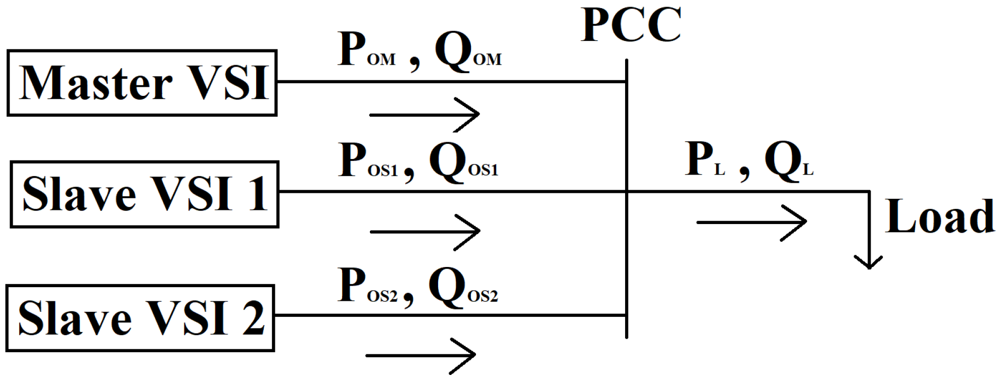
System shown in Equations (1a)–(1d) and (2) is a multiple-input multiple-output system, with input variables and output variables . As shown in Figure 2, a microgrid of three parallel connected VSI in master/slave configuration is presented here. Master VSI works in VCM and controls the voltages, whereas slave VSIs work in PCM and control its output active and reactive power .
Considering the power control problem for a slave VSI, the voltages considered at PCC are as follows:
The voltage values given in Equation (4) are steady-state values, but using these values within transient period reduces the requirement of a current sensor.
Using Equation (4) values with Equations (1a) and (1c) provide the following relations between filter’s input current and current injected into the microgrid .
Using Equations (4) and (5) with Equation (2) gives following equations to calculate the output active () and reactive powers ().
Using Equation (9), can be calculated using only . From Equation (6), the relative degree of system is 1. Only Equation (1b) is required for controller design of active power () and Equation (1d) is required for controller design of reactive power ().
3.1. Controller Design for Active Power ()
The controller for active power () can be designed in error coordinates by assuming the following variables:
, , , ,
The system in error coordinates is as follows:
The system shown in Equation (7) can be stabilized by the control equation given below for the properly chosen values of and .
The controller shown in Equation (8) requires current signals and a voltage signal . To save the requirement of a voltage sensor for , is estimated using extended high gain observer (EHGO) [45] as follows. Let
; is the nominal value of
The system shown in Equation (7) can be converted into an augmented system as follows:
The EHGO for the augmented system in Equation (9) is as follows:
Here for , . In addition, is an estimate of , which can be used in the following control equation saving the requirement of a voltage sensor. The EHGO-based control equation is as follows:
is the bound on the control signal, calculated as follows:
3.2. Controller Design for Reactive Power ()
The controller for reactive power () can be designed in error coordinates by assuming the following variables:
, , , ,
The system in error coordinates is as follows:
The system shown in Equation (13) can be stabilized by the control equation given below for the properly chosen values of and .
The controller shown in Equation (14) requires current signals and a voltage signal . To save the requirement of a voltage sensor for , is estimated using EHGO [45] as follows. Let
; is the nominal value of
The system shown in Equation (13) can be converted into an augmented system as follows:
The EHGO for the augmented system in Equation (15) is as follows:
Here for , . In addition, is an estimate of , which can be used in the following control equation saving the requirement of a voltage sensor. The EHGO-based control equation is as follows:
is the bound on the control signal, calculated as follows:
4. Stability Analyses
For the systems in Equations (7) and (13), with designed controllers in Equations (8) and (14), the closed loop error dynamics are shown below in Equation (19). Equation (19) clearly shows that error will asymptotically go to zero for properly chosen values of and .
Similarly, for the systems in Equations (7) and (13), with designed controllers in Equations (11) and (17), the closed loop error dynamics are shown below in Equation (20) for and .
Here in Equations (19) and (20); and in following equations, and for active power control system, and for reactive power control system.
For the following desired closed-loop characteristic Equation (21):
and are calculated as follows:
in Equation (20) is the estimation error of EHGO. Equation (20) clearly shows that the error will go to zero if the following condition holds.
The condition in Equation (23) does not hold due to the PWM inverter, so there will be some difference in the performance of the controller without EHGO (Equations (8) and (14)) and with EHGO (Equations (11) and (17)).
The estimation errors are
From systems in Equations (9) and (15) with EHGO in Equations (10) and (16), the estimation error dynamics are as follows:
The transfer function from to is
The above transfer function in Equation (25) clearly shows that estimation error goes to zero, as goes to zero. This can also be shown in the time domain using scaled estimation errors:
The scaled estimation error dynamics are as follows:
Here, it is clearly shown that the estimation error goes to zero as goes to zero if the following Equation (27) has all roots with a negative real part.
The transient response of EHGO suffers from the peaking phenomenon [45]. The adverse effects of the peaking phenomenon on system states can be avoided by using saturated control signals as shown in Equations (8), (11), (14), and (17).
With PWM inverter, in Equation (20) can not be brought to zero but can be reduced for a properly chosen value of .
5. Simulation Results
In this section, a microgrid of three VSIs and a load shown in Figure 2 is simulated by using the SimPowerSystems toolbox of Matlab/Simulink. All VSIs in this microgrid are identical, and their electrical parameters are shown in Table 1.
In Figure 2, the control system of master VSI controls the voltage at PCC and tracks the following reference voltages shown in Equation (28). The control scheme of master VSI is discussed in [18].
The slave VSIs control their active and reactive power output and track the reference values shown in Table 2. Master VSI delivers the remaining power required by the load. The controller and EHGO parameters of slave VSIs are shown in Table 3. The controller parameters are found by Equations (21) and (22) to achieve the desired settling time of “ s”. and are found by inequalities (12) and (18), respectively.
The microgrid shown in Figure 2 is first simulated using the controller Equations (8) and (14) for slave VSIs. These controller equations are not using the EHGO, which means it requires a current sensor for signals and a voltage sensor for signals . The simulation results show that the error is ultimately bounded in finite time. The output voltages at PCC in the reference frame are shown in Figure 5. It can be seen in Figure 5 that master VSI is effectively tracking its reference signals. The current delivered by the inverters in the reference frame is shown in Figure 6. The change in the current amplitude is according to the power delivered by VSIs. The active power injected by the master and slave VSIs is shown in Figure 7. The reactive power injected by the master and slave VSIs is shown in Figure 8. The reference tracking by the controllers of the slave VSIs can be seen in Figure 7 and Figure 8. This active and reactive power delivery is shown in Table 2 and clearly shows the effectiveness of the control strategy presented in Equations (8) and (14). The steady-state performance is showing that the error is ultimately bounded; active power of slave VSIs is tracking its reference signals and reactive power of slave VSIs is also tracking its reference signals , with also achieving the desired transient performance, i.e., settling time of “0.04 s”.
The microgrid shown in Figure 2 is again simulated using the controller Equations (11) and (17) for slave VSIs. These controller equations used from the EHGO Equations (10) and (16), instead of which saves the requirement of a voltage sensor for signals . This EHGO-based controller requires only a current sensor for signals . The simulation results of this EHGO-based control show that the error is still ultimately bounded with some difference in transient response compared to non-EHGO-based control. The output voltages at PCC in the reference frame of this EHGO-based control are shown in Figure 9. The current delivered by the inverters in the reference frame is shown in Figure 10. The active power and reactive power delivered by VSIs are shown in Figure 11 and Figure 12, respectively. The steady-state performance of this EHGO-based control is similar to non-EHGO-based control, and only the initial transient performance is compromised. This initial change in transient performance is due to the transient response of EHGO.
To show the performance of the control scheme with sudden load change, the microgrid shown in Figure 2 is simulated with non-EHGO-based control (Equations (8) and (14)) and EHGO-based control (Equation (11) and (17)). Slave VSI 1 will track its reference signals of 7 KW and 7 KVAR. Slave VSI 2 will track its reference signals of 5 KW and 5 KVAR. The master VSI will deliver the remaining active and reactive power. The simulation results of both non-EHGO-based and EHGO-based control clearly show that slave VSIs are tracking their reference signals, and any sudden power change in load is delivered by the master VSI. The current delivered by the inverters in the reference frame of non-EHGO-based control is shown in Figure 13. It can be seen that the current of slave VSIs remains the same and only the master VSI current has changed. The active power and reactive power delivered by VSIs and drained by the load are shown in Figure 14. The simulation results are showing that with a given control strategy, the microgrid is able to handle sudden changes in load. The EHGO-based control also shows the effective handling of sudden load changes in the microgrid. The current delivered by the inverters in the reference frame of EHGO-based control is shown in Figure 15. The active power and reactive power delivered by VSIs and drained by the load are shown in Figure 16.
The proposed control design of non-EHGO-based and EHGO-based are also compared with the PI-based control scheme shown in Figure 17. It is a cascaded power and current control based on PI controllers. The proportional and integral gains of the current controllers are 1. The current controllers track the reference signals , generated by the PI controllers of power control. The PI controllers of power control track the reference signals of required active and reactive powers . The proportional and integral gains of the power controllers are 0.1 and 0.3, respectively. The microgrid shown in Figure 2 is simulated with the required power-sharing shown in Table 2. This PI control scheme has been widely used to eliminate steady-state error but eliminating the steady-state error with the required transient response is very difficult to achieve. The comparison of the active power reference tracking of the slave VSIs is shown in Figure 18, and the reactive power reference tracking comparison of the slave VSIs is shown in Figure 19. In Figure 18 and Figure 19, it can be seen that the proposed control designs gave better reference tracking as compared to the PI control scheme, in terms of eliminating the steady-state error with achieving the desired transient response. Here, the proposed non-EHGO-based control used only a current sensor and a voltage sensor, the proposed EHGO-based control used only a current sensor; whereas the PI control scheme required two current sensors and a voltage sensor. Thus, the proposed control designs also save the requirement of extra sensors.
6. Conclusions
In this paper, active and reactive power control of a VSI is considered, with the microgrid working in a master/slave configuration. The active and reactive power controllers are designed in the reference frame for slave VSIs. The control strategy presented is state feedback control with disturbance cancellation. An extended high-gain observer (EHGO) based disturbance estimator is also presented. The control strategy without EHGO requires a three-phase current and a three-phase voltage sensor, whereas the control strategy with EHGO requires only a current sensor. The stability analyses and simulation results have clearly shown the effectiveness of the proposed control design. The required settling time of “0.04 s” is also achieved. The comparison of the proposed control design with the PI control-based power control is presented and clearly shows that the presented control design gave better performance. This paper provided the microgrid power control in master/slave configuration for the linear load. This work can be extended for nonlinear loads. The microgrid considered here is a one-bus microgrid, in which VSIs are connected to PCC, and voltage is controlled by the master VSI. This work can also be extended to microgrids consisting of multiple buses.
Author Contributions
A.Y.M. conceived the idea of the work. H.S.K. and A.Y.M. jointly worked on the control design, extended high gain observer design, and stability analyses. H.S.K. performed the relevant computer simulations. H.S.K. wrote the manuscript; all research work was supervised by A.Y.M. All authors have read and agreed to the submitted version of the manuscript.
Funding
This research received no external funding.
Data Availability Statement
No new data were created or analyzed in this study. Data sharing is not applicable to this article.
Conflicts of Interest
The authors declare no conflict of interest.
Abbreviations
The following abbreviations are used in this manuscript:
| VSI | voltage source inverter |
| PWM | pulse width modulated |
| PCC | point of common coupling |
| VCM | voltage control mode |
| PCM | power control mode |
| EHGO | extended high-gain observer |
References
- Deng, F.; Li, X.; Zhang, X.; Mattavelli, P. An Iterative Virtual Impedance Regulation Strategy in Islanded Microgrids for Enhanced Balanced, Unbalanced and Harmonic Current Sharing. IEEE Trans. Sustain. Energy 2022, 13, 514–526. [Google Scholar] [CrossRef]
- Bullich-Massagué, E.; Aragüés-Peñalba, M.; Prieto-Araujo, E.; Sumper, A.; Caire, R. Optimal feeder flow control for grid connected microgrids. Int. J. Electr. Power Energy Syst. 2019, 112, 144–155. [Google Scholar] [CrossRef]
- Farrokhabadi, M.; Cañizares, C.A.; Simpson-Porco, J.W.; Nasr, E.; Fan, L.; Mendoza-Araya, P.A.; Tonkoski, R.; Tamrakar, U.; Hatziargyriou, N.; Lagos, D.; et al. Microgrid stability definitions, analysis, and examples. IEEE Trans. Power Syst. 2019, 35, 13–29. [Google Scholar] [CrossRef]
- Chen, Z.; Pei, X.J.; Yang, M.; Peng, L. An adaptive virtual resistor (avr) control strategy for low-voltage parallel inverters. IEEE Trans. Power Electron. 2019, 34, 863–876. [Google Scholar] [CrossRef]
- Andishgar, M.H.; Gholipour, E.; Hooshm, R.A. An overview of control approaches of the inverter-based microgrids in islanding mode of operation. Renew. Sustain. Energy Rev. 2017, 80, 1043–1060. [Google Scholar] [CrossRef]
- Worku, M.Y.; Hassan, M.A.; Abido, M.A. Real Time-Based under Frequency Control and Energy Management of Microgrids. Electronics 2020, 9, 1487. [Google Scholar] [CrossRef]
- Hossain, M.A.; Pota, H.R.; Hossain, M.J.; Blaabjerg, F. Evolution of microgrids with converter-interfaced generations: Challenges and opportunities. Int. J. Electr. Power Energy Syst. 2019, 109, 160–186. [Google Scholar] [CrossRef]
- Zhou, Y.; Ho, C.N.-M. A review on microgrid architectures and control methods. In Proceedings of the 8th International Power Electronics and Motion Control Conference (IPEMC-ECCE Asia, Hefei, China, 22–26 May 2016; pp. 3149–3156. [Google Scholar]
- Guo, W.; Mu, L. Control principles of micro-source inverters used in the microgrid. Prot. Control Mod. Power Syst. 2016, 1, 1–7. [Google Scholar] [CrossRef] [Green Version]
- Das, P.P.; Chattopadhayay, S.; Palma, M.l. A d–q voltage droop control method with dynamically phase-shifted phase-locked loop for inverter paralleling without any communication between individual inverters. IEEE Trans. Ind. Electron. 2017, 64, 4591–4600. [Google Scholar] [CrossRef]
- Zhong, Q.C.; Zeng, Y. Universal droop control of inverters with different types of output impedance. IEEE Access 2016, 4, 702–712. [Google Scholar] [CrossRef]
- Wai, R.J.; Zhang, Q.Q.; Wang, Y. A novel voltage stabilization and power sharing control method based on virtual complex impedance for an off-grid microgrid. IEEE Trans. Power Electron. 2019, 34, 1863–1880. [Google Scholar] [CrossRef]
- Amin, M.; Zhong, Q.C. Resynchronization of distributed generation based on the universal droop controller for seamless transfer between operation modes. IEEE Trans. Ind. Electron. 2020, 67, 7574–7582. [Google Scholar] [CrossRef] [Green Version]
- Rezaei, N.; Mazidi, M.; Gholami, M.; Mohiti, M. A new stochastic gain adaptive energy management system for smart microgrids considering frequency responsive loads. Energy Rep. 2020, 6, 914–932. [Google Scholar] [CrossRef]
- Saad, N.H.; El-Sattar, A.A.; Mansour, A.E.-A.M. A novel control strategy for grid connected hybrid renewable energy systems using improved particle swarm optimization. Ain Shams Eng. J. 2018, 9, 2195–2214. [Google Scholar] [CrossRef]
- Rocabert, J.; Luna, A.; Blaabjerg, F.; Rodríguez, P. Control of Power Converters in AC Microgrids. IEEE Trans. Power Electron. 2012, 27, 4734–4749. [Google Scholar] [CrossRef]
- Kothari, D.P.; Nagrath, I.J. Modern Power System Analysis; Tata McGraw-Hill: New York, NY, USA, 2003. [Google Scholar]
- Khan, H.S.; Memon, A.Y. Robust Output Feedback Control of the Voltage Source Inverter in an AC Microgrid. Energies 2022, 15, 5586. [Google Scholar] [CrossRef]
- Jabr, R.A. Economic Operation of Droop-Controlled AC Microgrids. IEEE Trans. Power Syst. 2022, 37, 3119–3128. [Google Scholar] [CrossRef]
- Chen, J.B.; Yue, D.; Dou, C.X.; Chen, L.; Weng, S.X.; Li, Y.M. A virtual complex impedance based P over dot droop method for parallel-connected inverters in low-voltage ac microgrids. IEEE Trans. Ind. Inform. 2021, 17, 1763–1773. [Google Scholar]
- Razi, R.; Iman-Eini, H.; Hamzeh, M. An impedance-power droop method for accurate power sharing in islanded resistive microgrids. IEEE J. Emerg. Sel. Top. Power Electron. 2020, 8, 3763–3771. [Google Scholar] [CrossRef]
- Elnady, A.; Suleiman, M.S. Comparative Analysis of Direct and Indirect Current Control of Master-Slave Scheme for Microgrid. In Proceedings of the 2022 International Conference on Power Energy Systems and Applications (ICoPESA), Singapore, 25–27 February 2022; pp. 83–89. [Google Scholar] [CrossRef]
- Parisio, A.; Rikos, E.; Glielmo, L.A. Model Predictive Control Approach to Microgrid Operation Optimization. IEEE Trans. Control Syst. Technol. 2014, 22, 1813–1827. [Google Scholar] [CrossRef]
- Blaabjerg, F.; Teodorescu, R.; Liserre, M.; Timbus, A.V. Overview of Control and Grid Synchronization for Distributed Power Generation Systems. IEEE Trans. Ind. Electron. 2006, 53, 1398–1409. [Google Scholar] [CrossRef] [Green Version]
- Chattopadhyay, S.; Mitra, M.; Sengupta, S. Clarke and Park Transform. In Electric Power Quality Power Systems; Springer: Dordrecht, The Netherlands, 2011. [Google Scholar] [CrossRef]
- Sadabadi, M.S.; Shafiee, Q.; Karimi, A. Plug-and-Play Voltage Stabilization in Inverter-Interfaced Microgrids via a Robust Control Strategy. IEEE Trans. Control. Syst. Technol. 2017, 25, 781–791. [Google Scholar] [CrossRef] [Green Version]
- Ahmad, S.; Mekhilef, S.; Mokhlis, H. DQ-axis Synchronous Reference Frame based P-Q Control of Grid Connected AC Microgrid. In Proceedings of the 2020 IEEE International Conference on Computing, Power and Communication Technologies (GUCON), Greater Noida, India, 2–4 October 2020; pp. 842–847. [Google Scholar] [CrossRef]
- Worku, M.Y.; Hassan, M.A.; Abido, M.A. Real time energy management and control of renewable energy based microgrid in grid connected and island modes. Energies 2019, 12, 276. [Google Scholar] [CrossRef] [Green Version]
- Safa, A.; Berkouk, E.M.; Messlem, Y.; Gouichiche, A. A robust control algorithm for a multifunctional grid tied inverter to enhance the power quality of a microgrid under unbalanced conditions. Int. J. Electr. Power Energy Syst. 2018, 100, 253–264. [Google Scholar] [CrossRef]
- Ahmad, S.; Mekhilef, S.; Mokhlis, H.; Karimi, M.; Pourdaryaei, A.; Ahmed, T.; Jhuma, U.K.; Afzal, S. Fuzzy Logic-Based Direct Power Control Method for PV Inverter of Grid-Tied AC Microgrid without Phase-Locked Loop. Electronics 2021, 10, 3095. [Google Scholar] [CrossRef]
- Kaushal, J.; Basak, P. Power quality control based on voltage sag/swell, unbalancing, frequency, THD and power factor using artificial neural network in PV integrated AC microgrid. Sustain. Energy Grids Netw. 2020, 23, 100365. [Google Scholar] [CrossRef]
- Smadi, I.A.; Albatran, S.; Alsyouf, M.A. Optimal control of a compact converter in an AC microgrid. Electronics 2018, 7, 102. [Google Scholar] [CrossRef] [Green Version]
- Lou, G.; Gu, W.; Zhu, J.; Li, P.; Zhang, X. A novel control strategy for the seamless transfer of microgrids based on disturbance observer. Int. J. Electr. Power Energy Syst. 2020, 118, 105804. [Google Scholar] [CrossRef]
- Abadlia, I.; Adjabi, M.; Bouzeria, H. Sliding mode based power control of grid-connected photovoltaic-hydrogen hybrid system. Int. J. Hydrog. Energy 2017, 42, 28171–28182. [Google Scholar] [CrossRef]
- Alfaro, C.; Guzman, R.; de Vicuña, L.G.; Komurcugil, H.; Martín, H. Distributed Direct Power Sliding-Mode Control for Islanded AC Microgrids. IEEE Trans. Ind. Electron. 2022, 69, 9700–9710. [Google Scholar] [CrossRef]
- Tang, X.; Zhang, D.; Xiao, D.; Li, M. Modeling and Stability Analysis of a Novel Voltage-Oriented Power Coordination Controlled Constant-Frequency AC Microgrid System. Electronics 2021, 10, 1935. [Google Scholar] [CrossRef]
- Andrade, I.; Pena, R.; Blasco-Gimenez, R.; Riedemann, J.; Jara, W.; Pesce, C. An Active/Reactive Power Control Strategy for Renewable Generation Systems. Electronics 2021, 10, 1061. [Google Scholar] [CrossRef]
- Go, S.-I.; Choi, J.-H. Design and dynamic modelling of pv-battery hybrid systems for custom electromagnetic transient simulation. Electronics 2020, 9, 1651. [Google Scholar] [CrossRef]
- Shan, Y.; Hu, J.; Liu, H. A Holistic Power Management Strategy of Microgrids Based on Model Predictive Control and Particle Swarm Optimization. IEEE Trans. Ind. Inform. 2022, 18, 5115–5126. [Google Scholar] [CrossRef]
- Burbano-Benavides, D.S.; Ortiz-Sotelo, O.D.; Revelo-Fuelagán, J.; Candelo-Becerra, J.E. Design of an On-Grid Microinverter Control Technique for Managing Active and Reactive Power in a Microgrid. Appl. Sci. 2021, 11, 4765. [Google Scholar] [CrossRef]
- Mousavi, S.Y.M.; Jalilian, A.; Savaghebi, M.; Guerrero, J.M. Coordinated control of multifunctional inverters for voltage support and harmonic compensation in a grid-connected microgrid. Electr. Power Syst. Res. 2018, 155, 254–264. [Google Scholar] [CrossRef] [Green Version]
- Sedaghati, R.; Shakarami, M.R. A novel control strategy and power management of hybrid PV/FC/SC/battery renewable power system-based grid-connected microgrid. Sustain. Cities Soc. 2019, 44, 830–843. [Google Scholar] [CrossRef]
- Etemadi, A.H.; Davison, E.J.; Iravani, R. A Generalized Decentralized Robust Control of Islanded Microgrids. IEEE Trans. Power Syst. 2014, 29, 3102–3113. [Google Scholar] [CrossRef]
- Babazadeh, M.; Karimi, H. A Robust Two-Degree-of-Freedom Control Strategy for an Islanded Microgrid. IEEE Trans. Power Deliv. 2013, 28, 1339–1347. [Google Scholar] [CrossRef]
- Khalil, H.K. High-gain observers in nonlinear feedback control. In Proceedings of the 2008 International Conference on Control, Automation and Systems, Seoul, Republic of Korea, 14–17 October 2008; pp. xlvii–lvii. [Google Scholar] [CrossRef]
Figure 1.
Voltage Source inverter (VSI) with its output filter.
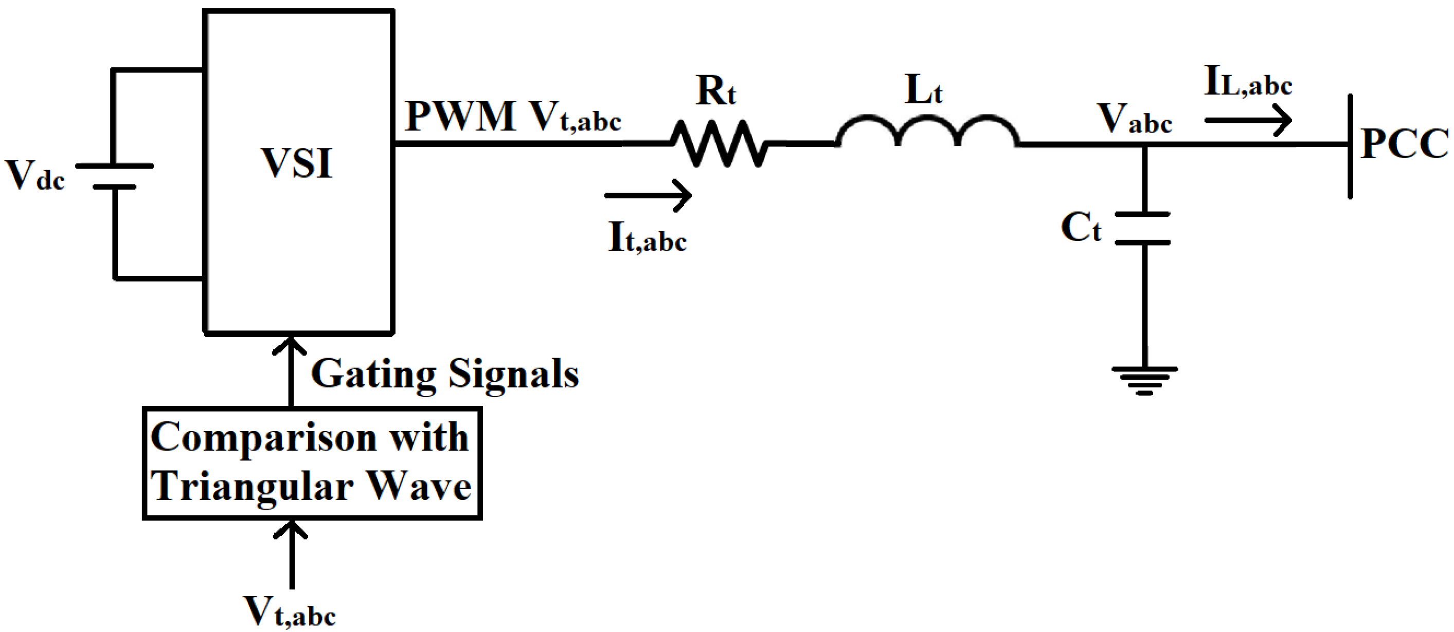
Figure 2.
Microgrid in Master/Slave Configuration.

Figure 3.
Control design for the slave VSIs working in power control mode (PCM).
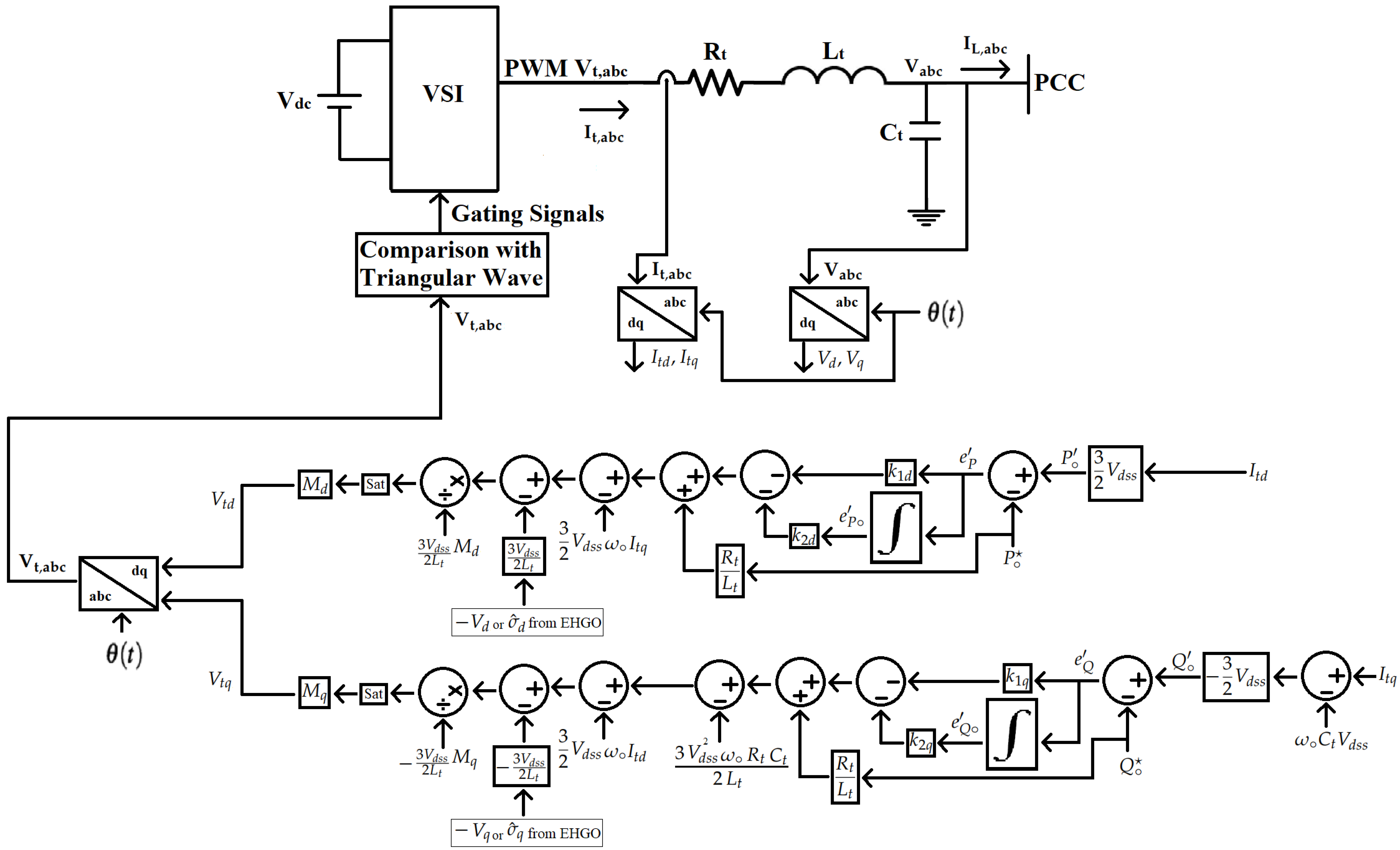
Figure 4.
Extended high gain observer (EHGO) design.

Figure 5.
Output voltages at the point of common coupling (PCC) in the reference frame.
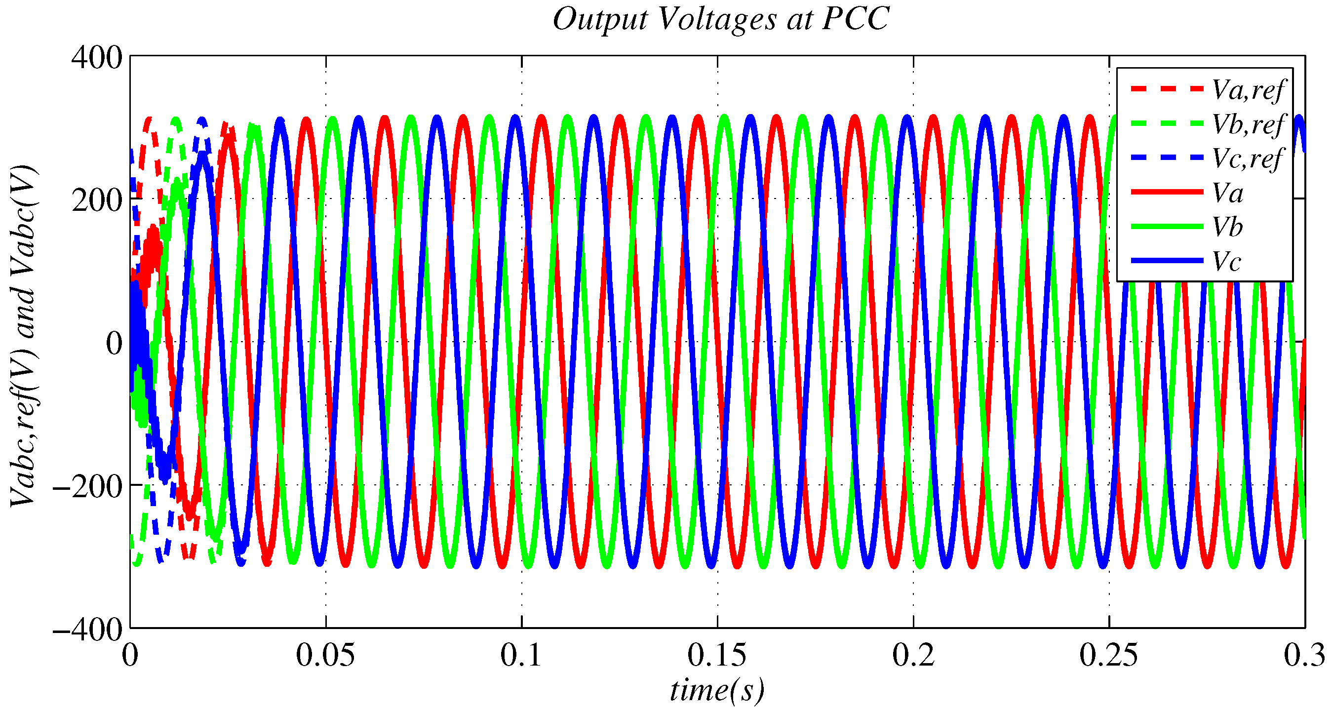
Figure 6.
Output current of the VSIs in the reference frame.

Figure 7.
Active power injected by the VSIs.

Figure 8.
Reactive power injected by the VSIs.
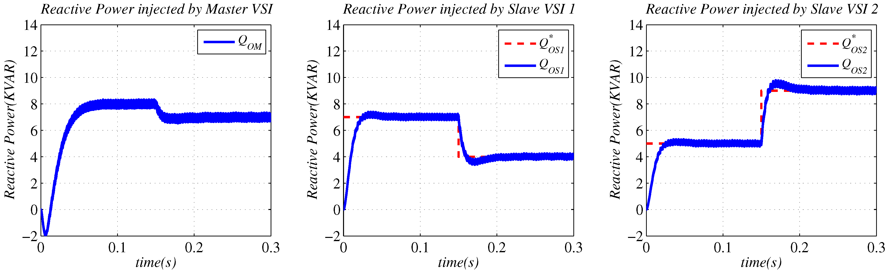
Figure 9.
Output voltages at the point of common coupling (PCC) in the reference frame (EHGO-based control).
Figure 9.
Output voltages at the point of common coupling (PCC) in the reference frame (EHGO-based control).

Figure 10.
Output current of the VSIs in the reference frame (EHGO-based control).

Figure 11.
Active power injected by the VSIs (EHGO-based control).

Figure 12.
Reactive power injected by the VSIs (EHGO-based control).
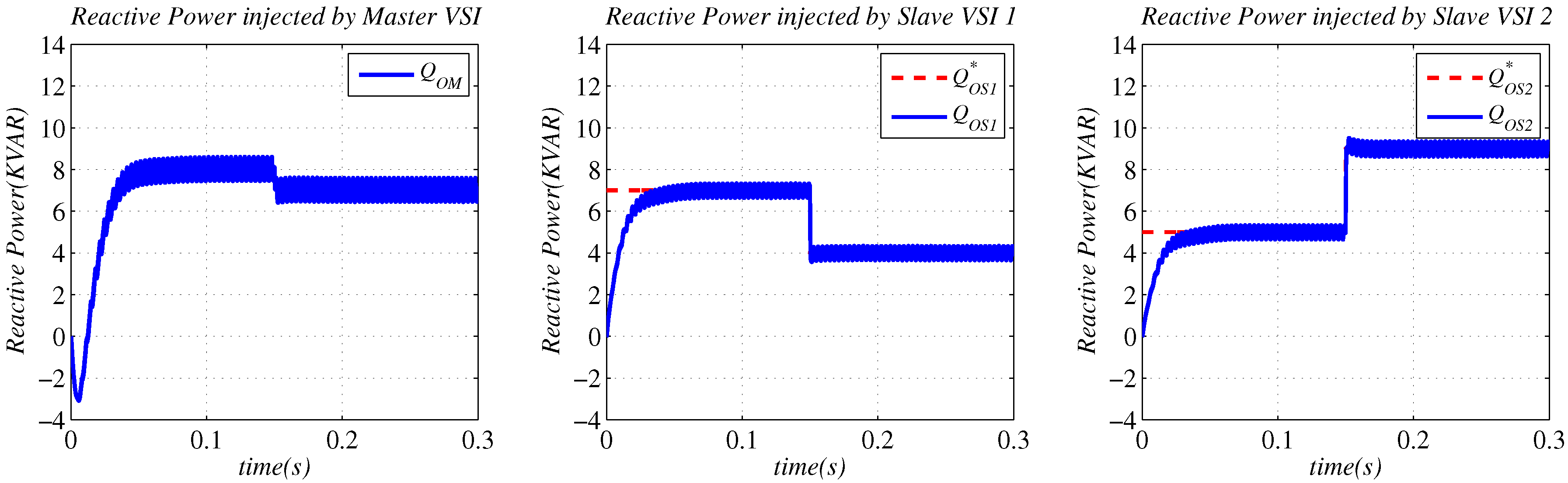
Figure 13.
Output current of the VSIs in the reference frame in case of sudden load change (non-EHGO-based control).
Figure 13.
Output current of the VSIs in the reference frame in case of sudden load change (non-EHGO-based control).

Figure 14.
Active power and reactive power injected by the VSIs, and drained by the load in case of sudden load change (non-EHGO-based control).
Figure 14.
Active power and reactive power injected by the VSIs, and drained by the load in case of sudden load change (non-EHGO-based control).

Figure 15.
Output current of the VSIs in the reference frame in case of sudden load change (EHGO-based control).
Figure 15.
Output current of the VSIs in the reference frame in case of sudden load change (EHGO-based control).

Figure 16.
Active power and reactive power injected by the VSIs, and drained by the load in case of sudden load change (EHGO-based control).
Figure 16.
Active power and reactive power injected by the VSIs, and drained by the load in case of sudden load change (EHGO-based control).

Figure 17.
PI-based control scheme for the slave VSIs working in power control mode (PCM).
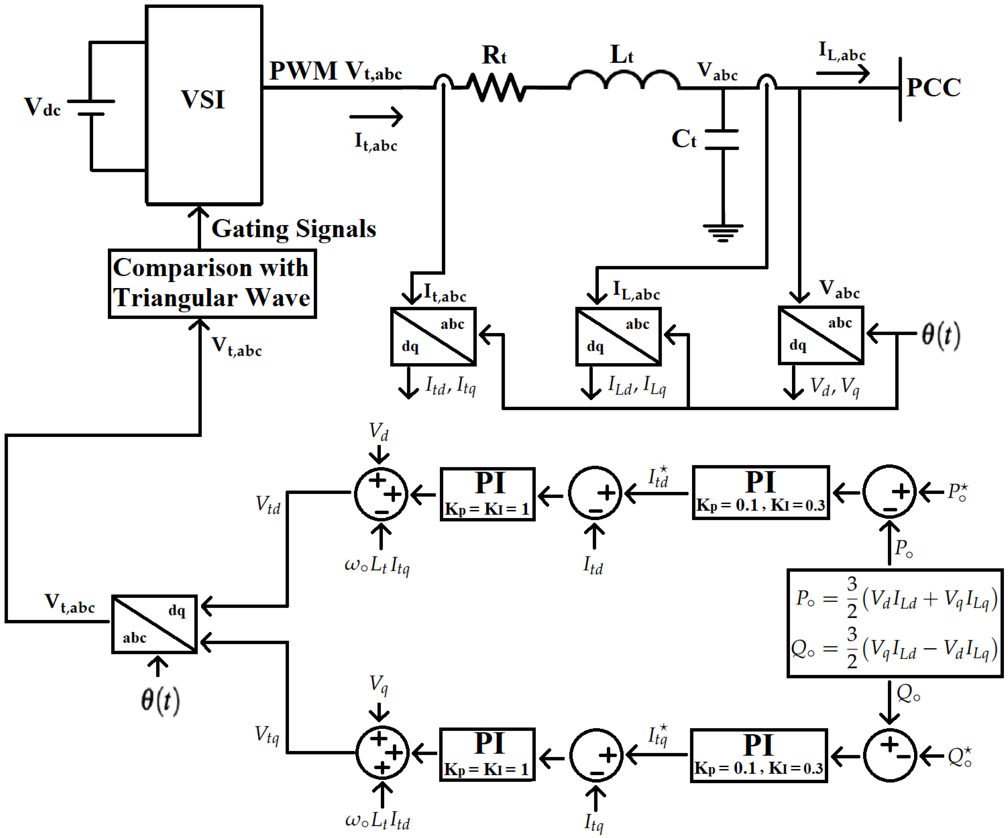
Figure 18.
Active power injected by the slave VSIs (comparison of the proposed control designs and PI controls).
Figure 18.
Active power injected by the slave VSIs (comparison of the proposed control designs and PI controls).

Figure 19.
Reactive power injected by the slave VSIs (comparison of the proposed control designs and PI controls).
Figure 19.
Reactive power injected by the slave VSIs (comparison of the proposed control designs and PI controls).


Table 1.
Electrical parameters of the microgrid.
| Electrical Parameters | Values |
|---|---|
| DC voltage source () | 1000 V |
| PWM carrier frequency | 12.8 KHz |
| Nominal voltage of the system (phase-to-neutral) | |
| Nominal frequency of the system | rad/s |
| Resistance of the VSI output filter | 0.2 |
| Inductance of the VSI output filter | 1 mH |
| Capacitance of the VSI output filter | 20 |
Table 2.
Required Power Sharing.
| Required Power Sharing | Values |
|---|---|
| Active power of the Load () | 20 KW |
| Reactive power of the Load () | 20 KVAR |
| Active power of the Slave VSI 1 () | 7 KW ( s), 4 KW ( s) |
| Reactive power of the Slave VSI 1 () | 7 KVAR ( s), 4 KVAR ( s) |
| Active power of the Slave VSI 2 () | 5 KW ( s), 9 KW ( s) |
| Reactive power of the Slave VSI 2 () | 5 KVAR ( s), 9 KVAR ( s) |
| Active power of the Master VSI () | |
| Reactive power of the Master VSI () |
Table 3.
Controller and EHGO parameters of the Slave VSIs.
| Parameters | Values |
|---|---|
| and | 0 |
| and | 10,000 |
| 500 | |
| 250 | |
| and | 2 |
| and |
Disclaimer/Publisher’s Note: The statements, opinions and data contained in all publications are solely those of the individual author(s) and contributor(s) and not of MDPI and/or the editor(s). MDPI and/or the editor(s) disclaim responsibility for any injury to people or property resulting from any ideas, methods, instructions or products referred to in the content. |
© 2023 by the authors. Licensee MDPI, Basel, Switzerland. This article is an open access article distributed under the terms and conditions of the Creative Commons Attribution (CC BY) license (https://creativecommons.org/licenses/by/4.0/).
Share and Cite
MDPI and ACS Style
Khan, H.S.; Memon, A.Y. Active and Reactive Power Control of the Voltage Source Inverter in an AC Microgrid. Sustainability 2023, 15, 1621. https://doi.org/10.3390/su15021621
AMA Style
Khan HS, Memon AY. Active and Reactive Power Control of the Voltage Source Inverter in an AC Microgrid. Sustainability. 2023; 15(2):1621. https://doi.org/10.3390/su15021621
Chicago/Turabian StyleKhan, Hamid Saeed, and Attaullah Y. Memon. 2023. "Active and Reactive Power Control of the Voltage Source Inverter in an AC Microgrid" Sustainability 15, no. 2: 1621. https://doi.org/10.3390/su15021621
Note that from the first issue of 2016, this journal uses article numbers instead of page numbers. See further details here.