
Numerical Investigation on Potential Influencing Factors Affecting Drainage Effective Radius of Crossing Borehole

1
Faculty of Safety Engineering, China University of Mining and Technology, Xuzhou 221116, China
2
China Pingmei Shenma Group, Pingdingshan 467000, China
3
College of Safety and Emergency Management Engineering, Taiyuan University of Technology, Taiyuan 030024, China
*
Authors to whom correspondence should be addressed.
Sustainability 2023, 15(3), 2485; https://doi.org/10.3390/su15032485
Submission received: 28 November 2022
/
Revised: 10 January 2023
/
Accepted: 19 January 2023
/
Published: 30 January 2023
(This article belongs to the Special Issue Prevention and Control of Coal Mine Gas Disasters)
Abstract
:Crossing borehole is an effective means to eliminate the outburst risk of coal and gas. The influence of borehole inclination angle, borehole diameter, and drainage time on the effective radius of gas drainage are studied by numerical simulation and engineering example verification. The study shows that the effective radius changes in a “U” shape with the increase in borehole inclination angle. When the angle α of the borehole and coal seam plane decreases, the effective radius increases. Furthermore, the coal mass around the borehole is broken by shear deformation, which is consistent with the results of the inner peephole. The effective radiuses are different in coal seam dip X and strike Y. When α is small, the effective radius in the X direction is generally wider. When α is large (α ≤ 90°), the effective radiuses in the X and Y directions are close. The effective radius is positively correlated with the borehole diameter and is more significantly influenced by increasing borehole diameter when α is small. The effective radius increases as a negative exponential function with time and eventually converges to a constant. The study has practical implications for the design of crossing borehole in the coal seam floor.
1. Introduction
As the depth of the coal mine increases, the conditions for gas deposition become complex [1]. Because the deep rock mass bears the greater vertical stress caused by the self-weight of the overlying strata and the tectonic stress caused by the geological structure, the higher ground stress is eventually formed, thus, aggravating the outburst risk of coal and gas [2]. Crossing borehole is a widely used technique in coal mine gas pre-drainage, neighboring layers, and gas management in mining areas, especially in strip pre-drainage of coal mine tunnels. Therefore, the discussion concerning the change law of effective drainage area under different characteristic parameters is of practical significance for preventing and controlling coal mine gas disasters and strengthening gas drainage [3].
The crossing borehole technique has been widely applied in the field practice, which eliminates the risk of coal and gas outburst regionally in combination with the pressure relief gas drainage of the protected layer [4]. Based on the crossing borehole, many new techniques were put forward to improve the efficiency of gas drainage. The literature details the use of static blasting techniques to pre-split the coal seam, thereby increasing the permeability and enhancing the drainage of the crossing borehole [5]. In the literature, the secondary drainage technique of pressure relief gas from the bottom rock tunnel was researched, using the bottom rock tunnel to arrange the overlying coal seam to intercept the flow through the layer [6]. When constructing upward crossing boreholes in bottom-slab grid tunnels, high-pressure water to induce borehole blowout was used, forming several borehole blowouts in the range of the hole group, causing the stress redistribution of the coal body [7]. In the literature, a pump-less dual-pass mechanical cavitation bit for crossing borehole to improve borehole diameter and bit reliability was designed [8]. The technologies, such as gas drainage by a cluster of holes, hydraulic fracturing through seam boreholes [9], and water–gas two-phase fracturing of coal seams, are based on the arrangement of crossing boreholes [10], so the study of the impact parameters of seam boreholes is helpful for technique optimization.
The parameters influencing the gas drainage from boreholes through or along the layers are also research hotspots. In the literature, the interaction between boreholes was studied by simulation [11] and by the three-dimensional experimental method [12] to observe the degree of gas content or pressure drop at different borehole spacings and arrangement shapes and, finally, to obtain the optimal gas drainage scheme. The literature concluded that the difference in the gas drainage effect of the crossing borehole is mainly due to the variation in the inclination angle [13], which causes different degrees of ground stress in the borehole and, consequently, different degrees of damage to the coal body near the borehole. The influence of the relationship between coal seam inclination and borehole inclination angle on the amount of drilling chips from the perspective of borehole arrangement was analyzed [14]. The influence of different borehole inclination angles on the stability of coal was studied [15]. Researchers studied the influence of different parameters on gas drainage in bedding borehole drainage [16] and verified that the influence of drainage negative pressure change on effective gas drainage area and gas pressure was very weak. The shear deformation and strength characteristics of loess boreholes under the influence of normal stress and shear stress were studied [17], as well as the influence of instability and collapse of drainage holes in soft coal seam on gas drainage [18].
Based on the change in inclination angle of the crossing borehole, it is relatively rare to study the parameters affecting drainage effective radius, which exists in practical engineering and has practical significance. When the coal seam has a certain inclination angle, the laws of the residual gas pressure and effective radiuses in the dip and strike are different, and it cannot be regarded as a standard circle. Therefore, in the X and Y directions (dip and strike), this paper studies the influence of parameters such as borehole inclination angle, borehole diameter, and drainage time on gas drainage. Analysis and investigation parameters, such as effective radius and residual gas pressure, tested the effect of different design schemes of floor crossing borehole and verified the reliability of the simulation in practical engineering. The conclusions obtained in this paper, taking into account the specific conditions of the coal seam and the optimal parameters of the borehole arrangement, can lead to an efficient and economical gas drainage design solution.
2. Numerical Model
2.1. Fluid–Solid Coupling Model
For the fluid–solid coupling model of gas, the following assumptions are made: (1) the coal seam is a porous medium that is saturated by single-phase gas; (2) the gas seepage inside the coal seam is treated as an isothermal process; (3) the coal seam skeleton is elastic–plastic; (4) the coal seam is an isotropic homogenous body.
- (1)
- Gas seepage Equation
The seepage of gas within the coal seam is in accordance with the law of mass conservation:
where is the mass of gas per unit volume of coal body containing gas, kg/m3; is the gas density, kg/m3; is the Darcy seepage velocity of gas, m/s; is the source sink term, kg/(m3·s); is the time-variant, s.
Assume that the gas content in the coal seam satisfies the Langmuir Equation [16]:
where is gas pressure, MPa; is the standard atmospheric pressure, 1.013 × 10⁵Pa; ρc is the density of the coal body, kg/m3; , is the Langmuir constant, m3/t, MPa−1, respectively; is the porosity.
Gas is a compressible gas, and assuming it is an ideal gas:
where is the relative molecular mass of the gas, 16 g/mol; R is the ideal gas constant, 8.314 J/(mol·K); T is the absolute temperature, K.
Assuming that the gas moves linearly in the pore structure of the coal body under the pressure gradient, in accordance with Darcy’s law [19] and considering the effect of gas gravity:
where is the dynamic viscosity of the gas, Pa·s; is height, m; is the effective permeability of gas in the coal seam, m2; is the acceleration of gravity, m·s−2.
Bringing Equations (2)–(4) into Equation (1), we can obtain the continuity equation considering the gas seepage during adsorption and desorption (coal body density change is neglected):
- (2)
- Cross-coupling Equation
The porosity of the coal seam is related to the state of stress to which it is subjected, and the porosity is dynamically changing. The stress state directly affects what stage the coal seam is in, and the porosity of the coal seam under the elastic stage and the plastic stage is different when the coal seam containing gas is in the elastic deformation stage, porosity ratio is [20]:
where is the initial porosity; is the volume strain; is the amount of gas pressure change, ; is the bulk modulus of the coal skeleton, MPa: ; E is the modulus of elasticity of coal body, GPa; is the Poisson’s ratio of coal seam.
When the coal seam containing gas is in the plastic strain strengthening stage, the porosity is:
where is the porosity of the coal body when the load applied to it reaches its peak stress (MPa); is the stress intensity; is the yield stress.
In low permeability coal seams, gas seepage has a significant Klinkenberg effect. The relationship between gas pore pressure and effective permeability is [21]:
where is the absolute permeability, m2; is the Klinkenberg factor, Pa.
According to the seepage mechanics Kozeny–Carman equation, it can be deduced that the Equation is:
where is the initial permeability of the coal seam, m2.
The effect of porosity should be taken into account when calculating the Klinkenberg factor [22]:
Combining Equations (8) and (10), when the low permeability coal seam is in the elastic stage, its effective permeability dynamic evolution Equation is:
According to the definition of porosity and considering the skeleton volume deformation caused by the gas pressure change, the equation of porosity calculation for the elastic stage of gas-containing coal rocks is obtained. Furthermore, the equation for the dynamic evolution of effective permeability during the strengthening phase of plastic strain is derived [23]:
where is the permeability of the coal seam when it reaches peak stress.
- (3)
- Deformation control Equation
The coal seam containing gas is in stress equilibrium before drilling, and the mechanical equilibrium equation is obtained from the law of conservation of momentum, as follows:
where is the stress tensor, Pa; for volumetric forces, Pa.
According to the characteristics of deformation continuity, the geometric equation of gas-containing coal seam is obtained as:
where is the strain component; and and is the displacement component.
The coal seam skeleton is elastic–plastic, so the stress–strain relationship of the coal body needs to be treated as a nonlinear material. The principal equation of the deformation field adopts the elastic–plastic principal equation with incremental form as [21]:
where is the effective stress tensor of gas-containing coal, Pa; is the elastic–plastic matrix.
The Drucker–Prager plastic yielding criterion is used for the coal body, which is:
where is the first invariant of effective stress; is the second invariant of the effective bias stress; , is the coal body constant; C is adhesive power, MPa; φ is the angle of internal friction, °.
The elastic–plastic matrix is expressed as:
where is the elasticity matrix, is the plasticity matrix.
2.2. Borehole Parameters
The modeling is based on the crossing borehole of the fourth gas control lane in the west wing of the twelfth mine of the Ping Coal Group. A group of crossing boreholes includes 18 boreholes with different design parameters. The control range of boreholes: 15 m outside the lower side contour of Hexa 15 Coal-31020 inlet lane to 64 m toward the mining face of Hexa 15 Coal-31020 inlet lane upper side, 79 m in total. Hole depth: the distance from the borehole opening to the borehole bottom 0.5 m above the coal seam roof. The design parameters of the hole are shown in Table 1. The arrangement of pre-drainage gas by the crossing borehole in the lower part of the Hexa 15 coal-31020 mining face is shown in Figure 1.
2.3. Model Parameters
The inclination angle of the coal seam is 15°, the size of the geometric model is 20 × 20 × 20 m, and the thickness of the coal seam is 4 m. To study the law of residual gas pressure and effective radius in dip and strike, an observation line is selected along X direction (coal seam dip) and Y direction (coal seam strike) in the center of the borehole.
When the boundary condition is set, the bottom boundary of the model is set as a fixed constraint, the surrounding boundary constrains the horizontal movement, the surrounding boundary loads the pressure of 6 MPa, and the upper boundary reloads the pressure of 10 MPa according to the overlying rock. The initial gas pressure of the coal seam is 2.0 MPa, the boundary around the coal seam is set as the initial gas pressure value, and the negative pressure of the borehole is set to 15 kPa. The physical parameters of the coal and rock seams are shown in Table 2.
3. Results and Discussion
3.1. Simulating the Effect of Borehole Inclination and Engineering Practice
After 90 days of pre-drainage, residual gas pressure distribution of the coal body around the drainage borehole under 6 inclination angles θ is shown in Figure 2. The drainage time is the same, but the effective area of gas drainage still has an obvious difference. When the angle α between the borehole and the coal seam plane is smaller (such as θ = 19° and 146°), the area of gas pressure drop is wider. When the angle between the two is larger (the borehole is nearly perpendicular to the coal seam), the area where the gas pressure drops is narrower. The area in the coal seam where the residual gas pressure is lower than 0.74 MPa is judged to be effective drainage. Figure 3 shows the profile of the effective drainage area. When the angle α is small, the effective area for gas drainage is larger in the cross-section of the coal seam.
There are differences in the effective radius of different borehole inclination angles (θ), as in Figure 4: The angles α between the middle boreholes and the coal seam plane are larger, and the angles between the boreholes and the vertical component of the ground stress on the coal seam plane are smaller, so it is less damaged by the vertical ground stress. However, when α is smaller, the area of the borehole subject to vertical ground stress is larger. At this moment, the coal body around the borehole is prone to shear deformation, and the degree of fragmentation increases, and then the permeability increases, so it helps to improve the drainage efficiency. Combined with Figure 2 and 3, when α is small, the effect of gas drainage is better.
As shown in Figure 5, the fitted curves of the drainage effective radius in X (dip direction) and Y (strike direction) both show a “U” shaped trend of high at both ends and low in the middle, but the curvature of X curve is obviously stronger than that of Y. When the borehole inclination is perpendicular to the coal seam plane, the drainage effective radii of X and Y are similar, and the change of effective radius per unit distance is small. In general, the change in borehole inclination will have a significant effect on gas drainage through the crossing borehole, and the effect is greater in the direction of coal seam inclination.
Figure 6 shows the results of six inner peeping holes under different borehole inclination angles. At θ = 74° and 87°, the coal body around the boreholes was less fragmented and only a small number of fractures were produced. When θ = 19° and 146°, the coal body around the boreholes appeared as a cross-section of layers (shear surface), which is the cause of shear stress action and generates a large number of fractures. When θ = 50° and 61°, the internal fractures of the borehole were at an intermediate level. Therefore, the results and thesis of Figure 4 are consistent with the actual engineering. The fragmentation of the coal body around the boreholes causes the fracture development and the permeability increases, which is favorable to gas drainage. The drainage effective radius is also increased accordingly, which is consistent with the simulation results.
3.2. Effect of Borehole Diameter under Different Drilling Inclination
The laws of drainage effective radius are studied for the same coal seam inclination and borehole diameters of Φ = 63 mm, 94 mm, and 125 mm, respectively. The laws of residual gas pressure in X and Y directions for different borehole diameters at several typical borehole inclination angles are shown in Figure 7. The residual gas pressure increases exponentially as a function of distance, i.e., P = P0 − P1e−x/β, where P is the residual gas pressure, P0 and P1 are fitting constants, x is the distance from the borehole center, and β is the residual gas pressure decay coefficient. As the borehole diameter increases, the residual gas pressure decay coefficient β values of X and Y both increase. The residual gas pressure decreases with increasing borehole diameter, which corresponds to the algorithm of residual gas pressure decay coefficient β, but α is smaller (θ = 19°, 119°), and the residual gas pressure is lower than the pressure at other borehole inclination angles. The gas pressure distribution characteristics in X and Y directions are similar and positively correlated, and in general, the residual gas pressure distribution characteristics are similar for different borehole diameters.
The drainage effective radius under different borehole diameters is given in Figure 8. At the same borehole inclination angle, the effective radii in both X and Y directions increase with the increase in borehole diameter, and the change characteristics of the fitted curves of effective radius under three different borehole diameters are similar. For example, when θ = 19° and the borehole diameter is 63 mm, the widths of drainage effective area in X and Y directions are 1.84 m and 0.96 m, respectively; when the borehole diameter is 94 mm, the values are 2.22 m and 1.16 m, respectively; when the borehole diameter is 125 mm, the values are 2.60 m and 1.35 m, respectively.
As shown in Figure 8a,b, when the borehole direction is close to the vertical ground stress (α is larger), the value of the drainage effective radius in the X direction is close to Y. At this time, increasing the borehole diameter, the effective radius increment is small and expanding the diameter of the borehole has little effect on drainage. So if α is larger, small diameter boreholes can be taken. When α is small, the borehole is subject to vertical ground stress, and expanding the borehole diameter can significantly increase the effective radius. Therefore, when the inclination of the borehole varies, a suitable borehole diameter can be used to achieve economic and effective gas drainage.
3.3. Spatial and Temporal Evolutionary Characteristics of the Drainage Effective Radius
The effect of pre-drainage time on the drainage effective radius was studied, with data recorded at 10-d intervals from 0 to 90 days. Borehole inclination angles were set to 50°, 61°, 87°, and 119°. As shown in Figure 9, with the borehole as the center of the circle, the observation radius is 10 m. The gas pressure curves show similar decreasing changes with increasing time gradient of 10 d. However, the gas pressure reduction decreases with time, and the gas pressure curves after t = 50 d are very similar. The results of the field test based on the flow rate of the borehole in the literature [24] show that the drainage effective radius tends to level off after a certain moment. The results of this paper are consistent with the above phenomenon.
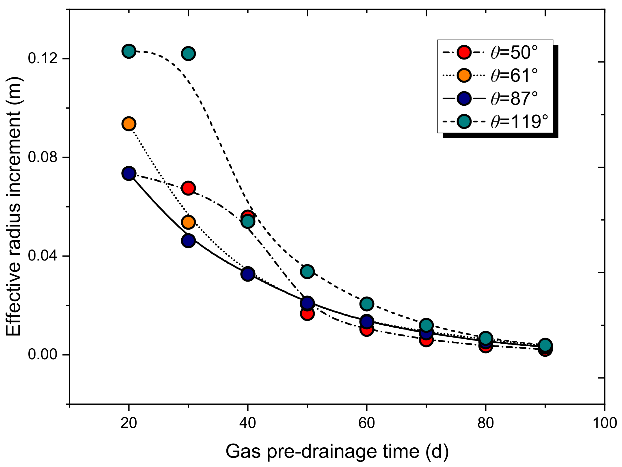
As shown in Figure 10, the drainage effective radius increases with time. Figure 11 plots the variation of the increase in the drainage effective radius (increment over the previous node) at different time nodes. The increment fluctuates at θ = 119° and t = 30 h, but overall, the increment of effective radius at the previous time node is greater than that at the latter one. The increment of effective radius tends to 0.0038 with increasing pre-drainage time and no longer shows significant fluctuations. After t = 80 d, the increment of effective radius hardly changes and it is close to 0. There exists a reasonable range of pre-drainage time for the borehole, when below the lower boundary of time, the gas pressure does not drop below 0.74 MPa. When exceeding the upper boundary, the economic efficiency of drainage is low. In practical engineering, it is important to determine the reasonable pre-drainage time of the borehole for the alternate work of mining and excavation the coal seam.
4. Conclusions
To investigate the influence of the design parameters of the crossing borehole on the gas drainage radius, this paper studies the influence of borehole inclination angle, borehole diameter, and pre-drainage time on the drainage effective radius. The results of the simulations are mutually verifiable and have been validated in engineering practice, with the following conclusions:
- (1)
- Borehole inclination angle has a significant influence on the drainage effective radius. When the angle α between the borehole and the coal seam plane is small, The vertical component of the ground stress on the coal seam plane has a larger area of action on the boreholes. It is easy to produce shear deformation in the coal body around the boreholes and the degree of fragmentation increases. At this time, the permeability of the coal body near this borehole increases and the drainage effective radius increases.
- (2)
- The drainage effective radii are different in the dip and strike directions of the seam (X and Y directions). When α is smaller, the drainage effective radius in the dip direction is usually wider. When α is larger (maximum when vertical), the effective radii in the dip and strike directions are nearly equal.
- (3)
- In general, the drainage effective radius increases with the increase in borehole diameter, but there are differences in the effective radius increment at different borehole inclination angles. When α is larger, the borehole diameter increases but the effective radius increment is small, and the influence of borehole diameter on gas drainage is small at this time. When α is smaller, expanding the borehole diameter can significantly increase the effective radius.
- (4)
- The drainage effective radius increases with time, and the fitted curve has a negative exponential relationship and gradually slows down and converges to a certain value. The increment of effective radius is less affected by time after t = 60 d, and the increment is close to 0 after t = 80 d. The residual gas pressure curve is very close after t = 50 d, so there is a reasonable interval of time for pre-drainage gas.
Author Contributions
Conceptualization, C.Z. and Z.L.; methodology, C.Z.; validation, W.X., Z.L. and M.S.; formal analysis, W.X.; investigation, W.X.; resources, W.X.; data curation, K.L.; writing—original draft preparation, K.L.; writing—review and editing, K.L.; visualization, C.M.; supervision, B.L.; project administration, B.L.; funding acquisition, C.Z. All authors have read and agreed to the published version of the manuscript.
Funding
Financial support provided by the National Natural Science Foundation of China (52174211, 52004176) and National Science and Technology Major Project (2020YFA0711803) for this research is gratefully acknowledged.
Institutional Review Board Statement
Not applicable.
Informed Consent Statement
Not applicable.
Data Availability Statement
The data that supports the findings of this study is available from the corresponding author upon reasonable request.
Conflicts of Interest
The authors declare no conflict of interest.
References
- Zou, J.; Zhang, R.; Zhou, F.; Zhang, X. Hazardous Area Reconstruction and Law Analysis of Coal Spontaneous Combustion and Gas Coupling Disasters in Goaf Based on DEM-CFD. ACS Omega 2023, 8, 2685–2697. [Google Scholar] [CrossRef] [PubMed]
- Yuan, L. Research progress of mining response and disaster prevention and control in deep coal mines. J. China Coal Soc. 2021, 46, 716–725. [Google Scholar] [CrossRef]
- Lin, B.; Song, H.; Yang, W.; Zhao, Y.; Cha, W. Study on effective gas drainage area based on anisotropic coal seam. Coal Sci. Technol. 2019, 47, 139–145. [Google Scholar] [CrossRef]
- Cheng, Y.; Yu, Q. Development of Regional Gas Control T echnology for Chinese Coalmines. J. Min. Saf. Eng. 2007, 4, 383–390. [Google Scholar]
- Zhang, X.; Zhou, F.; Zou, J. Numerical Simulation of Gas Extraction in Coal Seam Strengthened by Static Blasting. Sustainability 2022, 14, 12484. [Google Scholar] [CrossRef]
- Li, Y.; Zhai, C.; Ding, X. Technology and application of dynamic pressure gas secondary drainage through borehole in bottom drainage roadway of high gas outburst coal seam. Saf. Coal Mines 2022, 53, 191–196. [Google Scholar] [CrossRef]
- Zhou, H.; Cheng, Y.; Liu, H.; Guo, P.; Wang, L. Permeability improvement technology of array crossing boreholes and its application in outburst coal seam. J. China Coal Soc. 2011, 36, 1515–1518. [Google Scholar] [CrossRef]
- Gao, X.; Shao, G.; Yang, H. Design and application of pump-free double channel mechanical hole enlarging bit for gas penetration in middle hard coal seam. Coal Geol. Explor. 2022, 50, 159–164. [Google Scholar]
- Yuan, Z.; Wang, H.; Hu, G.; Fan, X.; Liu, N. Numerical simulation of hydraulic fracturing of crossing borehole and its engineering application. J. China Coal Soc. 2012, 37, 109–114. [Google Scholar] [CrossRef]
- Li, K.; Zhu, C.; Liu, S.; Chen, D.; Cai, G. Effects of Injection Pressure and Duration on Alternate High-Pressure Water-Gas Sequestration of Coalbed Methane. Geofluids 2022, 2022, 1–15. [Google Scholar] [CrossRef]
- Liu, Z.; Cheng, Y.; Jiang, J.; Li, W.; Jin, K. Interactions between coal seam gas drainage boreholes and the impact of such on the borehole patterns. J. Nat. Gas Sci. Eng. 2017, 38, 597–607. [Google Scholar] [CrossRef] [Green Version]
- Jia, L.; Peng, S.; Xu, J.; Yan, F.; Chen, J.; Wu, B. Investigation on gas drainage effect under different borehole layout via 3D monitoring of gas pressure. J. Nat. Gas Sci. Eng. 2022, 101, 104522. [Google Scholar] [CrossRef]
- Lyo, Y.; Zhu, C. Study on attenuation law of gas drainage flow in borehole passed through seam with different inclined floor. Coal Sci. Technol. 2017, 45, 74–79. [Google Scholar] [CrossRef]
- Zhou, Y.; Liang, B.; Shi, Z.; Sun, W.; Liu, X. Theoretical study on the drilling cuttings considering coal seam angle and borehole angle. Min. Saf. Environ. Prot. 2020, 47, 26–30,35. [Google Scholar] [CrossRef]
- Lin, H.; Liu, S.; Li, S.; Shuang, H.; Kong, X.; Chen, C.; Xiao, P.; Xu, P. Experimental study for the effects of drilling angle on coal mass stability under stable pressure conditions. J. Min. Saf. Eng. 2021, 38, 575–583. [Google Scholar] [CrossRef]
- Wang, Y.; Yang, L.; Fan, C. Effective drainage area and parameter optimization of bedding drilling in high gas and thick coal seam. Saf. Coal Mines 2022, 53, 212–221. [Google Scholar] [CrossRef]
- Yu, Y.; Zhu, J.; Zheng, J.; Huang, X.; Zhang, L.; Zhang, J. Study on Deformation and Strength Characteristics of Xi’an Loess by Borehole Shear Tests. J. Disaster Prev. Mitig. Eng. 2022, 42, 1104–1112,1120. [Google Scholar] [CrossRef]
- Zhang, X.; Wang, H.; Yang, M.; Wang, P. Study and application on influence mechanism of instability and collapse of drainage borehole on gas drainage. J. China Coal Soc. 2022, 1–15. [Google Scholar] [CrossRef]
- Yang, T.; Chen, S.; Zhu, W.; Liu, H. Coupled model of gas flow-solid distortion in coal seams based on dynamic process of pressure relief and gas drainage. Rock Soil Mech. 2010, 2247–2252. [Google Scholar] [CrossRef]
- Li, S.; Jiang, C.; Yao, J.; Li, M. Solid-gas coupling model and numerical simulation of coal containing gas based on comsol multiphysic. In Proceedings of the 8th National Conference on Rock Mechanics and Engineering Experimentation and Testing Technology, Changchun, China, 8–10 August 2012; pp. 446–451. Available online: https://d.wanfangdata.com.cn/conference/ChZDb25mZXJlbmNlTmV3UzIwMjIxMDEyEgc3OTc5MDYxGghwbTloOGI5cQ%3D%3D (accessed on 30 October 2022).
- Lu, Y.; Jia, Y.; Ge, Z.; Xia, B. Coupled fluid-solid model of coal bed methane and its application after slotting by high-pressure water jet. J. China Univ. Min. Technol. 2014, 43, 23–29. [Google Scholar] [CrossRef]
- Zhu, Y.; Tao, G.; Fang, W.; Wang, S. Research progress of the klinkenberg effect in tight gas reservoir. Prog. Geophys. 2007, 5, 1591–1596. [Google Scholar]
- Yin, G.; Li, M.; Li, S.; Li, W.; Yao, J.; Zhang, Q. 3D numerical simulation of gas drainage from boreholes based on solid gas coupling model of coal containing gas. J. China Coal Soc. 2013, 38, 535–541. [Google Scholar] [CrossRef]
- Mitra, A.; Harpalani, S.; Liu, S. Laboratory measurement and modeling of coal permeability with continued methane production: Part 1—Laboratory results. Fuel 2012, 94, 110–116. [Google Scholar] [CrossRef]
Figure 1.
Schematic layout of pre-drainage gas in the crossing borehole.

Figure 2.
Residual gas pressure distribution at different borehole inclination angles.
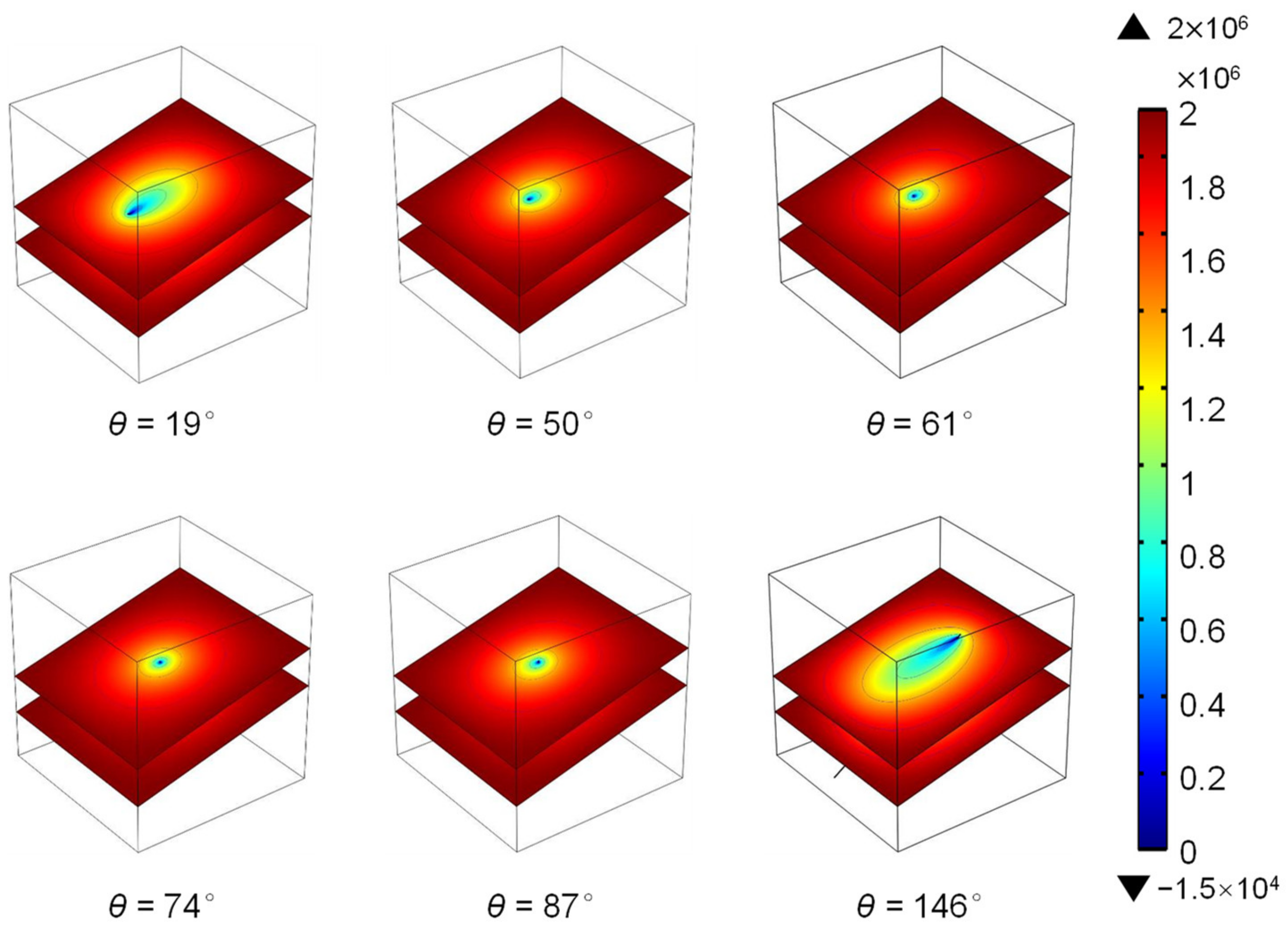
Figure 3.
Profile of the drainage effective area.
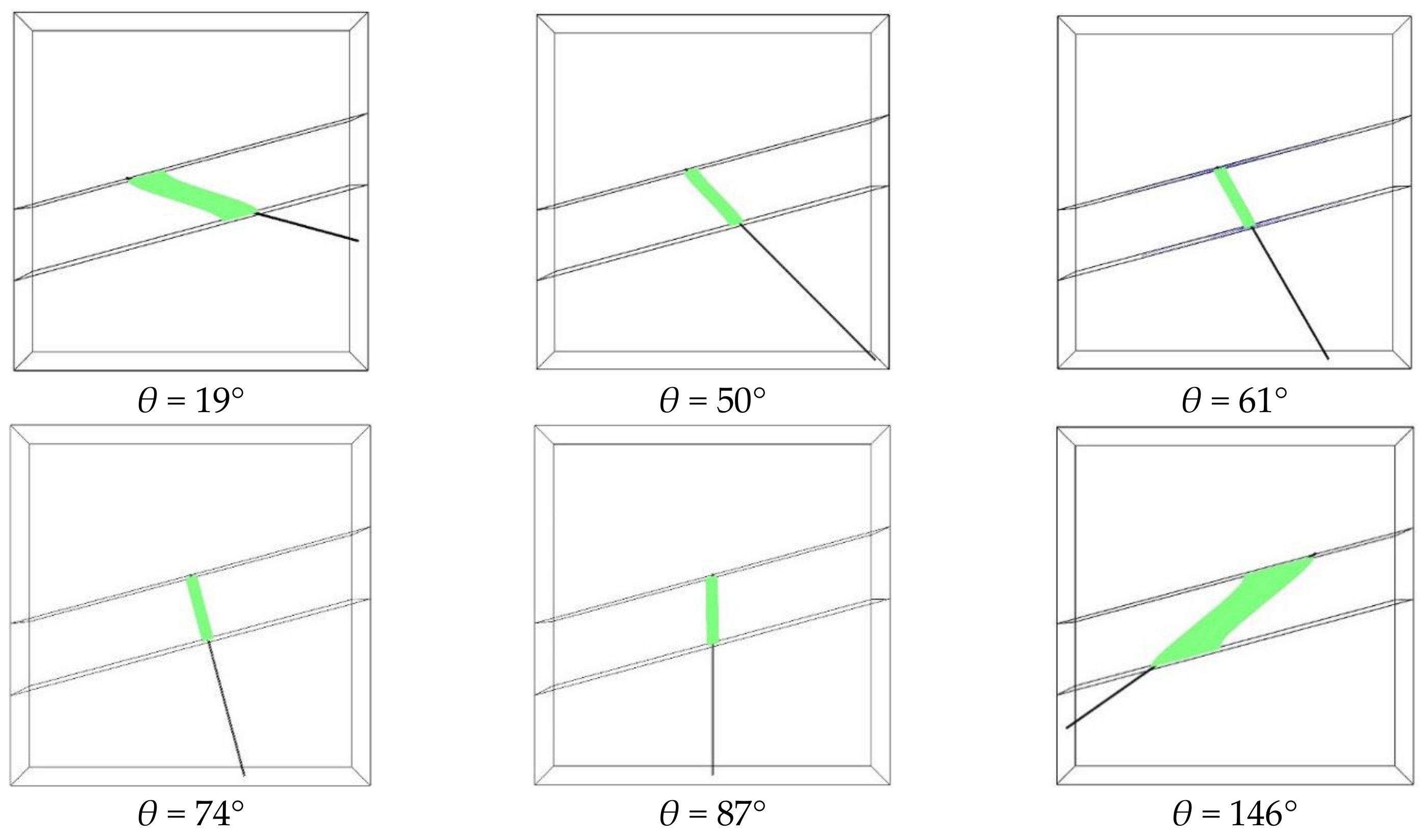
Figure 4.
Effective radius varies with the borehole inclination angles.

Figure 5.
Comparison of drainage effective radiuses in X and Y directions.

Figure 6.
Peephole fracture development in holes with different inclination angles θ.

Figure 7.
Variation of residual gas pressure with distance under different borehole diameters.
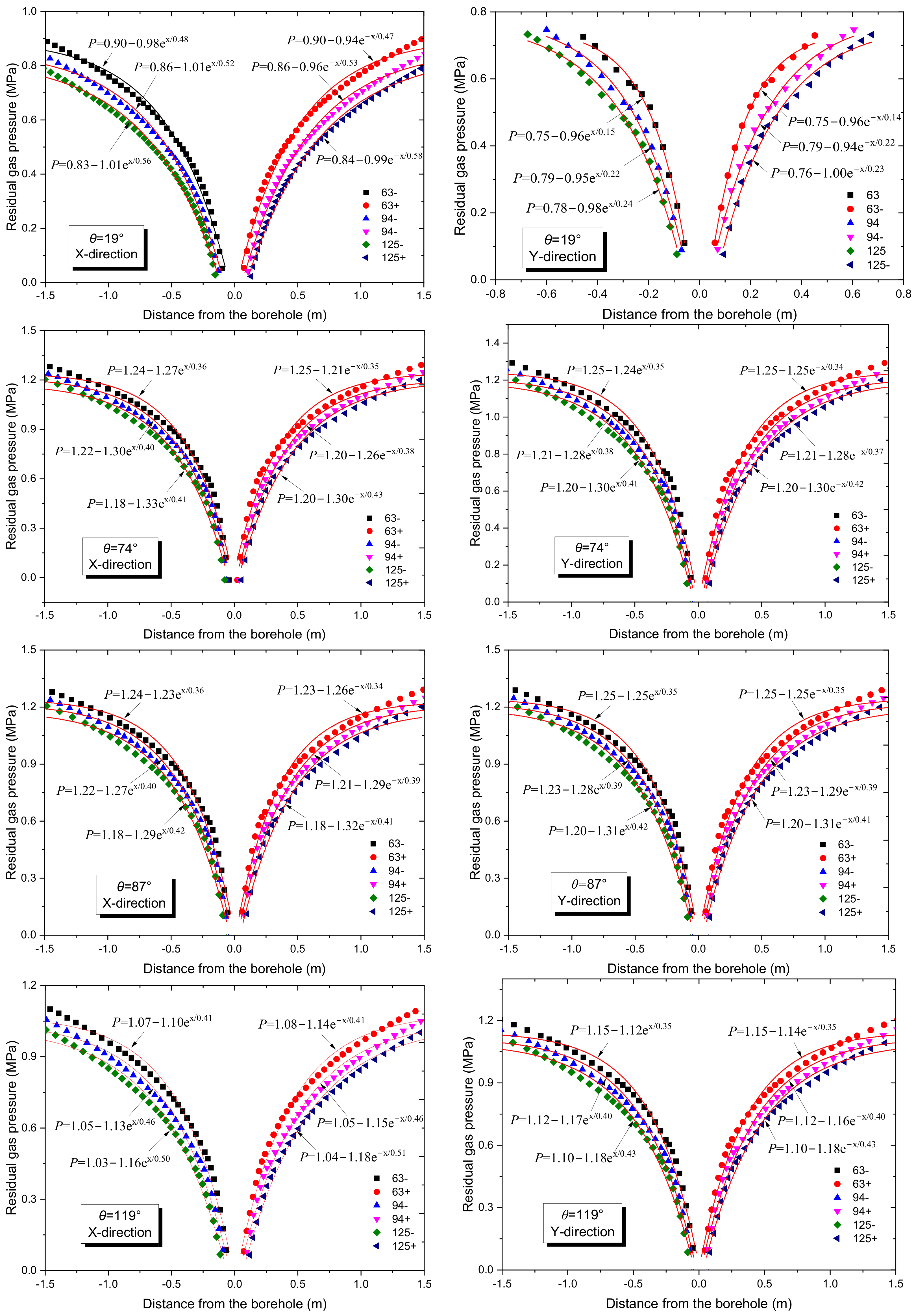
Figure 8.
Drainage effective radius under different borehole diameters in X and Y directions.
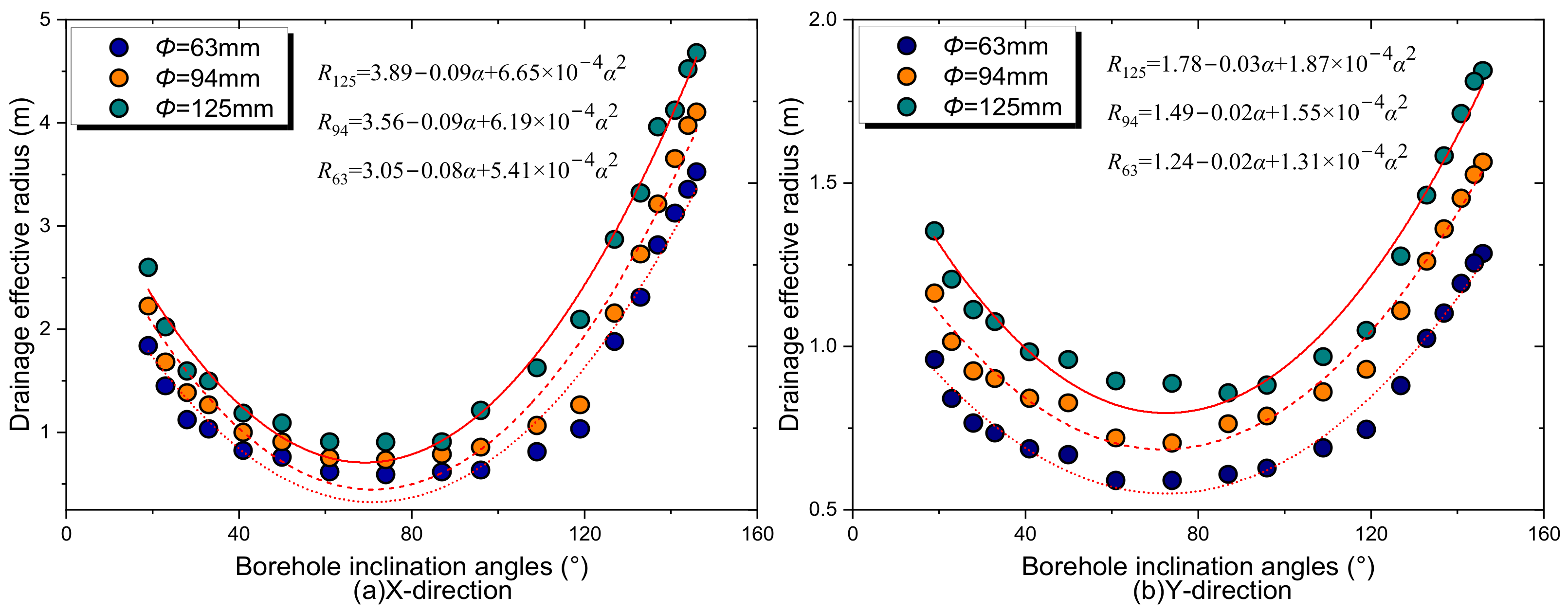
Figure 9.
Gas pressure with distance at different pre-drainage times.
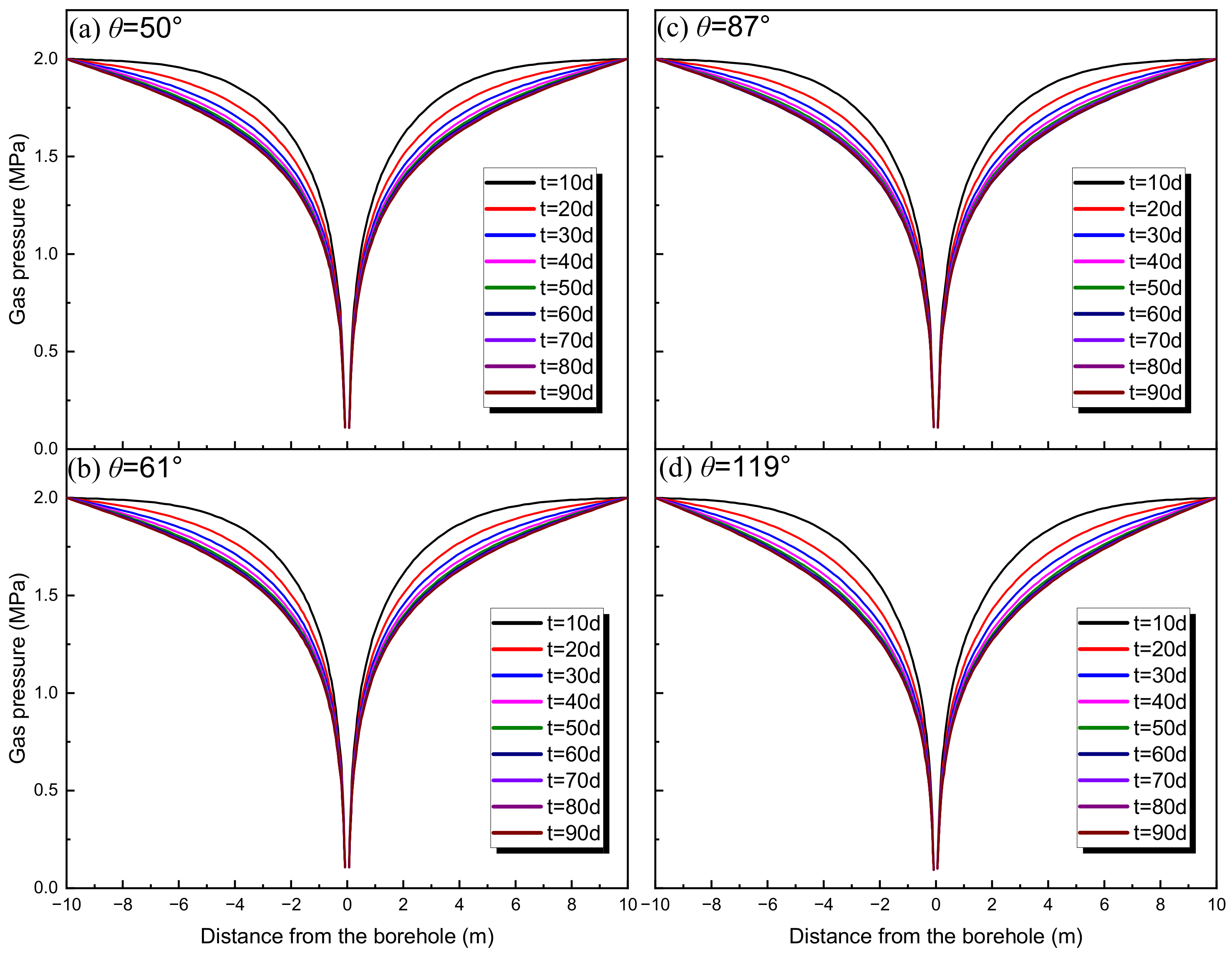
Figure 10.
Time-dependent effective radius at different borehole inclination angles.
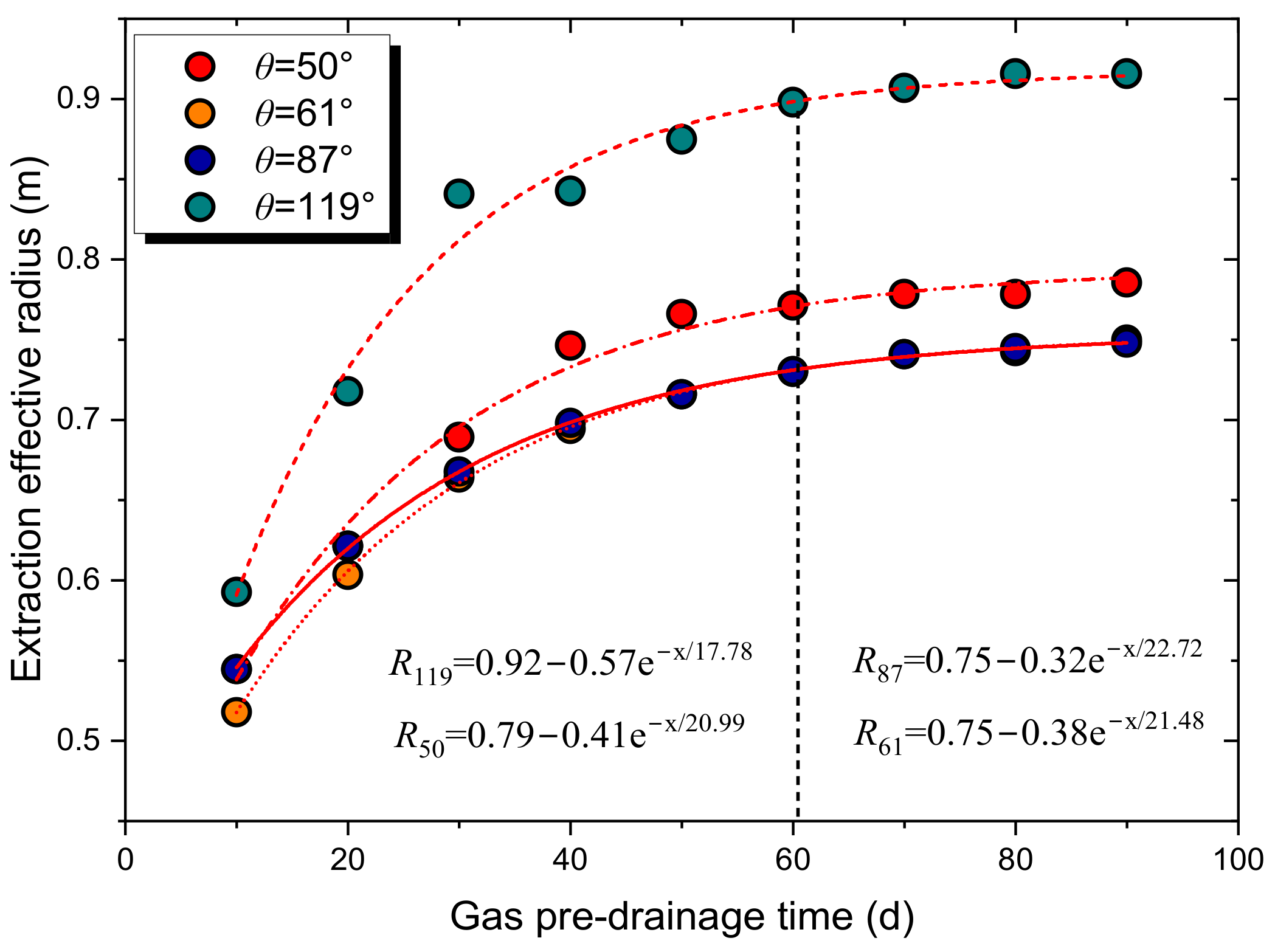
Figure 11.
Effective radius increment with time at different borehole inclination angles.

Table 1.
Borehole design parameters.
| Hole No. | Inclination Angle (°) | Diameter (mm) | Azimuth Angle (°) | Hole Depth (m) | Hole No. | Inclination Angle (°) | Diameter (mm) | Azimuth Angle (°) | Hole Depth (m) |
|---|---|---|---|---|---|---|---|---|---|
| 1 | 146 | 89 | 214.5 | 53 | 10 | 87 | 89 | 34.5 | 20 |
| 2 | 144 | 89 | 214.5 | 48 | 11 | 74 | 89 | 34.5 | 20 |
| 3 | 141 | 89 | 214.5 | 43 | 12 | 61 | 89 | 34.5 | 22 |
| 4 | 137 | 89 | 214.5 | 39 | 13 | 50 | 89 | 34.5 | 23 |
| 5 | 133 | 89 | 214.5 | 35 | 14 | 41 | 89 | 34.5 | 25 |
| 6 | 127 | 89 | 214.5 | 30 | 15 | 33 | 89 | 34.5 | 29 |
| 7 | 119 | 89 | 214.5 | 28 | 16 | 28 | 89 | 34.5 | 33 |
| 8 | 109 | 89 | 214.5 | 25 | 17 | 23 | 89 | 34.5 | 36 |
| 9 | 96 | 89 | 214.5 | 21 | 18 | 19 | 89 | 34.5 | 40 |
Table 2.
Model physical properties parameter values.
| Parameter and Unit | Parameter Value | Parameter and Unit | Parameter Value |
|---|---|---|---|
| Modulus of elasticity of coal body, E/(Pa) | 1.2 × 10⁹ | Friction angle of coal body, φ/(°) | 32 |
| Poisson’s ratio of coal body, υ | 0.2 | Rock Young’s modulus, E/(Pa) | 2.7 × 10¹⁰ |
| Initial penetration rate, k0/(m2) | 5 × 10⁻¹⁴ | Poisson’s ratio of rock layer, υ | 0.17 |
| Initial porosity, φ0 | 0.0604 | Rock density, ρyan/(kg/m3) | 2600 |
| Maximum penetration rate, km/(m2) | 4.5 × 10⁻¹³ | Adsorption constants, ag/(m3/kg) | 14.1 |
| Maximum porosity, φm | 0.0650 | Adsorption constants, bg/(1/MPa) | 0.77 |
| Density of coal body, ρc/(kg/m3) | 1500 | Gas power viscosity, μ/(Pa·s) | 1.84 × 10⁻⁵ |
| Cohesion of coal body, C/(Pa) | 3 × 10⁶ | Gas density, ρg/(kg/m3) | 0.717 |
Disclaimer/Publisher’s Note: The statements, opinions and data contained in all publications are solely those of the individual author(s) and contributor(s) and not of MDPI and/or the editor(s). MDPI and/or the editor(s) disclaim responsibility for any injury to people or property resulting from any ideas, methods, instructions or products referred to in the content. |
© 2023 by the authors. Licensee MDPI, Basel, Switzerland. This article is an open access article distributed under the terms and conditions of the Creative Commons Attribution (CC BY) license (https://creativecommons.org/licenses/by/4.0/).
Share and Cite
MDPI and ACS Style
Xiao, W.; Li, K.; Zhu, C.; Li, Z.; Lin, B.; Ma, C.; Si, M. Numerical Investigation on Potential Influencing Factors Affecting Drainage Effective Radius of Crossing Borehole. Sustainability 2023, 15, 2485. https://doi.org/10.3390/su15032485
AMA Style
Xiao W, Li K, Zhu C, Li Z, Lin B, Ma C, Si M. Numerical Investigation on Potential Influencing Factors Affecting Drainage Effective Radius of Crossing Borehole. Sustainability. 2023; 15(3):2485. https://doi.org/10.3390/su15032485
Chicago/Turabian StyleXiao, Wu, Ke Li, Chuanjie Zhu, Ziwen Li, Baiquan Lin, Cong Ma, and Mingkai Si. 2023. "Numerical Investigation on Potential Influencing Factors Affecting Drainage Effective Radius of Crossing Borehole" Sustainability 15, no. 3: 2485. https://doi.org/10.3390/su15032485
Note that from the first issue of 2016, this journal uses article numbers instead of page numbers. See further details here.