
The Floor Heave Mechanism and Control Technology of Gob-Side Entry Retaining of Soft Rock Floor
State Key Laboratory of Coal Resources and Safe Mining, School of Mines, China University of Mining and Technology, Xuzhou 221116, China
*
Author to whom correspondence should be addressed.
Sustainability 2023, 15(7), 6074; https://doi.org/10.3390/su15076074
Submission received: 23 February 2023
/
Revised: 26 March 2023
/
Accepted: 30 March 2023
/
Published: 31 March 2023
(This article belongs to the Collection Sustainable Development of Coal Based Energy: Technology, Environment, Humanities, Economy, and Education)
Abstract
:Extensive soft-rock floor heave in gob-side entry retaining considerably restricts the efficient and sustainable production of the mine. The mechanical capacities of roadway roof and floor strata are discussed through laboratory tests by taking the N2301 fully caving surface auxiliary transport gate road of the Ancient City Coal Mine in the Lu’an Mining Area of Shanxi Province as an engineering background. The stress distribution law of gob-side entry in mining the working surface was explored based on numerical simulation. After that, the mechanical mechanism of floor heave was studied through theoretical analysis. High lead abutment pressure and horizontal stress were superimposed in front of the working surface to cause soft-rock floor heave. The bulk weight of the high overburden was unevenly transmitted to the two sides because of the roof cantilever structure of entry retaining in the rear of the working face. The roadway floor produced an asymmetric sliding force, which caused the occurrence of floor heave. The control technology of floor heave combining the pressure relief of floor blasting and roof cutting was proposed taking account of the mechanism of floor heave. Then, the stress environment of the surrounding rock was improved by the deep hole blasting of the floor. Gob-side roof cutting was used to reduce impact of the bulk weight of the overburden on the surrounding rock deformation of the roadway. A test was conducted after verifying the control effect of blasting pressure relief on roadway floor heave through a similar simulation. Field tests indicated that the maximum floor heave was 168 mm at 250 m in the rear of the working surface, and floor heave was controlled. This study offers a more scientifically sound theoretical reference for controlling floor heave in gob-side entry retaining, which can significantly advance the sustainable development of gob-side entry retaining technology in coal mining.
1. Introduction
Roadway floor heave is always one of the urgent problems to be solved for safe mine production [1]. Thick seams have been widely exploited as the main coal seams for high-yield and efficient mining in China with the highly mechanized advancement of underground mining. The excavation roadways in thick seams are arranged along the roof for maintenance, which causes thickening of the bottom coal. Furthermore, to increase rational resource extraction and enhance the sustainability of coal mining, gob-side entry retaining technology is frequently implemented, which consequently leads to challenging floor maintenance. [2,3]. High-stress superposition in deep mines results in serious floor heave problems in mining roadways [4,5,6], which affects mine transportation and the efficient advancement of the working face [7,8,9,10]. An urgent need exists to propose a more rational and effective technology scheme for controlling floor heave in order to promote the sustainable development of gob-side entry retaining technology and resource mining in the coal mining industry.
The control scheme of floor heave mainly relies on reinforcement theory, pressure relief theory, and joint support theory. Reinforcement theory mainly focuses on anchor bolts, cable, and grouting reinforcement. Fan [11] proposed a control technical scheme based on reinforced support of floor bolts. Gao [12] put forward local control measures of floor grouting and reinforcement for the water-swelling and floor heave of squeeze fluidity. Yang [13] proposed the core support measures of “high-strength bolt-mesh beam cable, spray sealing, and floor anchoring” based on the control measures of intensified surrounding rock strength, enhanced floor stiffness, and weakened stratification effect. Zhang [14] analyzed the stress distribution and support strength of rock strata to propose the combined support technology of “anchor beam, anchor rod, net spray, and pouring concrete”. Yang [15] investigated the deformations of floor heave. The following surrounding rock control schemes are proposed based on the combined support plan of “coordinated the non-uniform deformation, controlled squeeze liquidity floor, and strengthened bearing structure of surrounding rocks”. Anchor cables are added to weak parts of roadways. The floor support strength is enlarged by channel steel beam truss anchor cables. In addition, concrete layers are timely injected to erect U-shaped steel for grouting full-section walls. Sun [16] proposed that floor heave is controlled through the treatment scheme of “roadway floor anchor cable bundle and floor depth grouting” according to similar simulation verification.
Pressure relief theory consists of roof-cutting pressure relief, floor slotting pressure relief, and deep hole blasting pressure relief. Lu [17] proposed a floor heave control scheme for drilling and relieving pressure to transfer the peak stress of the roadway side. Gao [18] put forward the control technology of floor heave of deep hole blasting and pressure relief under high stress. Zhang [19] controlled the bottom drum of the roadway by performing pre-cracking and pressure relief on the lateral roof of adjacent gob-side entry. Wang et al. [20] proposed a floor heave control method for reducing pressure in the arrangement of split-level roadways based on asymmetric floor heaves of gob-side entry. Zhai et al. [21] implemented a technical scheme for the floor pressure relief groove to solve the floor heave of the chamber in the high-stress zone of protected pillars. Floor heave is thus controlled.
Joint support theory combines pressure relief theory and reinforcement theory to jointly maintain the floor. Yu [22] proposed the integrated floor heave control technology of “pressure relief by roof cutting, flexible yielding, roof control by reinforced anchor cable, and side control by dual-control bolts”. Qin [23] compared the floor heave control schemes of pressure relief grooves, floor grouting reinforcement, and “floor pressure relief groove, watering concrete, and grouting pipe” based on numerical simulation. The floor heave of the roadway can be controlled by pressure relief combined with grouting reinforcement. Zhao [24] proposed floor heave control methods such as drilling pressure relief of the side floor of coal pillars and filling strengthening of the side floor of the goaf based on the stress and asymmetric deformation of surrounding rocks of floor on both roadway sides. Zhang [25] put forward the bolt support technology creating high stiffness, high strength, and a high anchoring point combined with deep groove pressure relief for the floor heave under high stress and weak structure. Jing [26] considered that a single support form cannot maintain the surrounding rock stability of deep roadways. Floor heave is controlled by the composite support method using side floor bolts combined with corner blasting pressure relief.
The above research provides the theory and method for treating floor heave. However, few studies focus on floor heave of gob-side entry driving along the roof of thick seams. The floor of such roadways is weak and prone to deformation. In addition, floor heave cannot be easily controlled because of the changed stress environment of gob-side entry. The floor heave characteristics of the working face are combined to study the floor heave of gob-side entry driving along the roof of thick seams. Therefore, a control scheme of floor heave is proposed to provide a reference for controlling the floor heaves of gob-side entry in soft-floor thick seams.
2. Background
The N2301 working face of the Ancient City Coal Mine in the Lu’an mining area is the first mining face of the northern mining area (see Figure 1). The working face is arranged in a north–south direction, with an advancing length of 1050 m. Coal seam #3 is mined, with an average inclination angle of 6° and an average thickness of 6 m. The auxiliary transportation roadway of the working face is in 3# coal seam and advanced along the roof of coal seams. No abnormal structure is found during the roadway excavation because of the stable occurrence of coal seams. The roadway is mainly used for air intake and auxiliary transportation of the N2301 working face, with an average burial depth of 500.42 m and no impact hazard. The east side of the roadway is parallel and adjacent to the high-pumping roadway of the working face; the west side is N2302 working face; the north side is West Wing roadway. Figure 1 shows the roadway layout. Gob-side entry retaining is used for auxiliary transportation roadway in mining the N2301 working face to achieve safe and efficient mining in high-gas mines and increase the resource recovery rate. Y-shaped ventilation is adopted. In other words, the N2301 working surface is used for air intake of transportation roadways and auxiliary transportation roadways. The retaining roadway is used for air return.
The auxiliary transportation roadway of the N2301 working face is rectangular, with a digging width of 5500 mm, a digging height of 3800 mm, and an area of 20.9 m2. Anchor mesh cables and beams support the roadway. Roof is arranged with 7 Φ22 × 2400 mm high-strength left-handed non-longitudinal rib rebar anchors in each row (with a spacing of 800 × 1000 mm) and 4 Φ18.9 × 8300 mm high-strength low-relaxation steel strand anchors in each row (with a spacing of 1300 × 1000 mm). Bolts are arranged in the mudstone and sandy mudstone layers of the floor, and anchors are arranged in the harder sandstone layers of the roof. Each row of the side is arranged in coal with five bolt rods, with a spacing of 800 × 1000 mm. The roof bolt adopts Φ14 × 5200 mm double-rib ladder beam; the anchor cable adopts Φ14 × 4100 mm double-rib ladder beam; the side adopts Φ14 × 1800 mm single-rib ladder beam. The anchor nets are all made of 10# metal mesh 40 × 40 mm. The roadway floor is paved with 200-mm-thick C20 concrete, and ground coal is found under the floor. Soft mold walls are adopted to retain the roadway in gob-side entry retaining; the wooden point pillars are used to block the gangue. The filling body is C30 textile structure concrete, and the roadway width is 4100 mm. Figure 2 shows the cross-section of the roadway layout.
Figure 2.
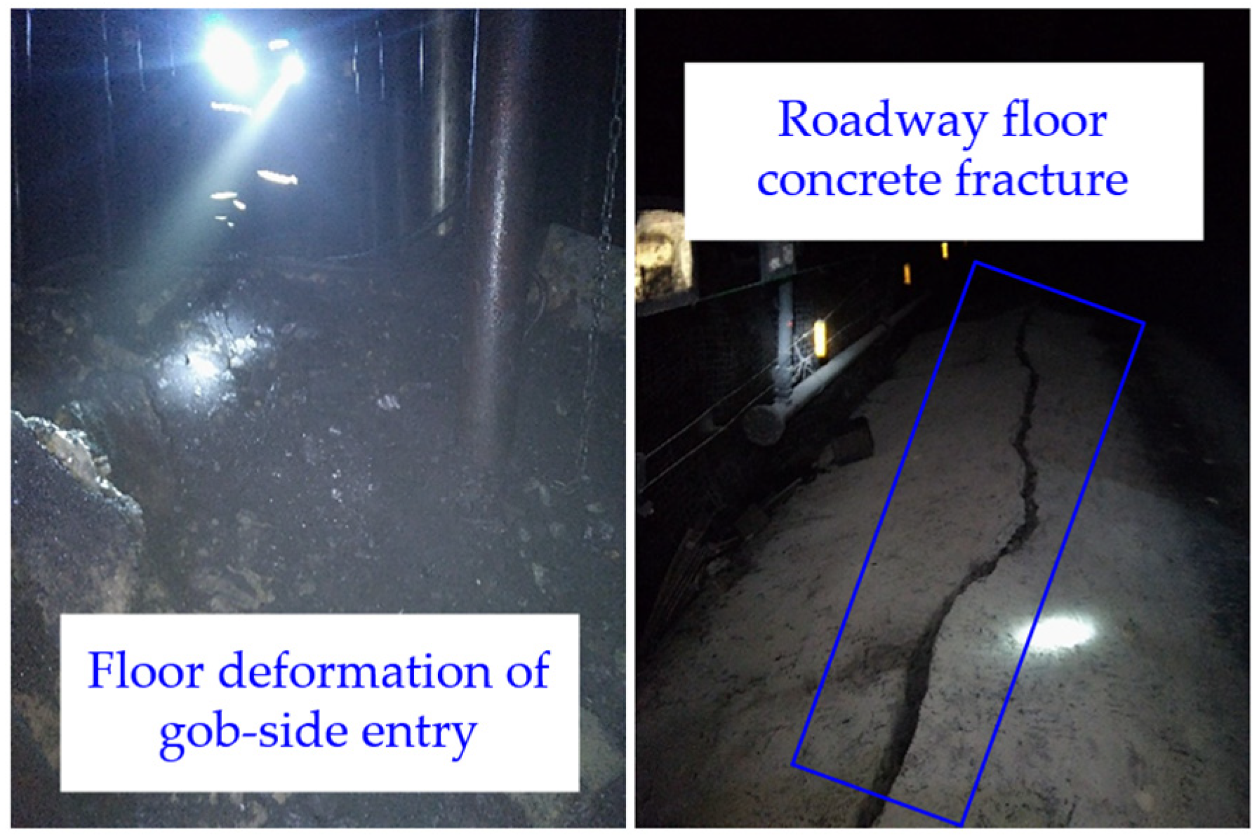
Cross section of roadway support. Note: Blue lines: anchor stock; Pink lines: anchor cable. The auxiliary transportation roadway of the N2301 working face has great deformation with the advanced working face, especially serious floor heave (see Figure 3). The roadway retaining behind the working face is severely deformed according to on-site research. The largest deformation area of the roadway is 220 m behind the working face. The roof-to-floor convergence reaches 1044 mm. There are obvious cracks and heaves at the bottom of the concrete within 250 m in front of the working face, which significantly impacts the regular utilization of roadways and hinders the organization of production activities, thereby limiting the safe, efficient, and sustainable production of the mines. Thus, the floor heave control technology of the roadway should be studied in a targeted manner.
Figure 2.
Cross section of roadway support. Note: Blue lines: anchor stock; Pink lines: anchor cable. The auxiliary transportation roadway of the N2301 working face has great deformation with the advanced working face, especially serious floor heave (see Figure 3). The roadway retaining behind the working face is severely deformed according to on-site research. The largest deformation area of the roadway is 220 m behind the working face. The roof-to-floor convergence reaches 1044 mm. There are obvious cracks and heaves at the bottom of the concrete within 250 m in front of the working face, which significantly impacts the regular utilization of roadways and hinders the organization of production activities, thereby limiting the safe, efficient, and sustainable production of the mines. Thus, the floor heave control technology of the roadway should be studied in a targeted manner.

Figure 3.
Floor deformation of gob-side entry.
The roof and floor are drilled and sampled to accurately grasp the strata distribution characteristics of the roof and floor of the auxiliary transportation roadway. Drilling holes are vertical to the roof and floor of the roadway, with vertical depths of 22 and 10 m for roof and floor, respectively. Figure 4 shows the rock cores. The roadway floor consists of coal at 0–2.2 m downwards, mudstone and sandy mudstone at 2.2–6.2 m, siltstone layers at 6.2–7 m, and sandy mudstone at 7–10 m. There is no complete core above 10 cm. According to the RQD classification system, roadway floor is a rock with “extremely poor” integrity. There are mudstone and sandy mudstone at 0–3 m above the roadway roof. It is an immediate roof, with poor integrity. The sandstone layer appears at 3–12 m. It is the main roof, with good integrity. Sandy mudstone and mudstone layers are above 12 m.
Rock cores are subjected to the rock mechanics test to obtain the mechanical properties of the roof and floor strata and provide relevant mechanical parameters for numerical simulation (see Figure 5) [27,28]. The point load test was carried out for the broken cores of the floor. More complete rock cores are subjected to sample processing. Standard rock samples of φ50 × 100 mm, φ50 × 25 mm, and φ50 × 50 mm are used for single-axis compression, single-axis tensile, and shear resistance experiments. The point-load experiment uses axial loading to select roughly the same rock sample groups with a radial ratio less than or equal to 1.0. The sandstone layer of the roadway roof has high uniaxial compressive strength (about 60–80 MPa), with a Protodyakonov number of 6–8. Secondly, the roof mudstone and sandy mudstone are soft, with a Protodyakonov coefficient of 1–3 and low overall strength of the floor strata. Sandy mudstone has a Protodyakonov coefficient of 3.2 at 7–8 m vertical to the floor. The rest are soft rocks with a Platts coefficient of 1.5–2.5.
Roadway roof has a thick sandstone main roof with high hardness, which is not easy to break (see Figure 6). The gob-side immediate roof collapses with the stoping of the N2301 working face. The hard, thick main roof rotates and sinks to form a cantilever structure on the goaf side. The breaking line of the main roof is located above the solid coal of the next working face. Therefore, most weights of rocks are located above the auxiliary transportation roadway of the N2301 working face. The load is borne by the soft mold wall and the coal column. The filling body has higher stiffness than the soft coal body of the roadway floor. Then, vertical stress formed by overlying strata is transferred to the floor of the roadway through the filling body. Meanwhile, the roadway floor consists of thicker bottom coal and mudstone. The stratum lithology is soft and easily deformed and damaged by stress and mining, which causes the serious floor heave in the roadway.
3. Analysis of Floor Heave Mechanism of Roadway
The above text described the strata distribution characteristics and occurrence state of the roadway roof and floor. Furthermore, each stratum was tested for rock mechanics to briefly analyze the reasons for the floor heave of the roadway. Numerical simulation is used to study the stress distribution of surrounding rocks when the roadway is affected by the mining of the working face in this section. The results are analyzed in combination with numerical simulation. A mechanical model is established to explore the mechanism of floor heaves in the gob-side entry of the soft rock floor.
3.1. Stress Distribution Law of Gob-Side Entry Retaining Being Affected by Stoping
Finite difference numerical simulation software, FLAC3D, is used to establish a numerical simulation model according to the geological conditions and coal-rock mechanics parameters of the N2301 working face of the Ancient City Coal Mine in the Lu’an mining area (see Figure 7). The model size is 157 × 200 × 60 m. Rhino7.0 is used to create anchor bolt and cable units to constrain the peripheral and bottom displacements. Vertical stress σh = γh = 12.5 MPa is applied on the top of the model to simulate the ground stress field. In addition, a gradient load is applied in the Z axis, with a side pressure coefficient of 1. The Mohr–Coulomb constitutive model is adopted as the destruction criterion of coal and rock masses in the model. Figure 8 shows the numerical simulation parameters of each rock formation.
The N2301 working face was subjected to 100 m excavation to observe the stress change characteristics of roadway roof, floor, and two sides after the roadway is excavated to equilibrium. The horizontal stresses of the roadway roof and floor of the lag working face are released in mining the working face. The stress change characteristics of the leading section are observed. Therefore, horizontal stress measuring lines are arranged at 20 m in the rear of the working face, and 10, 20, 30, 40, and 50 m in front of the working surface. The scope ranges from 20 m above roof to 20 m below floor. Vertical stress measuring points of two sid”s ar’ set at 20, 40, and 60 m in the rear of the working face and 10 and 30 m in front of the working face, respectively. The measuring lines extend by 10 m from two sides to the rock body. Figure 9 shows the specific layout.
Stress is redistributed in the mining of the working face. The Y-axis direction of each measuring point is sliced to obtain the horizontal stress distribution (see Figure 10 and Figure 11). Horizontal stress is released due to the recovery of the working face at 20 m in the rear of the working face. Concentrated horizontal stress is greatly reduced around the roadway. The horizontal stress concentration area of the floor is affected by the lead abutment pressure of the working face and shifts to gob-side entry at 30 m in front of the working face. The horizontal stress concentration area of the floor is restored to the roadway floor at 40–50 m. The horizontal stress of the roof and floor has a consistent concentration position and degree. The stress concentration position of the roof is about 5 m above the roof of the roadway, with a maximum stress of about 18.4 MPa. The stress concentration position of floor is about 7 m below the roadway floor, with a maximum stress of about 18.2 MPa.
Figure 12 and Figure 13 show the vertical stress distribution of the two sides of the roadways. The leading section of the roadway has an affected area of lead abutment pressure on the side of the working face. The range of the affected area is reduced 30 m in front of the working surface. However, it is not restored to secondary stress after roadway driving. The lag section of the roadway has significant concentrated vertical stress on the solid coal side. Goaf releases stress in the filling body of the entry retaining. However, certain vertical stress still accumulates. The maximum vertical stress on the pillar side is about 24 MPa at 60 m in the rear of the working face. It is located about 9 m from the roadway wall to the rock masses. The degree of stress concentration gradually decreases in solid coal with decreasing lag distance in the roadway of the lag working face. The stress concentration range gradually shifts to the roadway center.
The roadway floor has a large horizontal stress concentration in front of the working face in mining the working face according to numerical simulation. The roadway is influenced by the lead abutment pressure within 30 m in front of the working face. The horizontal stress concentration area of the roadway floor shifts to the gob side. The roadway floor is mainly affected by the horizontal stress of the floor. The horizontal stress of entry retaining is released in the rear of the working face. Vertical stress accumulates in large quantities in the filling body of solid coal at two sides and the entry retaining. Moreover, the solid coal side has a larger concentration and influence scope than the filling body side. The roadway floor is affected by vertical stress on two sides.
3.2. Mechanical Analysis of the Floor Heave Mechanism of Gob-Side Entry Retaining
A mathematical model is established here to further study the floor heave mechanism of entry retaining according to the characteristics of mine rock pressure distribution [29]. Surrounding rocks on both sides of the roadway produce lateral support pressure kγh that is higher than original rock stress after the roadway is excavated (see Figure 14a). The support pressure acts on both sides of roadway floor to form vertical pressures that are symmetrical and consistent. The roadway floor is mainly affected by the original rock stress and support pressure. Immediate roof collapses after the recovery of the working surface. The main roof forms a cantilever beam structure on the side of the filling body of the entry retaining towards the goaf (see Figure 14b). The immediate roof consists of hard sandstone layers that are not easy to break according to the stratum distribution and mechanical properties in the first section. The weights of the suspended immediate roof and overlying rock are jointly borne by the filling body of entry retaining and the gangue in the goaf. Roadway floor is subjected to original rock stress γh, lateral support pressure k1γh of the solid coal side, pressure σ of the filling body of entry retaining, and pressure k2γh of the goaf. The lateral abutment pressure of the solid coal side significantly increases to change the force state of the filling body of entry retaining according to the change characteristics of stress distribution of the roadway before and after mining the working surface.
The pressure formation process and floor heave mechanism of the roadway floor can be analyzed according to the soil mechanical theory when the rock mass pressure on both sides of the roadway is large [30,31]. The gob side of the filling body has a cantilever structure. It forms a stress relief zone in the goaf on the side of the filling body. Stress k2γh is not considered. The self-weight stress of the overlying rocks and the stress of the suspended roof structure on the filling body of entry retaining are simplified to a uniform load σ1. Figure 15 shows the mechanical model of the filling body side.
The damage characteristics of the roadway floor are analyzed according to the soil mechanics theory (see Figure 15). When the roadway floor is in the ultimate equilibrium state, the angle between sliding surface DE and the horizontal line is ; the angle between the sliding surface CE and the horizontal line is . Then, ∠FED = ; ∠FDE = . EF is analyzed as a retaining wall. The active and passive pressures at different points of EF are expressed as follows.
where PA is the active pressure; σ1 the stress of overlying rock self-weight and suspended roof structure on the filling body of entry retaining; γ the bulk weight of the rock; y0 the limit damage depth of the floor on the filling body side of entry retaining; φf the converted friction angle of rock masses, is greater than the internal friction angle of the rock (φf = 40° for soft coal and mudstone). It is also a function of positive stress σ, φf = artanf. As the Protodyakonov coefficient f increases, φf gradually increases.
PA is smaller than PB in the range of EF above point E, where the floor rock body is in a plastic state. PA is equal to PB at point E, where the bottom slab rock body is in a state of extreme equilibrium. PA is smaller than PB in the range below point E, where the floor rock body is in an elastic state. Equations (1) and (2) are substituted into PA = PB according to the above analysis.
The limit damage depth of the floor on the filling body side of entry retaining y0 is obtained.
Slider FDE is in an active state to produce active pressure PA according to the soil mechanics theory. Slider FEC is in a passive state to produce passive-pressure PB. PA faces the roadway floor, and PB is in the opposite direction to PA. The difference between PA and PB is the actual thrust that pushes FEC to the left. It can be expressed as P.
Effective sliding force along EC is expressed as
The peak area of the lateral abutment pressure on the solid coal side of the roadway is simplified to uniform load k1γh. Then, the effective sliding force of the solid coal side on the roadway floor is expressed as
The floor heave deformation is caused by the combined force P0 of effective sliding force T0 on the side of the filling body and effective sliding force T0′ on the side of the solid coal. The effective sliding force of the roadway floor is affected by the vertical stresses k1γh of two sides, σ1, and φf (see Equations (8) and (9)). The combined effective sliding force significantly increases with the increased vertical stress of the two sides. A weaker floor leads to a smaller Protodyakonov coefficient, smaller φf, and more obvious extrusion characteristics of vertical stress of the two sides on the floor rock mass. Meanwhile, the deviation degree of the position where the combined effective sliding force acts on the roadway floor also increases with increased vertical stress difference between the two sides of the roadway.
Consequently, the floor heave of the roadway in front of the working face is caused by the horizontal stress concentration of the weak bottom coal and the soft floor. The working surface is affected by lead abutment pressure. The weak rock mass squeezes and flows towards the free surface of the roadway. The floor heave of the roadway in the rear of the working face is caused by the horizontal stress concentration of solid coal on two sides of the roadway and the filling body of the entry retaining. The floor of the roadway is squeezed to form an asymmetric sliding force towards the free surface on two sides of floor. Asymmetric floor heave is generated in the roadway under the non-uniform superposition of the sliding forces of the two sides.
4. Floor Heave Control Technology
The roadway floor heave in front of the working face is caused by the horizontal stress concentration of the floor according to the above analysis. Vertical stress of two sides transfers to form superposed sliding force, which causes the floor heave of entry retaining in the rear of the working face. Roadway floor heave is controlled by reducing stress concentrations of floor and two sides or transferring the high-stress area of surrounding rocks of the roadway to the deep part. The floor heave control technology of “pressure relief by floor loosening blasting and pressure relief by roof cutting of gob side” is proposed by changing the stress state of surrounding rocks. Loose floor blasting pressure relief can form a weakening area of surrounding rocks. Roadway floor and the two stress concentration areas are transferred to the deep part of surrounding rocks, which reduces the impact of the horizontal stress concentration on the floor heave. Pressure relief by roof cutting at the gob side entry can reduce the vertical stress of solid coal and the filling body at both sides of roadways, which decreases the resultant sliding force on the floor heave.
4.1. Pressure Relief Mechanism of Floor Loosening Blasting
The mechanism and related parameters of pressure relief by floor loosening blasting are explored to further study the floor heave control effect. Concentrated stress caused by entry driving occurs close to the periphery of the roadway before the loosening blasting of the roadway floor. The surrounding rocks of the roadway are in a high-stress state, which causes plastic damage and strong deformation of the surrounding rocks. The support body is damaged due to its inability to control and adapt to the movement of the large surrounding rocks. The basic principle of achieving stress transfer of surrounding rocks by artificial loosening blasting is proposed based on the characteristics of stress changes during the damage of high-stress roadways. Blasting drilling holes are arranged at the two bottom corners of the roadway floor before the severe deformation of the roadway (see Figure 17). Loosening blasting is conducted in the high-stress area of the floor to form the weakened area of surrounding rocks, which releases the high horizontal stress of the floor. The broken and loosen area can block horizontal stress propagation, which transfers the peak stress area of the two sides and floor to the deep part of the surrounding rock. The surrounding rock damage in the floor is decreased to maintain roadway stability.
The control effect of loosening blasting on the floor heave of the roadway is studied by similar simulation experiments. The model of 3200 × 200 mm × 1800 mm (L × W × H) has a geometric similarity ratio of 1:20, a bulk–weight similarity ratio of 1:1.5, and a stress similarity ratio of 1:30. The roadway of 250 × 190 mm has initial stress applied to the roof of 0.42 MPa and a side pressure coefficient of 1 in the model. Then the lateral stress of 0.42 MPa is applied to the sides.
Figure 18 shows the scaled physical model. Two roadways are excavated on the same model according to the similarity ratio. One adopts the original support conditions; the other is conducted with floor loosening blasting based on the original support conditions. The bolt is simulated by the fuse; the anchoring agent is simulated by gypsum water. High-precision hydraulic regulator WY30-VIIIA is used as the loading control device. Stress measuring points are arranged at 120, 240, and 480 mm below the roadway floor of the model. A vibrating soil pressure gauge is used to monitor the stress of the roadway floor. Displacement measuring points are arranged at 100, 200, 300, and 400 mm below the roadway centerline to monitor the floor displacement.
The failure of similar simulated roadway layout areas is enlarged. The surrounding rocks of roadways with and without loosening blasting are deformed, with obvious floor heave (see Figure 19). However, the roadway with loosening blasting has significantly smaller roof-to-floor and two-side convergences than the roadway without loosening blasting. Furthermore, the cross-section of the roadway remains relatively intact. The roadway roof without loosening blasting is broken. The two sides are severely damaged and tend to be embedded in the floor, with a convergence of about 20 mm. The roadway with loosening blasting has small floor heave and complete roof. The two sides are slowly deformed, with a convergence of about 10 mm.
The shallow part of the floor without loosening blasting has a large displacement according to the deformation monitoring of the roadway floor. The maximum surface displacement of the roadway floor reaches 20 mm (see Figure 20a,b). The deformation of the floor at 100 mm from the midline of the roadway is 11 mm. The displacements at 200–400 mm from the midline are concentrated. The maximum surface displacement of the roadway floor is 14 mm after pressure relief. It is 43% lower than that before pressure relief. The floor heave control effect is obvious. Surrounding rocks of the roadway without loosening blasting show continuous deformation. The surrounding rock deformation of the roadway with loosening blasting decreases sharply at 200–350 mm below the roadway near the blasting pressure relief zone. Partial deformations are absorbed by the blasting pressure relief zone. Moreover, the stratum at 450 mm below roadway floor without blasting displays obvious floor heave of about 3–7 mm. The stratum of the blasted roadway is unchanged. Therefore, pressure relief by blasting can control deep floor deformation.
When stress is loaded to 0.7 MPa, the maximum horizontal stress (0.212 MPa) of roadway floor before pressure relief is located at 240 mm below floor. It is generally higher than 0.056 and 0.039 MPa at 120 and 480 mm below floor (see Figure 21a,b). The maximum horizontal stress (0.223 MPa) of the roadway floor after pressure relief is located at 480 mm below floor. It is generally higher than 0.0399 and 0.049 MPa at 120 and 240 mm below floor. The horizontal stress concentration position of roadway floor is transferred from 240 to 480 mm below floor after pressure relief by blasting according to the above results. The horizontal stress of roadway floor is transferred from the shallow part to the deep part of the surrounding rocks due to pressure relief by blasting. Moreover, horizontal stress at the shallow part of floor (120 mm) decreases from 0.056 MPa before blasting to 0.0399 MPa after blasting. Stress on the shallow part of roadway floor is released to a certain extent because of pressure relief by blasting.
The deformation of the roadway floor can be controlled by loosening blasting according to the above research. In addition, the horizontal stress concentration area of the roadway is transferred to the deep parts of the surrounding rocks.
4.2. Research on Loosening Blasting Parameters
The blasting parameters of roadway floor are studied to further determine the floor blasting scheme. It involves the blast hole depth, blasting spacing, and charge structure. The blast hole depth reaches the peak stress area of the roadway floor. After that, the horizontal stress of the roadway floor can be released and transferred to the deep part of surrounding rocks. Meanwhile, blast-hole length is determined based on the principle of not destroying the integrity of surrounding rocks and the stability of the bracket between the loose crushing zones. The horizontal stress peak depth of the blast hole is calculated according to Kastner’s Formula (10) [32].
where a is the radius of the roadway, m; p0 the original rock stress, MPa; c the cohesion, MPa; and φ the internal friction angle, °.
The plastic zone radius of the roadway is calculated to be 6.51 m, and the horizontal stress peak depth of roadway floor is 4.61 m according to the above formula. The blast hole depth is greater than 4.61 m by theoretical calculation. There are areas of mudstone, sandy mudstone, and interbedded sand within 6.2 m of roadway floor according to the strata distribution of the floor. A siltstone layer with a thickness of about 1 m appears when the floor is 6.2–7 m. The blast hole depth is preliminarily designed to be 7 m from the floor to ensure that the horizontal stress of the floor is transferred to the deep parts instead of destroying the mechanical properties of shallow surrounding rocks.
The internal action of blasting forms cavities, crushing, fracture, and vibration circles in surrounding rocks according to blasting theory. The coal–rock mass produces slip and crushing surfaces under detonation waves and detonation products at high temperatures and pressures, which form the crushing area in the crushing circle. The coal–rock mass has not been destroyed in the blasting fracture circle. The annular cracks are formed after the structure is unloaded due to the anisotropy of the rocks. The spacing between the blasting holes directly affects the stress transfer effect of the surrounding rocks. The fracture circles formed by blasting inside surrounding rocks are suitable. The radius of the blasting fracture circle is calculated based on the explosive stress wave (see Equation (11)) [32].
where e is the proportional coefficient of tangential and radial stress, e = μ/(1 − μ); pc initial peak stress on the wall of the blast hole, MPa; ST the tensile strength of rocks, MPa; e′ the attenuation coefficient, e′ = 2 − μ; and rb the radius of the blast hole, m.
pc is calculated by Equation (12)
where ρ0 is the explosive density, kg/m3; D1 the explosive velocity, m/s; rc the radius of the explosive column, m; n the stress intensification factor, and n = 8–11.
Three-stage permitted emulsified explosives for coal mines are used for blasting. Here, ρ0 = 1120 kg/m3; D1 = 4800 m/s, rc = 0.0225 m; rb = 0.0275 m; dynamic Poisson’s ratio µ = 0.25; e = 0.33; e’ = 1.75. The radius of fracture circle Rp is 2.08 m by calculation. The spacing between the blast holes is double the radius of the fracture circle to ensure penetration of the fracture circle. The spacing is designed to be 4 m according to the actual blasting construction effect of the roadway.
The charge structure includes the relationship between the explosive loading mode and the structure. Forward blasting is used to minimize the effect of the detonation wave on the shallow surrounding rocks of the roadway floor. In other words, the detonation wave is propagated to the bottom of the hole. The charging method consists of coupled and uncoupled charging. The impact force of the detonation wave on rocks is artificially reduced for uncoupled charging during the blasting process. The main energy is converted into stress waves that can propagate in a wide range and act on rocks, which shrinks the crushing area. The stress wave becomes the main energy form destroying the rock mass. The range of the fracture zone is enlarged, which fully utilizes explosive energy. Air or water are used as an uncoupled medium in the application of deep hole loosening blasting technology at present. Generally, the uncoupling coefficient is considered to be 1.0–2.0. The planned drilling diameter is 55 mm, with a cartridge diameter of 45 mm. The uncoupled charge coefficient is calculated by Equation (13).
where db is blast hole diameter, mm; dc the cartridge diameter, mm.
Table 1 presents the loosening blasting parameters of roadway floor.
5. Field Measurement and Analysis
The technical scheme of “pressure relief by floor loosening blasting and pressure relief by gob-side roof cutting” is implemented in the auxiliary transportation roadway during the recovery of the N2301 working face. The floor loosening blasting adopts φ45 × 440 mm three-stage emulsified explosives allowed in coal mines, with four rolls per hole. Two detonators are installed in each hole to prevent the appearance of blind cannons. The detonators are connected to the lead wires and drawn out of the hole after forward charging. Detonator FD-200DA is used based on “parallel connection in the hole and serial connection outside the hole”. Figure 22 shows the charge structure.
Pressure relief by roof cutting requires cutting off the overlying hard roof on the stope. The blasting parameters are determined according to the strata distribution characteristics and related parameters: the spacing is 2 m; the hole depth is 12 m; the accelerated cement sealing hole is 4 m; the length of the charge section is 8 m; the drilling diameter is 65 mm; the angle between the blast hole and level is 75°; and the diameter of the condenser tube is 50 mm. Figure 23 shows the specific arrangement.
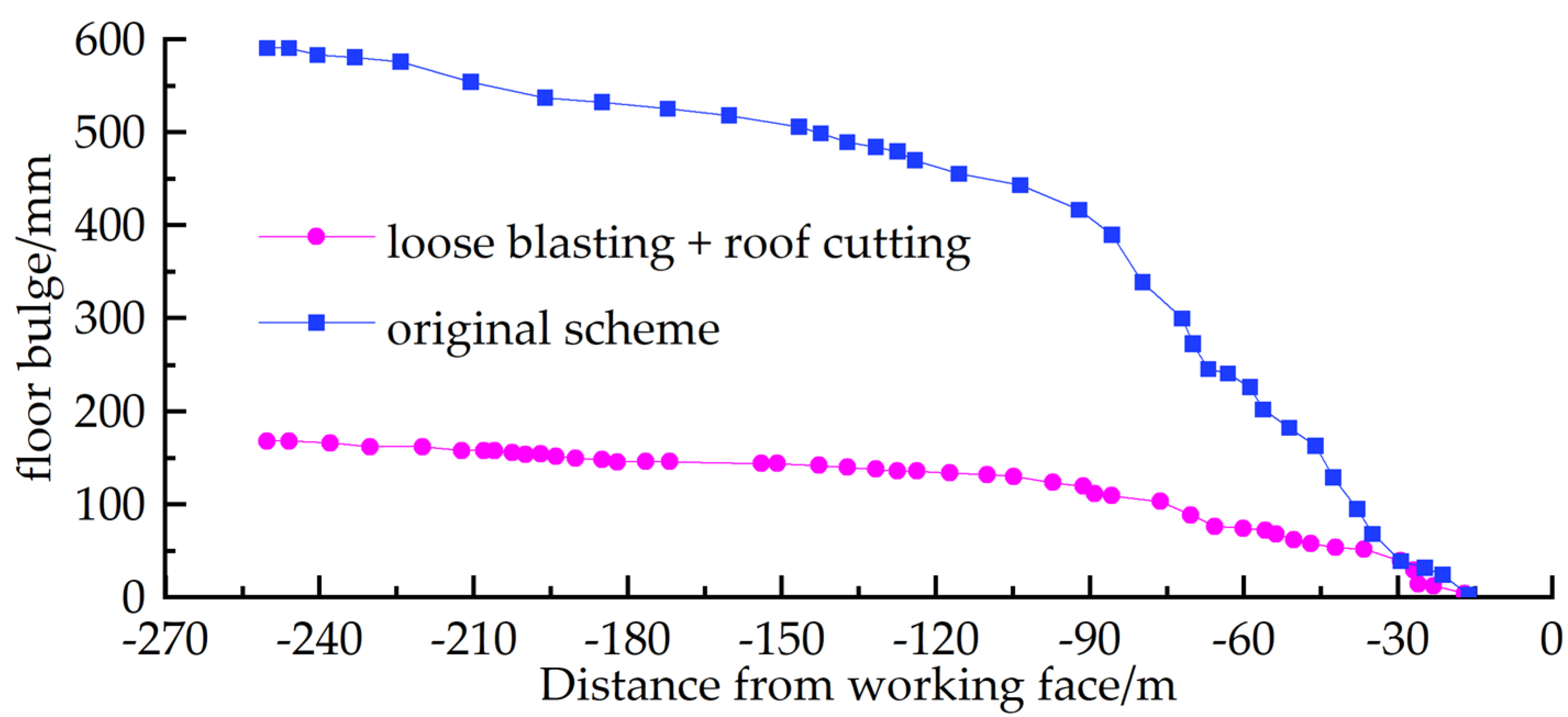
Displacement measuring points are arranged at 15 m in the rear of the working face to monitor the roadway deformation according to the above scheme. Figure 24 shows the monitoring results. The roadway within 100 m in the rear of the working face has a high speed of floor heave, which gradually slows down when the distance is larger than 100 m. The original roadway support is adopted to derive the floor heave of 590 mm at 250 m in the rear of the working face. Floor heave decreases to 168 mm after adopting “floor loosening blasting and pressure relief by roof cutting”. The control of floor heave has a pronounced effect, guaranteeing the sustainability of mining in the working face.
6. Discussion
The immediate floor of the roadway is a weak and broken coal body with a thick and hard roof according to the above experimental results, related theoretical analysis, and field practice. The roof and two sides have great support strength, while the floor is in an unconstrained state. The structural strength of the surrounding rocks is much smaller than that of the roof and two sides. The roadway in the leading section of the working face is affected by the lead abutment pressure and ground stress field during mining of the working face, which causes the squeeze flow of weak coal on the roadway floor toward the free surface. Gob-side entry retaining in the rear of the working face has vertical stress transfer between the solid coal of the two sides and the filling body. The roadway floor is squeezed to form asymmetric sliding force towards the free face on two sides of the floor, which produces asymmetric floor heave under the non-uniform superposition of the sliding forces of two sides. The floor heave control technology of “pressure relief by floor loosening blasting and pressure relief by gob-side roof cutting” is proposed according to the floor heave mechanism of the roadway. The core is to change the stress state of surrounding rocks. Engineering application research shows that its floor-heave control effect is obvious.
Control measures for the floor heave of soft-rock roadways are often achieved based on the modification and reinforcement of the surrounding rocks of floor by anchor cables, grouting, and anti-arching [33,34,35]. A large amount of project quantity affects mining when the above-mentioned technical measures are applied. Moreover, the roadway is affected by mining at the later stage, which made it difficult to repair the floor heave and the roadway [36,37]. Although the implementation of the above-mentioned technical measures in the mining roadway can control floor heave to a certain extent, it is not conducive to economic benefits. Therefore, considering the above factors, mine treatment measures for roadway floor heave are often implemented in main roadways or chambers, and digging out of the floor heave is still mainly used in mining roadways [38,39].
The work analyzed the floor heave of soft-rock floor along gob-side entry to propose the floor heave control scheme of “pressure relief by blasting of loose floor and pressure relief by side roof cutting in the goaf.” The amount of project quantity implemented in the scheme was small, with high economic benefits and an obvious effect. It has a wide range of applicability and potential for widespread use in the mining roadway and provides an idea for managing floor heave.
7. Conclusions
The roof and floor characteristics were analyzed by laboratory experiments with the project profile of the N2301 working face of the Ancient City Coal Mine. Numerical simulation was used to study the effect of mining the working face on the stress distribution of the roadway. The floor heave mechanism of gob-side entry retaining was explored through mathematical analysis to propose the floor heave control technology of gob-side entry retaining of weak floor in thick seams. The floor heave control effect was verified by field practice to obtain the following conclusions after studying the control technology by simulation.
- (1)
- The floor was a weak stratum, and the roof was a thick and hard sandstone layer for the auxiliary transportation roadway of the N2301 working face of the Ancient City Coal Mine. The roadway in front of the working face was affected by the horizontal stress and lead abutment pressure of the floor. The vertical stress of entry retaining in the rear of the working face accumulated in large quantities in solid coal of the two sides and the filling body of entry retaining. Moreover, the solid coal side had a larger concentration and influence range than the filling body side. The floor was affected by the vertical stress of the two sides.
- (2)
- The floor heave of entry retaining was caused by concentrated vertical stress in the solid coal and filling body of two sides. The floor was squeezed by the two sides to form an asymmetric sliding force towards the free face of the floor. Moreover, sliding force increased with the increased vertical stress of the two sides. The deviation degree between the effective sliding force and the position of the roadway floor also increased with the increased vertical stress difference between the two sides of the roadway. The weaker floor led to a smaller converted friction angle. Furthermore, the vertical stress of the two sides had more significant extrusion characteristics on the rock body of the floor.
- (3)
- A weakening area of surrounding rocks was formed based on the floor heave control technology of “pressure relief by floor loosening blasting and pressure relief by gob-side roof cutting”. The stress concentration areas of roadway floor and two sides were transferred to deep surrounding rocks. The vertical stress in the solid coal and filling body of two sides was reduced to decrease the resultant sliding force acting on the roadway floor.
- (4)
- The roadway within 100 m in the rear of the working face had a high speed of floor heave, which gradually slowed down when the distance was larger than 100 m. Floor heave decreased to 168 mm after adopting “floor loosening blasting and pressure relief by roof cutting” at 250 m in the rear of the working face. Floor heave was well controlled. The research findings can furnish a more scientifically sound theoretical foundation for controlling floor heave in gob-side entry retaining, thus providing a fundamental guarantee and impetus for the sustainable advancement of gob-side entry retaining technology in coal mining.
Author Contributions
Conceptualization, Z.L. and Y.Z. (Yidong Zhang); methodology, L.H. and Q.M.; software, Z.L., Q.M. and Y.Z. (Yu Zheng); validation, G.S. and Y.Z. (Yu Zhang); formal analysis, Z.L.; writing—original draft preparation, Z.L.; writing—review and editing, Y.Z. (Yidong Zhang) and Z.L.; project administration, Y.Z. (Yu Zheng); data curation, W.Y.; investigation, Y.Z. (Yu Zheng); resources, G.S. All authors have read and agreed to the published version of the manuscript.
Funding
The work was funded by the Key Project of Joint Funds of the National Natural Science Foundation of China (grant number U1903209); the Key coal-based scientific and technological research projects in Shanxi Province in 2014 (grant number MJ2014-12).
Institutional Review Board Statement
Not applicable.
Informed Consent Statement
Not applicable.
Data Availability Statement
The data that support the findings of this study are available on request from the corresponding author. The data are not publicly available due to privacy orethical restrictions.
Acknowledgments
The authors would like to thank the engineering technicians in Gucheng Coal Mine for their enthusiastic assistance and suggestions.
Conflicts of Interest
The authors declare no conflict of interest.
References
- Zhou, X.M.; Wang, S.; Li, X.L. Research on Theory and Technology of Floor Heave Control in Semicoal Rock Roadway: Taking Longhu Coal Mine in Qitaihe Mining Area as an Example. Lithosphere 2022, 2022, 3810988. [Google Scholar] [CrossRef]
- Yang, H.Z.; Wang, D.P.; Ju, W.J. Asymmetric Damage Mechanisms and Prevention Technology in Large-Section Gob-Side Entry Retaining. Sustainability 2023, 15, 739. [Google Scholar] [CrossRef]
- Yuan, S.C.; Zheng, G.S.; Qian, Z.W. Research on water and sand inrush mechnism and repair technology of shaft rupture in inclined shaft. Coal Sci. Technol. 2019, 47, 113–118. [Google Scholar]
- Yang, H.Q.; Zhang, N.; Han, C.L. Stability Control of Deep Coal Roadway under the Pressure Relief Effect of Adjacent Roadway with Large Deformation: A Case Study. Sustainability 2021, 13, 4412. [Google Scholar] [CrossRef]
- Hu, C.W.; Yang, X.J.; Huang, R.F. Presplitting Blasting the Roof Strata to Control Large Deformation in the Deep Mine Roadway. Adv. Civ. Eng. 2020, 2020, 1449–1462. [Google Scholar] [CrossRef]
- Yuan, S.C.; Han, G.L. Combined drilling methods to install grout curtains in a deep underground mine: A case study in southwest china. Mine Water Environ. 2020, 39, 902–909. [Google Scholar] [CrossRef]
- Lai, X.; Xu, H.; Shan, P. Research on Mechanism and Control of Floor Heave of Mining-Influenced Roadway in Top Coal Caving Working Face. Energies 2020, 13, 381. [Google Scholar] [CrossRef] [Green Version]
- Wu, J.X.; Fang, S.L. Mechanical mechanism and control technology of floor heave of high stress thick coal seam under dynamic pressure. Coal Sci. Technol. 2018, 12, 86–91. [Google Scholar] [CrossRef]
- Li, J.B.; Yi, S.X. Study on deformation and rock failure mechanism of floor rock mass with thin aquifuge near Ordovician limestone. Coal Sci. Technol. 2021, 12, 173–179. [Google Scholar]
- Zhang, K.X.; Ma, Z.Q.; Yang, Y.M. Technology of Floor Heave Prevention and Control in Fully-Mechanized Thick Seam Top Coal Caving Mining Face with High Intensity Mining. Coal Sci. Technol. 2014, 11, 33–36. [Google Scholar]
- Gao, X.X.; Guo, Y.; Qiao, Z.Q. Research on Control Technology of Roadway Floor Heave in Daliuta Coal Mine. Min. Res. Dev. 2021, 9, 45–68. [Google Scholar]
- Fan, G.T.; Zhang, D.D.; Zhang, L.J. Research on Floor Heave Mechanism and Control of Mining Roadway in Fully Mechanized Mining Face with Deep Depth and Large Mining Height. Min. Res. Dev. 2022, 5, 95–100. [Google Scholar]
- Yang, R.S.; Zhu, Y.; Li, Y.L. Floor heave mechanism and control measures of layered floor in weakly cemented soft rock roadway. J. Min. Saf. Eng. 2020, 3, 443–450. [Google Scholar]
- Zhang, G.Y.; Zhao, L.; Shnag, Y.Q. Study on key control technology of floor heave in soft rock roadway. Coal Sci. Technol. 2019, 11, 63–67. [Google Scholar]
- Yang, R.S.; Li, Y.L.; Guo, D.M. Deformation reasons and support technology of deep and high-stress soft rock roadway. J. Min. Saf. Eng. 2017, 6, 1035–1041. [Google Scholar]
- Sun, L.H.; Yang, B.S.; Sun, C.D. Experimental research on mechanism and controlling of floor heave in deep soft rock roadway. J. Min. Saf. Eng. 2017, 2, 235–242. [Google Scholar]
- Lu, J.; Gong, P.L.; Li, P. Research on the Mechanism of Floor Heave and Borehole Pressure Relief Technology in Deep Soft Rock Roadway. Min. Saf. Environ. Prot. 2019, 6, 35–41. [Google Scholar]
- Gao, L.S.; Zheng, X.J.; Wang, Y.C. Study on mechanism of pressure relief by deep hole blasing and technique system to control floor heave on the roadway floor. China Min. Mag. 2020, 8, 104–110. [Google Scholar]
- Zhang, C.S. Surrounding Rock Control Technology of Roadway Adjacen Goaf in Fully Mechanized Large Height Mining Face. Coal Sci. Technol. 2013, 41, 6–7. [Google Scholar]
- Wang, Z.Q.; Wang, P.; Lv, W.Y. Mechanism and control of asymmetric floor heave in gob-side entry. J. Min. Saf. Eng. 2021, 2, 335–346. [Google Scholar]
- Zhai, X.X.; Qin, L.T.; Chen, C.Y. Combined Supporting Technology of Anchoring and Grouting and Floor Relief in Deep Chamber of Belt Conveyor. Chin. J. Undergr. Space Eng. 2017, 5, 1363–1372. [Google Scholar]
- Yu, G.Y.; Wang, J.; Sun, H. Mechanism and comprehensive control techniques for large deformation of floor heave in block filling gob-side entry retaining. J. Min. Saf. Eng. 2022, 2, 335–346. [Google Scholar]
- Qin, X.H.; Zhang, Y.H.; Wang, J.J. Experimental Study on Floor Heave Mechanism of Soft Rock Roadway Based on Numerical Simulation. Min. Res. Dev. 2019, 9, 51–56. [Google Scholar]
- Zhao, H.B.; Liu, Y.H.; Cheng, H. Mechanism and prevention measures of asymmetric floor heave in mining roadway of Huipodi Coal Mine. J. Min. Sci. Technol. 2020, 6, 638–647. [Google Scholar]
- Zhang, W.K.; Liu, D.L.; Sun, D.Z. Failure mechanism and active control technology of deep roadway in Chengjiao Coal Mine. Min. Saf. Environ. Prot. 2020, 3, 76–81. [Google Scholar]
- Jing, H.H.; Sun, X.M.; Heng, C.Y. Study on compound support technology for mining gateway in tilted strata in deep mine. Coal Sci. Technol. 2001, 8, 24–26. [Google Scholar]
- Zhang, C.; Bai, Q.S.; Han, P.H. Strength Weakening and its Micromechanism in Water–rock Interaction, a Short Review in Laboratory Tests. Int. J. Coal Sci. Technol. 2023, 10, 10. [Google Scholar] [CrossRef]
- Han, P.H.; Zhang, C.; Wang, X.J. Study of Mechanical Characteristics and Damage Mechanism of Sandstone under Long-term Immersion. Eng. Geol. 2023, 10, 107020. [Google Scholar] [CrossRef]
- Qian, M.G.; Shi, P.W.; Xu, J.L. Ground Pressure and Strata Control; China University of Mining and Technology Press: Xuzhou, China, 2010. [Google Scholar]
- Wu, S.G. Soil Mechanics; Chongqing University Press: Chongqing, China, 2016. [Google Scholar]
- Li, T.L. Mine Rock Mechanics; Chongqing University Press: Chongqing, China, 1991. [Google Scholar]
- Hou, C.J. Tunnel Surrounding Rock Control; China University of Mining and Technology Press: Xuzhou, China, 2010. [Google Scholar]
- Cao, Z.A.; Liu, Y.M.; Gao, M.S. Study on Downward Borehole Bolt and Grouting Reinforcement Technology of Mine Soft and Weak Mudstone Roadway Floor. Coal Sci. Technol. 2016, 44, 12–17. [Google Scholar]
- Li, S.B.; Fan, H.; Liu, W.R. Techniques and Principle of Floor Heave Controlling of Soft Rock Roadway in Deep. Coal Mining Technology 2016, 21, 78–80+42. [Google Scholar]
- Chang, J.C.; He, L.P. A Research on Cable Supporting and Curtain Grouting of Hydraulic Hose Controlling the Roadway Floor Heave in Deep Coal Mine. J. Min. Saf. Eng. 2015, 32, 968–972. [Google Scholar]
- Yu, W.J.; Wang, W.J.; Huang, W.Z. Deformation Mechanism and Rework Control Technology of High Stress and Soft Rock Roadway. J. China Coal Soc. 2014, 39, 614–623. [Google Scholar]
- Wang, C.; Wu, Y.P.; Huang, X.P. Mechanism of floor failure of roadway supported by inverted arch under complicated surrounding rocks and its control. J. Min. Saf. Eng. 2018, 36, 959–967+976. [Google Scholar]
- Jing, L.W.; Yan, Y. Mechanism and Control Technology of Floor Heave in High Stress Soft Rock Chamber. Coal Eng. 2022, 54, 112–117. [Google Scholar]
- Mu, C.Y.; Ma, Z. Deformation Mechanism Analysis and Supporting Technology for Rock Roadway Floor Heave Under Deep Complex Geological Condition. Saf. Coal Mines 2016, 47, 95–98. [Google Scholar]
Figure 1.
Working face and roadway layout.

Figure 4.
Drilling cores of the roof and floor strata of the roadway.

Figure 5.
Rock mechanics test.

Figure 6.
Roadway floor affected by the strata structure.

Figure 7.
Numerical calculation model.
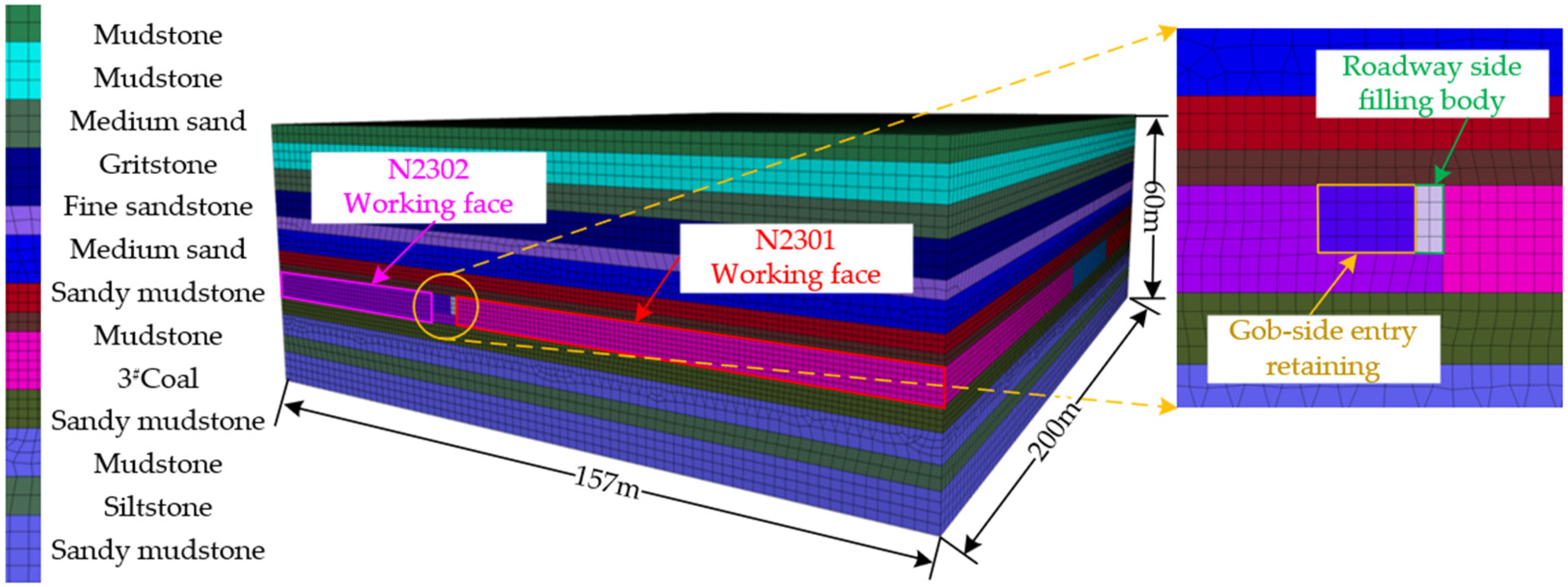
Figure 8.
Numerical simulation parameters of each rock formation. Note: L: rock stratum name; De: density; Bu: volume modulus; Sh: shear modulus; Coh: cohesion; F: internal friction angle; Ten: tensile strength.
Figure 8.
Numerical simulation parameters of each rock formation. Note: L: rock stratum name; De: density; Bu: volume modulus; Sh: shear modulus; Coh: cohesion; F: internal friction angle; Ten: tensile strength.

Figure 9.
Layout of measuring points.

Figure 10.
Horizontal stress nephogram in the recovery of the working face.

Figure 11.
Horizontal stress curves of different measuring points.

Figure 12.
Vertical stress nephogram mining the working face.
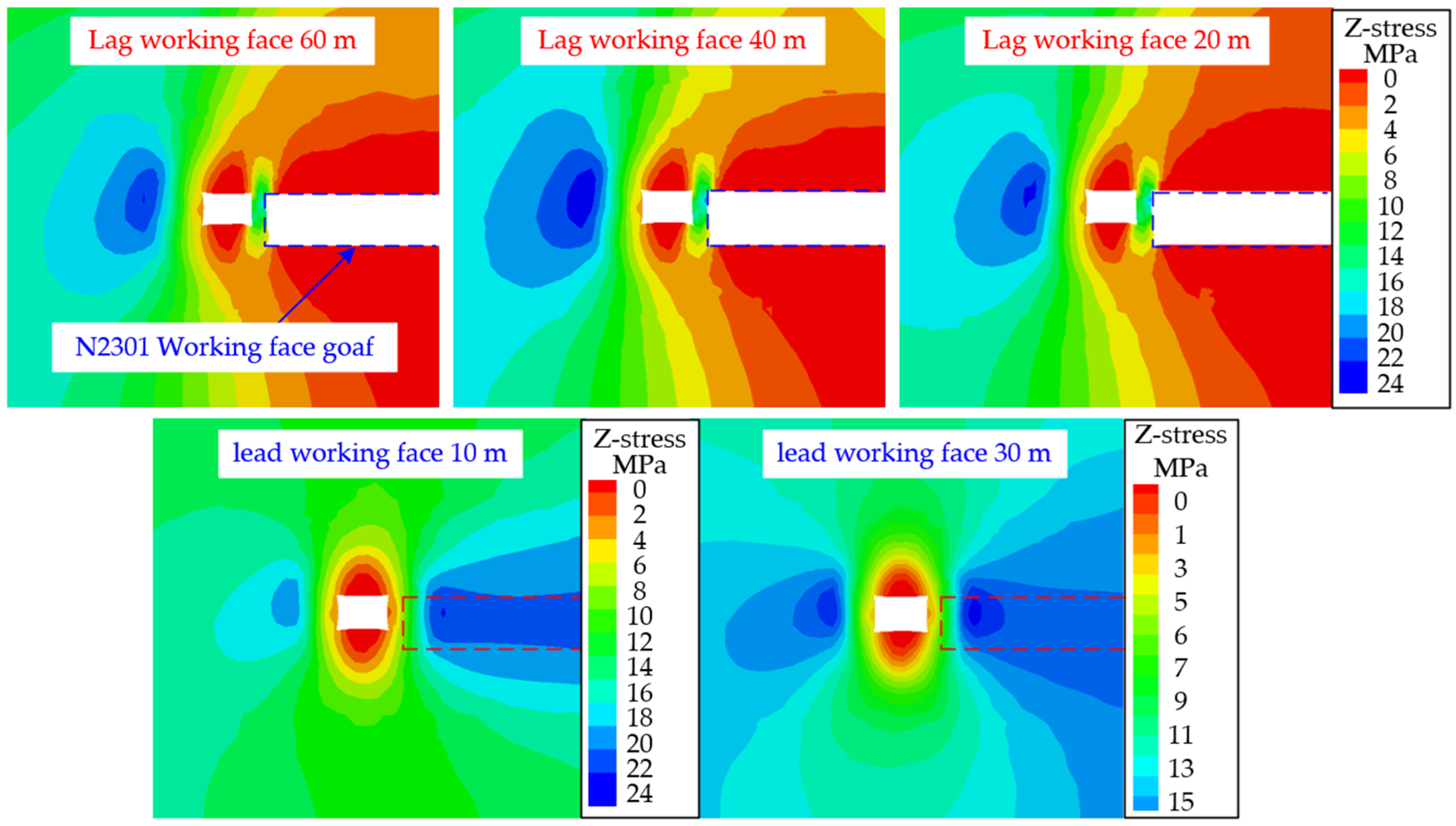
Figure 13.
Vertical stress curves of different measuring points.
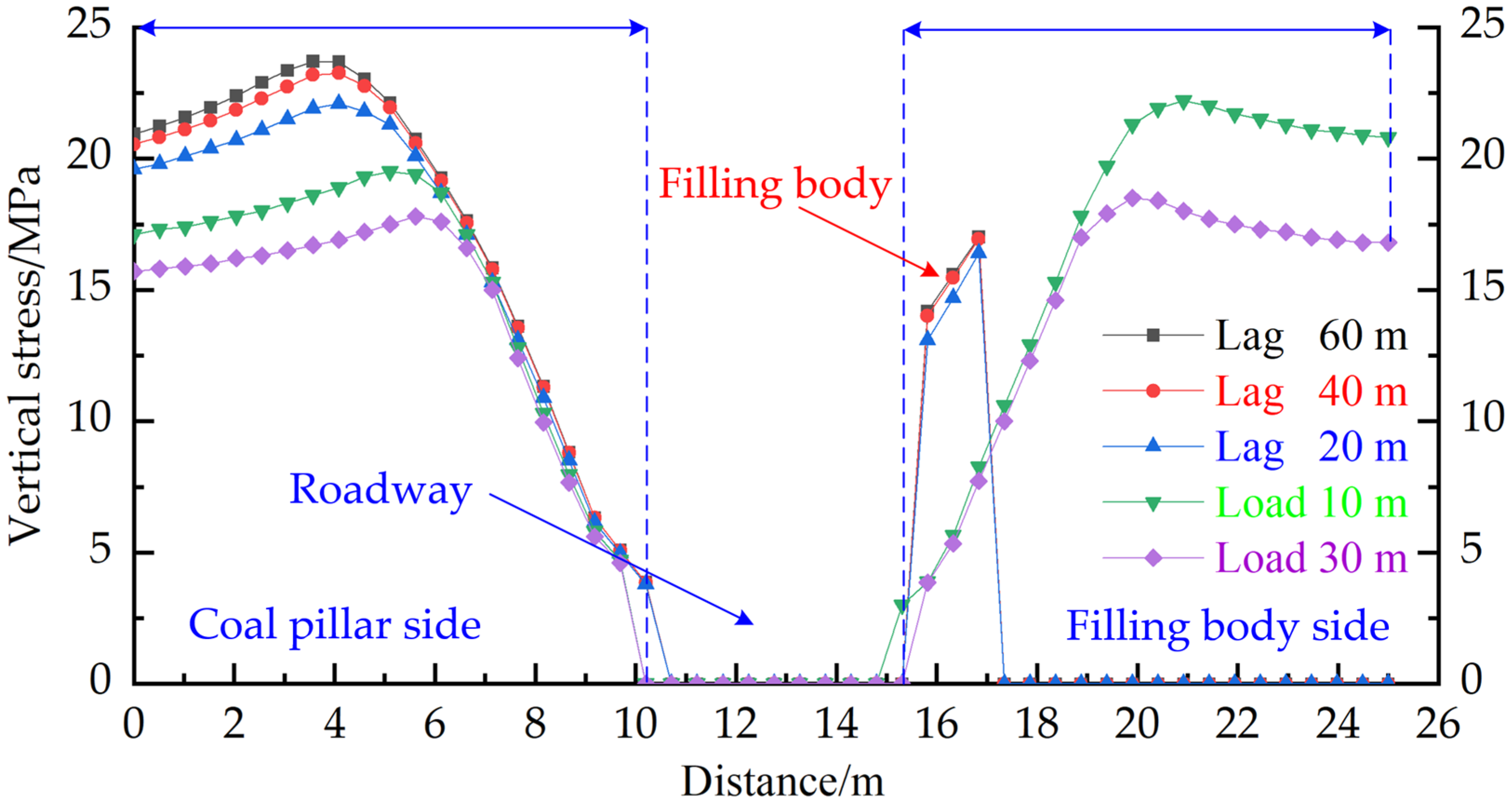
Figure 14.
Stress of roadway floor after excavating the roadway and mining the working face. (a) After excavating the roadway. (b) After mining the working face.
Figure 14.
Stress of roadway floor after excavating the roadway and mining the working face. (a) After excavating the roadway. (b) After mining the working face.
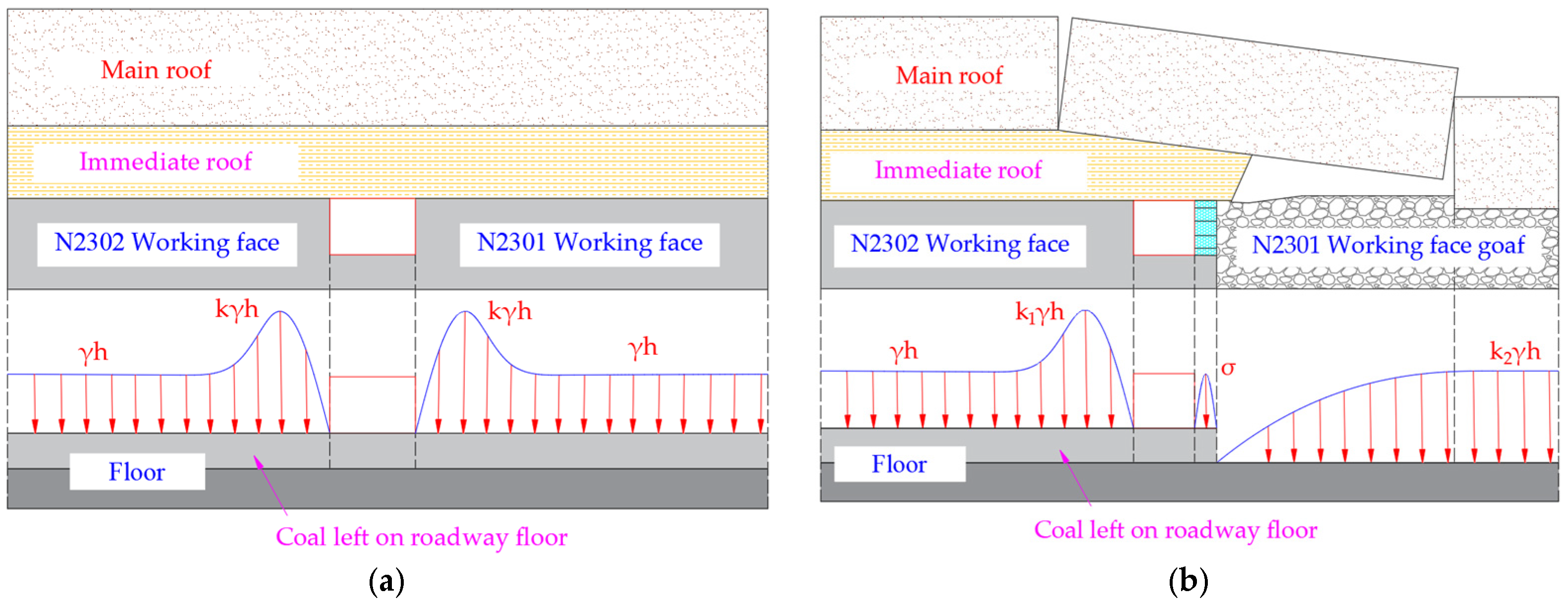
Figure 15.
Floor stress model on the filling body side of entry retaining.

Figure 16.
Sliding force superposed with floor damage.

Figure 17.
Pressure relief principle of roadway floor by loosening blasting.

Figure 18.
Scaled physical model.

Figure 19.
Model deformation after the test.

Figure 20.
Floor deformations by simulation. (a) Floor deformation without blasting; (b) Blasting floor deformation.
Figure 20.
Floor deformations by simulation. (a) Floor deformation without blasting; (b) Blasting floor deformation.

Figure 21.
Floor stress condition by simulation. (a) Pressure of floor without blasting; (b) Pressure of blasting floor.
Figure 21.
Floor stress condition by simulation. (a) Pressure of floor without blasting; (b) Pressure of blasting floor.

Figure 22.
Charge structure.

Figure 23.
Floor heave control scheme.

Figure 24.
Floor heave monitoring curve.

Table 1.
Summary of blasting parameters.
| Position | Blast Hole Length/m | Spacing/m | Row Spacing/m | Angle/(°) | Hole Sealing Length/m | Loaded Length/m | Blast Hole Diameter/mm | Cartridge Diameter /mm | No. of Cartridges/PCS | Explosive Load/kg | Initiation Manner |
|---|---|---|---|---|---|---|---|---|---|---|---|
| Floor | 10 | 4.3 | 4 | 45 | 8.24 | 1.76 | 55 | 45 | 4 | 3.2 | Forward blasting |
Disclaimer/Publisher’s Note: The statements, opinions and data contained in all publications are solely those of the individual author(s) and contributor(s) and not of MDPI and/or the editor(s). MDPI and/or the editor(s) disclaim responsibility for any injury to people or property resulting from any ideas, methods, instructions or products referred to in the content. |
© 2023 by the authors. Licensee MDPI, Basel, Switzerland. This article is an open access article distributed under the terms and conditions of the Creative Commons Attribution (CC BY) license (https://creativecommons.org/licenses/by/4.0/).
Share and Cite
MDPI and ACS Style
Li, Z.; Zhang, Y.; Ma, Q.; Zheng, Y.; Song, G.; Yan, W.; Zhang, Y.; Hu, L. The Floor Heave Mechanism and Control Technology of Gob-Side Entry Retaining of Soft Rock Floor. Sustainability 2023, 15, 6074. https://doi.org/10.3390/su15076074
AMA Style
Li Z, Zhang Y, Ma Q, Zheng Y, Song G, Yan W, Zhang Y, Hu L. The Floor Heave Mechanism and Control Technology of Gob-Side Entry Retaining of Soft Rock Floor. Sustainability. 2023; 15(7):6074. https://doi.org/10.3390/su15076074
Chicago/Turabian StyleLi, Zexin, Yidong Zhang, Qi Ma, Yu Zheng, Guangyuan Song, Wanzi Yan, Yu Zhang, and Lei Hu. 2023. "The Floor Heave Mechanism and Control Technology of Gob-Side Entry Retaining of Soft Rock Floor" Sustainability 15, no. 7: 6074. https://doi.org/10.3390/su15076074
Note that from the first issue of 2016, this journal uses article numbers instead of page numbers. See further details here.