
Experimental Investigation on Solar Water Heater Integrated with Thermal Battery Using Phase Change Material and Porous Media
 , , , ,
Abstract
:1. Introduction
- -
- It can reduce peak demand and level demand by storing energy when there is less demand and releasing it when there is high demand.
- -
- It also can minimize heat loss due to the fact that it requires a smaller space, and remove the stratification condition in the storage place.
- -
- It makes the end-user able to control the heat release intensity and rate of heat transfer to the working fluid.
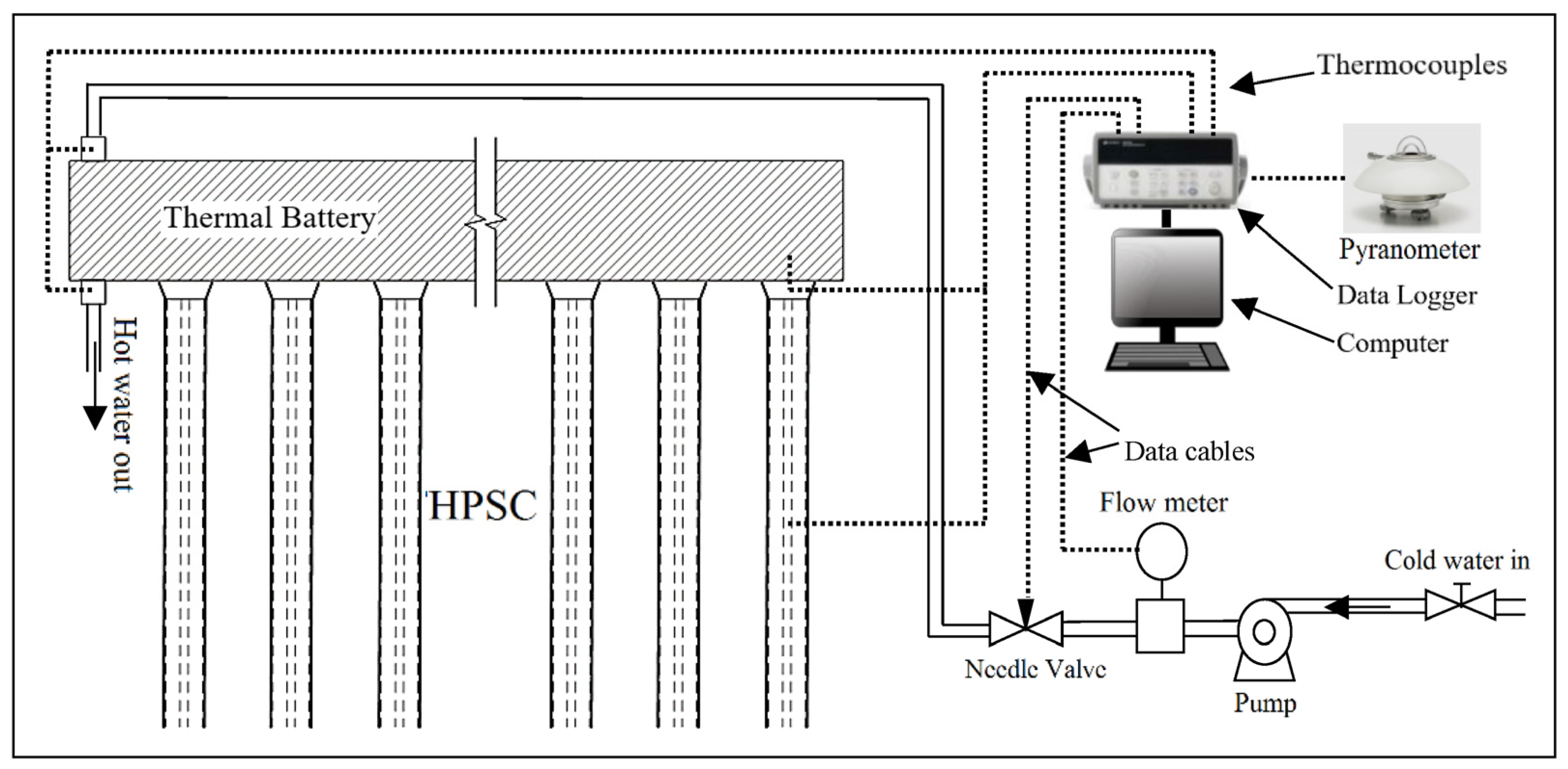
2. System Description
3. Uncertainty Analysis
4. Results and Discussions
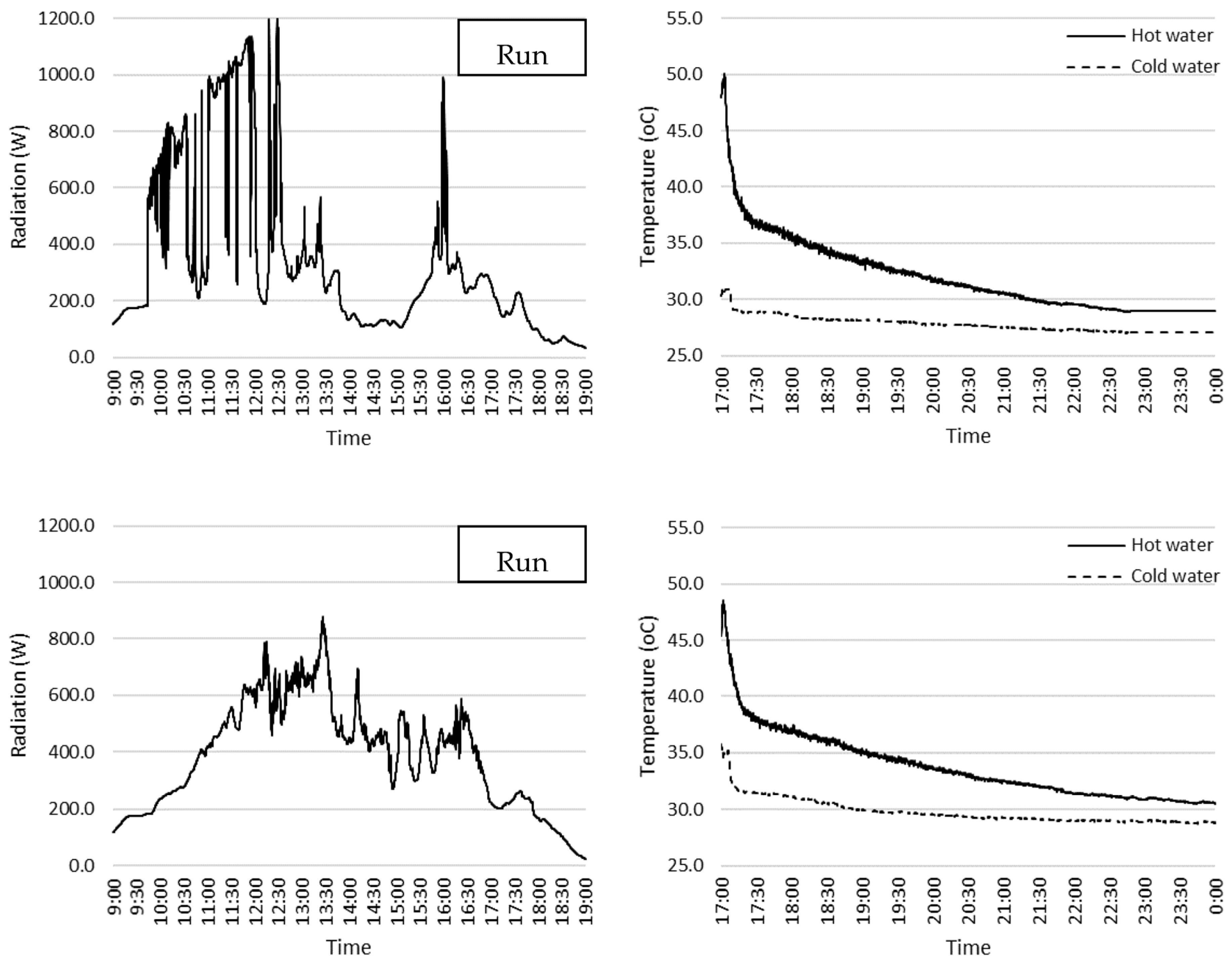
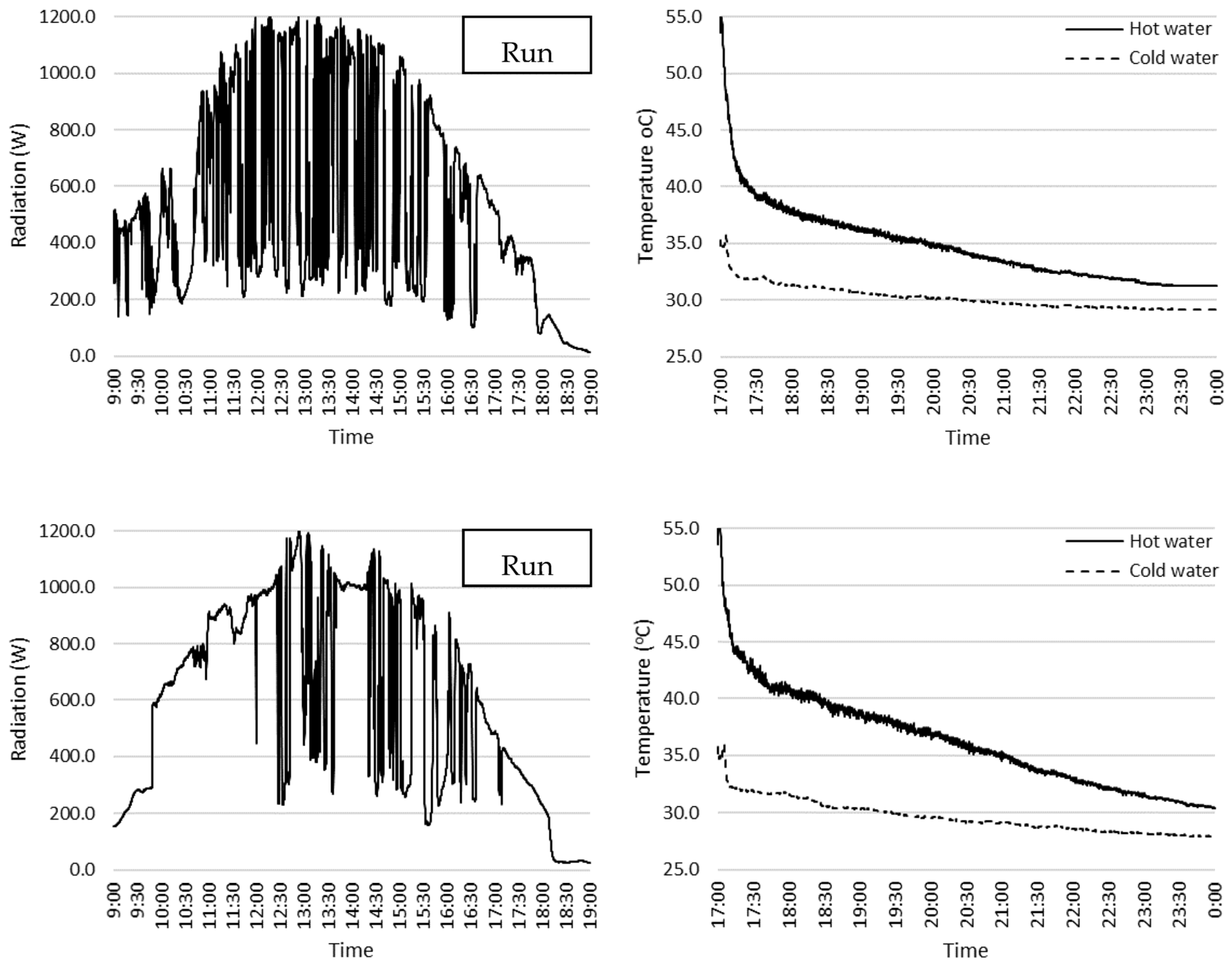
4.1. Mode 1 (Charging-Discharging Mode)
Efficiency of the Thermal Battery
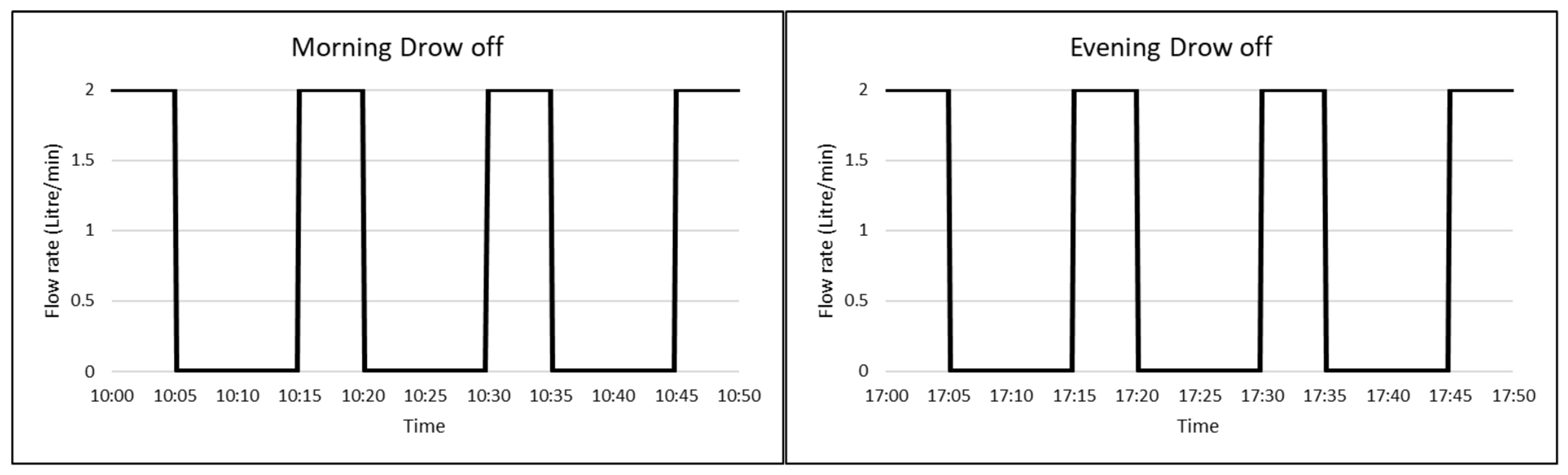
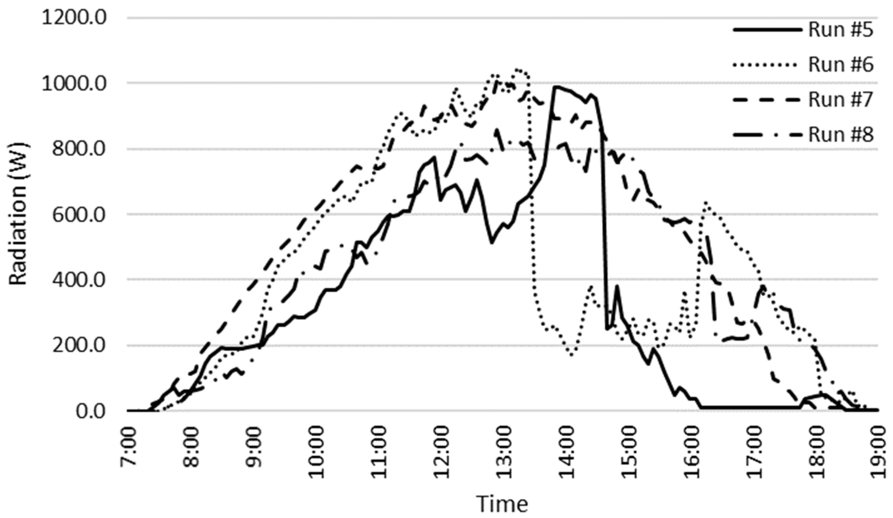
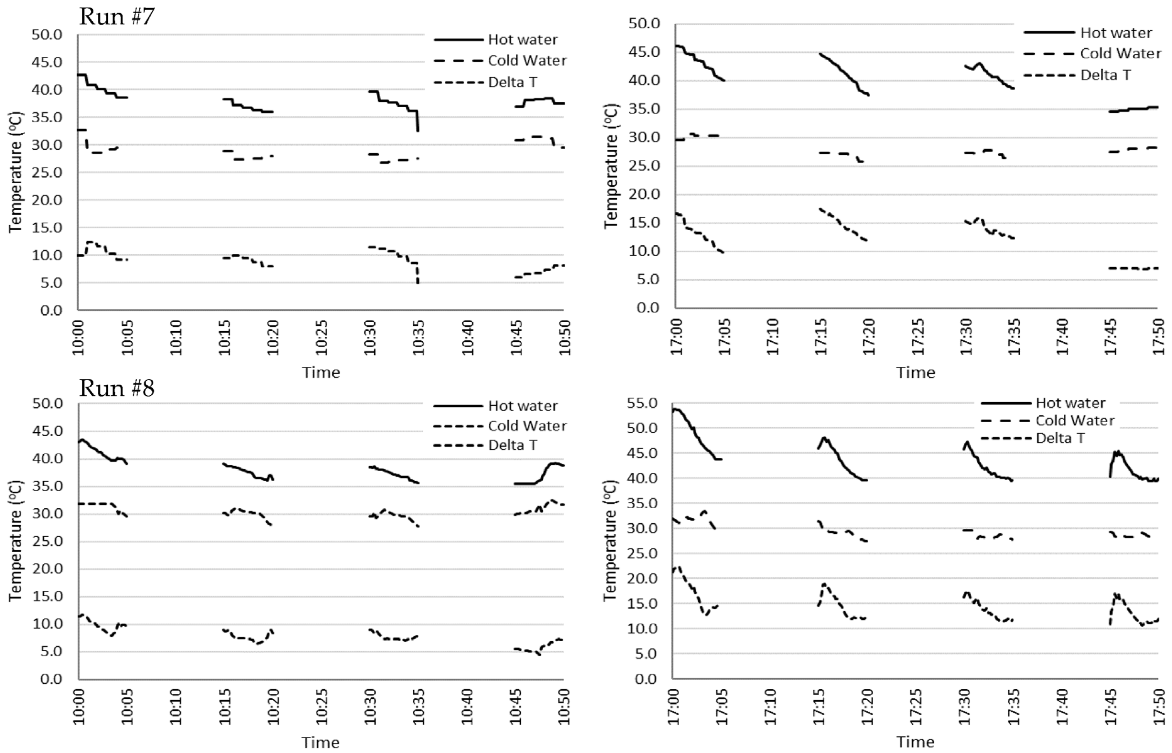
4.2. Mode 2 (Periodic Draw-Off Mode)
Hot Water Volume
5. Conclusions
- The efficiency of the thermal battery is in the range of 44% on low solar intensity days and 56% on high solar intensity days.
- Considering the solar radiation fluctuation and uncertainty of the results, the overall efficiency of the thermal battery is 50% ± 9.3%.
- The thermal battery can warm up the cold water higher than the operating temperature on a sunny day (more than 120 L per day at 38 °C).
- The thermal battery required an auxiliary heater to warm up the outlet water to the operating temperature on cloudy or rainy days.
- This configuration does not need any separate hot water storage tank.
- There is no need for a water pump to increase the hot water pressure.
- The effect of layering of hot water (stratification effect) in the hot water tank is removed.
- Hot water can be produced immediately according to the demand of the end-user.
- The thermal battery is connected to the solar collector. Removing the hot water tank, extra pipe, and water pump makes the system compact, cheaper, and easy to install.
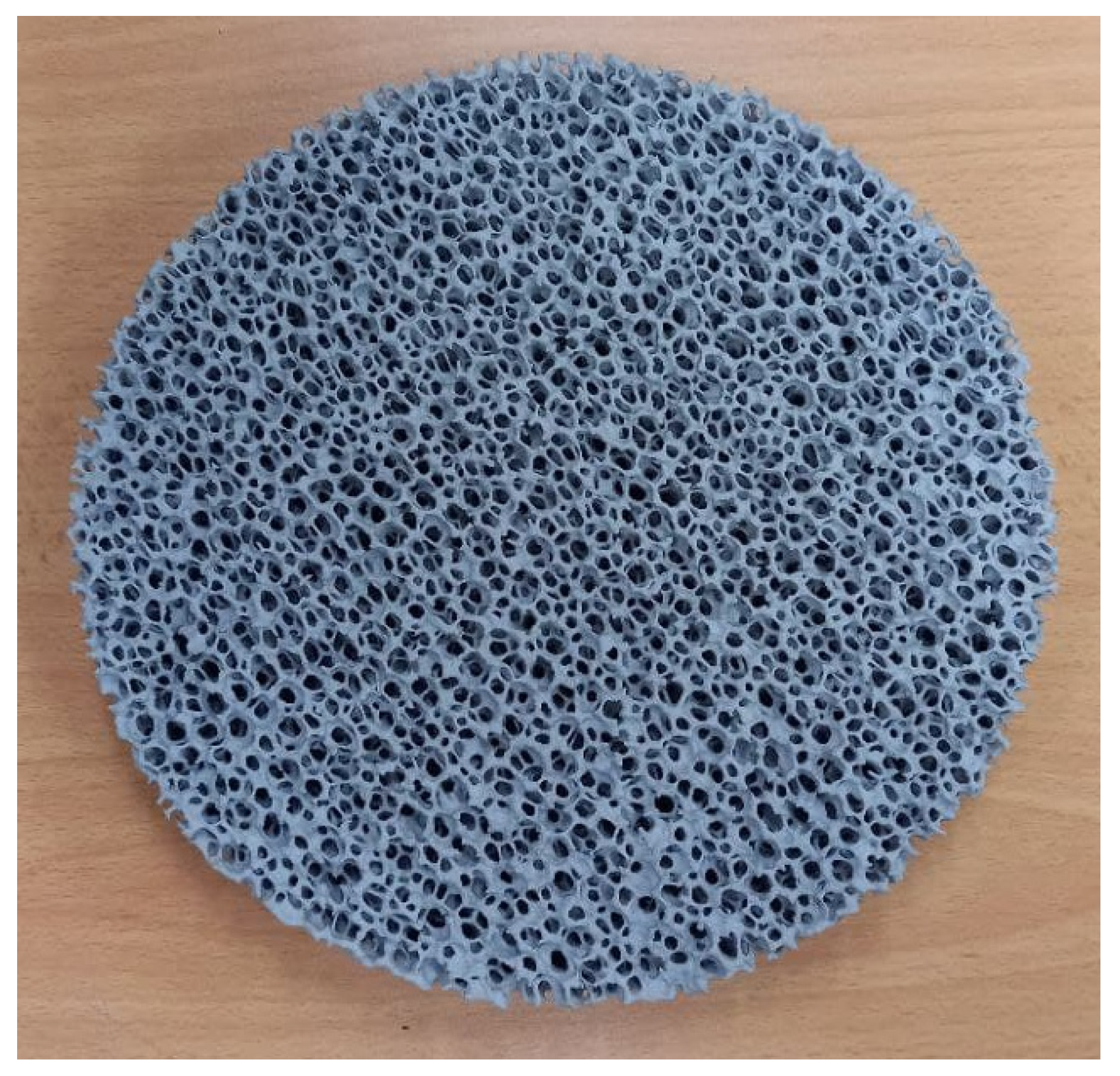
- Using porous media provides better heat distribution in the PCM.
Author Contributions
Funding
Institutional Review Board Statement
Informed Consent Statement
Data Availability Statement
Acknowledgments
Conflicts of Interest
Nomenclature
| Symbols | |
| LHS tank Surface area | |
| Solar collector apparatus area | |
| Heat capacity of water | |
| Function | |
| Molten PCM fraction | |
| incident radiation | |
| Latent heat energy | |
| Water mass flowrate | |
| Total mass of hot water | |
| Number of the fins | |
| Number of HPSCs | |
| Heat loss from the tank | |
| Heat storage | |
| Heat transfer to the cold water | |
| hot water volume in operating temperature | |
| Absorbed solar energy | |
| Temperature | |
| Greek | |
| Uncertainty measurement | |
| Efficiency | |
| Abbreviations | |
| ETHPSC | Evacuated tube HP solar collector |
| HP | Heat pipe |
| HPA | Heat pipe adiabatic |
| HPC | Heat pipe condenser |
| HPE | Heat pipe evaporator |
| HPSC | Heat pipe solar collector |
| HTF | Heat transfer fluid |
| LHTES | Latent heat thermal energy storage |
| PCM | Phase change materials |
| PV | Photovoltaic |
| SHIP | Solar heat industrial processes |
| SWH | Solar water heating |
| TC | Thermocouple |
References
- Naghavi, M.; Metselaar, H.; Ang, B.; Zamiri, G.; Esmailzadeh, A.; Nasiri-Tabrizi, B. A critical assessment on synergistic improvement in PCM based thermal batteries. Renew. Sustain. Energy Rev. 2021, 135, 110259. [Google Scholar] [CrossRef]
- Kaygusuz, K. Experimental and theoretical investigation of latent heat storage for water based solar heating systems. Energy Convers. Manag. 1995, 36, 315–323. [Google Scholar] [CrossRef]
- Amagour, M.E.H.; Bennajah, M.; Rachek, A. Numerical investigation and experimental validation of the thermal performance enhancement of a compact finned-tube heat exchanger for efficient latent heat thermal energy storage. J. Clean. Prod. 2021, 280, 124238. [Google Scholar] [CrossRef]
- Alptekin, E.; Ezan, M.A. A systematic assessment on a solar collector integrated packed-bed single/multi-layered latent heat thermal energy storage system. J. Energy Storage 2021, 37, 102410. [Google Scholar] [CrossRef]
- Pawar, V.R.; Sobhansarbandi, S. CFD modeling of a thermal energy storage based heat pipe evacuated tube solar collector. J. Energy Storage 2020, 30, 101528. [Google Scholar] [CrossRef]
- Naghavi, M.; Ong, K.; Badruddin, I.; Mehrali, M.; Metselaar, H. Thermal performance of a compact design heat pipe solar collector with latent heat storage in charging/discharging modes. Energy 2017, 127, 101–115. [Google Scholar] [CrossRef]
- Silakhori, M.; Naghavi, M.S.; Metselaar, H.S.C.; Mahlia, T.M.I.; Fauzi, H.; Mehrali, M. Accelerated Thermal Cycling Test of Microencapsulated Paraffin Wax/Polyaniline Made by Simple Preparation Method for Solar Thermal Energy Storage. Materials 2013, 6, 1608–1620. [Google Scholar] [CrossRef] [Green Version]
- Mehrali, M.; Latibari, S.T.; Mehrali, M.; Mahlia, T.M.I.; Metselaar, H.S.C.; Naghavi, M.S.; Sadeghinezhad, E.; Akhiani, A.R. Preparation and characterization of palmitic acid/graphene nanoplatelets composite with remarkable thermal conductivity as a novel shape-stabilized phase change material. Appl. Therm. Eng. 2013, 61, 633–640. [Google Scholar] [CrossRef]
- Yang, X.; Yu, J.; Guo, Z.; Jin, L.; He, Y.-L. Role of porous metal foam on the heat transfer enhancement for a thermal energy storage tube. Appl. Energy 2019, 239, 142–156. [Google Scholar] [CrossRef]
- Rabbi, J.; Asif, M. A numerical study on effects of heat transfer fluids, copper mesh in packed bed and porosity, on charging time of paraffin based packed bed thermal energy storage. Energy Storage 2021, 3, e254. [Google Scholar] [CrossRef]
- Tiari, S.; Mahdavi, M. Computational study of a latent heat thermal energy storage system enhanced by highly conductive metal foams and heat pipes. J. Therm. Anal. Calorim. 2020, 141, 1741–1751. [Google Scholar] [CrossRef]
- Chen, S.-B.; Saleem, S.; Alghamdi, M.N.; Nisar, K.S.; Arsalanloo, A.; Issakhov, A.; Xia, W.-F. Combined effect of using porous media and nano-particle on melting performance of PCM filled enclosure with triangular double fins. Case Stud. Therm. Eng. 2021, 25, 100939. [Google Scholar] [CrossRef]
- Naghavi, M.; Ang, B.; Rahmanian, B.; Bazri, S.; Mahmoodian, R.; Metselaar, H. On-demand dynamic performance of a thermal battery in tankless domestic solar water heating in the tropical region. Appl. Therm. Eng. 2020, 167, 114790. [Google Scholar] [CrossRef]
- Naghavi, M.; Ong, K.; Badruddin, I.; Mehrali, M.; Silakhori, M.; Metselaar, H. Theoretical model of an evacuated tube heat pipe solar collector integrated with phase change material. Energy 2015, 91, 911–924. [Google Scholar] [CrossRef]
- Fadaeenejad, M.; Mohd Radzi, M.A.; Fadaeenejad, M.; Zarif, M.; Gandomi, Z. Optimization and comparison analysis for application of PV panels in three villages. Energy Sci. Eng. 2015, 3, 145–152. [Google Scholar] [CrossRef]
- Saadatian, O.; Sopian, K.; Elhab, B.; Ruslan, M.H.; Asim, N. Optimal solar panels’ tilt angles and orientations in Kuala Lumpur, Malaysia. In Proceedings of the 1st WSEAS International Conference on Energy and Environment Technologies and Equipment (EEETE’12), London, UK, 27–29 October 2017; pp. 100–107. [Google Scholar]
- Khatib, T.; Mohamed, A.; Sopian, K. Optimization of a PV/wind micro-grid for rural housing electrification using a hybrid iterative/genetic algorithm: Case study of Kuala Terengganu, Malaysia. Energy Build. 2012, 47, 321–331. [Google Scholar] [CrossRef]
- Daut, I.; Irwanto, M.; Irwan, Y.M.; Gomesh, N.; Ahmad, N.S. Clear sky global solar irradiance on tilt angles of photovoltaic module in Perlis, Northern Malaysia. In Proceedings of the International Conference on Electrical, Control and Computer Engineering (INECCE), Kuantan, Malaysia, 21–22 June 2011; IEEE: Piscataway, NJ, USA, 2011. [Google Scholar]
- Elhassan, Z.A.M.; Zain, M.F.M.; Sopian, K.; Awadalla, A. Output Energy of Photovoltaic Module Directed at Optimum Slope Angle in Kuala Lumpur, Malaysia. Res. J. Appl. Sci. 2011, 6, 104–109. [Google Scholar] [CrossRef]
- Ong, K.S.; Tong, W.L.; Sheriwati, S.; Low, T.H. System performance of heat pipe solar water heaters. In Proceedings of the 10th International Heat Pipe Symposium, New Taipei City, Taiwan, 6–9 November 2011; Tamkang University Press: New Taipei City, Taiwan, 2011. [Google Scholar]
- Loh, C.; Harris, E.; Chou, D. Comparative study of heat pipes performances in different orientations. In Proceedings of the Semiconductor Thermal Measurement and Management IEEE Twenty First Annual IEEE Symposium, San Jose, CA, USA, 15–17 March 2005; IEEE: Piscataway, NJ, USA, 2005. [Google Scholar]
- Horbaniuc, B.; Dumitrascu, G.; Popescu, A. Mathematical models for the study of solidification within a longitudinally finned heat pipe latent heat thermal storage system. Energy Convers. Manag. 1999, 40, 1765–1774. [Google Scholar] [CrossRef]
- Liu, Z.; Wang, Z.; Ma, C. An experimental study on the heat transfer characteristics of a heat pipe heat exchanger with latent heat storage. Part II: Simultaneous charging/discharging modes. Energy Convers. Manag. 2006, 47, 967–991. [Google Scholar] [CrossRef]
- Liu, X.; Fang, G.; Chen, Z. Dynamic charging characteristics modeling of heat storage device with heat pipe. Appl. Therm. Eng. 2011, 31, 2902–2908. [Google Scholar] [CrossRef]
- Hussein, H.; El-Ghetany, H.; Nada, S. Experimental investigation of novel indirect solar cooker with indoor PCM thermal storage and cooking unit. Energy Convers. Manag. 2008, 49, 2237–2246. [Google Scholar] [CrossRef]
- Karthick, R.; Manivannan, A. Thermel energy storage in solar water heater using phase change material. Int. Dly. J. Discov. 2015, 37, 28–36. [Google Scholar]
- Wang, Z.; Qiu, F.; Yang, W.; Zhao, X. Applications of solar water heating system with phase change material. Renew. Sustain. Energy Rev. 2015, 52, 645–652. [Google Scholar] [CrossRef]
- Technical Data Silicon Carbide. 2021. Available online: https://global.kyocera.com/prdct/fc/list/material/silicon_carbide/silicon_carbide.html (accessed on 15 October 2021).
- Chong, W.; Naghavi, M.; Poh, S.; Mahlia, T.M.I.; Pan, K. Techno-economic analysis of a wind–solar hybrid renewable energy system with rainwater collection feature for urban high-rise application. Appl. Energy 2011, 88, 4067–4077. [Google Scholar] [CrossRef]
- Li, F.-F.; Diao, Y.-H.; Zhao, Y.-H.; Zhu, T.-T.; Liu, J. Experimental study on the thermal performance of a new type of thermal energy storage based on flat micro-heat pipe array. Energy Convers. Manag. 2016, 112, 395–403. [Google Scholar] [CrossRef]
- Faghri, A. Heat Pipes: Review, Opportunities and Challenges. Front. Heat Pipes (FHP) 2014, 5. [Google Scholar] [CrossRef] [Green Version]
- Bergman, T.L.; Incropera, F.P. Introduction to Heat Transfer; Wiley: New York, NY, USA, 2011. [Google Scholar]
- JKR. Standard Specification for Building Works. In Water Meter; Jabatan Kerja Jaya: Kuala Lumpur, Malaysia, 2004. [Google Scholar]
- Thermostatic Mixing Valve Manufacturers Association. Recommended Code of Practice for Safe Water Temperatures; BEAMA: London, UK, 2013. [Google Scholar]
- Armstrong, P.; Ager, D.; Thompson, I.; McCulloch, M. Domestic hot water storage: Balancing thermal and sanitary performance. Energy Policy 2014, 68, 334–339. [Google Scholar] [CrossRef]


| Item | Value (mm) |
|---|---|
| ETHPSC outer tube diameter | 58 |
| ETHPSC inner tube diameter | 52 |
| Distance between 2 ETHPSCs | 142 |
| HPE length | 1675 |
| HP adiabatic length | 30 |
| HPC length | 70 |
| Thermal battery diameter | 200 |
| Thermal battery length | 1850 |
| Thermal battery wall thickness | 2 |
| Water pipe outer diameter | 27 |
| Water pipe length (Both U-shape pipes) | ~7400 |
| Property | Value | Unit |
|---|---|---|
| Melting point | 53–57 (~55) | °C |
| Density solid/liquid at 15/70 °C | 990/916 | kg/m3 |
| Thermal conductivity of solid/liquid | 0.349/0.167 | W/m·K |
| Specific heat solid/liquid | 2.76/2.48 | kJ/kg·K |
| Heat storage capacity | 164 | kJ/kg |
| Property | Value | Unit |
|---|---|---|
| Diameter | 200 | mm |
| Thickness | 30 | mm |
| PPI | 10 | - |
| Porosity | ~90 | % |
| Thermal conductivity (100 °C) [28] | ~56 | W/(m·K) |
| Run No. | Solar Intensity Category | Weather Conditions in Morning, Noon, Afternoon |
|---|---|---|
| #1 | Low | cloudy, cloudy, cloudy |
| #2 | Low | sunny, rainy, rainy |
| #3 | High | sunny, sunny, sunny |
| #4 | High | sunny, sunny, sunny |
| Runs No. | Daily Radiation (MJ/m2) | Daily Total Solar Radiation (MJ) | Storable Daily Solar Radiation (MJ) | Total Heat Transfer to Water (MJ) | Efficiency of Thermal Battery (%) | Efficiency of System (%) |
|---|---|---|---|---|---|---|
| #1 | 13.9 | 24.6 | 13.3 | 5.8 | 44% | 24% |
| #2 | 12.3 | 21.8 | 11.8 | 5.5 | 47% | 25% |
| #3 | 18.6 | 33.0 | 17.9 | 7.6 | 42% | 23% |
| #4 | 21.4 | 37.9 | 20.5 | 11.4 | 56% | 30% |
| Run No. | Recorded Daily Solar Radiation (Ir/m2) | Total Daily Solar Radiation (It/Day) | Absorbable Daily Solar Radiation (Ia/Day) | Hot Water Volume in 38 °C (L/Day) |
|---|---|---|---|---|
| #5 | 13.6 | 24.1 | 13.1 | 0.0 |
| #6 | 15.9 | 28.2 | 15.3 | 0.0 |
| #7 | 22.1 | 39.2 | 21.2 | 197.1 |
| #8 | 20.1 | 35.5 | 19.2 | 130.8 |
Disclaimer/Publisher’s Note: The statements, opinions and data contained in all publications are solely those of the individual author(s) and contributor(s) and not of MDPI and/or the editor(s). MDPI and/or the editor(s) disclaim responsibility for any injury to people or property resulting from any ideas, methods, instructions or products referred to in the content. |
© 2023 by the authors. Licensee MDPI, Basel, Switzerland. This article is an open access article distributed under the terms and conditions of the Creative Commons Attribution (CC BY) license (https://creativecommons.org/licenses/by/4.0/).
Share and Cite
Naghavi Sanjani, M.S.; Silakhori, M.; Ang, B.C.; Simon Cornelis Metselaar, H.; Mousavi Gazafroudi, S.M.; Noorollahi, Y. Experimental Investigation on Solar Water Heater Integrated with Thermal Battery Using Phase Change Material and Porous Media. Sustainability 2023, 15, 6439. https://doi.org/10.3390/su15086439
Naghavi Sanjani MS, Silakhori M, Ang BC, Simon Cornelis Metselaar H, Mousavi Gazafroudi SM, Noorollahi Y. Experimental Investigation on Solar Water Heater Integrated with Thermal Battery Using Phase Change Material and Porous Media. Sustainability. 2023; 15(8):6439. https://doi.org/10.3390/su15086439
Chicago/Turabian StyleNaghavi Sanjani, Mohammad Sajad, Mahyar Silakhori, Bee Chin Ang, Hendrik Simon Cornelis Metselaar, Sayed Mohammad Mousavi Gazafroudi, and Younes Noorollahi. 2023. "Experimental Investigation on Solar Water Heater Integrated with Thermal Battery Using Phase Change Material and Porous Media" Sustainability 15, no. 8: 6439. https://doi.org/10.3390/su15086439