Article

Study of Heat Transfer Characteristics and Economic Analysis of a Closed Deep Coaxial Geothermal Heat Exchanger Retrofitted from an Abandoned Oil Well

1
Faculty of Thermal Energy Engineering, Shandong Jianzhu University, Jinan 250101, China
2
Faculty of Construction, Hong Kong Polytechnic University, Hong Kong SAR 999077, China
*
Author to whom correspondence should be addressed.
Sustainability 2024, 16(4), 1603; https://doi.org/10.3390/su16041603
Submission received: 31 December 2023 / Revised: 9 February 2024 / Accepted: 12 February 2024 / Published: 14 February 2024

Abstract

:
It is economical to transform abandoned oil/geothermal wells into closed deep geothermal heat exchangers with coaxial tubes. A numerical model of a coaxial geothermal heat exchanger (CGHE) with varying borehole diameters is established according to an abandoned well in Northern China. The finite difference method is adopted to solve the temperature distribution, and the accuracy of the model is validated with experimental data. Based on the existing structure of the abandoned well with different depths, the feasibility of its conversion into a deep CGHE is discussed, and this study uses the orthogonal experimental method to analyze the influence of four main factors and their significance level on the average heat extraction rate, with the heat extraction rate up to 422.18 kW in the optimal combination. This study also integrates with actual project considerations and conducts an economic analysis to determine the most appropriate circulation fluid flow rate. The results highlight the key factors on the heat transfer performance of the CGHE, with the inlet water temperature to the CGHE being the most significant, followed by the configuration of the CGHE retrofitted from abandoned. From the economic perspective, given that the CGHE in this study is retrofitted from the abandoned oil Wells, the drilling cost can be reduced by up to CNY 1800 thousand, and the flow rate design of 35 m3/h is the optimal choice, ensuring a cost-effective system operation while meeting the operational requirements of the deep CGHE.

1. Introduction

It is estimated that coal remains the primary energy source for 92% of space heating systems in China [1], precipitating a substantial contribution to greenhouse gas emissions. Consequently, it is necessary to utilize renewable energy for building heating to reduce coal consumption and alleviate air pollution. Geothermal energy has shown significant potential in space heating because of its environmental friendliness and reduced energy consumption [2,3]. The installed capacity of geothermal heat pumps for space heating and cooling exceeds 26,450 MWt in China by the end of 2020 [4].
Deep geothermal space heating systems have recently aroused growing interest in academic and engineering fields because of their enhanced thermal capacities and decreased installation space requirements in contrast to shallow geothermal systems [5,6]. The most crucial component of a deep geothermal heating system is the deep coaxial geothermal heat exchanger (CGHE), also known as coaxial borehole heat exchanger or wellbore heat exchanger. Nevertheless, drilling a borehole incurs the most significant financial investment of any geothermal system, accounting for up to 70% of the total investment costs on average, and therefore makes these systems economically unprofitable [7]. This prompts the desire to explore alternative solutions for efficient and economical acquisition of geothermal energy.
In recent years, retrofitting an abandoned oil well into a CGHE has emerged as a promising method to enhance geothermal energy applications. For instance, Morita et al. [8,9] reported the pioneering CGHE experiment in an abandoned well on the island of Hawaii. Following this, Kohl et al. [10,11] reported the performance of a CGHE at Weissbad and Weggis, Switzerland. Abandoned oil and gas wells (AOGWs) with high bottom-hole temperatures contain abundant geothermal energy. This energy can be harnessed by retrofitting these wells into novel geothermal systems for various uses without the need for costly drilling [12]. Furthermore, Cheng et al. [13,14] successfully employed the organic Rankine cycle to exploit the geothermal energy of abandoned oil wells. They also presented a novel method to enhance geothermal utilization efficiency through the development of thermal reservoirs.
Previous studies have demonstrated the feasibility of harvesting geothermal energy from existing abandoned oil and gas wells. A wide range of wells across different countries have been covered, such as horizontal wells [15], enhanced geothermal systems (EGS) and low-temperature deep borehole heat exchangers (DBHE) in California [16], U-tube heat exchanger located in Southern Iran [17], and double-pipe geothermal and Jachowka K-2 [18] heat exchanger in the Persian Gulf [19]. Some studies also proposed mathematical models to analyze key factors affecting heat outputs from CGHEs. A software package (ANSYS 2019) was developed based on the finite difference method for thermal analysis of a CGHE [20]. An unsteady-state heat transfer model [21] was also established for a deep CGHE and validated with experimental data. A transient 2D finite volume method (FVM) was applied to solve the thermal interference under seasonal effects and dynamic heat flux within a vertical coaxial borehole heat exchangers field [22]. In consideration of well kick occurrences during the drilling process, the models were solved using the fully implicit finite difference method coupled with the clustering method [23].
For the performance optimization of the CGHE, Bu et al. [24] developed mathematical models to investigate the heat exchange between fluid and rocks. Based on the models, they also examined the effects of critical parameters and determined their optimal values. Yekoladio et al. [25] identified the optimal mass flow of geothermal fluid under minimum pumping power and maximum extracted heat energy. Beier et al. [26] characterized and analyzed the vertical temperature profiles of the working fluid of a CGHE. Nian et al. [27] developed a building and CGHE integrated model that comprehensively takes the heat transfer of wellbores, system formation, and building thermal loads into consideration. This model is successfully used to examine critical system performance parameters, including the production of geothermal energy, room temperature, and outlet water temperature.
Currently, the number of AOGWs worldwide has reached approximately 30 million [16,27]. In addition, regions with favorable geothermal parameters are inherently rich in geothermal energy [7]. The conversion of those petroleum wells into geothermal heat exchangers can substantially reduce the investment costs of borehole drilling [16,24] and enhance the utilization of geothermal resources, while also mitigating environmental risks [28]. Therefore, repurposing old petroleum boreholes for geothermal energy extraction is highly desirable in the pursuit of global carbon neutrality.
Despite the extensive research, a comprehensive performance analysis of a CGHE retrofitted from AOGW, particularly in terms of varied borehole diameters, remains lacking. There is also a lack of a computational model for the CGHE with different diameters Most existing studies merely focus on retrofitting processes, ignoring an in-depth examination of factors that affect the heat extraction performance of such retrofitted heat exchangers. Moreover, there is a notable scarcity of insightful research on optimizing critical parameters during the retrofitting process and analyzing the economic performance of these systems. Given these research gaps, this study aims to develop a numerical heat transfer model of the retrofitted CGHE with varied outer pipe diameters based on the finite difference method (FDM) [20]. Based on the developed CGHE model, the influence of four critical factors on the thermal performance of CGHE is evaluated. In addition, the optimal flow rate of CGHE is also investigated from an economic standpoint. The findings of this study can further enhance the adoption of deep CGHE from abandoned oil wells and extend the utilization of deep geothermal energy.

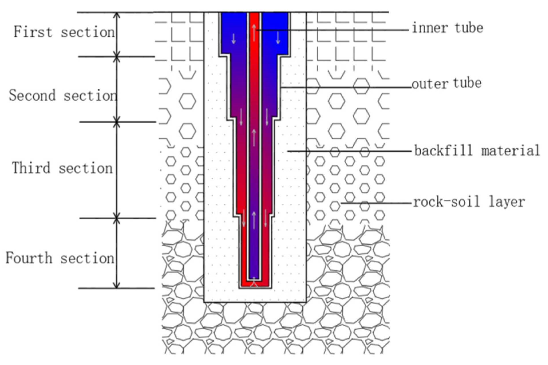
2. Abandoned Oil Well Structure and Working Principles of a CGHE

The oil well usually consists of a steel pipe with varying pipe diameters along the borehole depth. The drilling process and equipment used for oil well engineering are almost identical to those used for CGHE, which makes retrofitting the oil well into CGHE possible. In this study, the abandoned well, which will be retrofitted to CGHE with coaxial tubes, refers to an oil well that no longer has economic potential after several years of oil production. Compared with a conventional CGHE, the main distinction of the retrofitted CGHE derived from an abandoned well lies in its decreasing diameter of the outer pipe along the borehole depth. Thus, developing a CGHE with varied outer pipe diameters for different depth regions is critical to this transformation. There are various types of retrofitted CGHE, and currently, the three-section CGHE and four-section CGHE are the most commonly used types and are more suitable for heat extraction. Figure 1 describes a cross-section structure of the retrofitted CGHE with four sections along the borehole depth. As shown, the diameter of the outer pipe decreases along the depth, while the diameter of the inner pipe remains constant.
Due to the high ground temperature, the deep CGHE is only used for heat extraction to provide space heating for buildings. Under heat extraction conditions, low-temperature water flows into the CGHE through the outer pipe. During this process, the circulating water is heated by the surrounding ground. As the water reaches the bottom of the CGHE, it reaches its highest temperature and flows into the inner pipe. One advantage of this system is that it operates as a closed circulation system, meaning that it does not extract groundwater directly during the heat extraction process, which can help protect the groundwater environment to some extent.

3. Development of Numerical Heat Transfer Model

3.1. Model Assumptions

To improve the calculation efficiency while maintaining the prediction accuracy, the following assumptions are adopted:
  • The thermal properties of ground, pipe, water, and backfilling material are dependent on their specific temperatures.
  • The properties of the ground are homogeneous in each ground layer.
  • The penetration of groundwater is neglected.
  • The lateral and bottom boundaries of the borehole model are set to be temperature constant.
  • The geothermal heat flux in the ground is assumed to be uniform and constant.

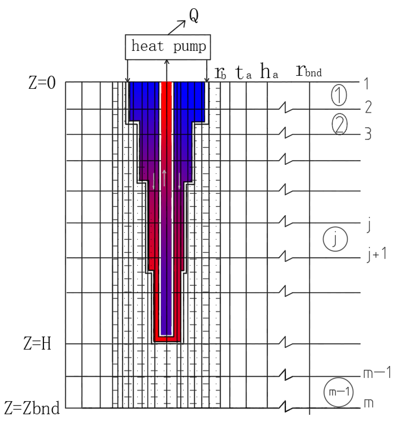
3.2. Initial and Boundary Conditions

The initial temperature of the ground has a uniform geothermal gradient along the depth direction in different ground layers. As the geothermal heat flux is assumed to be uniform and constant, the initial ground temperature at any depth in the stratum can be calculated by Equation (1) [20]:
t ( r , z ,   τ ) = t a + q g h a + j = 1 m 1 q g k j ( H j H j 1 ) + q g k m ( z H m 1 )
τ = 0 , H m 1 z H m , r b r r bnd
where ta is the ambient air temperature (°C), ha is the convective heat transfer coefficient at the ground surface, (W/(m2·K)), Hj is the bottom coordinate of the j-layer, qg is the geothermal heat flux (W/m2), k is the ground thermal conductivity (W/(m·K)); q g h a represents the temperature responses induced by qg at the ground surface, with a convective heat transfer coefficient of h a ; and q g k j represents the temperature responses induced by qg within the j-layer ground, with a conductive heat transfer coefficient of k j .
The bottom boundary of the whole calculation region is set far below the bottom of the borehole, with an extra distance of 200 m beneath the borehole bottom. As no thermal interference occurred at this bottom boundary, the temperature remains constant.
The heat convection boundary condition is set at the ground surface, which can be expressed by Equation (2) [20].
k t z = h a ( t t a ) , z = 0 , r b r r b n d , τ 0
Although the assumption of constant temperature slightly deviates from the actual conditions, which are influenced by variations in ground surface temperature, this impact can be ignored. Considering the drilling depth of more than 2000 m, the model does not need to introduce more complex boundary conditions.
For the two partial differential equations of fluid temperature distribution in the inner and outer tubes, it is considered that the initial temperature of the fluid in the tube is the same as that of the ground at the same depth, which can also be expressed by Equation (1).
The boundary conditions of the partial differential Equation (3) [20] of the flow direction of the tube is
{ t f 1 = t f 2 Q Mc ,   z = 0 t f 1 = t f 2 ,     z = H
where Q (W) is the total heat transfer rate of the CGHE, and c (J/(kg·K) is the specific heat capacity of the circulating fluid.

3.3. Heat Transfer Governing Equation

Based on the above assumptions, the heat transfer governing equations of the CGHE are described as follows. Since each layer of ground is axially symmetric, the heat transfer process of each layer of the ground can be regarded as a two-dimensional unsteady heat transfer in the cylindrical coordinate [20]:
1 a t τ = 1 r r ( r t r ) + 2 t z 2
In the case of heat extraction, the heat flux exchanged between the CGHE and ground peaks at the borehole wall and decreases radially outward. As a result, the ground temperature gradually decreases and can hardly be detected at the radial boundary. Considering heat transfer characteristics in the ground, the varied space steps in the radial direction are employed to improve the computing efficiency, as shown in Figure 2.
Thus, a new radial coordinate is adopted, which can be described as follows:
σ = l n r r 0 , r i + 1 r i = r 1 r 0 = e x p ( Δ σ ) = β
If we apply the new radial coordinate in the control Equation (6), it can be rewritten as follows:
1 a t τ = 1 r 2 2 t σ 2 + 2 t z 2
The flow pattern of the CGHE in this study is the fluid flowing down from the sandwich of two tubes and up from the inner tube. The energy differential equation of the fluid in the inner tube is
C 2 t f 2 τ = t f 2 t f 1 R 2 + C t f 2 z
The energy differential equation for the fluid in the outer tube is
C 1 t f 1 τ = t f 2 t f 1 R 2 + t b t f 1 R 1 C t f 1 z
where C = Mc is the heat capacity (J/(m·K)) of the circulating fluid; ρ f and c f are the density and specific heat capacity of the circulating fluid;   ρ f 1 and c f 1 are the density and specific heat of the outer pipe wall; and ρ f 2 and c f 2 are the density and specific heat of the inner pipe wall.
Considering the inner pipe and circulating water inside the inner pipe, the specific heat capacities should be calculated by
C 1 = π 4 ( d 1 i 2 d 2 o 2 ) ρ f c f + π 4 ( d 10 2 d 1 i 2 ) ρ 1 c 1 + π 4 ( d b 2 d 1 o 2 ) ρ g c g
C 2 = π 4 d 2 i 2 ρ f c f + π 4 ( d 2 o 2 d 2 i 2 ) ρ 2 c 2
where C1 is the per-length heat capacity of the outer channel, including the outer pipe, circulating water, and backfilling material (J/m·K); and C2 is the per-length heat capacity of the inner channel.
Since the model divides the CGHE into four sections, the thermal resistances of the four sections can be calculated according to different radial boundaries. The thermal resistances between the circulating water in the outer pipe and the borehole wall, R1, are given as follows:
R 1 = { 1 π d 11 i h 1 + 1 2 π k p 1 l n d 11 o d 11 i + 1 2 π k g l n d b d 21 i   0 < Z Z 1 1 π d 12 i h 1 + 1 2 π k p 1 l n d 12 o d 12 i + 1 2 π k g l n d b d 22 i   Z 1 < Z Z 2 1 π d 13 i h 1 + 1 2 π k p 1 l n d 13 o d 13 i + 1 2 π k g l n d b d 23 i   Z 2 < Z Z 3 1 π d 14 i h 1 + 1 2 π k p 1 l n d 14 o d 14 i + 1 2 π k g l n d b d 24 i   Z 3 < Z Z 4
R2 is the thermal resistance between the circulating water in the inner and outer pipes, which can be calculated by
R 2 = { 1 π d 21 i h 2 + 1 2 π k p 2 l n d 21 o d 2 i + 1 π d 21 o h 1   0 < Z Z 1 1 π d 22 i h 2 + 1 2 π k p 2 l n d 21 o d 2 i + 1 π d 22 o h 1   Z 1 < Z Z 2 1 π d 23 i h 2 + 1 2 π k p 2 l n d 23 o d 2 i + 1 π d 23 o h 1   Z 2 < Z Z 3 1 π d 24 i h 2 + 1 2 π k p 2 l n d 24 o d 2 i + 1 π d 24 o h 1   Z 3 < Z Z 4
where kg, kp1, and kp2 are the thermal conductivity of backfill material, outer pipe, and inner pipe, respectively; do and di represent the pipe’s outer diameter and inner diameter, respectively; and db represents the borehole diameter.
Moreover, h 1 and h 2 are the convective heat transfer coefficients of the annular pipe and inner pipe, which can be calculated by
h = Nu × k d
Nu is the dimensionless criterion number of the reaction on the strength of the heat transfer process, which can be obtained from [29,30]
Nu = 0.023 Re 0.8 Pr 0.333   Re 10 4
Nu = 1.86 Re 0.8 ( Re × Pr × d L i ) 0.333   Re 2200 ,   i = 1 , 2 , 3 , 4
Nu = 0.116 ( Re 0.667 125 ) Pr 0.333   Re > 2200
where L is the length of the borehole in each section, m; and Pr is the dimensionless number of the effect of reactive fluid property on heat transfer.
Re can be calculated by
Re = u × d ν
where u is the average section velocity, m/s; d is the equivalent diameter, m; and ν is the kinematic viscosity, m2/s.

3.4. Numerical Discretization

The heat transfer model for the deep CGHE can be considered a two-dimensional unsteady heat conduction problem with specific convective heat transfer boundary conditions on the borehole wall. This study employs the alternative direction finite difference method (ADFDM) [31]. The ADFDM combines the forward and backward FDM and uses them alternatively in adjacent time steps. This approach ensures that no more than three unknowns need to be solved for each numerical node, which significantly improves the calculation efficiency.
The model assumes that there is no influence from groundwater flow. Based on the geometric characteristics of the CGHE, the FDM is utilized to establish the computational grid division for the efficient simulation model of the heat exchanger in abandoned oil wells. The grid division is shown in Figure 2.
In the case of converting an abandoned well into a CGHE, there is a variation in the diameter of the outer pipe of the ground heat exchanger along the depth of the borehole. The calculation process differs from the conventional medium-depth CGHE, where the outer tube diameter remains constant. To address this, the fluid temperature in each section of the pipe with the same diameter needs to be calculated separately, as illustrated in Figure 3.
Based on the ADFDM, the numerical equations for fluid in inner and outer pipes can be obtained. It should be noted that the fluid in the pipe is assumed to be a one-dimensional model, indicating that the water temperature in the pipe on the horizontal level is uniform. The numerical equations of fluid in the outer pipe are as follows:
B 3 t f 2 , j p + 1 + ( 1 + B 1 + B 3 ) t f 1 , j p + 1 B 1 t 0 , j p + 1 = B 4 t f 1 , j 1 p + t f 1 , j p B 4 t f 1 , j + 1 p
B 4 t f 1 , j 1 p + 1 + t f 1 , j p + 1 B 4 t f 1 , j + 1 p + 1 = B 3 t f 2 , j p + ( 1 B 1 B 3 ) t f 1 , j p + B 1 t 0 , j p
where B 1 = Δ τ C 1 R 1 , B 3 = Δ τ C 1 R 2 , B 4 = C Δ τ 2 C 1 Δ z .
The numerical equations of fluid in the inner pipe are as follows:
B 2 t f 1 , j p + 1 + ( 1 + B 2 ) t f 2 , j p + 1 = B 5 ( t f 2 , j 1 p t f 2 , j + 1 p ) + t f 2 , j p
B 5 t f 2 , j 1 p + 1 + t f 2 , j p + 1 + B 5 t f 2 , j + 1 p + 1 = B 2 t f 1 , j p + ( 1 B 2 ) t f 2 , j p
where B 2 = Δ τ C 2 R 2 , B 5 = C Δ τ 2 C z Δ z .
The numerical equations of the ground are
B r t i 1 , j p + 1 + ( 1 + 2 B r ) t i + 1 , j p + 1 B r t i + 1 , j p + 1 = B z t i , j 1 p + ( 1 2 B z ) t i , j p B z t i , j + 1 p
B z t i , j 1 p + 1 + ( 1 + 2 B z ) t i , j p + 1 B z t i , j + 1 p + 1 = B r t i 1 , j p + ( 1 2 B r ) t i , j p + B r t i + 1 , j p
where B r = a Δ τ ( r Δ σ ) 2 , B z = a Δ τ ( Δ z ) 2 .

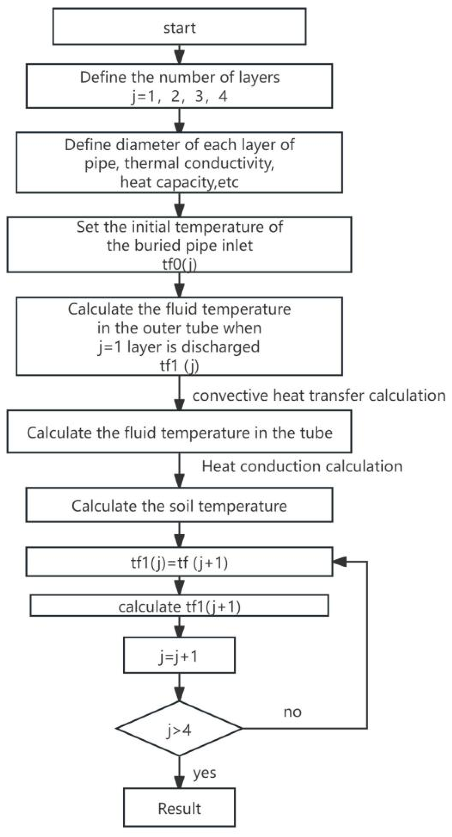
3.5. Equation Solving Algorithm

The complete difference equation can be broken down into several sets of second-order equations, and each set of algebraic equations has a tridiagonal coefficient matrix. These tridiagonal matrices satisfy the solution rule of the catch-up method. The tridiagonal linear algebraic equations can be expressed as follows [20]:
  b 1 t 1 + c 1 t 2 = d 1 a 2 t 1 + b 2 t 2 + c 2 t 3 = d 2 a i t i 1 + b i t i + c i t i + 1 = d i a n t n 1 + b n t n = d n }
Since the first equation contains only two unknowns, it can be written as
t 1 = U 1 t 2 + V 1
Therefore, when i = 1, the U 1 = c 1 b 1 . V 1 = d 1 b 1 .
Using this method, in turn, the general expression of the coefficient is
t i = U i t i + 1 + V i ,   i = 2 , 3 , , n 1
where U i = c i a i U i 1 + b i ; V 2 = d i a i V i 1 a i U i 1 + b i ; and i = 2, 3, …, n −1
It can be obtained according to the solution process of the catch-up method.
t n = d n a n V n 1 a n U n + 1 + b n
where U i = c i a i U i 1 + b i ; i = 2, 3, …; V i = d i a i V i 1 a i U i 1 + b i ; and i = 2, 3, …, n −1.

3.6. Model Validation

This study selected the experimental data from Xi’an’s non-interference geothermal heat supply project [32] to validate the proposed numerical model. In this project, the drilling depth is 2500 m, the average geothermal gradient is 0.0283 °C/m, the import flow rate of a single well is 13.97 m3/h, and the heating period is from 15 November to the 15 March. The inputs include the inlet fluid temperatures, specifications of the CGHE, thermal physical properties of the ground, ground temperature gradient, mass flow rate, and operation time. The output is the outlet water temperature, which was then used for model validation. In Reference [32], the maximum relative error between the simulated and measured outlet temperatures was 4.9%. It can be considered that the simulation results agree with the measured data.
In this study, the outlet water temperature of the project is simulated by the developed numerical model, with the same input parameters as Reference [32]. The comparison results among the numerical simulation results of this study and those of Reference [32] and the measured data are shown in Figure 4. It can be seen from Figure 4 that the proposed numerical result in this study follows a trend similar to both the measured data and the simulated data from Reference [32]. The maximum relative temperature difference of the numerical simulation data for the referred model versus the developed model in this manuscript is less than 5%. Therefore, the numerical model is considered reliable for further analysis of the performance of the CGHE.

4. Thermal Performance Analysis of the Retrofitted CGHE

4.1. Parameter Settings of the Retrofitted CGHE

The heat transfer performance of the deep CGHE is affected by factors such as the subsurface thermal properties, geometric parameters of the abandoned well, and operational parameters. In this study, an abandoned oil well located in Northern China is investigated as a case study, to be retrofitted into a CGHE for space heating. The abandoned well has four sections with different borehole diameters along the borehole depth. According to the onsite measurement, the average thermal properties of each section are determined by sample measurement, using the hot-disk thermal conductivity tester, and the obtained property data are listed in Table 1. The accuracy of the instrument for the thermal properties is within ±10%. The basic geometric parameters of the well are also listed in Table 1.
According to the ground temperature gradient tested in the field and the thermal conductivity of each rock layer, the geothermal heat flux can be approximated to be 0.058 W/m2, assuming a constant value. Other parameters are set as follows: the outer pipe is the steel pipe with a thermal conductivity of 43 W/(m·K), the circulating medium in the heat exchanger is water, the average temperature of the surface air is 15 °C, and the thermal conductivity of the backfill material is 1.5 W/(m·K). The inner and outer diameters of the inner pipe are set to be 110/90 mm.

4.2. Average Heat Extraction Rate in the Heating Season

The operating performance of the CGHE is related to the geometric and physical characteristics and, to a large extent, the working conditions. It is challenging to evaluate the heat transfer performance of CGHE comprehensively. Therefore, a quantitative index of the average heat extraction rate is defined to facilitate smooth communication between engineers and non-professionals. The average heat extraction rate of the CGHE refers to the mean heat extraction of a deep CGHE during the whole operation period, under specific operating conditions.
Q = Mc 0 t Δ T 1000 t
where 0 t Δ T is the sum of the difference between the inlet and outlet water temperatures at all times (°C); and t is time, h.
In this study, the particular condition refers to the fact that the inlet temperature of the CGHE system shall not be lower than 5 °C during the heating period, and 5 °C, 10 °C, 15 °C, and 20 °C are, respectively, used for the simulation.

4.3. Orthogonal Test Scheme Design and Test Results

Design parameters, geological conditions, operating conditions, and other factors will significantly impact the heat transfer performance of the CGHE. Especially for abandoned oil wells, many different transformation schemes will influence the value of the average heat extraction rate. The major difference between the abandoned well and the conventional CGHE is the varied outer pipe diameter, along the borehole depth. The smaller diameter of the fourth section leads to increased flow resistance, so whether to consider the fourth section as the heat exchange section needs comprehensive consideration. In this study, four retrofitted configurations of CGHE are considered, as shown in Table 2. It is noticed that the constant do is selected to be the diameter of the fourth section. Therefore, this study focuses on the impact of four main factors on heat extraction, namely the configuration of the rebuilt abandoned oil well, the inlet temperature, the mass flow rate, and the internal pipe thermal conductivity.
The orthogonal test is thus employed to analyze the influence parameters of the average heat extraction rate [33]. The orthogonal test method is widely used in scientific research because of its high efficiency and cost-effectiveness. It is necessary to clarify the significance of the influence of the factors.
The total influence factors of the orthogonal test are 4, and the level number of each factor is set to 4. The orthogonal test table, L16(44), is selected according to the factor level. The test scheme and test solution results corresponding to the level values of each factor are shown in Table 2 and Table 3, and the average heat extraction is set as the target parameter.

4.4. Analysis of Orthogonal Test Results

In the orthogonal test method, a certain factor may cause all the differences in the target parameters when only considering its influence. The factor which causes the most significant change in the average heat extraction rate is considered to be the main influencing factor. The calculation formula is as follows:
n i = 1 s n = 1 s y n
R = max ( n i ) min ( n i )
where ni is the arithmetic average of orthogonal test results when the level i is taken for the column factors; s is the number of tests for these factors under level i; yn is the index value of the k test; and R is the range value in this column.
The average heat extraction rate range analysis of the CGHE in abandoned well reconstruction is shown in Table 4.
The range analysis shows that the configurations of CGHEs retrofitted from abandoned oil wells, inlet temperature, mass flow rate, and inner tube thermal conductivity are 43.9, 124, 22.7, and 12.5, respectively. Therefore, the significance of each factor in affecting the heat transfer performance of the CGHE is listed as follows: inlet water temperature > configuration of CGHE retrofitted from abandoned oil wells > flow rate > inner tube thermal conductivity.
As Figure 5 shows, the average heat extraction rate increases with higher flow rates. However, the average heat extraction rate decreases as the inlet temperature rises, which is attributed to the smaller temperature difference between the circulating fluid and the surrounding ground. Moreover, it also shows that the thermal insulation performance of the inner tube plays a vital role in preventing the thermal short circuit phenomenon between the inner tube and the outer tube and also improving the heat extraction performance of the system.

5. Case Study and Economic Analysis

In this section, the economic analysis is performed on the retrofitted CGHE from the abandoned oil well, aiming to disclose its practical feasibility and popularization potential of actual applications.

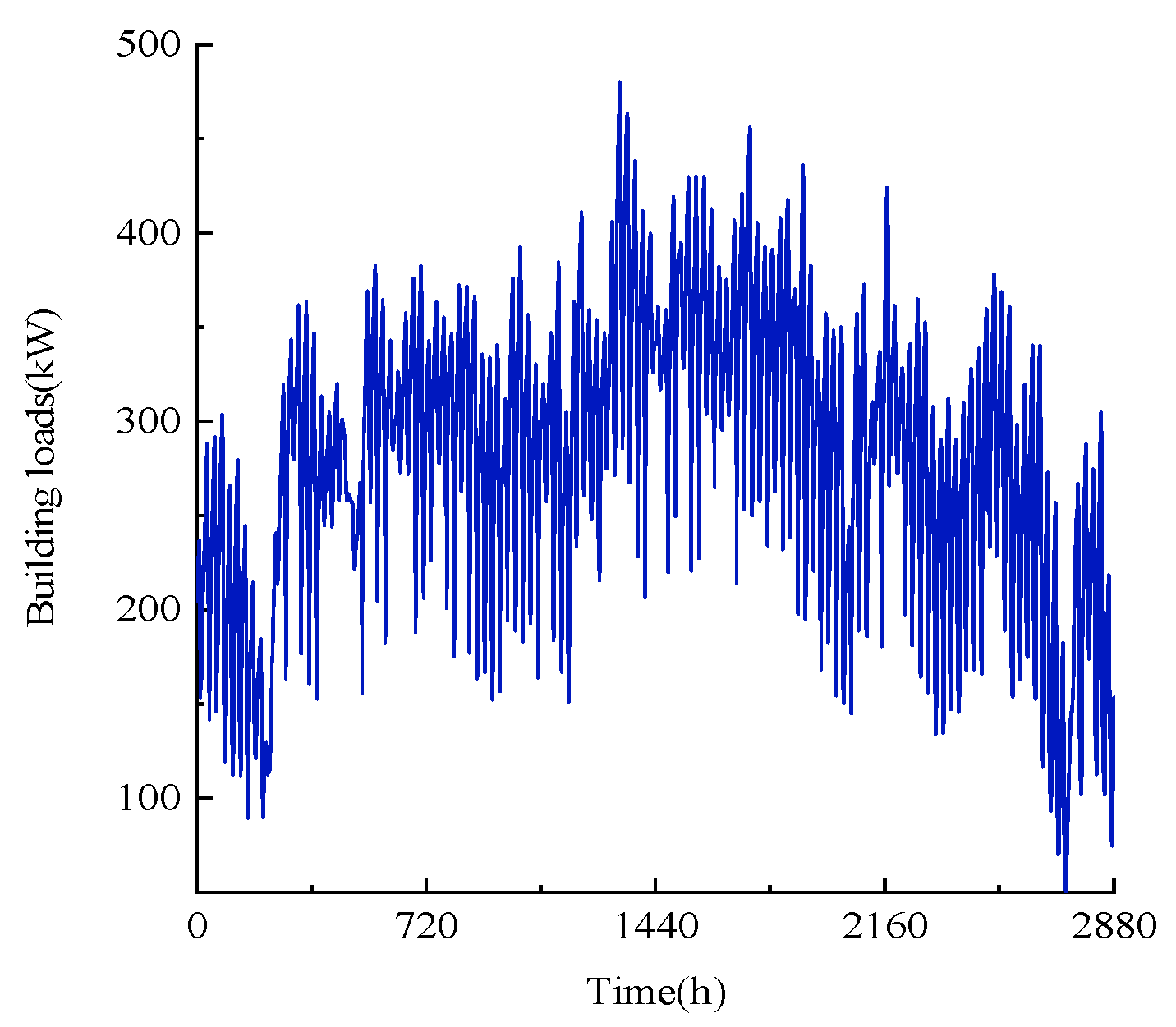
5.1. Actual Operation of the Ground Source Heat Pump (GSHP) System with Retrofitted CGHE

In this study, an abandoned oil well located in Jinan, China, is selected as a case to demonstrate the thermal performance of the GSHP system with a retrofitted CGHE. Based on the above discussion, the configuration of a three-section with a variant do of 2626 m is selected to be the optimal design scheme. The thermal conductivity of the inner pipe is set to be 0.17 W/(m·K). According to the real-time heating load of the concerned building in the project, as shown in Figure 6, the appropriate heat pump unit is selected, and its nominal performance under heating conditions is shown in Table 5.
The inlet water temperature variations in the CGHE under different water flow rates are simulated to facilitate the identification of the suitable circulation water flow. As shown in Figure 7, in certain conditions, with the circulating water flow rate of 25 m3/h and 30 m3/h, the inlet water temperature will drop below 5 °C, which is considered impractical for the actual application. However, when readjusting the circulating water flow to 35 or 40 m3/h, the inlet water temperature consistently remains above 5 °C during the whole operation period, demonstrating its high reliability in practical applications.
It is obvious that a higher fluid temperature can be obtained with a larger flow rate due to its better heat convection.
According to Equations (12)–(16), the convection heat exchange coefficients of the pipe sections can be calculated by the hydraulic diameter, Re, Pr, and Nu. Taking the flow rate of 25 m3/h as an example, Table 6 can be obtained.
Similarly, the same calculation can be performed for other flow rates. As shown in Figure 8a, the heat transfer coefficient of the inner tube is significantly higher than that of the outer annular pipe. Furthermore, due to the decreasing diameter of the outer annular pipe at a greater depth, resulting in increased flow velocity, the heat transfer coefficient of the annular wall also exhibits an upward trend along the depth, reaching the highest value in the third (deepest) section. Table 7 is the mathematical relation of convection heat transfer coefficients and flow rates summarized according to Figure 8a.
It also can be seen in Figure 8b that the convective heat transfer resistances of the two pipe sides are much more insignificant compared to the heat conductivity resistance.
The surrounding ground temperatures after the operation of 20 days (480 h) and the end of the heating season (2880 h) are also simulated in the case of the flow rate of 35 m3/h, as shown in Figure 9. It can be seen from the figures that, with the continuous operation of the CGHE, the ground temperature surrounding the CGHE notably decreases, highlighting the necessity of energy rejection during non-heating to maintain its heating capacity.

5.2. Initial System Investment

(1)
Drilling cost
The drilling cost of the deep CGHE in Shandong province, China, ranges from 500 to 600 CNY/m. This study estimates the drilling cost at 600 CNY/m. The cost of Cb at various drilling depths is shown in Table 8.
Because the CGHE in this case is modified from the abandoned oil wells, the drilling cost savings can reach up to CNY 1800 thousand.
(2)
Pipe material cost
According to the actual engineering material selection planning, the outer pipe material is a J55 special steel pipe with a cost of 400 CNY/m, and the inner pipe is a high-density polyethylene (HDPE) pipe with a cost of 40 CNY/m. This amounts to a total cost of 440 CNY/m for the deep casing-buried pipe. The cost of pipe material for various buried depths is calculated and summarized in Table 9.

5.3. Total Operation Cost of the GSHP System with Retrofitted CGHE

This study uses the industrial electricity price in Jinan, China (116.98°, 36.67°), to calculate the operation cost of the water pump and heat pump.
(1)
Water pump cost
The net power consumption of the water pump in this study is approximated by calculating the frictional pressure drop and local pressure drop of the CGHE.
The frictional pressure drop caused by the viscous force during the fluid flow is called the drag loss, which can be calculated by the following Equation (28) [29]
Δ p f = λ × l × ρ u 2 d × 2
where λ is the friction factor; l is the tube length, m; and ρ is the density of the circulating fluid.
The equation for calculating the friction factor (λ) and Reynolds number (Re) along the path is as follows [29]:
λ = 0.11 ( K d + 68 Re ) 0.25
where K is the height of the equivalent coarse grain, m; and d is the equivalent diameter, m.
The weighted average method can calculate the equivalent roughness height of the annular area of the inner and outer tubes of the casing-buried tube heat exchanger. Therefore, the equivalent roughness height of the annular channel should be as follows [34].
K = K 1 × d 1 i 2 + K 2 × d 2 o 2 d 1 i 2 + d 2 o 2
where K1 is the height of equivalent roughness on the inner wall of the outer tube, m; d1i is the inner diameter of the outer tube, m; K2 is the equivalent roughness height on the outer wall of the inner tube, m; and d2o is the outer diameter of the inner tube, m.
According to the research results [31,32], there is a particular relationship between the local pressure drop and pressure drop along the pipeline. In this study, 2% of the pressure drop along the road is used for analysis.
The total pressure drop is the sum of the friction pressure drop and pressure drop,
Δ p z = Δ p f + Δ p s
where Δ p z is the total pressure drop of the heat exchanger, Pa; Δ p f is the friction pressure drop, Pa; and Δ p s is the local pressure drop.
Ignoring the resistance loss of the evaporator pipeline and the buried pipeline, the net power consumption of the circulating pump can be approximated to [29]
P = Δ p z × q f
where P is the net power consumption of the pump, W; and q f is the mass flow rate of circulating water, kg/s.
Meanwhile, water pump efficiency is always a necessary concern in the regulation of the GSHP system with retrofitted CGHE. Thus, the water pump efficiency can be calculated by Equation (33) [35]:
η pump = gq f H pump   P pump  
where g is the acceleration of gravity, m/s2; H p u m p is the pump lift, m; and P p u m p is the rated power of the pump, kW, set to 18.5 kW.
Figure 10 shows the change in total pressure drops and pump efficiency in each section pipe under different flow rates. According to Figure 10, the mathematical relationship formula between the flow rate and total pressure drop can be obtained via linear fitting, which is shown in Table 10.
(2)
Heat pump operation cost
The GSHP coefficient of performance (COP) represents the conversion efficiency between energy and heat, specifically the ratio of the heat energy produced by the heat pump to the electrical energy consumed. Figure 11a illustrates the fitted curve of the heat pump inlet water temperature and COP values. Figure 11b indicates the variations in heat pump COP with flow rates, demonstrating that the heat pump has a favorable heat extraction effect with larger flow rates. The GSHP exhibits the highest value of COP when the flow rate is 40 m3/h.
According to the latest implementation standard of the electricity price in Jinan in the peak, valley, and flat value, the average industrial electricity price is 0.6 CNY/(kW·h). The electricity cost required in one heating season (120 d) can be calculated based on the COP, as shown in Figure 12. As can be seen from the figure, the operation cost of CGHE retrofitted three-section abandoned oil wells. With an increase in the flow rate, the heat pump operation cost decreases rapidly.
In summary, Figure 13 enumerates that there are three kinds of total annual operation costs under four different flow rates, namely water pump operation cost, heat pump operation cost, and total operation cost. To guarantee the high operation efficiency of the whole system, it is advisable to maintain a flow rate of no less than 35 m3/h. Meanwhile, the larger flow rate can improve the convection heat transfer coefficient, but it also increases the operation cost of the water pump.
From an economic perspective, 35 m3/h is selected as the optimal flow rate, which ensures a relatively smaller distribution cost while maintaining a sufficiently high inlet water temperature of the CGHE to avoid system icing.

6. Conclusions

This study demonstrates the practicality of repurposing abandoned wells into deep CGHEs, making use of the existing structures of both three-section and four-section abandoned oil wells. A numerical heat transfer model for CGHEs with varying outer pipe diameters is established, employing a finite difference method to handle complex calculations. The accuracy of the developed model is validated with experiment data, ensuring an accurate analysis of the heat transfer performance of the retrofitted heat exchangers from abandoned wells.
(1)
A sensitive analysis was carried out by using the orthogonal experimental method to investigate the influence of four critical variables on the thermal performance of CGHE. The results show that the inlet water temperature plays the most important role in heat extraction rates, followed by types of CGHE retrofitted from abandoned wells, flow rate, and inner tube thermal conductivity.
(2)
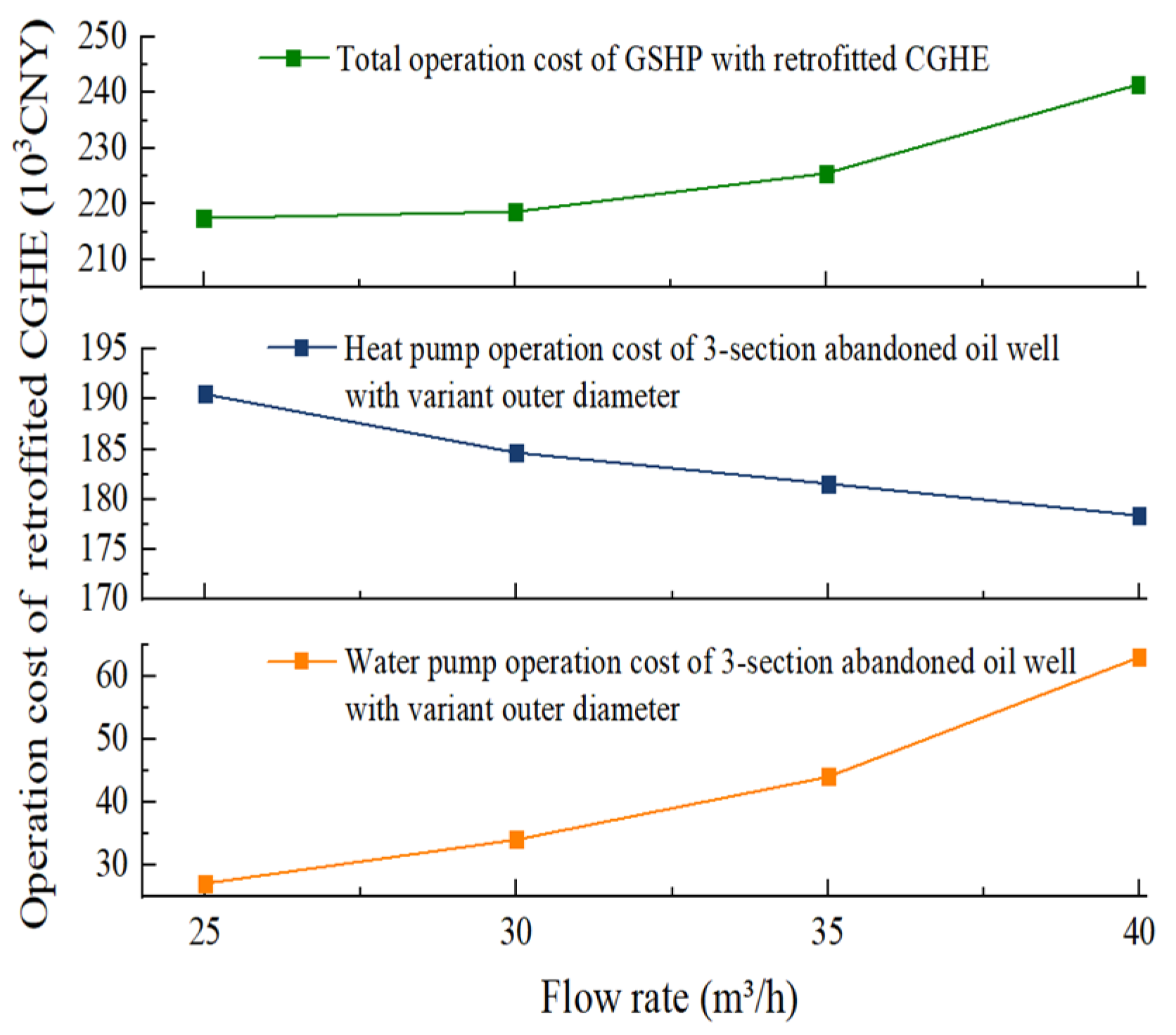
An economic analysis of the retrofit, considering the operation costs of the water pump and heat pump, was performed. Given the fact that the CGHE in this study was retrofitted from the abandoned oil wells, the drilling cost can be reduced by up to CNY 1800 thousand. The pump operation cost of CGHE retrofitted from three-section abandoned oil wells is significantly increase with the increase in the flow rate, while the heat pump operation cost decreases because the COP increases.
(3)
This study integrates actual project considerations to determine the most appropriate circulation flow based on building load requirements. From an economic perspective, a flow rate of 35 m³/h is selected as the optimal choice, which aligns with both the economic efficiency and operation stability of the middle and deep CGHEs.
In future research, the transformation project of the abandoned wells should be considered, and the interaction between the Wells should be deeply studied. Among them, the heat radius is the problem we must consider.

Author Contributions

Methodology, R.-J.L. and W.-S.Z.; writing—original draft, L.-R.J.; writing—review and editing, P.C., L.-R.J., M.-Z.Y. and X.-D.Z.; supervision, P.C. All authors have read and agreed to the published version of the manuscript.

Funding

This work was supported by the National Natural Science Foundation of China (52278115); the Natural Science Foundation of Shandong Province, China (ZR2020ME219); and the Leading Researcher Studio Fund of Jinan (Grant No.202333050).

Institutional Review Board Statement

The study did not require ethical approval.

Informed Consent Statement

The study did not involve humans.

Data Availability Statement

The study’s data is unavailable due to privacy.

Conflicts of Interest

The authors declare no conflict of interest.

Abbreviations

AOGWabandoned oil and gas wells
CGHEcoaxial geothermal heat exchanger
DBHEdeep borehole heat exchanger
EGSenhanced geothermal systems
FDMfinite difference method
FVMfinite volume method
GSHPground source heat pump

Nomenclature

athermal diffusivity (m2/s)
c, cf, cgspecific heat capacity of the circulating fluid (J/(kg·K))
C, C1, C2heat capacity of the circulating fluid (J/(m·K))
d, do, di, d1i, d1o, d2i, d2o pipe diameter (m)
Δ pffrictional pressure drops (Pa)
Δ pslocal pressure drops (Pa)
Hj bottom coordinate of the j-layer
k, kg, kp1, kp2thermal conductivity (W/(m·K))
qggeothermal heat flux (W/m2)
h1, h2, haconvective heat transfer coefficients (W/(m2·K))
K, K1, K2height of the equivalent coarse grain (m)
lpipe length (m)
Mcirculating fluid flow rate (kg/s)
Ppower consumption (W)
Qtotal heat transfer rate of the CGHE (W)
rradial coordinate (m)
rbborehole radius (m)
rbndthe radius of the radial boundary (m)
R1, R2thermal resistance ((m·k)/W)
taambient air temperature (°C)
uaverage section velocity (m/s)
vkinematic viscosity (m2/s)
ρ, ρf, ρgdensity (kg/m3)
λfriction factor

References

  1. Li, J.; Zhu, T.; Li, F.; Wang, D.; Bu, X.; Wang, L. Performance Characteristics of Geothermal Single Well for Building Heating. Energy Eng. 2021, 118, 517–534. [Google Scholar] [CrossRef]
  2. Rubio-Maya, C.; Ambríz Díaz, V.M.; Pastor Martínez, E.; Belman-Flores, J.M. Cascade Utilization of Low and Medium Enthalpy Geothermal Resources—A Review. Renew. Sustain. Energy Rev. 2015, 52, 689–716. [Google Scholar] [CrossRef]
  3. Davis, A.P.; Michaelides, E.E. Geothermal Power Production from Abandoned Oil Wells. Energy 2009, 34, 866–872. [Google Scholar] [CrossRef]
  4. Lund, J.W.; Toth, A.N. Direct Utilization of Geothermal Energy 2020 Worldwide Review. Geothermics 2021, 90, 101915. [Google Scholar] [CrossRef]
  5. Jia, L.; Lu, L.; Chen, J.; Han, J. A Novel Radiative Sky Cooling-Assisted Ground-Coupled Heat Exchanger System to Improve Thermal and Energy Efficiency for Buildings in Hot and Humid Regions. Appl. Energy 2022, 322, 119422. [Google Scholar] [CrossRef]
  6. Jia, L.; Lu, L.; Chen, J. Exploring the Cooling Potential Maps of a Radiative Sky Cooling Radiator-Assisted Ground Source Heat Pump System in China. Appl. Energy 2023, 349, 121678. [Google Scholar] [CrossRef]
  7. Chmielowska, A.; Tomaszewska, B.; Sowida, A. The Utilization of Abandoned Petroleum Wells in Geothermal Energy Sector. Worldwide Trends and Experience. In Proceedings of the E3S Web of Conferences, Krynica, Poland, 12–14 June 2020; Volume 154, p. 05004. [Google Scholar] [CrossRef]
  8. Morita, K.; Bollmeier, W.S.; Mizogami, H. Analysis of the Results from the Downhole Coaxial Heat Exchanger (DCHE) Experiment in Hawaii. Trans. Geotherm. Resour. Counc. 1992, 16, 17–23. [Google Scholar]
  9. Morita, K.; Bollmeier, W.S.; Mizogami, H. An Experiment to Prove the Concept of the Downhole Coaxial Heat Exchanger (DCHE) in Hawaii. Geothermal Res. Council Trans. 1992; 16, 9–16. [Google Scholar]
  10. Kohl, T.; Brenni, R.; Eugster, W. System Performance of a Deep Borehole Heat Exchanger. Geothermics 2002, 31, 687–708. [Google Scholar] [CrossRef]
  11. Kohl, T.; Salton, M.; Rybach, L. Data Analysis of the Deep Borehole Heat Exchanger Plant Weissbad (Switzerland). In Proceedings of the World Geothermal Congress, Kyushu-Tohoku, Japan, 28 May–10 June 2000. [Google Scholar]
  12. Nian, Y.-L.; Cheng, W.-L. Insights into Geothermal Utilization of Abandoned Oil and Gas Wells. Renew. Sustain. Energy Rev. 2018, 87, 44–60. [Google Scholar] [CrossRef]
  13. Cheng, W.-L.; Li, T.-T.; Nian, Y.-L.; Xie, K. Evaluation of Working Fluids for Geothermal Power Generation from Abandoned Oil Wells. Appl. Energy 2014, 118, 238–245. [Google Scholar] [CrossRef]
  14. Cheng, W.-L.; Liu, J.; Nian, Y.-L.; Wang, C.-L. Enhancing Geothermal Power Generation from Abandoned Oil Wells with Thermal Reservoirs. Energy 2016, 109, 537–545. [Google Scholar] [CrossRef]
  15. Cui, G.; Ren, S.; Zhang, L.; Ezekiel, J.; Enechukwu, C.; Wang, Y.; Zhang, R. Geothermal Exploitation from Hot Dry Rocks via Recycling Heat Transmission Fluid in a Horizontal Well. Energy 2017, 128, 366–377. [Google Scholar] [CrossRef]
  16. Caulk, R.A.; Tomac, I. Reuse of Abandoned Oil and Gas Wells for Geothermal Energy Production. Renew. Energy 2017, 112, 388–397. [Google Scholar] [CrossRef]
  17. Gharibi, S.; Mortezazadeh, E.; Hashemi Aghcheh Bodi, S.J.; Vatani, A. Feasibility Study of Geothermal Heat Extraction from Abandoned Oil Wells Using a U-Tube Heat Exchanger. Energy 2018, 153, 554–567. [Google Scholar] [CrossRef]
  18. Kujawa, T.; Nowak, W.; Stachel, A.A. Utilization of Existing Deep Geological Wells for Acquisitions of Geothermal Energy. Energy 2006, 31, 650–664. [Google Scholar] [CrossRef]
  19. Templeton, J.D.; Ghoreishi-Madiseh, S.A.; Hassani, F.; Al-Khawaja, M.J. Abandoned Petroleum Wells as Sustainable Sources of Geothermal Energy. Energy 2014, 70, 366–373. [Google Scholar] [CrossRef]
  20. Fang, L.; Diao, N.; Shao, Z.; Zhu, K.; Fang, Z. A Computationally Efficient Numerical Model for Heat Transfer Simulation of Deep Borehole Heat Exchangers. Energy Build. 2018, 167, 79–88. [Google Scholar] [CrossRef]
  21. Song, X.; Wang, G.; Shi, Y.; Li, R.; Xu, Z.; Zheng, R.; Wang, Y.; Li, J. Numerical Analysis of Heat Extraction Performance of a Deep Coaxial Borehole Heat Exchanger Geothermal System. Energy 2018, 164, 1298–1310. [Google Scholar] [CrossRef]
  22. Saadi, M.S.; Gomri, R. Investigation of Dynamic Heat Transfer Process through Coaxial Heat Exchangers in the Ground. Int. J. Hydrogen Energy 2017, 42, 18014–18027. [Google Scholar] [CrossRef]
  23. Yang, M.; Li, X.; Deng, J.; Meng, Y.; Li, G. Prediction of Wellbore and Formation Temperatures during Circulation and Shut-in Stages under Kick Conditions. Energy 2015, 91, 1018–1029. [Google Scholar] [CrossRef]
  24. Bu, X.; Ma, W.; Li, H. Geothermal Energy Production Utilizing Abandoned Oil and Gas Wells. Renew. Energy 2012, 41, 80–85. [Google Scholar] [CrossRef]
  25. Yekoladio, P.J.; Bello-Ochende, T.; Meyer, J.P. Design and Optimization of a Downhole Coaxial Heat Exchanger for an Enhanced Geothermal System (EGS). Renew. Energy 2013, 55, 128–137. [Google Scholar] [CrossRef]
  26. Beier, R.A.; Acuña, J.; Mogensen, P.; Palm, B. Transient Heat Transfer in a Coaxial Borehole Heat Exchanger. Geothermics 2014, 51, 470–482. [Google Scholar] [CrossRef]
  27. Nian, Y.-L.; Cheng, W.-L. Evaluation of Geothermal Heating from Abandoned Oil Wells. Energy 2018, 142, 592–607. [Google Scholar] [CrossRef]
  28. Bertani, R. Geothermal Power Generation in the World 2010–2014 Update Report. Geothermics 2016, 60, 31–43. [Google Scholar] [CrossRef]
  29. Winterton, R.H.S. Where did the Dittus and Boelter equation come from? Int. J. Heat Mass Transfer 1998, 41, 809–810. [Google Scholar] [CrossRef]
  30. Gnielinski, V. On Heat Transfer in Tubes. Int. J. Heat. Mass. Transf. 2013, 63, 134–140. [Google Scholar] [CrossRef]
  31. Jia, L.; Lu, L.; Cui, P.; Chen, J.; Pan, A. A Novel Study on Influence of Ground Surface Boundary Conditions on Thermal Performance of Vertical U-Shaped Ground Heat Exchanger. Sustain. Cities Soc. 2024, 100, 105022. [Google Scholar] [CrossRef]
  32. Rao, Z.; Li, M.; Li, M.; Liu, P.; Zhao, L.; Lv, Y. Deep casing-buried pipe heat exchanger heat-economic analysis and application. J. Cent. South Univ. (Nat. Sci. Ed.) 2022, 53, 4749–4761. [Google Scholar]
  33. Miansari, M.; Valipour, M.A.; Arasteh, H.; Toghraie, D. Energy and Exergy Analysis and Optimization of Helically Grooved Shell and Tube Heat Exchangers by Using Taguchi Experimental Design. J. Therm. Anal. Calorim. 2020, 139, 3151–3164. [Google Scholar] [CrossRef]
  34. Zhang, H.; Yu, Y.; Hu, C. Buried pipe diameter selection of ground source heat pump. HVAC Units 2012, 42, 114–117. [Google Scholar]
  35. Gan, X.; Pei, J.; Pavesi, G.; Yuan, S.; Wang, W. Application of Intelligent Methods in Energy Efficiency Enhancement of Pump System: A Review. Energy Rep. 2022, 8, 11592–11606. [Google Scholar] [CrossRef]
Figure 1. Schematic diagram of CGHE with varied outer pipe diameters. (The colors in the figure represent the water temperature, which is red when it is higher and blue when it is lower).
Sustainability 16 01603 g001
Figure 2. Numerical discretization of the CGHE. (The colors in the figure represent the water temperature, which is red when it is higher and blue when it is lower).
Sustainability 16 01603 g002
Figure 3. Flowchart to calculate the circulating fluid temperature of the CGHE with varying outer pipe diameters.
Sustainability 16 01603 g003
Figure 4. Comparison of simulated and measured outlet temperatures with the [32].
Sustainability 16 01603 g004
Figure 5. Analysis of average heat extraction of orthogonal test.
Sustainability 16 01603 g005
Figure 6. The space-heating load profile during the whole winter period.
Sustainability 16 01603 g006
Figure 7. Inlet temperature variation in the CGHE under different flow rates. (a) Long-term temperature profiles (0–2880 h). (b) Short-term temperature profiles (1200–1900 h).
Sustainability 16 01603 g007
Figure 8. Heat transfer coefficients and resistances of the CGHE under different flow rates. (a) Convective heat transfer coefficient. (b) Heat transfer resistances per unit length of CGHE.
Sustainability 16 01603 g008
Figure 9. Ground temperature after different operation periods: (a) 480 h and (b) 2880 h.
Sustainability 16 01603 g009
Figure 10. Total pressure drops of the CGHE under different flow rates.
Sustainability 16 01603 g010
Figure 11. Variation in heat pump COP with flow rates. (a) Linear fit curve of COP. (b) The COP variations in GSHP with different flow rates.
Sustainability 16 01603 g011
Figure 12. Variation in heat pump operation cost with flow rates.
Sustainability 16 01603 g012
Figure 13. Operation costs of GSHP with retrofitted 3-section abandoned oil well.
Sustainability 16 01603 g013
Table 1. Basic parameters of the four different sections.
No.Length of Borehole
(m)
Borehole Diameter
(m)
External Diameter of the Outer Pipe
(m)
Inner Diameter of the Outer Pipe
(m)
k of the Ground
W/(m·K)
Specific Heat Capacity
106J/(Nm3·K)
First section0~4550.440.340.322.81.10
Second section455~20170.310.240.232.81.93
Third section2017~26260.220.180.163.01.41
Forth section2626~28290.150.140.123.52.24
Table 2. Schemes of orthogonal test.
Operating ConditionModeling Parameter
A: Configuration of CGHE Retrofitted from Abandoned Oil WellsB: Inlet TemperatureC: Flow Rate D: Thermal Conductivity of Inner Pipe kp2
(°C)(m³/h)(W/(M·K))
14-section with variant do of 2829 m5250.17
24-section with variant do of 2829 m10300.25
34-section with variant do of 2829 m15350.34
44-section with variant do of 2829 m20400.43
53-section with variant do of 2626 m5300.34
63-section with variant do of 2626 m10250.43
73-section with variant do of 2626 m15400.17
83-section with variant do of 2626 m20350.25
94-section with constant do of 2829 m5350.43
104-section with constant do of 2829 m10400.34
114-section with constant do of 2829 m15250.25
124-section with constant do of 2829 m20300.17
133-section with constant do of 2626 m5400.25
143-section with constant do of 2626 m10350.17
153-section with constant do of 2626 m15300.43
163-section with constant do of 2626 m20250.34
Table 3. Results of orthogonal test.
Operating ConditionCombination of FactorsAverage Heat Extraction
(kW)
1A1B1C1D1422.18
2A1B2C2D2385.94
3A1B3C2D2344.84
4A1B3C3D3305.00
5A2B1C2D3383.09
6A2B2C1D4324.62
7A2B3C4D1319.11
8A2B4C3D2269.08
9A3B1C3D4420.76
10A3B2C4D3394.05
11A3B3C1D2326.41
12A3B4C2D1301.88
13A4B1C4D2393.67
14A4B2C3D1349.02
15A4B3C2D4292.01
16A4B4C1D3247.68
Table 4. Analysis of average heat extraction rate of orthogonal test.
Analysis of RangeABCD
n1364.5404.9330.2348.0
n2324.0363.4340.7343.8
n3360.8320.6345.9342.4
n4320.6280.9353.0335.6
Ri43.912422.712.5
Table 5. Technical performance parameter table of the heat pump unit.
Performance ParameterNumber
Nominal heating capacity500 kW
Designed inlet and outlet water temperatures of the evaporator15/7 °C
Design inlet and outlet water temperatures of the condenser40/45 °C
Nominal power consumption115 kW
Rated COP4.48
Table 6. Calculation parameters of the convection heat transfer coefficient (25 m³/h).
Pipe TypeHydraulic Diameter
(m)
RePrNuh
(W/m2·K)
Annular pipe section 10.3216,287.799.02112.02315.78
Annular pipe section 20.2320,760.259.02136.02705.69
Annular pipe section 30.1625,844.409.02162.072113.49
Inner pipe0.0983,431.809.02413.882819.27
Table 7. Mathematical relation of convection heat transfer coefficients and flow rates.
Pipe TypeFitted Curve
Annular pipe section 1y = 79.86 ± 15 + (9.43 ± 0.4) × xy: convection heat transfer coefficient (W/m2·K)
x: flow rate (m3/h)
Annular pipe section 2y = 178.53 ± 34 + (21.07 ± 1.0) × x
Annular pipe section 3y = 548.87 ± 162 + (62.40 ± 4.9) × x
Inner pipey = 712.90 ± 135 + (84.19 ± 4.0) × x
Table 8. Drilling cost of CGHE with different borehole depths.
Buried Depth1000 m1500 m2000 m2500 m3000 m
Drilling cost (103CNY)600900120015001800
Table 9. Cost of pipe material of CGHE with different borehole depths.
Buried Depth1000 m1500 m2000 m2500 m3000 m
Pipe material cost (103CNY)44066088011001320
Table 10. Mathematical relation of total pressure drops and flow rates.
Pipe TypeFitted Curve
Annular pipe section 1y = −8.07 ± 0.82 + (0.51 ± 0.02) × xy: total pressure drop (m)
x: flow rate (m3/h)
Annular pipe section 2y = −27.69 ± 2.82 + (1.75 ± 0.09) × x
Annular pipe section 3y = −10.80 ± 1.10 + (0.68 ± 03) × x
Inner pipey = 4.72
Disclaimer/Publisher’s Note: The statements, opinions and data contained in all publications are solely those of the individual author(s) and contributor(s) and not of MDPI and/or the editor(s). MDPI and/or the editor(s) disclaim responsibility for any injury to people or property resulting from any ideas, methods, instructions or products referred to in the content.

