Article

Evaluation of Powder- and Extrusion-Based Metal Additive Manufacturing Processes for the Sustainable Fabrication of Spare Parts in Electromobility

1
Fraunhofer Institute for Manufacturing Engineering and Automation IPA, 95447 Bayreuth, Germany
2
Chair Manufacturing and Remanufacturing Technology, University of Bayreuth, 95447 Bayreuth, Germany
3
Engineering Design and CAD, University of Bayreuth, 95447 Bayreuth, Germany
*
Author to whom correspondence should be addressed.
Sustainability 2024, 16(8), 3425; https://doi.org/10.3390/su16083425
Submission received: 19 March 2024 / Revised: 8 April 2024 / Accepted: 16 April 2024 / Published: 19 April 2024

Abstract

:
Electromobility promises to efficiently mitigate consequences of increasing traffic volume and its accompanied greenhouse gas emissions. On an individual level, electrified bikes allow emission free electrified mobility at moderate costs, and consequently their stock has increased significantly in recent years. This simultaneously increases the demand for spare parts, which are often manufacturer- or application-specific, and due to many variants, challenging to provide for the market. This article evaluates powder-based and extrusion-based metal additive manufacturing of a typical electrified bike component. The overarching objective is to establish a sustainable spare parts supply in the field of electromobility by manufacturing spare parts in a resource-efficient and decentralized manner. This approach aims to eliminate the need for physical storage space and long transport routes for the provision of spare parts, while significantly increasing the service life of e-bikes. The investigation demonstrates how these parts can be additively manufactured function equivalent and with sufficient mechanical properties, also taking economical aspects into account. Furthermore, the needed resources and related environmental consequences for metal-based additive manufacturing spare-part production are compared for both process routes. The results show that both routes are capable of producing spare-parts at comparatively the same mechanical performance, with the mechanical performance of the initial part clearly surpassed. Furthermore, it can be observed that both routes exhibit comparable resource costs, with the powder bed fusion of metals using laser beams showing significantly lower energy and gas costs by more than ten times, but higher material costs that are approximately twice as high as those of atomic diffusion additive manufacturing. Therefore, additive manufacturing offers a promising opportunity to rapidly produce parts in small quantities which are resource efficient.

1. Introduction

Electromobility is a promising approach for dealing with the increasing volume of traffic worldwide and for limiting global emissions of climate-damaging emissions [1]. The sales figures and the stock of electrified bikes (e-bikes) have been rising continuously for years. At the end of 2022, the stock of e-bikes in Germany was close to 10 million units [2].
The lifetime of an e-bike is on average about 5 to 10 years [3,4]. Due to the high number of e-bikes, the number of defects is also increasing. A defect of an e-bike can be traced back to mechanical components of the classic bicycle on the one hand. These components are mostly standardized, and spare parts are widely available [5]. On the other hand, a defect can be attributed to the additional components of the assemblies built into an e-bike, which distinguish the e-bike from the classic bicycle [5]. The components contained in these assemblies are often manufacturer- and application-specific and, due to the high number of variants, spare parts are more difficult to provide [6].
In a survey of 45 bicycle repair shops, the majority of defects in e-bikes were attributed to defects in mechanical components of the assemblies specific to an e-bike (e.g., components of an electric motor) [6]. Furthermore, the bicycle repair shops surveyed stated that instead of replacing the defect individual components, the entire assembly is replaced in almost 65% of cases because the components are not available as spare parts even in the early years after the market launch of e-bikes [6]. However, the availability of spare parts is crucial for the sustainable implementation of electric mobility. One approach to solve this problem is the decentralized production of e-bike specific spare parts by bicycle repair shops.
Due to global networking, the complexity of supply chains of goods and services is increasing [7]. The COVID-19 outbreak illustrates that even single failures along a supply chain can lead to its entire disruption [8]. Additive manufacturing (AM) has great potential to respond quickly to failures along the supply chain [8]. By eliminating the need for specific machining tools, AM has great potential to economically produce the required spare parts in small quantities [9,10]. This means that extensive transport routes and costly warehousing can be avoided [11]. Additionally, by eliminating the manufacturing constraints of conventional production processes typically used for e-bike components, AM enables components to be even better adapted to the specific application. These include, for example, a reduction in component mass through a topology-optimized or bionic component design [12]. Furthermore, by exploiting the manufacturing freedom of AM processes, additional functions can be integrated or the components can be better adapted to customer requirements [13]. Various additive manufacturing processes exist for the production of metallic components (see Figure 1). Due to their prevalence, the metal-based additive manufacturing processes of powder bed fusion, material extrusion, material/binder jetting, and direct energy deposition are generally suitable for spare part fabrication. However, material/binder jetting and direct energy deposition exhibit relatively high machine costs, even for small build volumes, or high surface roughness of the manufactured components, necessitating subsequent machining. As a result, their potential for spare part fabrication in bicycle repair shops is considered lower compared to powder bed fusion and material extrusion. While mechanical performance and improvements of part tolerances and process robustness were a strong focus in recent research, comparative studies, especially linked with aspects of sustainability or economic factors, are scarce.
One prerequisite for the use of additively manufactured spare parts is their quality, in particular their mechanical load capacity [15]. A wide range of AM processes exists, which are in principle suitable for decentralized spare parts production at bicycle repair shops. Many studies have already demonstrated the advantages and disadvantages of AM on classical supply chains based on diverse applications from aerospace, medical, automotive, and consumer goods production [16,17,18,19,20,21,22]. The AM principle, in which material is only applied where it is needed, allows the manufacturing restrictions of conventional manufacturing processes to be circumvented and the component geometry to be adapted to the specific application. As a result, the mass of waste generated along the additive process chain can be reduced [11]. In a study by Blösch-Paidosh and Shea, it was shown that by considering the design freedoms of AM, promising new designs of e-bikes are made possible [23]. However, in addition to the possibility of integrating additional functions into the spare parts to be manufactured or reducing their mass, the required resource input for AM processes is crucial for an economically and ecologically spare part production [24,25,26]. There are a large number of studies on this, which attribute the success of AM compared to conventional manufacturing very heavily to the respective application and the additive manufacturing process. For example, Ingarao et al. have shown that especially the typically high energy demands for metal-based AM often lead to higher emissions compared to conventional manufacturing [27]. In contrast, by using the AM process of material extrusion, Top et al. were able to reduce the material requirements for manufacturing an industrial-scale product by over 60% and the emissions resulting from manufacturing by over 85% compared to conventional manufacturing [28]. By using AM, the production of the individual components itself proves to be more time-consuming, but by eliminating the need for specific molds or machining tools, the lead time could be shortened [28]. Schuhmann et al. showed that especially the cost calculation of AM of spare parts still has potential for improvement [26]. Although there are many cost models which often only consider the process and hardly the entire process chain [29], in contrast, Baumers et al. point out that due to the typically small number of process steps until the completion of the finished product, AM allows a more transparent calculation of material requirements and emissions compared to conventional manufacturing processes [30].
Furthermore, the implementation of AM-processes into the product development process allows a circular economy approach, as it removes valuable materials from waste streams by prioritizing product reuse, or repair [31]. Nevertheless, currently policies rather than evidence related to manufacturing process or material data are the main driver for eco-innovations [32]. Hence, this pushes companies and product developers towards eco-design, that often do not have the necessary toolkit nor knowledge to integrate strategies for reuse or repair into their product development process [13]. According to Hallstedt, this is in particular critical, since a product’s social-ecological impacts throughout its life cycle are largely defined in its early steps within the design process [33].
To provide product developers a guidance of metal-based AM’s capabilities for reuse and repair purposes, this article shows, by example of a typical component from an E-bike, how these parts can be additively manufactured by different metal-based AM processes with sufficient strength at which cost. Furthermore, this article elucidates the resources needed and resulting environmental consequences for metal-based AM spare-part production. It is the objective of this article to investigate alternative routes for achieving a sustainable spare part supply, thus the original part is not replicated rather than manufactured function equivalent by the AM processes. Therefore, this research contributes to sustainability by enabling a decentralized supply chain of spare parts and eliminating the need for long-distance transportation. Furthermore, the digital archiving of parts eliminates the need for storage space in logistics centers or warehouses. The implementation of AM for resource-efficient and cost-effective spare part supply in bicycle repair shops can significantly extend the lifespan of e-bikes.

2. Materials and Methods

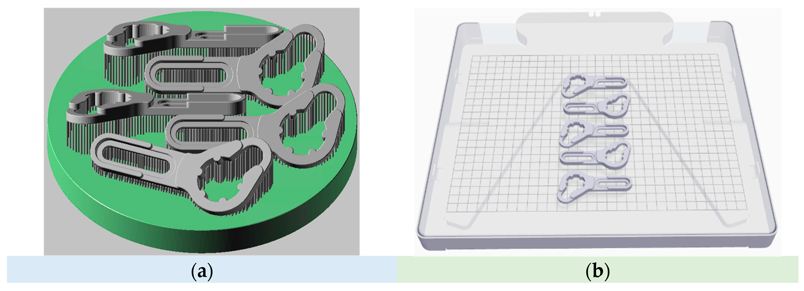
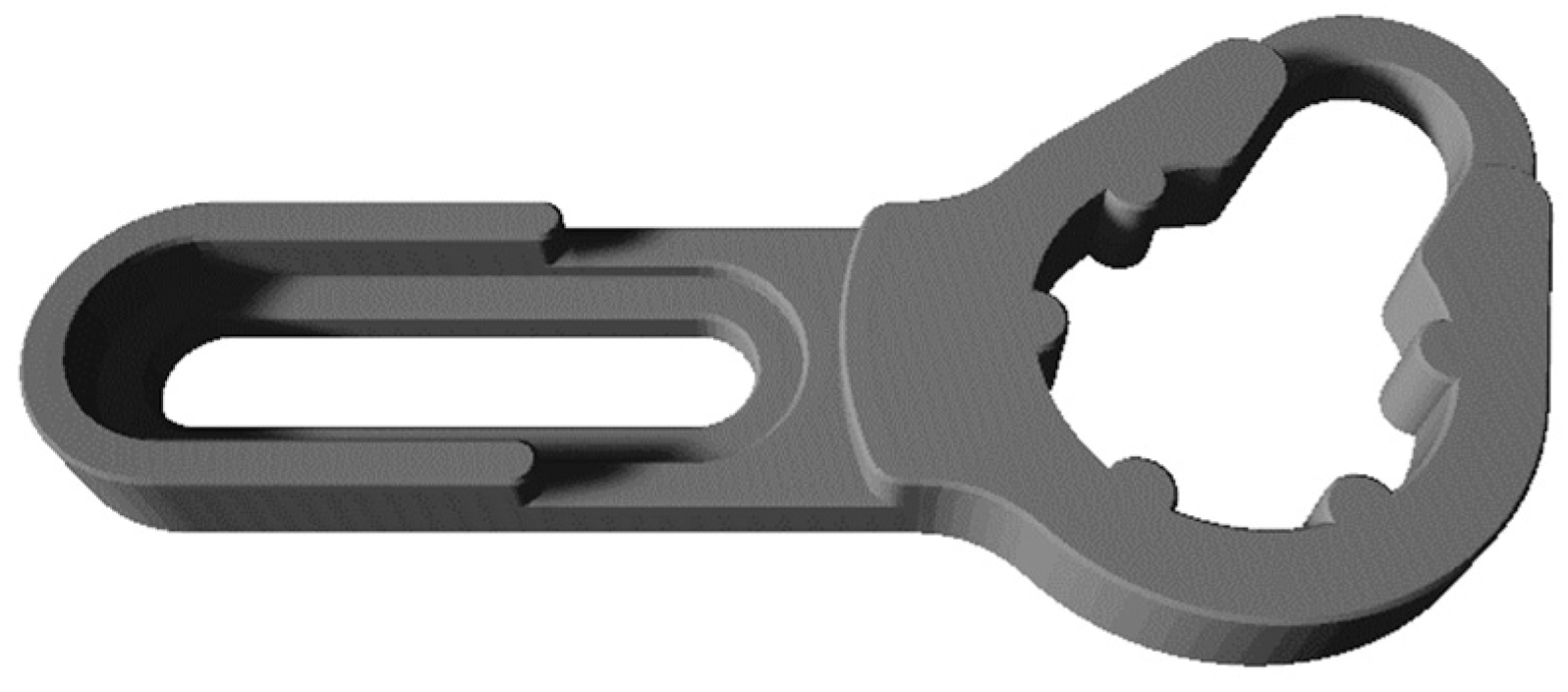
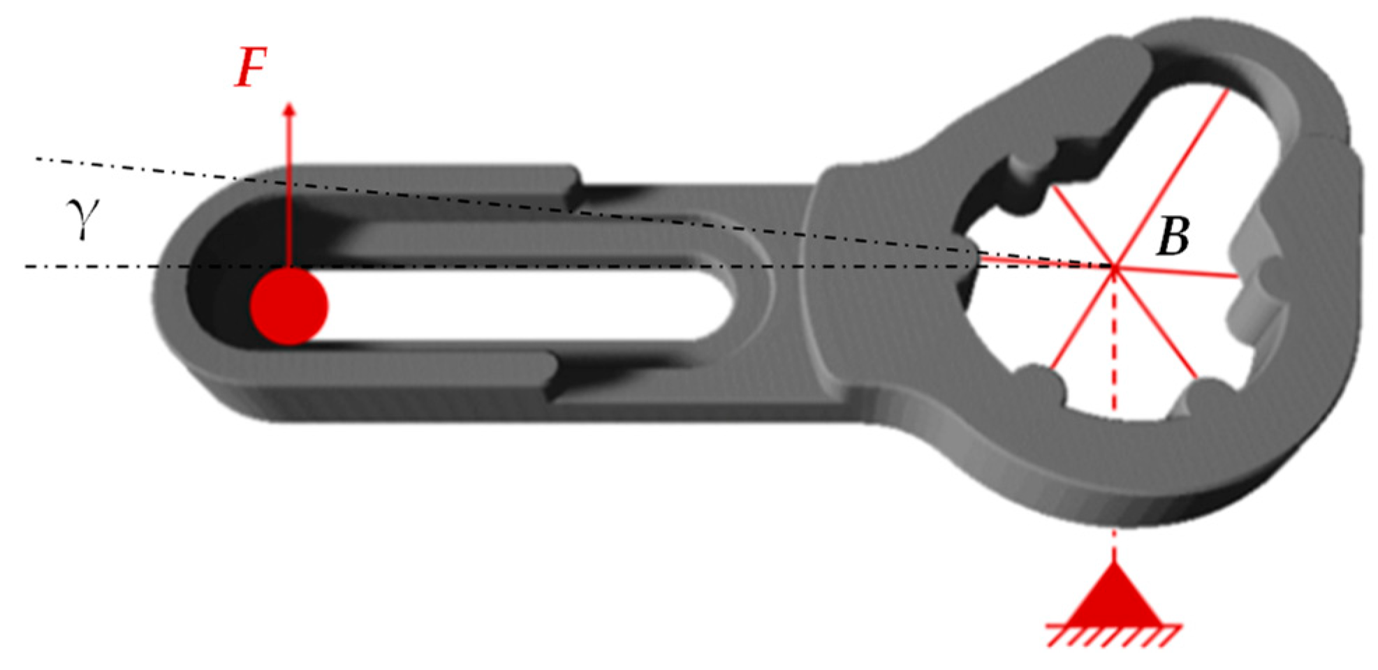
2.1. Use Case Torque Arm

The aviation industry typically faces stringent requirements for spare part supply due to the high costs associated with downtimes. At the same time, it is hardly possible for an airline to stock all components of an aircraft in sufficient numbers as spare parts [11]. This is due to the fact that several million different components are often installed in an aircraft [34]. In comparison, the number of components installed in e-bikes is significantly lower. Therefore, e-bikes have more variants, and there also exists more bicycle repair shops that must keep the potentially necessary spare parts on hand to be able to react flexibly to the defects of individual components and thus minimize the downtimes of e-bikes.
The torque arm represents a component of an e-bike with a particularly high number of variants, and at the same time with a high probability of failure [5]. In addition, the torque arm is typically required to retrofit an electric motor to classic bicycles. The torque arm is a metallic component that is typically located on the motor shaft, absorbs the differential torque of the drive and output, and introduces it into the frame of the e-bike.
A prerequisite for the use of AM is the availability of a three-dimensional data model of the component to be manufactured. However, bicycle repair shops typically do not have the three-dimensional data models of the components to be manufactured [5]. A good part of the three-dimensional data models can be generated by decentralized measuring and then designing it using a CAD program. Alternatively, a digital three-dimensional data model can be generated from a good part by means of a decentralized tactile or imaging measurement process, e.g., 3D scanning.
The torque arm used in this study (see Figure 2) was developed by Electric Bike Solutions GmbH (Heidelberg, Germany) for retrofitting a special front hub motor, the so called moak08, to a classic bicycle. A similar torque arm with the same function is currently not available on the market. When using the upgraded e-bike, the torque arm must transmit a motor torque of 10 Nm, which can increase up to 25 Nm under high load.

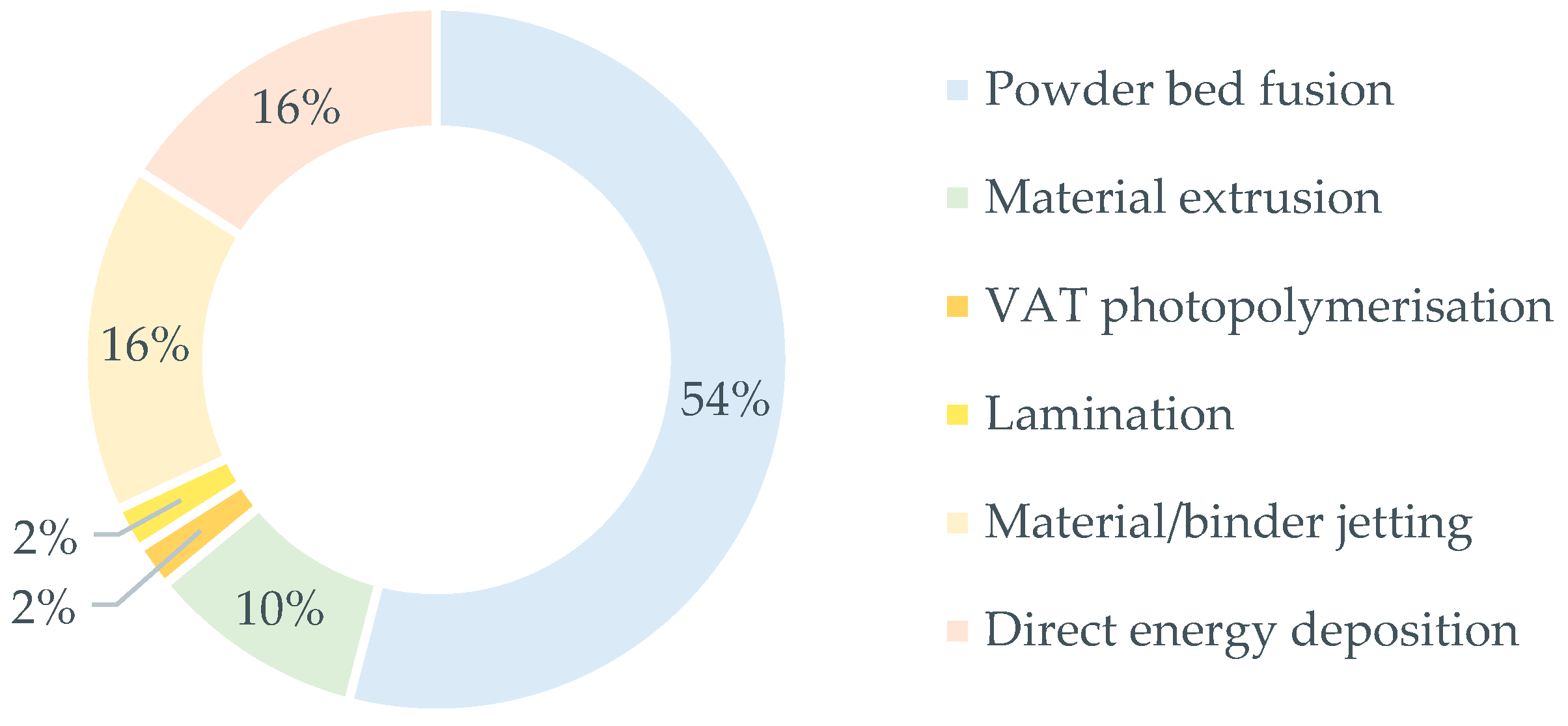
2.2. AM Processes Used

Within the scope of the present work, five torque arms were manufactured using the two metal-based AM processes Powder Bed Fusion of Metals via Laser Beam (PBF-LB/M) and Atomic Diffusion Additive Manufacturing (ADAM). For a comparison of both AM processes, their entire process chain must be analyzed in detail. Thus, in the following sections, the AM processes, and the corresponding process steps for the entire process chain, including component preparation and post-processing, are described along the PRE-, IN-, and POST-process phases. In both cases, common machine parameter and materials were used to manufacture function equivalent spare parts for the moak08.

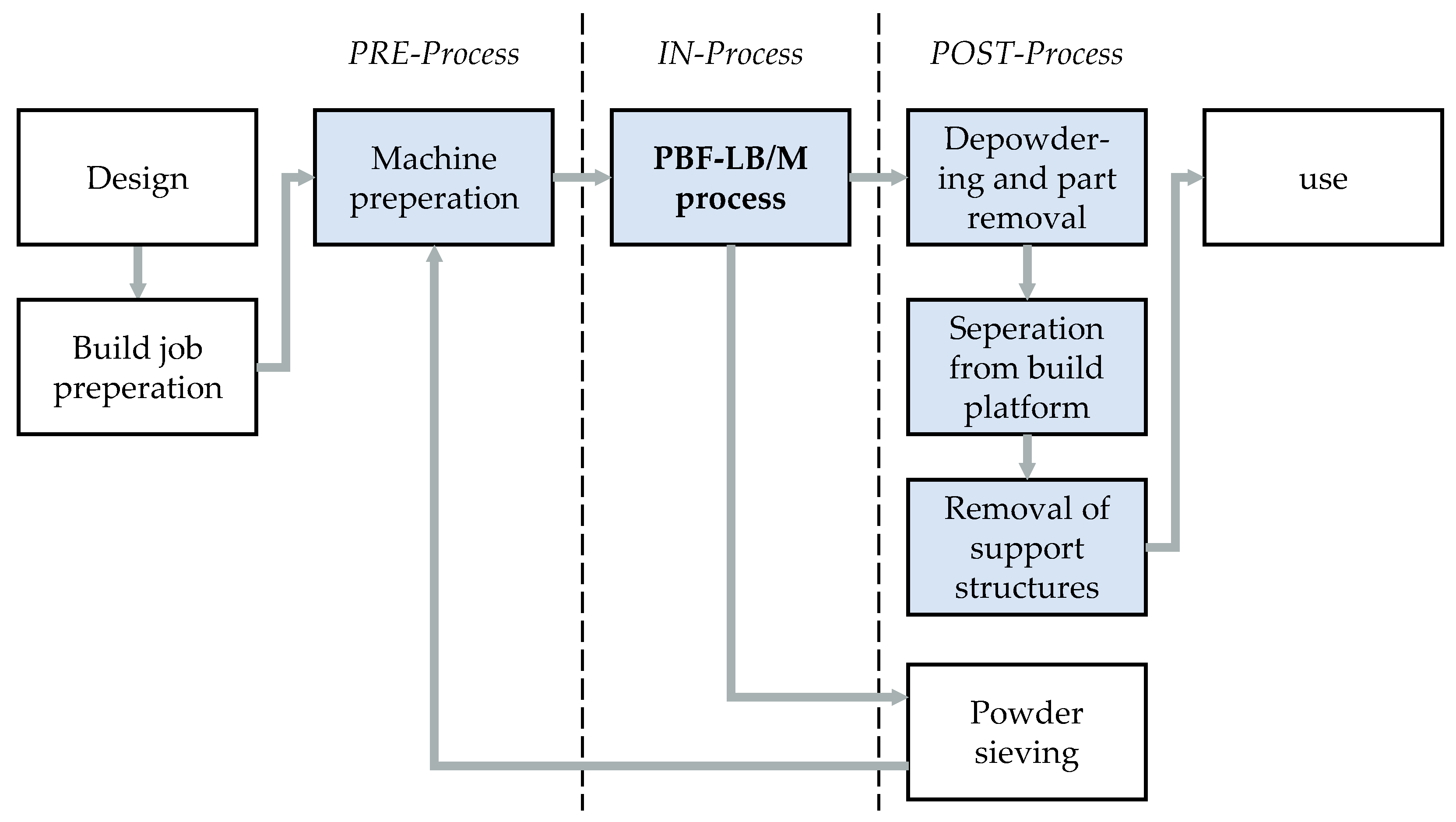
2.2.1. Powder Bed Fusion of Metals via Laser Beam

Powder Bed Fusion of Metals via Laser Beam (PBF-LB/M) is the most widely used AM process for metallic components [35]. The AM process is based on a cyclic process sequence in which the required components are built up layer by layer.
The cyclic process sequence consists of a local application of metal powder by means of a coater on a build platform or the already exposed powder layers, a selective exposure of the metal powder by means of a fiber laser and an incremental lowering of the build platform by one layer thickness. The entire PBF-LB/M process is carried out in an inert gas atmosphere. Process spatter and fume generated during the PBF-LB/M process are removed from the process chamber by an inert gas flow and separated in a process gas filter. In order to prevent distortion due to thermal stress in particular, the PBF-LB/M components are connected to the build platform via support structures [36]. The process steps of the PBF-LB/M process chain are assigned to the PRE- IN- and POST-Process phases in Figure 3.
The PBF-LB/M process is preceded by part design, data preparation of the build job, and preparation of the PBF-LB/M machine. After the PBF-LB/M process, loose metal powder is widely removed from the components by means of brushes. Subsequently, the components connected to the build platform via support structures are sucked off with a wet separator and removed from the construction chamber. After that, the components were cleaned by compressed air in a blasting cabin to completely remove the loose metal powder located between the support structures. Due to the low complexity of the geometry, the optional heat treatment step to reduce thermally induced residual stresses is not necessary to produce the torque arms, and is therefore not considered. After the de-powdering process, the torque arms are firstly removed from the build platform with pliers, and secondly the support structures are removed from the torque arms by hammer and chisel. After the surface of the torque arms has been smoothened by sandblasting, they are ready for use. At the end of the process chain, the metal powder, which was not melted in the PBF-LB/M process will be sieved to reuse it again.

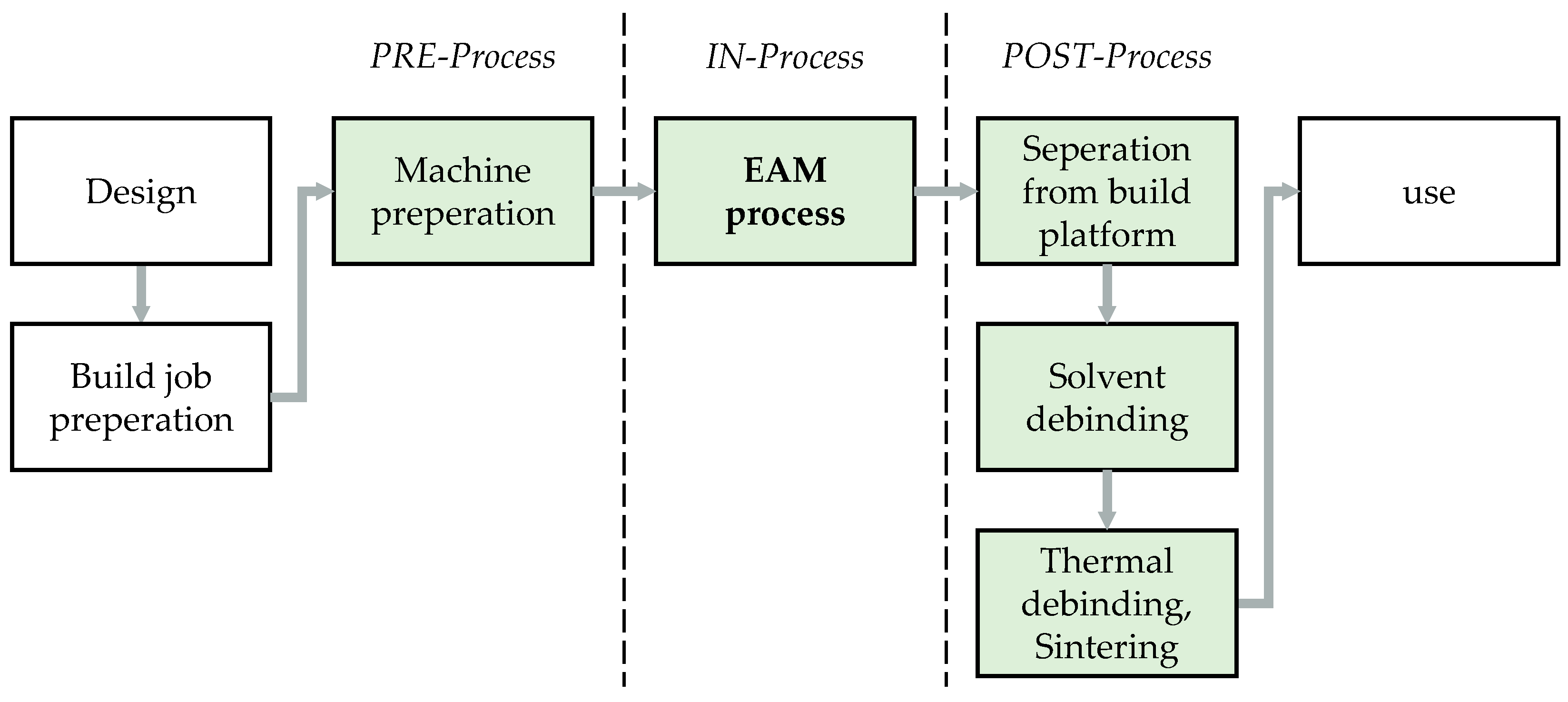
2.2.2. Metal Extrusion-Based Additive Manufacturing via Atomic Diffusion Additive Manufacturing

Atomic Diffusion Additive Manufacturing (ADAM) is an extrusion-based additive manufacturing (EAM) process by Markforged (Markforged Inc., Boston, MA, USA), which uses highly filled polymer filaments to fabricate metal parts by subsequent debinding and sintering (metal extrusion-based additive manufacturing, MEAM). The associated process steps of the MEAM process chain are assigned to the process phases PRE-, IN-, and POST-process, as shown in Figure 4.
After inserting the printing paper and clamping the filaments, the MEAM process takes place to manufacture the components. These components with any necessary support structures are subsequently manually removed from the build platform. Afterwards, the main-part of the organic binding-agent is removed in the debinding step, leaving behind a highly porous so-called brown part. In the final sintering process, rearrangement and diffusion effects are causing a densification of the part. The remaining backbone of the binding-agent is removed thermally, after the first so-called sinter necks have been formed. During sintering, the part is consolidated due to various diffusion processes, which leads to nearly full-dense parts [40,41]. While the equipment and periphery needed for powder bed-based metal AM processes is costly, MEAM promises a low-cost entry into metal AM [42]. Additionally, the EAM process allows to additively manufacture parts without any support structures if an overhang angle greater than 40° is in the design. Within this study, all specimens were fabricated using the Markforged D2 filament (Markforged Inc., Boston, MA, USA).

2.2.3. Comparison of Process Parameter

As part of the build job preparation, the torque arms were virtually positioned in the build chambers of the machines used for the PBF-LB/M and EAM process. Figure 5 shows the position and orientation of the torque arms on the build platform. The used process parameters for the PBF-LB/M and EAM process to manufacture the torque arms are listed in Table 1. In the following Table 2, the individual process steps of the two process chains are shown with the main resources used in each case. The process steps were assigned to the PRE, IN, and POST process phases.

2.3. Measurement of Resource Consumption and Process Time

The resource consumption along the process steps of the two process chains are recorded using various measuring devices; see Table 3. The metal powder or metal filament required to manufacture the torque arms is determined gravimetrically. The demand for different gases, such as argon or compressed air, is also measured using a thermal mass flow meter. The energy demand for the PBF-LB/M and EAM process, as well as for selected process steps with high energy demand, is recorded by means of a network analyzer. This is also used, just like a stopwatch, to record the time required for the process steps. Furthermore, the proportionate time and energy demand per process step was calculated by comparing it to the time and energy demand for completing the five torque arms.
It is to note here, that the proportional utilization rate of the gas filter is calculated based on the process time and the empirical value until the filter is replaced at regular intervals.

2.4. Testing of the Manufactured Torque Arms

For testing the torque arms, they were each fixed to the axis of rotation (cf. point B, Figure 6) and loaded with the force F applied to the slotted hole. To generate the maximum possible load on the torque arm in the test rig, the load was applied at the outer end of the slotted hole for each test sequence (maximum lever arm). During loading, the deformation of the torque arm was detected via the angular displacement γ. In this setup, the torque arms should withstand at least 20 Nm, whereby failure is indicated either by cracking or a dislocation angle of 30°. For each process chain, five torque arms were tested. In addition, original torque arms were tested and compared to the manufactured ones using PBF-LB/M and ADAM. The force was applied hydraulically with a constant testing velocity of 1° per second.

3. Results

3.1. Resource Requirements
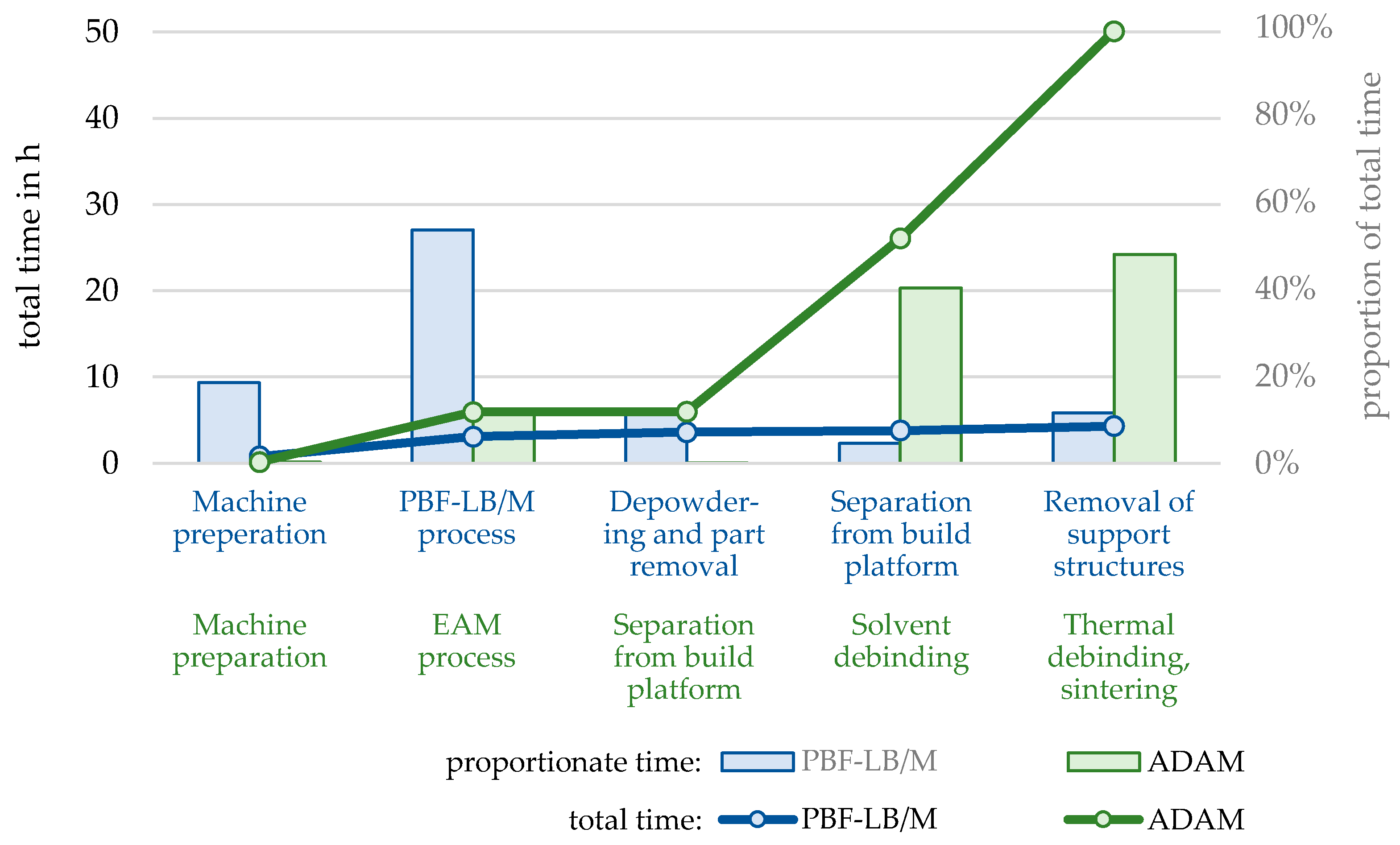
3.1.1. Lead Time

The lead time required to obtain five finished torque arms over the individual process steps is shown in Figure 7 for the PBF-LB/M and ADAM process chain. The lead time until completion of the five torque arms in the entire PBF-LB/M process chain is 4 h and 19 min, with the actual PBF-LB/M process accounting for 54% of the total time. The remaining process steps in the PRE and POST process phases range from 6 to 48 min. In contrast, the lead time until completion of the five torque arms in the ADAM process chain is 50 h and 25 min, which is nearly 12 times longer compared to the PBF-LB/M process chain. This increased time requirement is mainly due to the process steps of solvent debinding (20.1 h) and thermal debinding, sintering (24 h), which together account for about 88% of the total time until completion of the torque arms. The EAM process itself takes about 5 h and 48 min, which is approximately 150% longer compared to the PBF-LB/M process.

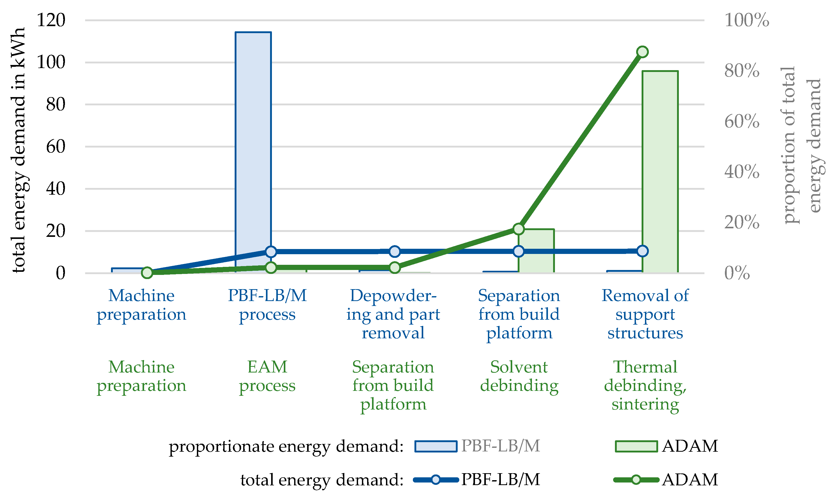
3.1.2. Energy Demand

Figure 8 shows the energy consumed for the process chain of PBF-LB/M and ADAM. When manufacturing the torque arms using the PBF-LB/M process chain, 95% of the energy demand, amounting to 10.2 kWh, is attributed to the PBF-LB/M process itself.
For the manufacturing of the torque arms using the EAM process, only 28% of the energy demand compared to the PBF-LB/M process is needed. However, the energy demand of the ADAM process chain (56.1 kWh) exceeds that of the PBF-LB/M process chain (10.5 kWh) by more than five times. This is due to the energy-intensive process steps of solvent debinding (18.3 kWh) and thermal debinding, sintering (35 kWh).

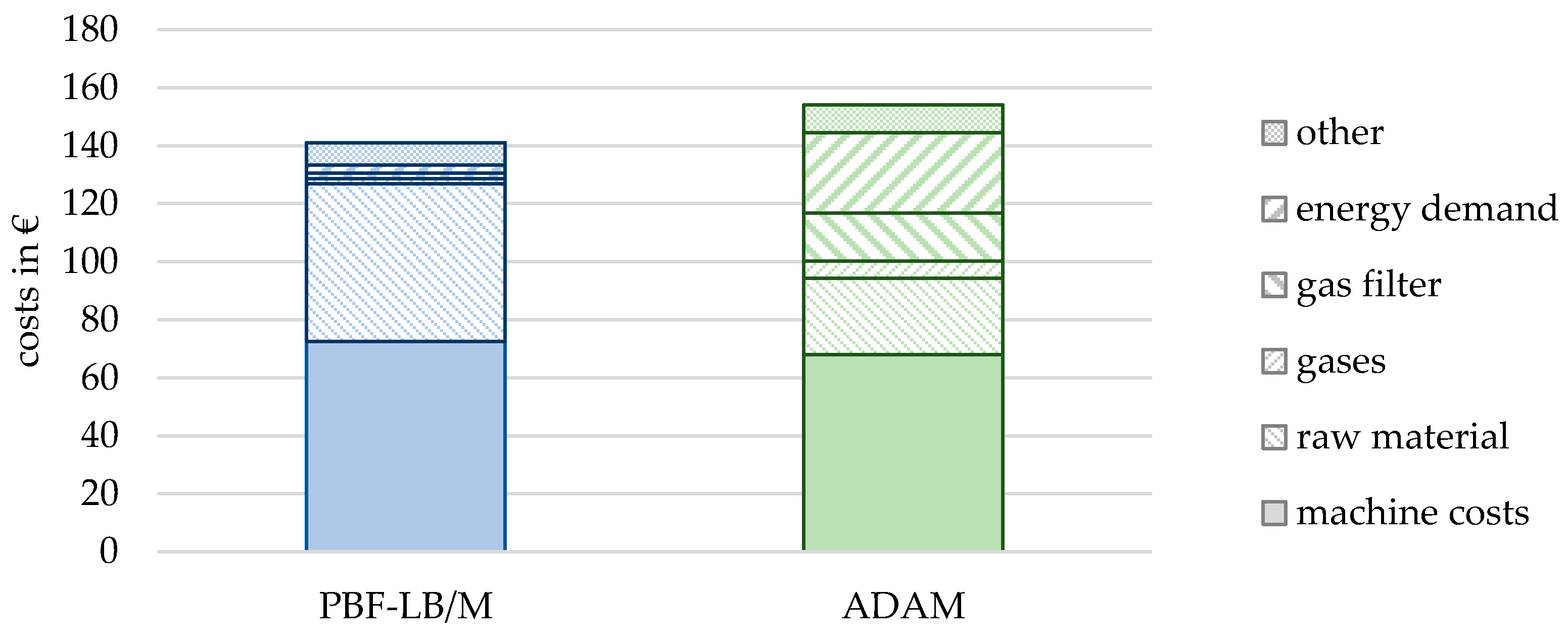
3.1.3. Cost of Resource Consumption

The quantity and the costs of the main resources used to manufacture the torque arms are listed in Table 4 for the PBF-LB/M process chain and in Table 5 for the ADAM process chain. The conversion of the quantity of resources into costs was based on the purchase prices of the respective resources. Furthermore, the costs of the AM machines are listed in both tables, which result from their runtime and the respective machine hourly rate. As the AM machines are responsible for around 80% of the total investment costs in both process chains, the costs of the remaining machines and peripherals are taken into account via the machine hourly rate of the AM machines.
It should be noted, here, that in the PBF-LB/M process chain, in addition to the direct losses of metal powder (e.g., as support structures or as metal powder in the process gas filter), further losses can occur in the downstream sieving process of the metal powder present in the PBF-LB/M machine, which were not considered in this study.
In the PBF-LB/M process chain, the costs of the PBF-LB/M machine account for the highest proportion, representing 51.5% of the total costs. Material costs are primarily driven by the expense of metal powder, which constitutes 79% (54.24 EUR) of the total. However, only 41.2% of the metal powder used actually ends up in the final components. The majority of the metal powder is lost during handling and in the form of support structures, spatter, and agglomerates during the PBF-LB/M process. These losses significantly contribute to the overall costs.
The cost of manufacturing the five torque arms in the ADAM process chain is 141.12 EUR slightly higher than in the PBF-LB/M process chain. At 48.3%, the machine costs are proportionately similar to the PBF-LB/M. The material costs are mainly attributed to the required metal filament (35.7%), debinding fluid (13.1%), the proportional use of the gas purification filter (19.2%), and the energy consumption (20.4%).

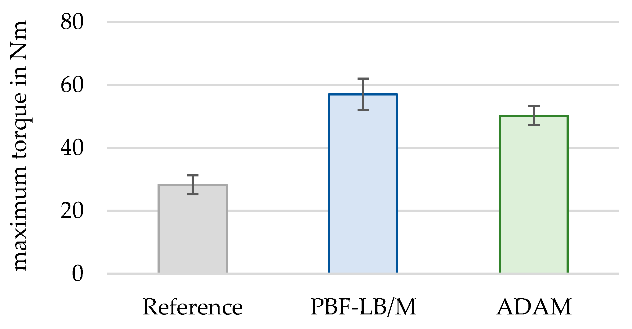
3.2. Testing of the Torque Arms

The resulting maximum torque for each tested configuration is plotted in Figure 9 with its standard deviation. The plot shows that the deviations between the measurements are small in all cases, while it is slightly higher for PBF-LB/M.
Based on the results in Figure 9, both AM-techniques show significantly higher values, which is attributed to the material change from aluminum, for the reference torque arm manufactured by milling, to titanium for the PBF-LB/M configuration and steel for the EAM configuration, respectively. As the objective was to use the standard process parameter for both AM-techniques, the PBF-LB/M configurations were printed solid, while for the ADAM parts a sparse triangular infill with approximately 37% relative density was used. Thus, it is reasonable that the PBF-LB/M titanium torque arm slightly predominates the ADAM steel configuration.

4. Discussion

Defects in e-bikes can be attributed to a large number of components, which is why additive manufacturing offers a promising opportunity to manufacture the required spare parts economically and quickly in small quantities. In this study, the additive manufacturing of five identical torque arms was examined as an application. A realistic load test demonstrated the required strength of the additively manufactured spare parts. By using different materials compared to the original component, an increase in strength of at least 218% was achieved.
The lead time for the torque arms depends heavily on the additive manufacturing process selected. With the PBF-LB/M process chain, the time required to manufacture five torque arms was 4.3 h, while with ADAM it took 50.4 h (see Figure 10). Single-part production of the torque arms would reduce the production time. In the PBF-LB/M process chain, the production time is mainly due to the layer-by-layer application of the metal powder and the exposure of the component cross section. Individual part production significantly shortens the exposure time due to the reduced component volume. This also applies to the EAM process. However, the EAM process only accounts for around 12% of the entire ADAM process chain, which means that the lead time for the torque arms is hardly affected. Most of the time in the ADAM process chain is accounted for the downstream process steps solvent debinding and thermal debinding, sintering. These process steps depend heavily on the number of components to be manufactured. At full capacity, 13 torque arms could be debindered and sintered simultaneously, and thus this has a significant effect on the runtime per part, but not the lead time until the first part is finished.
The energy consumption to produce the torque arms heavily depends on the selected AM process. In the PBF-LB/M process chain, the PBF-LB/M process itself accounts for 95% of the energy consumption. Reducing the number of components to be manufactured results in lower energy consumption, as the exposure time and production time would be reduced. In the ADAM process chain, the total energy consumption is about ten times higher than in the PBF-LB/M process chain (see Figure 11). In total, 97% of the energy consumption in the ADAM process chain is accounted for the process steps solvent debinding and thermal debinding, sintering. The process is economically viable when both the debinding station and sinter furnace are fully utilized, as the energy required for solvent debinding and thermal debinding, sintering, is independent of the number of components. Hence, single-part production would have hardly any effect on the absolute energy consumption. In contrast, batch production would reduce energy consumption per component significantly.
The costs for the additive manufacturing of five torque arms are similar for both processes, but slightly higher for the ADAM process chain. The material costs for both additive manufacturing processes are attributable to different cost factors (see Figure 12). In the PBF-LBM process chain, almost 80% of the material costs are attributable to the consumption of the raw material. In the ADAM process chain, this cost share is around 35%.
A major advantage over conventional manufacturing is that the complexity of a component has little influence on the additive manufacturing process. However, as the complexity increases, the material usage can also increase due to the need for support structures. In the ADAM process chain, this would require the use of ceramic release filaments. The fabrication of support structures would consequently increase the process time and energy demand in both manufacturing routes. Nevertheless, by appropriately orienting the component within the build chamber, the need for support structures can be reduced to some extent, even for complex component geometries.
The PBF-LB/M process chain offers advantages in terms of early component availability. The ADAM process chain has advantages for larger quantities, as the post-processing systems of the downstream process steps were only slightly utilized in this application. The machines required to manufacture the torque arms are expensive for both process chains, which is why internal production in bicycle repair shops only makes economic sense when capacity utilization is high. In addition, the implementation of additive manufacturing processes in bicycle repair shops requires overcoming further challenges. In the case of powder bed fusion, particular attention needs to be given to occupational safety due to the hazards associated with metal powders [43]. As for material extrusion, the influence of debinding and sintering on part quality is still relatively unexplored [14]. Overall, further research is needed to fulfill the “First Time Right” approach, which is essential for the economic viability of additive manufacturing in bicycle repair shops.

5. Conclusions

The sharp rise in traffic volumes in the field of electromobility is leading to a higher demand for spare parts. In particular, the components that distinguish e-bikes from conventional bicycles pose major challenges for bicycle workshops. This is particularly due to the fact that these components are often manufacturer and application-specific, and are only available as spare parts to a limited extent due to the high number of variants. In this study, the production of a torque arm was used to investigate the extent to which additive manufacturing processes are suitable to produce function equivalent spare parts for metal components in the field of electromobility. To this end, five torque arms were manufactured using the two metal-based additive manufacturing processes, powder bed fusion of metals using laser beam (PBF-LB/M) and atomic diffusion additive manufacturing (ADAM). The time to completion, energy demand, and material and machine costs were recorded along the process chains of both additive manufacturing processes. It was found that the lead time and energy demand depended heavily on the additive manufacturing process selected, although the material and machine costs were almost the same for both additive manufacturing processes. To test the loadable maximum torque of the torque arm, a practical test rig was set up and used to investigate the torque arms. Furthermore, the loadable maximum torque of the additively manufactured torque arms was compared with that of original torque arms. This analysis showed that the loadable maximum torque of the additively manufactured torque arms exceeded that of the original torque arm, and is therefore suitable for use in e-bikes.
In order to comprehensively evaluate the economic viability of additive spare part manufacturing, future studies should provide a more detailed breakdown of the lead time along the process chain, with separate assessment of personnel time and machine time. As environmental protection is increasingly becoming a focus of research the ecological aspects should also be considered simultaneously alongside the economic impact of additively manufactured spare parts. Since the time required for personnel and machines, as well as material costs, influence economic efficiency and thus also the use of additive manufacturing processes, a methodical approach to reduce these is necessary for future work. Furthermore, there is a need to address the challenges related to occupational safety, achieving “First Time Right” results, and enhancing knowledge for the implementation of additive manufacturing processes in bicycle repair shops.

Author Contributions

Conceptualization, A.M. and T.R.; methodology, A.M. and T.R.; data curation, A.M. and T.R.; testing, T.S.; writing—original draft preparation, A.M. and T.R.; writing—review and editing, F.D. and S.T. All authors have read and agreed to the published version of the manuscript.

Funding

This research is supported by the Federal Ministry for Economic Affairs and Climate Action (BMWK) on the basis of a decision by the German Bundestag, grant number 03LB3046A.

Institutional Review Board Statement

Not applicable.

Informed Consent Statement

Not applicable.

Data Availability Statement

Data are contained within the article.

Acknowledgments

The authors would like to thank Electric Bike Solutions GmbH, in particular Philipp Walczak, for providing the original torque arms.

Conflicts of Interest

The authors declare no conflicts of interest.

References

  1. Pietrzak, K.; Pietrzak, O. Environmental Effects of Electromobility in a Sustainable Urban Public Transport. Sustainability 2020, 12, 1052. [Google Scholar] [CrossRef]
  2. ZIV Zweirad-Industrie-Verband e.V. Marktdaten Fahrräder und E-Bikes 2022: Mit Zahlen und Analysen zum Jahr 2022 in Kooperation mit dem VDZ Verband des deutschen Zweiradhandels Pressekonferenz|15 March 2023. 2023. Available online: https://www.ziv-zweirad.de/wp-content/uploads/2023/09/Pressemitteilung_ZIV_Marktdaten_230315.pdf (accessed on 15 April 2024).
  3. Schlesinger, L.; Koller, J.; Oechsle, O.; Molenda, P. Remanufacturing of E-mobility Components-Five-Step Implementation Strategy to increase Sustainability within Circular Economy. In Proceedings of the 2021 11th International Electric Drives Production Conference (EDPC), Erlangen, Germany, 7–9 December 2021; pp. 1–8, ISBN 978-1-6654-1809-6. [Google Scholar]
  4. Inkermann, D.; Schering, J.; Cudok, A. Handlungsfelder und Maßnahmen zur Steigerung der Ressourceneffizienz von Pedelecs und E-Lastenrädern. In Smart Cities/Smart Regions–Technische, Wirtschaftliche und Gesellschaftliche Innovationen; Marx Gómez, J., Solsbach, A., Klenke, T., Wohlgemuth, V., Eds.; Springer Fachmedien Wiesbaden: Wiesbaden, Germany, 2019; pp. 793–805. ISBN 978-3-658-25209-0. [Google Scholar]
  5. Mahr, A.; Koller, J.; Tarasova, A.; Taumann, S.; Ligner, A.; Lück, T.; Walczak, P.; Flothow, A.; Walczak, M. Additive Refabrikation in der Elektrofahrradbranche: Werterhaltung in der Urbanen Elektromobilität Mittels Additiver Refabrikation. 2022. Available online: https://www.ipa.fraunhofer.de/de/Publikationen/studien/Additive_Refabrikation_Elektrofahrradbranche.html (accessed on 15 April 2024).
  6. Häfner, C.; Koller, J.; Koop, C.; Klein, V. Zukunftstrend nachhaltige Elektrofahrräder?: Erhebung zur Kreislaufwirtschaft in der Elektrofahrradbranche. 2021. Available online: https://www.ipa.fraunhofer.de/de/Publikationen/studien/zukunftstrend_nachhaltige_elektrofahrraeder.html (accessed on 15 April 2024).
  7. Vidrova, Z. Supply chain management in the aspect of globalization. SHS Web Conf. 2020, 74, 4031. [Google Scholar] [CrossRef]
  8. Belhadi, A.; Kamble, S.S.; Venkatesh, M.; Chiappetta Jabbour, C.J.; Benkhati, I. Building supply chain resilience and efficiency through additive manufacturing: An ambidextrous perspective on the dynamic capability view. Int. J. Prod. Econ. 2022, 249, 108516. [Google Scholar] [CrossRef]
  9. Li, Y.; Jia, G.; Cheng, Y.; Hu, Y. Additive manufacturing technology in spare parts supply chain: A comparative study. Int. J. Prod. Res. 2017, 55, 1498–1515. [Google Scholar] [CrossRef]
  10. Heinen, J.J.; Hoberg, K. Assessing the potential of additive manufacturing for the provision of spare parts. J. Oper. Manag. 2019, 65, 810–826. [Google Scholar] [CrossRef]
  11. Calignano, F.; Mercurio, V. An overview of the impact of additive manufacturing on supply chain, reshoring, and sustainability. Clean. Logist. Supply Chain. 2023, 7, 100103. [Google Scholar] [CrossRef]
  12. Nisar, M.M.; Zia, S.; Fenoon, M.; Alquabeh, O. Generative Design of a Mechanical Pedal. Int. J. Eng. Manag. Sci. 2021, 6, 48–58. [Google Scholar] [CrossRef]
  13. Correia Vasco, J.O.; de Amorim Almeida, H.; Gonçalves Rodrigues Marto, A.; Bento Capela, C.A.; Da Silva Craveiro, F.G.; Coelho da Rocha Terreiro Galha Bártolo, H.M.; de Jesus Coelho, L.M.; Simões Correia, M.A.; Nogueira Vieira, M.M.; Barreiros Ruben, R.M. (Eds.) Progress in Digital and Physical Manufacturing; Springer International Publishing: Cham, Switzerland, 2023; ISBN 978-3-031-33889-2. [Google Scholar]
  14. Ramazani, H.; Kami, A. Metal FDM, a new extrusion-based additive manufacturing technology for manufacturing of metallic parts: A review. Prog. Addit. Manuf. 2022, 7, 609–626. [Google Scholar] [CrossRef]
  15. Westerweel, B.; Basten, R.; Boer, J.; Houtum, G.-J. Printing Spare Parts at Remote Locations: Fulfilling the Promise of Additive Manufacturing. Prod. Oper. Manag. 2021, 30, 1615–1632. [Google Scholar] [CrossRef]
  16. Holmström, J.; Partanen, J.; Tuomi, J.; Walter, M. Rapid manufacturing in the spare parts supply chain. J. Manuf. Technol. Manag. 2010, 21, 687–697. [Google Scholar] [CrossRef]
  17. Thomas, D. Costs, Benefits, and Adoption of Additive Manufacturing: A Supply Chain Perspective. Int. J. Adv. Manuf. Technol. 2016, 85, 1857–1876. [Google Scholar] [CrossRef] [PubMed]
  18. Khajavi, S.H.; Partanen, J.; Holmström, J. Additive manufacturing in the spare parts supply chain. Comput. Ind. 2014, 65, 50–63. [Google Scholar] [CrossRef]
  19. Oettmeier, K.; Hofmann, E. Impact of additive manufacturing technology adoption on supply chain management processes and components. J. Manuf. Technol. Manag. 2016, 27, 944–968. [Google Scholar] [CrossRef]
  20. Attaran, M. Additive Manufacturing: The Most Promising Technology to Alter the Supply Chain and Logistics. J. Serv. Sci. Manag. 2017, 10, 189–206. [Google Scholar] [CrossRef]
  21. Naghshineh, B.; Carvalho, H. The implications of additive manufacturing technology adoption for supply chain resilience: A systematic search and review. Int. J. Prod. Econ. 2022, 247, 108387. [Google Scholar] [CrossRef]
  22. Kunovjanek, M.; Knofius, N.; Reiner, G. Additive manufacturing and supply chains—A systematic review. Prod. Plan. Control 2022, 33, 1231–1251. [Google Scholar] [CrossRef]
  23. Blösch-Paidosh, A.; Shea, K. Enhancing Creative Redesign Through Multimodal Design Heuristics for Additive Manufacturing. J. Mech. Des. 2021, 143, 102003. [Google Scholar] [CrossRef]
  24. Mani, M.; Lyons, K.W.; Gupta, S.K. Sustainability Characterization for Additive Manufacturing. J. Res. Natl. Inst. Stand. Technol. 2014, 119, 419–428. [Google Scholar] [CrossRef] [PubMed]
  25. Ford, S.; Despeisse, M. Additive manufacturing and sustainability: An exploratory study of the advantages and challenges. J. Clean. Prod. 2016, 137, 1573–1587. [Google Scholar] [CrossRef]
  26. Taddese, G.; Durieux, S.; Duc, E. Sustainability performance indicators for additive manufacturing: A literature review based on product life cycle studies. Int. J. Adv. Manuf. Technol. 2020, 107, 3109–3134. [Google Scholar] [CrossRef]
  27. Ingarao, G.; Priarone, P.C.; Deng, Y.; Paraskevas, D. Environmental modelling of aluminium based components manufacturing routes: Additive manufacturing versus machining versus forming. J. Clean. Prod. 2018, 176, 261–275. [Google Scholar] [CrossRef]
  28. Top, N.; Sahin, I.; Mangla, S.K.; Sezer, M.D.; Kazancoglu, Y. Towards sustainable production for transition to additive manufacturing: A case study in the manufacturing industry. Int. J. Prod. Res. 2022, 61, 4450–4471. [Google Scholar] [CrossRef]
  29. Schuhmann, D.; Rockinger, C.; Merkel, M.; Harrison, D.K. A Study on Additive Manufacturing for Electromobility. World Electr. Veh. J. 2022, 13, 154. [Google Scholar] [CrossRef]
  30. Baumers, M.; Tuck, C.; Wildman, R.; Ashcroft, I.; Rosamond, E.; Hague, R. Transparency Built-in. J. Ind. Ecol. 2013, 17, 418–431. [Google Scholar] [CrossRef]
  31. Awan, U.; Sroufe, R. Sustainability in the Circular Economy: Insights and Dynamics of Designing Circular Business Models. Appl. Sci. 2022, 12, 1521. [Google Scholar] [CrossRef]
  32. Cainelli, G.; D’Amato, A.; Mazzanti, M. Resource efficient eco-innovations for a circular economy: Evidence from EU firms. Res. Policy 2020, 49, 103827. [Google Scholar] [CrossRef]
  33. Hallstedt, S.I. Sustainability criteria and sustainability compliance index for decision support in product development. J. Clean. Prod. 2017, 140, 251–266. [Google Scholar] [CrossRef]
  34. Singamneni, S.; LV, Y.; Hewitt, A.; Chalk, R.; Thomas, W.; Jordison, D. Additive Manufacturing for the Aircraft Industry: A Review. J. Aeronaut. Aerosp. Eng. 2019, 8, 351–371. [Google Scholar] [CrossRef]
  35. AMPOWER GmbH & Co. KG. AM Power Report 2024: Management Summary. 2024. Available online: https://additive-manufacturing-report.com (accessed on 15 April 2024).
  36. Hofmann, A.; Mahr, A.; Döpper, F.; Bay, C. Verzug bei pulverbettbasiertem Schmelzen von TiAl6V4/Distortion in laser beam melting–Influences of part geometry and heat treatment. wt 2021, 111, 372–377. [Google Scholar] [CrossRef]
  37. VDI-Gesellschaft Produktion und Logistik. VDI 3405 Blatt 6.1. Additive Fertigungsverfahren. Anwendersicherheit beim Betrieb der Fertigungsanlagen. Laser-Strahlschmelzen von Metallpulvern; Beuth Verlag GmbH: Berlin, Germany, 2019. [Google Scholar]
  38. VDI Verein Deutscher Ingenieure. VDI 3405 Additive Fertigungsverfahren–Grundlagen, Begriffe, Verfahrensbeschreibungen, 2014–12; Beuth-Verlag: Berlin, Germany, 2014. [Google Scholar]
  39. Rosnitschek, T.; Glamsch, J.; Lange, C.; Alber-Laukant, B.; Rieg, F. An Automated Open-Source Approach for Debinding Simulation in Metal Extrusion Additive Manufacturing. Designs 2021, 5, 2. [Google Scholar] [CrossRef]
  40. Suwanpreecha, C.; Manonukul, A. A Review on Material Extrusion Additive Manufacturing of Metal and How It Compares with Metal Injection Moulding. Metals 2022, 12, 429. [Google Scholar] [CrossRef]
  41. Carminati, M.; Quarto, M.; D’Urso, G.; Giardini, C.; Maccarini, G. Mechanical Characterization of AISI 316L Samples Printed Using Material Extrusion. Appl. Sci. 2022, 12, 1433. [Google Scholar] [CrossRef]
  42. Thompson, Y.; Gonzalez-Gutierrez, J.; Kukla, C.; Felfer, P. Fused filament fabrication, debinding and sintering as a low cost additive manufacturing method of 316L stainless steel. Addit. Manuf. 2019, 30, 100861. [Google Scholar] [CrossRef]
  43. Mahr, A.; Bay, C.; Huber, T.; Döpper, F. Systematische Bewertung der materialspezifischen humantoxischen Gefährdungen bei additiven Fertigungsverfahren. In Proceedings of the 17th Rapid. Tech 3D Conference Erfurt, Erfurt, Germany, 22–23 June 2021; Kynast, M., Witt, G., Eichmann, M., Eds.; Carl Hanser Verlag GmbH Co KG: Munich, Germany, 2021; pp. 127–140. [Google Scholar]
Figure 1. Market share of metal-based additive manufacturing processes in 2020 [14].
Sustainability 16 03425 g001
Figure 2. Three-dimensional data model of the used torque arm to upgrade a classic bicycle to an e-bike.
Sustainability 16 03425 g002
Figure 3. Process chain of the PBF-LB/M process according to [37,38]. The process steps analyzed are colored in blue, while the actual additive manufacturing step is highlighted in bold letters.
Sustainability 16 03425 g003
Figure 4. Process chain of the MEAM process according to [39]. The process steps analyzed are colored in green, while the actual additive manufacturing step is highlighted in bold letters.
Sustainability 16 03425 g004
Figure 5. Additively manufactured torque arms on the build platform during build job preparation (a) for PBF-LB/M (b) and for EAM within the ADAM process chain.
Sustainability 16 03425 g005
Figure 6. Measuring principle of the test rig for application-oriented testing of torque arms.
Sustainability 16 03425 g006
Figure 7. Absolute and proportionate time for the completion of five torque arms for the PBF-LB/M and ADAM process chain.
Sustainability 16 03425 g007
Figure 8. Absolute and proportionate energy demand for the completion of the five torque arms for the PBF-LB/M and ADAM process chain.
Sustainability 16 03425 g008
Figure 9. Comparison of the measured maximum torque for the reference torque arm and the ones manufactured with PBF-LB/M and EAM. For each configuration, five specimens were tested.
Sustainability 16 03425 g009
Figure 10. Time to completion of five torque arms using the process chains of PBF-LB/M and ADAM.
Sustainability 16 03425 g010
Figure 11. Energy demand for the manufacturing of the five torque arms by the process chains of PBF-LB/M and ADAM.
Sustainability 16 03425 g011
Figure 12. Breakdown of costs for the process chains of PBF-LB/M and ADAM.
Sustainability 16 03425 g012
Table 1. Process parameters used for manufacturing function equivalent torque arms with PBF-LB/M and ADAM.
AM ProcessParameterValue
PBF-LB/MMachineOrlas Creator RA (O.R. Lasertechnologie Inc., Dieburg, Germany)
MaterialTiAl6V4
Particle size distributiond10 = 19.2 μm
d50 = 32.9 μm
d90 = 42.5 μm
Inert gasArgon
Layer thickness25 µm
Laser power106.75 W
Scan speed600 mm/s
Hatch distance50 µm
Laser focus diameter40 µm
Part orientation30° inclination to the build platform
EAMMachineMarkforged Metal X (Markforged Inc., Boston, MA, USA)
MaterialD2-Steel
Layer thickness100 µm
InfillApprox. 37%
Infill patternTriangular
Wall layers4 (0.51 mm post sintered)
Roof and Floor Layers4 (1.00 mm post sintered)
Part orientationParallel to build platform
Table 2. Main materials handled along the process chain for manufacturing function equivalent torque arms with PBF-LB/M and ADAM.
PBF-LB/MADAM
Process phaseProcess stepMain materials usedProcess stepMain materials used
PRE-processMachine preparation (fill metal powder in PBF-LB/M machine,
inert PBF-LB/M machine)
metal powder, argonMachine preparation (clamp filaments in printer, insert printing paper, activate vacuum pump)printing paper, metal filament, ceramic release filament *
IN-
process
PBF-LB/M processmetal powder, energy,
argon,
gas filter,
coating lip
EAM processmetal filament, ceramic release filament
POST-processDepowdering and part removal
(remove loose metal powder from printed components,
remove build platform from PBF-LB/M machine)
metal powderSeparation from build platform
(Remove the printed components from printing paper)
Separation from build platform
(remove components from build platform manually)
metal powderSolvent debinding
(remove most of the organic binder material during debinding process)
Novec 72DA
(3M, Saint Paul, MN, USA)
(debinding fluid),
energy
Removal of support structures
(remove support structures from components manually)
metal powderThermal debinding,
sintering
argon,
argon mix-gas,
energy,
gas filter,
* It is to note, here, that the ceramic release filament is only needed if support structures or rafts are used, respectively, and are necessary in the design.
Table 3. Measuring devices used to determine the resource consumption for manufacturing the torque arms.
Resource Measuring Device
metal powder,
filaments
Measuring scale—type 572-57
(Kern & Sohn GmbH, Balingen, Germany)
process gasesThermal mass flow meter—type GSM-B5BGYQM4
(vögtlin instruments, Muttenz, Switzerland)
energyPower analyzer—type C.A 8335 QUALISTAR+
(Chauvin Arnoux, Asnières-Sur-Seine, France)
timePower analyzer—type C.A 8335 QUALISTAR+
(Chauvin Arnoux, Asnières-Sur-Seine, France); stopwatch
gas filterproportional utilization rate
Table 4. Quantity and costs of main resources and AM machine needed for manufacturing five torque arms using the PBF-LB/M process chain.
Resource AmountAbsolute Costs
Metal powder104 g resp. 23.6 cm3
(components)
22.36 EUR
148.3 g resp. 56.2 cm3
(losses)
31.88 EUR
Process gas filter0.02 pieces1.80 EUR
Coating lip1 piece7.70 EUR
Argon640 L1.82 EUR
Energy demand10.49 kWh2.78 EUR
PBF-LB/M machine3.61 h72.58 EUR
Total 140.92 EUR
Table 5. Quantity and costs of main resources and AM machine needed for manufacturing five torque arms using the ADAM process chain.
Resource AmountAbsolute Costs
Metal-filament D267.2 g resp. 16.8 cm3
(components)
26.04 EUR
Ceramic release filament--
Debinding fluid Novec 72 DAapprox. 0.2 L9.56 EUR
Argon700 L1.99 EUR
Argon-mix gas300 L4.05 EUR
Exhaust gas filter0.1 piece(s)2.50 EUR
Gas purification filter0.02 piece(s)14.00 EUR
Energy demand105.01 kWh 27.83 EUR
EAM machine5.97 h68.11 EUR
Total 141.12 EUR
Disclaimer/Publisher’s Note: The statements, opinions and data contained in all publications are solely those of the individual author(s) and contributor(s) and not of MDPI and/or the editor(s). MDPI and/or the editor(s) disclaim responsibility for any injury to people or property resulting from any ideas, methods, instructions or products referred to in the content.

