A Dual Function Energy Store


Abstract
:1. Introduction
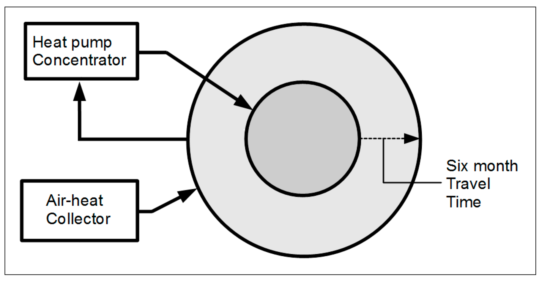
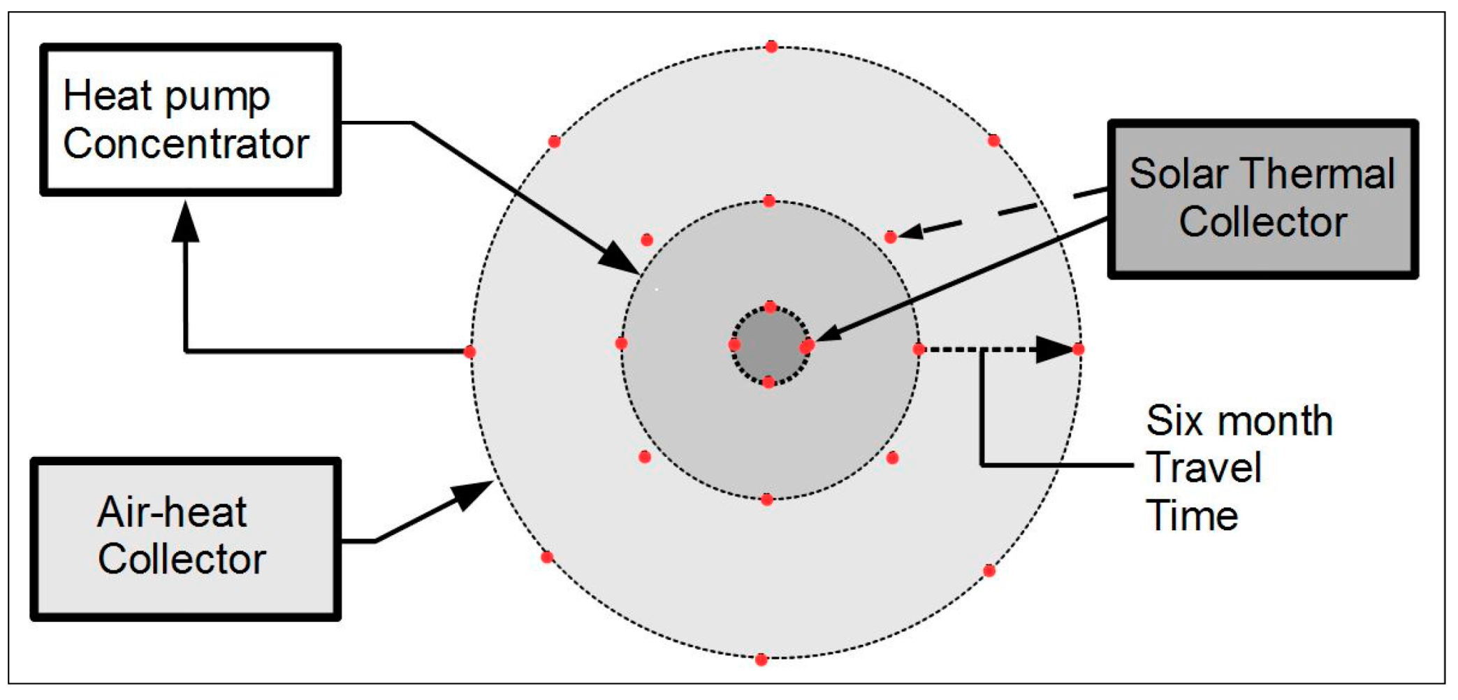
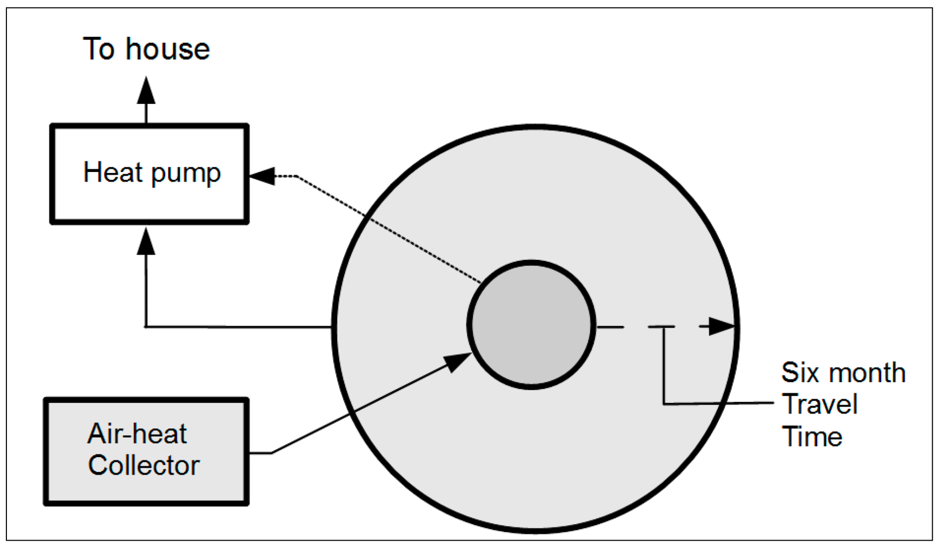
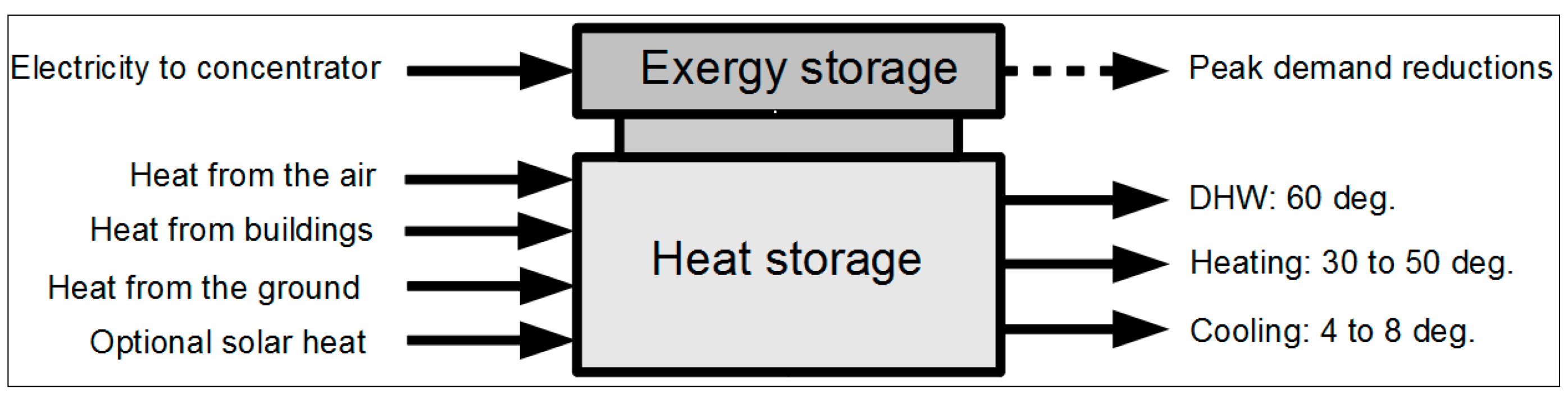
2. Concept


3. The Four Local Thermal Energy Sources
- (a)
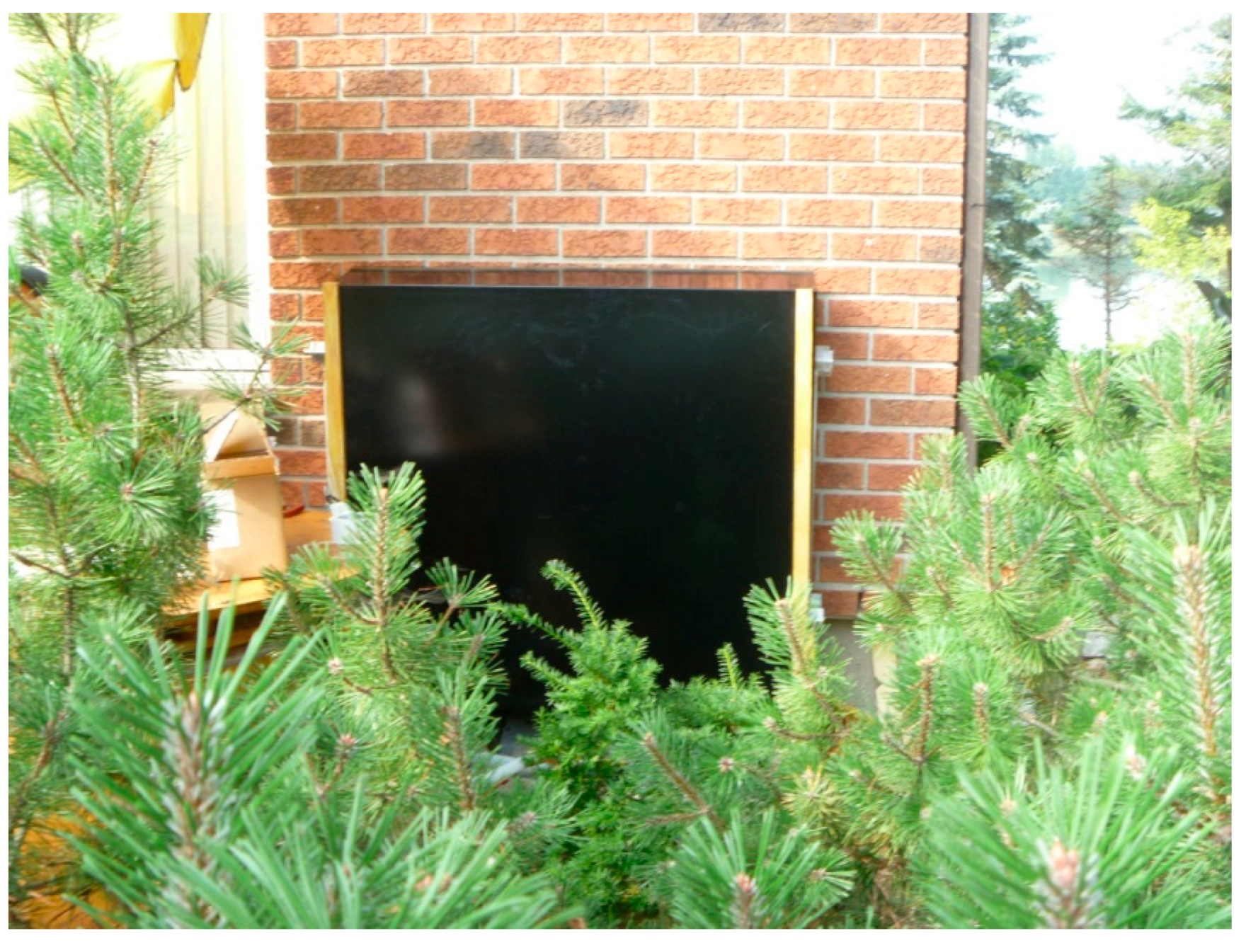
- Solar heat. A heat pump that is using heat that is extracted from the ground at 8 degrees cannot readily raise the central temperature to the 60 degrees C that is needed for DHW. However, conventional solar thermal collectors are suitable for that task, and they operate very efficiently in this application because their excess output in the summer contributes to the heat that is stored for space heating. Moreover, the hot solar-heated core provides a large reserve of heat that can be used to boost the space heating capacity on very cold winter nights.
- (b)
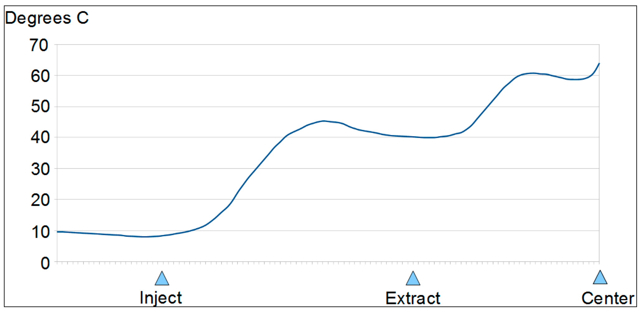
- Heat from the air conditioning system. This needs a heat sink that operates at 4 to 8 degrees. Normally the loop for the outer boreholes operates at 8 degrees but when hot weather is expected the control system can be used to temporarily drop the loop temperature to 4 degrees. Since the change is only temporary it will not significantly affect the peripheral temperature.
- (c)
- Heat from the summer air. This is a virtually unlimited source of energy that is easy to exploit in this kind of system because the outer ring, into which the heat from the air-source heat exchangers is to be deposited, is always at a low temperature.
- (d)
- Natural heat from the ground. This provides insurance against situations where the amount of injected heat is exhausted for reasons that were unforeseen. There are some applications in which natural ground heat would be useful as a major energy source.

4. Reducing Power Demand Fluctuations
- (a)
- The generation system does not need to handle large peak loads and it does not need to maintain a large excess in capacity in order to handle unanticipated demands. At the present time the available generation capacity in Ontario is commonly more than 10,000 MW greater than the actual rate of consumption. Reducing the need to maintain a large generation capacity in order to cope with the possible peak demands would reduce the capital cost of the generation facilities.
- (b)
- The productivity of the nuclear, hydro and wind stations could be improved because their potential nighttime output would be profitably employed.
- (c)
- Stabilizing the daily and seasonal demands would stabilize power prices, eliminating the substantial price fluctuations that often occur at the present time.
- (d)
- Reducing the demand fluctuations and employing local storage reduces the cost and complexity of the power distribution grid.
5. Design Considerations
5.1. Space Heating
5.2. DHW
5.3. Cooling
6. Scope for Applications

| Application and Building Type | PJ/Year |
|---|---|
| Electricity used for heating in residential sector | 36.4 |
| Electricity used for heating in commercial/institutional sector | 14.5 |
| Electricity used for cooling in residential sector | 16.1 |
| Electricity used for cooling in commercial/institutional sector | 31.9 |
| Electricity used for water heating in residential sector | 9 |
| Electricity used for water heating in commercial/institutional | 2.3 |
| Total electricity used for thermal applications in 2011 | 110.2 |
| Application and Building Type | PJ/Year |
|---|---|
| Total energy used for heating in residential sector | 339.6 |
| Total energy used for heating in commercial/institutional sector | 119 |
| Total energy used for cooling in residential sector | 16.1 |
| Total energy used for cooling in commercial/institutional sector | 33.9 |
| Total energy used for water heating in residential sector | 110.2 |
| Total energy used for water heating in commercial/institutional sector | 38.3 |
| Total energy used for thermal applications in 2011 | 657.1 |
| Potential Source of Extra Electricity Generation | PJ/Year |
|---|---|
| Surplus baseload hydro (OPG data) | 4 |
| Surplus baseload hydro from other hydro sites (projected) | 2.7 |
| Surplus power dumped via exports | 65.6 |
| Surplus wind power | not available |
| Unused nuclear capacity 1 | not available 1 |
| Total | 72.3 |
7. Conclusions
Acknowledgments
Author Contributions
Conflicts of Interest
References and Notes
- IESO. Available online: http://www.ieso.ca (accessed on 21 July 2014).
- Tolmie, R.; Rosen, M.A. Exergy Storage in the Ground,3rd World Sustainability Forum. Available online: http://www.sciforum.net/conference/wsf3 (accessed on 21 July 2014).
- Data of Residential Sector–Ontario (Res: Table 1). Available online: http://oee.nrcan.gc.ca/corporate/statistics/neud/dpa/showTable.cfm?type=CP§or=res&juris=on&rn=1&page=4&CFID=34745232&CFTOKEN=2e44cf1767dc1118-AD9CE054-ABBA-9D79-87EF863FD6CD9FBF (accessed on 14 November 2014).
- Data of Commercial/Institutional Sector–Ontario (Com/Inst: Table 1). Available online: http://oee.nrcan.gc.ca/corporate/statistics/neud/dpa/showTable.cfm?type=CP§or=com&juris=on&rn=1&page=4&CFID=34745232&CFTOKEN=2e44cf1767dc1118-AD9CE054-ABBA-9D79-87EF863FD6CD9FBF (accessed on 14 November 2014).
- Dincer, I.; Rosen, M.A. Thermal Energy Storage. In Systems and Applications, 2nd ed.; Wiley: London, UK, 2011; Chapter 6. [Google Scholar]
- Coefficient of Performance. Available online: http://en.wikipedia.org/wiki/Coefficient_of_performance (accessed on 21 July 2014).
- Drake Landing District Heating. Available online: http://www.dlsc.ca/district.htm (accessed on 21 July 2014).
- Tolmie, R. Concentric Ring Heat Exchangers. GeoExchange Coalition/CANSIA workshop: Toronto, ON, Canada, January 2013. [Google Scholar]
- Data of Residential Sector–Ontario (Res: Table 4). Available online: http://oee.nrcan.gc.ca/corporate/statistics/neud/dpa/showTable.cfm?type=CP§or=com&juris=on&rn=4&page=4&CFID=34745232&CFTOKEN=2e44cf1767dc1118-AD9CE054-ABBA-9D79-87EF863FD6CD9FBF (accessed on 14 November 2014).
- Data of Residential Sector–Ontario (Res: Table 5). Available online: http://oee.nrcan.gc.ca/corporate/statistics/neud/dpa/showTable.cfm?type=CP§or=com&juris=on&rn=5&page=4&CFID=34745232&CFTOKEN=2e44cf1767dc1118-AD9CE054-ABBA-9D79-87EF863FD6CD9FBF (accessed on 14 November 2014).
- Data of Residential Sector–Ontario (Res: Table 10). Available online: http://oee.nrcan.gc.ca/corporate/statistics/neud/dpa/showTable.cfm?type=CP§or=com&juris=on&rn=10&page=4&CFID=34745232&CFTOKEN=2e44cf1767dc1118-AD9CE054-ABBA-9D79-87EF863FD6CD9FBF (accessed on 14 November 2014).
- Data of Commercial/Institutional Sector–Ontario (Com/Inst: Table 2). Available online: http://oee.nrcan.gc.ca/corporate/statistics/neud/dpa/showTable.cfm?type=CP§or=com&juris=on&rn=2&page=4&CFID=34745232&CFTOKEN=2e44cf1767dc1118-AD9CE054-ABBA-9D79-87EF863FD6CD9FBF (accessed on 14 November 2014).
- Data of Commercial/Institutional Sector–Ontario (Com/Inst: Table 24). Available online: http://oee.nrcan.gc.ca/corporate/statistics/neud/dpa/showTable.cfm?type=CP§or=com&juris=on&rn=24&page=4&CFID=34745232&CFTOKEN=2e44cf1767dc1118-AD9CE054-ABBA-9D79-87EF863FD6CD9FBF (accessed on 14 November 2014).
- Data of Commercial/Institutional Sector–Ontario (Com/Inst: Table 26). Available online: http://oee.nrcan.gc.ca/corporate/statistics/neud/dpa/showTable.cfm?type=CP§or=com&juris=on&rn=26&page=4&CFID=34745232&CFTOKEN=2e44cf1767dc1118-AD9CE054-ABBA-9D79-87EF863FD6CD9FBF (accessed on 14 November 2014).
- Data of Residential Sector–Ontario (Res: Table 2). Available online: http://oee.nrcan.gc.ca/corporate/statistics/neud/dpa/showTable.cfm?type=CP§or=res&juris=on&rn=2&page=4&CFID=34781935&CFTOKEN=a3e4b094504b4fd5-C1ABC796-0C01-8974-3372515F5BDA14BA (accessed on 14 November 2014).
© 2014 by the authors; licensee MDPI, Basel, Switzerland. This article is an open access article distributed under the terms and conditions of the Creative Commons Attribution license (http://creativecommons.org/licenses/by/4.0/).
Share and Cite
Tolmie, R.; Rosen, M.A. A Dual Function Energy Store. Sustainability 2014, 6, 8297-8309. https://doi.org/10.3390/su6118297
Tolmie R, Rosen MA. A Dual Function Energy Store. Sustainability. 2014; 6(11):8297-8309. https://doi.org/10.3390/su6118297
Chicago/Turabian StyleTolmie, Ron, and Marc A. Rosen. 2014. "A Dual Function Energy Store" Sustainability 6, no. 11: 8297-8309. https://doi.org/10.3390/su6118297