1. Introduction
Sustainability requires balance between humans and the environment to meet our needs today without compromising the resources available for future generations. According to the International Energy Outlook report [
1], the world energy consumption will grow by 56% between 2010 and 2040. The transportation sector, which is the second largest energy consuming sector after industrial production, plays an important role in this increase. The transportation sector’s share of the world’s total liquids consumption increased from 50% in 2002 to 53% in 2007 and is projected to reach 61% in 2035 accounting for 87% of the total increase. Several studies indicate that the transportation sector is globally responsible for nearly 23% of the world’s energy-related CO
2 emissions. This amount will be increased nearly 35% in 2030 due to both population and economic growth. In addition, road transportation, which is the biggest part of transportation, is responsible for 10% of greenhouse gas emissions worldwide. If preventive measures are not taken, the amount of greenhouse gases from the transport sector is expected to increase by 50% in 2030 and 80% in 2050 [
2,
3,
4].
Recently, there have been growing concerns over fuel consumption and pollution caused by the increasing number of automobiles, and the automotive industry is under great pressure to reduce fuel consumption and emissions. The shortages of energy sources and global warming have put increasing pressure on the investigation of new materials and the development of new products and technologies for the automotive industry. There are a number of approaches for improving vehicle energy efficiency and lowering emission rates. These approaches include drive train efficiency improvements, alternative fuel systems, downsizing engine capacity with turbocharging or supercharging, aerodynamic design and vehicle weight reductions [
5,
6,
7].
Among these technologies, reducing structural weight is one of the most important ways of reducing fuel consumption and improving the performance of vehicles. Weights have increased recently due to some specific demands of passenger comfort and safety procedures. In addition to these issues, some of the legal engine requirements concerning emission rates and accordingly engine systems will add extra loads to the mass transit vehicles. Fuel economy and greenhouse gas emission standards have proven to be one of the most effective tools in controlling fuel demand and greenhouse gas emissions; there is therefore great societal and legislative pressure motivating automotive weight reduction [
8,
9].
Approximately 75% of the average motor vehicle’s fuel consumption is directly related to factors associated with vehicle weight. Vehicle weight affects handling, braking and reducing power requirements. It is also the first step toward the downsizing of other vehicle components. Ungureanu
et al. [
10] stated that vehicle weight is the key source to achieve significant reductions in the life cycle energy consumption and greenhouse gas emissions because the rolling resistance and acceleration forces, which are the essential elements of transportation energy efficiency, are directly proportional to vehicle weight.
Several studies have been conducted on the relation between vehicle weight reduction and fuel consumption. Kobayashi
et al. [
11], Bastani
et al. [
12] and Mayyas
et al. [
13] investigated fuel consumption and greenhouse gas emissions depending on the vehicle type and weight reduction. The results indicated that a 10% reduction in vehicle weight can result in a 6%–8% fuel economy improvement. Reducing vehicle weight has other benefits as well, such as allowing vehicles to carry advanced equipment or increasing available space in the vehicle without adding weight. These authors also indicated that lightweighting is important for improving the efficiency and range of hybrid electric, plug-in hybrid electric and electric vehicles, thus allowing for compensation for the weight of power system components such as batteries and electric motors.
In particular, the effect of the lightweighting of mass transit vehicles on fuel consumption is quite remarkable. Helms
et al. [
14] provided a comprehensive overview on use phase energy savings for different transport vehicles. These authors investigated specific energy savings per 100 kg weight reduction and vehicle 100 km for different vehicle types and stated that there is a great potential for energy savings via weight reduction for buses and coaches.
1.1. Material Selection Criteria for Lightweighting
Lightweighting is an integrative technique that utilizes all fields of optimized design, manufacturing techniques and suitable material selection. It is a technique to reduce the mass of an entire structure and its single elements while increasing the functional quality. Cheah
et al. [
15], Lutsey [
16], Witik
et al. [
17] stated that reductions in weight can be achieved by a combination of (i) material substitution, in which conventional materials in automotive engineering such as steel, plastic and iron are replaced with lighter and special alternatives such as aluminum, magnesium, high strength steel and composite, (ii) innovative design where parts are optimized via computer-based programs and optimization techniques to achieve higher performance and (iii) vehicle downsizing.
Material substitution is the key method for lightweighting. A successful material selection process is only possible through an optimized and balanced solution between cost reduction and improved comfort and safety in accordance with new legislation concerning environmental aspects.
Several methodologies exist for incorporating environmental concerns in the material selection process in the automotive industry. Life Cycle Assessment (LCA), Life Cycle Costing (LCC) and Life Cycle Optimization (LCO) are being used to assess new vehicular structures from sustainability and design viewpoints for environmental perspectives [
18,
19]. The most important methodology is LCA which evaluates the environmental impact of a given product over its entire life cycle. This methodology can be divided into three main phases: the production phase, including the energy requirements for any primary and secondary materials used and all the processes involved in manufacturing these materials into a finished product; the operation phase, including the energy, fuel and emissions over the entire lifetime; and the end-of-life phase, comprising the energy used in the disposal of the discarded product and whatever energy is gained from its recycling [
20].
Several researchers have calculated the environmental impact of the material selection and LCA of the automotive applications. Giudice
et al. [
21] developed a method that introduced environmental considerations in the selection of the materials used in components, meeting functional and performance requirements while minimizing the environmental impact associated with the product’s entire life cycle. Ermolaeva
et al. [
22] investigated the optimal material selection according to the constructed system based on the best potential of each material candidate in mechanical behavior under a given load and boundary conditions and stated that steel is the best candidate for heavily loaded structures. Fitch and Cooper [
23] presented a method of performing life cycle energy analysis for material selection that applied product analysis methods to the evaluation of material options for automotive components. These authors stated that glass fiber composites and high strength steel beams result in the lowest life cycle energy consumption. The World Auto Steel Organization investigated the effects of several materials (steel, aluminum, composite and AHSS) on LCA for different combination of vehicle bodies and powertrains. This study indicated that using AHSS steel generates much less environmental damages in terms of greenhouse gases than mild steel or aluminum [
24].
Cost is the other important driving force in material selection. There is a trend toward reducing tooling and producing costs, increasing flexibility in manufacturing methods and shortening cycle times. The automotive industry is willing to use low investment cost materials for faster and less expensive tooling and processing. Today, traditional materials such as steel and aluminum still play a significant part in automotive applications. Improvements in the quality of casting metals and processing technologies have been leading to improved strength and reduced wall thickness, leading to lightweight and more reproducible components [
25].
Ferrão and Amaral [
26] analyzed the manufacturing costs of fabrication and assembly for aluminum and steel auto bodies for two different vehicle types. These authors stated that higher material and tooling costs are key obstacles for aluminum automotive panels. Ungureanu
et al. [
27] developed a sustainability evaluation methodology for computing the potential benefits of using lighter materials, such as aluminum, in auto body applications. They stated in their study that the current equipment and processes are well suited for steel based components and a complete redesign of this equipment and processes would be needed to manufacture aluminum components. Using mostly dual-phase steel, the International Iron and Steel Institute’s Ultralight Steel Auto Body (ULSAB) Program demonstrated mass savings of 25% for a C-class (compact) car’s body structure. HSS is an attractive nearer-term option, due to its relatively low cost and accessibility [
28].
In comparing candidate materials that can be used in the automotive industry, aluminum and HSS are the most cost effective at large production volume scales, and their increasing use in vehicles is likely to continue. Cast aluminum is most suited to replace cast iron components, stamped aluminum for stamped steel body panels, and HSS for structural steel parts. Composites are also expected to replace some steel in the vehicle but to a smaller degree given high cost inhibitions [
29].
Various results have been obtained using composite, high strength steel, aluminum and magnesium for lightweighting automotive parts in the literature. Several major studies, as well as some automakers’ announced plans, indicate that nearly 20% weight reduction could be achieved with small additional costs in the next 5–10 years with material substitution [
16,
29,
30,
31,
32]. In addition, many studies note that the amount of lighter materials in vehicles has progressively increased over the past decades [
33,
34,
35]. There have been many international and multidisciplinary projects that have aimed to improve vehicle energy efficiency and lightweighting vehicle parts [
36,
37,
38,
39].
Lightweight materials have been increasingly used in transportation vehicles due to their excellent mechanical properties. Especially in public transport vehicles, their use helps to reduce weight and therefore improves fuel efficiency, which translates into long-term cost savings. There are various applications to decrease the weight of mass transit vehicle structures by replacing the body structure or individual components with lightweight materials. Much weight reduction has been achieved by material substitution and innovative design techniques in several parts [
30,
40,
41,
42,
43].
1.2. Safety Regulations for Commercial Vehicles
Regulations are needed for commercial vehicles to ensure safety, reduce harmful accidents and determine the minimum technical conditions in parts of the vehicles. Because of these necessities technical standards are necessary for vehicle manufacturers. During the manufacturing phase of vehicles, corresponding offices of the countries are authorized to legislate for motor vehicle type approval directives and other regulations connected with these directives. Vehicles can only be manufactured after this procedure.
Passenger transportation in terms of buses and coaches is very safe. Statistical comparisons with other transport types demonstrate the high safety level, which is much higher than that of personal vehicles. Despite the high safety rating, when these vehicles are involved in a severe crash, the number of casualties is usually high due to the large number of occupants travelling in these vehicles. The safety of the occupants according to side, rear, and frontal crashworthiness and rollover accidents has become an important issue for bus manufactures and customers. Therefore, the structural stability of the vehicle should be evaluated according to the regulations before the manufacturing phase. There are various projects with an aim to improve the safety of road transportation. One of these projects is the “Enhanced Coach and Bus Occupant Safety” (ECBOS) project funded by the EU. This project was established to study improvements in current regulations and propose new standards for the development of safer buses and coaches [
44].
One of the most fatal accidents of buses and coaches is the rollover crash. In the case of a rollover, passengers run the risk of being exposed to ejection or intrusion and thus exposed to a high fatality risk. Therefore, the rollover strength has become an important issue for bus and coach manufacturers. Today, the European regulation “ECE-R66” is in force to prevent rollover accidents, thereby ensuring the safety of bus and coach occupants. According to the ECE R66 regulation, a safety (residual) space is secured against the deformation of the vehicle structure during or after the rollover. The rollover test is conducted to ensure that the external parts of the bus (pillars, safety rings, luggage racks
etc.) are not penetrating or intruding into the residual space. If penetration or intrusion occurs, then the test is considered to have failed [
45]. According to the ECE R66 regulation, the certification can be gained in four different ways: a complete bus rollover test, a bay section rollover test, a pendulum test and a numerical simulation of a rollover. The selection between these tests is completely up to the coach manufacturer. During a rollover crash, one of the most important components that greatly affects the movement of the passengers inside the vehicle is the seat. Therefore, the structural stability of the seat and restraints is important for occupant safety. However, due to this regulation being provided by bus manufacturers, this type of verification is beyond the scope in this study.
Seats with restraints are one of the most important components of minimizing the injury risks of occupants when a crash occurs. Passenger seats must meet many safety regulations set by different government agencies. Seats must protect the occupant from a crash impact; therefore, to measure the safety requirements, seats are tested for their strength and deflection in the event of a vehicle crash. In these tests, high forces are applied to the seat structure with various devices and systems. All the components of the seat and anchorages must resist the defined loads without damage. The whole parts of the seat should have enough stiffness for structural stability. Each manufactured seats must pass these validation tests.
One of the important regulations related to passenger seats is ECE R80 [
46]. This regulation deals with the strength of the seat, their anchorages and any head restraints. There are two types of tests that verify this regulation. One of these tests is the dynamic crash test. In this test, the seat with whole equipment is connected to a rigid platform that has the same specialties as the vehicle basement. The auxiliary seat, which has the same specification as the seat being tested, is located parallel to and behind the seat being tested. After fixing the seats on trolley (rigid platform), a crash test dummy is placed on the auxiliary seat and the trolley is activated. The other test in this regulation is the static test. The aim of this test is to determine whether the seat occupants are correctly retained by the seats in front of them. After the test period for verification, the seat should remain firmly held, even if one anchorage is detached, and all the locking systems should remain locked during the test. In addition, no structural part of the seat or accessories can have any break or sharp edges that can cause any injury [
46].
ECE R14 is the most important regulation to provide for passenger safety. This regulation must be passed to ensure a correct functionality and sufficient strength of all anchorage points of the seat and seatbelts [
47]. Depending on the location on the vehicle, some seats have a three-point seatbelt and some have a two-point seatbelt. To guarantee the seatbelt system and anchorages, they must resist defined static test loads. These high forces are applied to the seatbelts over loading devices with the help of body blocks. After the test, the seatbelt and anchorages are expected to retain their integrity. In addition, when the forces are applied to the top of the seat, longitudinal displacement must not exceed the allowed scale. The forces applied to the seatbelt are determined by the vehicle class (M2 or M3 class) and seatbelt point number. The forces that must be applied according to the vehicle class and seatbelt point number are given
Table 1. In this study, ECE R14 regulation is considered because this regulation has the most critical effect on the passenger seats and restrains in the verification phase.
Table 1.
ECE R14 test loads.
Table 1.
ECE R14 test loads.
| Vehicle Class | Seatbelt Point Type | Shoulder Block Pull Force (N) | Lap Block Pull Force (N) |
|---|
| M2 (m < 5000 kg) | 2 point | - | F = 11,000 N + (10 x mseat x 9,81m/s2) |
| M2 (m < 5000 kg) | 3 point | F = 6750 N | F = 6750 N + (10 x mseat x 9,81m/s2) |
| M3 (5000 kg < m) | 2 point | - | F = 7400 N + (6,6 x mseat x 9,81m/s2) |
| M3 (5000 kg < m) | 3 point | F = 4500 N | F = 4500 N + (6,6 x mseat x 9,81m/s2) |
Several researchers have investigated the effect of the seat and restraint systems as well as structural behavior in a crash accident to evaluate the structural resistance and passenger injury risks. Guler
et al. [
48] investigated the effect of the seats and restraint systems as well as the structural behavior in a rollover accident to evaluate the structural resistance and passenger-injury risks. Guler
et al. [
49] stated that seat structures absorb significant energy and help the pillars to yield less deformation during a rollover accident. Belingardi
et al. [
50] stated that it is necessary to accurately describe the structural behavior of the seat during the rollover as the correct description of the seat deformation to properly evaluate the movement of the passenger inside the vehicle. To examine the effect of the seat structure, Elitok
et al. [
51] performed ECE R66 analysis with the seat structure and stated that the seat structure has a positive effect of approximately 20% on bending deformation behavior. Hessenberger [
52] compared two different analysis types that meet the ECE R14 regulation for passenger seats.
Recently, several studies have been conducted on seat lightweighting considering the safety requirements. Hojnacki [
53], Polavarapu [
54], and Thiyagarajan [
55] used finite element analysis and topology optimization to design lightweight automotive seat structures. Their studies revealed that the seat fulfills the criteria of the ECE R17 safety test and weight reductions of 13%–20% were obtained. Material substitution is the other method selected by several researchers. Yuce [
56], Gleich
et al. [
57] and Bartus
et al. [
58] achieved weight reductions of the seat structures using high strength steel and composites. Additionally, these researchers proclaimed cost savings due to high quality surfaces and reduced part complexity. Furthermore, the Low Carbon Vehicle Technology Project (LCVTP), the CAMISMA (Carbon fiber-/Amid-/Metallic Structural Interior Component using a Multi-Material Approach) and ACC (Automotive Composites Consortium) are some international projects that aimed at lightweighting the seat structure. In these studies, researchers manufactured lightweight seat structures using different materials and manufacturing techniques. Several weight reductions were achieved in these studies without compromising safety criteria [
37,
38,
59].
1.3. Conventional Passenger Seat
Passenger seats play an important role for transportation due to the comfort and safety of the occupant while traveling. The primary duty of a seat is to provide seating space for the passengers. In addition, the passenger is subjected to various forces in a crash event and, therefore, the seat must protect the occupant. Seats should also absorb vibration and noise for comfortable travelling. Consequently, a seat design should look smart, be lightweight and meet safety requirements. The development of passenger seats in the medium term will continue to be a competition between requirements of safety, comfort, low costs and lightweighting.
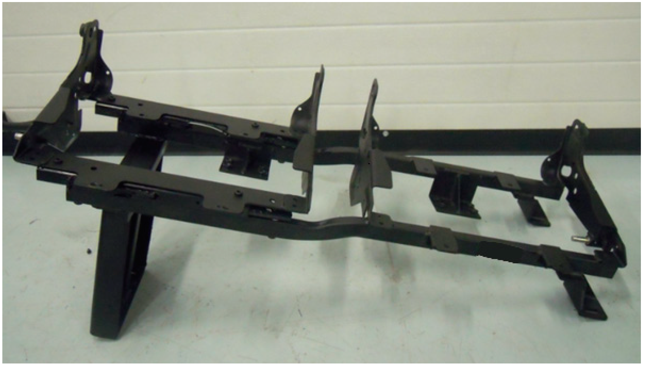
The conventional passenger seat structure essentially consists of three main components; a structural framework for carrying load, a chassis with a pillar to provide the shape and strength of the seat and foam with fabric, which provides occupant comfort and ergonomic driving conditions.
The seat chassis is the most crucial part of the passenger seat (
Figure 1) and consists of cushions and a seat pillar. Conventionally, the seat chassis is made of St-37 steel profiles with thicknesses of 2.5 mm. The function of the seat chassis is to provide structural rigidity to the seat and act as a support platform for the backrest frame. The seat cushion with foam represents occupant travel comfort and is attached with screws and brackets to the seat chassis. In addition, the seat pillar is welded to the chassis. During an accident or ECE regulation tests, considerable loads act on the chassis due to the seatbelt connection points, which are located in the middle of the chassis.
The pillar is the other important part of the seat (
Figure 1) and attaches the seat structure to the vehicle basement. Typically, the pillar is made of St-37 sheet metal and is welded to the seat chassis. Depending on the vehicle basement type, some passenger seats have two pillars and others have only one pillar, with the other side of the seat being attached to the vehicle sidewall. Generally pillars are mounted to the vehicle basement with bolts.
Figure 1.
A view of a typical seat chassis with pillar.
Figure 1.
A view of a typical seat chassis with pillar.
The backrest frame is one of the important parts of the seat and consists of steel profiles whose thicknesses depend on the safety requirements. Thin hardboard with foam and a backrest frame make up the seat back. In three-point seatbelts, one of the connecting points of the belt is on the backrest frame. Thus, this frame must be designed for structural rigidity and strength. The conventional backrest frame is composed of St-37 steel and is mostly connected to the chassis by welding.
Due to requirements for long journeys, passenger seats have been developed to be relatively complex and heavy and to offer numerous comfort functions and many mechanical and electrical features (e.g., backrest angle adjuster, recliner and slide mechanism). Depending on the vehicle class some other features such as an armrest, service table, footrest, heating systems and multimedia equipment can be mounted on the seat. The increasing functional requirements of safety, comfort and technology parameters for passenger seats have increased the complexity and weight of the seat.
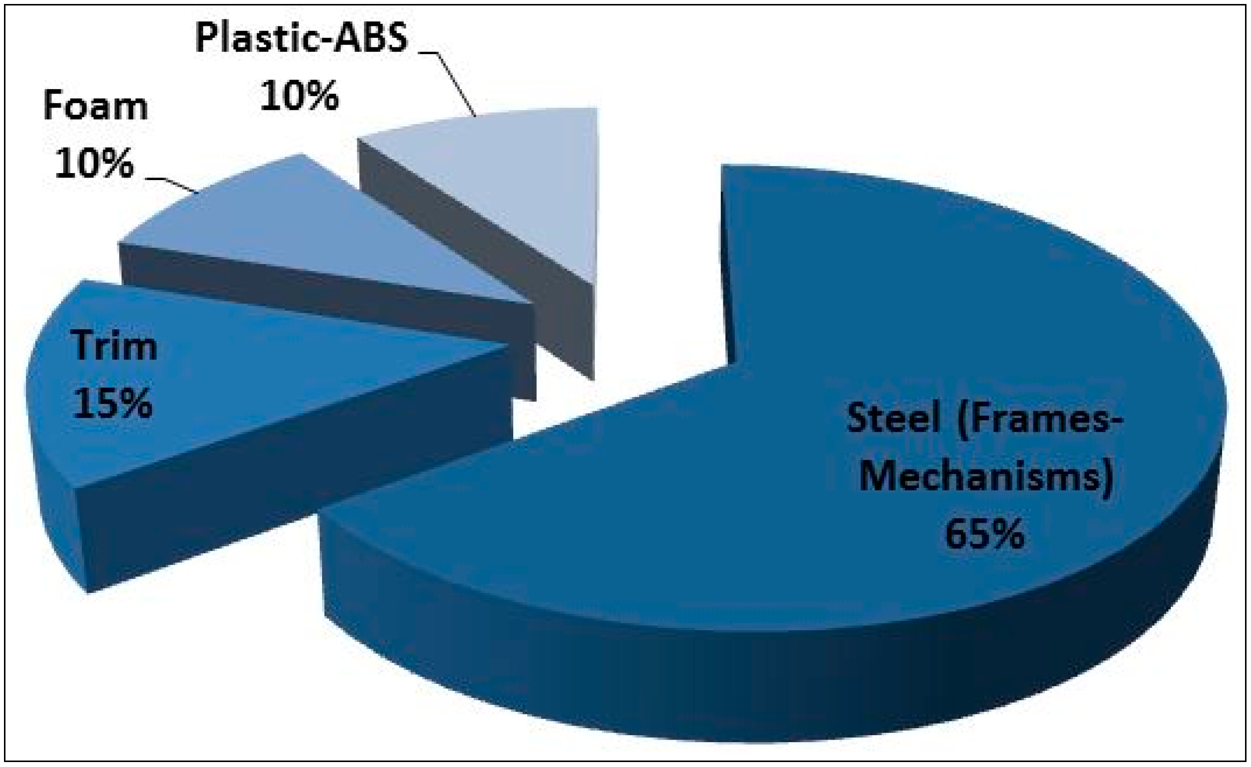
Figure 2 shows the weight distribution of a typical passenger seat.
Figure 2.
Typical passenger seat weight distribution.
Figure 2.
Typical passenger seat weight distribution.
1.4. Motivation and Objectives
Public transportation has many advantages over modes of transport, particularly in terms of safety, environmental impact and flexibility. Public transportation performed by bus, coach and light commercial vehicles is increasing rapidly worldwide and specifically in the European Union (EU). In 2010, EU citizens travelled approximately 13,000 miles per capita, and nearly 8% of this travel was by buses and coaches. Bus and coach travel combined accounted for 539 billion passengers, the highest share of any surface mode of public transportation. Especially in Turkey, the demand for public transportation is very high. Approximately 45% of Turkey’s population travel by coach and bus. Thus, the largest numbers of passenger kilometers classified as coach are in Turkey within the EU and its 13 neighboring states [
60].
Public transport vehicles (buses, coaches, minibuses) offer outstandingly high energy savings with lightweighting among the other road vehicles due to highest energy savings being observed for vehicles that employ frequent stops and accelerations. Among the road vehicles, city buses offer remarkably high lifetime energy savings mainly due to the combination of a high lifetime performance and high specific energy savings [
61]. Therefore weight reduction is quite important for these vehicles.
Due to the ratio of overall vehicle weight, passenger seats offer outstanding energy savings potential in mass transit vehicles. Passenger seat numbers and placements depend on the vehicle class. M2 class vehicles (minibuses, light commercial vehicles) have 10–18 passenger seats and M3 class vehicles (buses, coaches) have 30–55 seats per vehicle. With these numbers, seats play an important role in the vehicle weight, being responsible for nearly 8% of the overall vehicle weight in buses. Therefore, weight reduction is a factor of growing importance, and the suppliers of seats are heavily obligated to develop lightweight seat structures that retain optimum safety. Passenger seats are one of the major contributors of the total vehicle weight especially in mass transit vehicles. Therefore, lightweighting the seat structure will have a profound effect on commercial vehicle fuel consumption, thereby contributing to the goal of sustainable transport.
The primary objective of this study is to design and prototype lightweight passenger seats for buses and coaches according to the ECE R14 regulation without compromising any comfort criteria. The seat structure is considered as the area of research that presents the best opportunity for weight reduction using new materials and design techniques. With the help of the reduced thickness high strength steel profiles and pipes, a 20% weight reduction is intended for the entire seat structure. In addition, a reduction of the number of parts is targeted.
2. Method
Computer-aided design (CAD) and finite element analysis (FEA) is accepted across a wide range of industries as a crucial tool for product design and optimization. These tools are essential to accurately predict the safety performance of automotive parts in the event of a crash. When designing a passenger seat, most of the variables to be considered relate to either geometry or materials. A valuable tool for facilitating and shortening this complex design process is numerical simulation using FEA. Modeling the seats in a virtual environment integrates CAD with material databases and allows the input and evaluation of various loads and stresses without the time constraints of real tests. FEA can predict the response of a particular design under specific conditions and provide data that can be used in the design phase. Traditionally, bench tests have been used to investigate the structural behavior of prototype products and to develop new products. However, such tests are time consuming and expensive. FEA reduces the prototype costs and makes the correct design possible before the bench test.
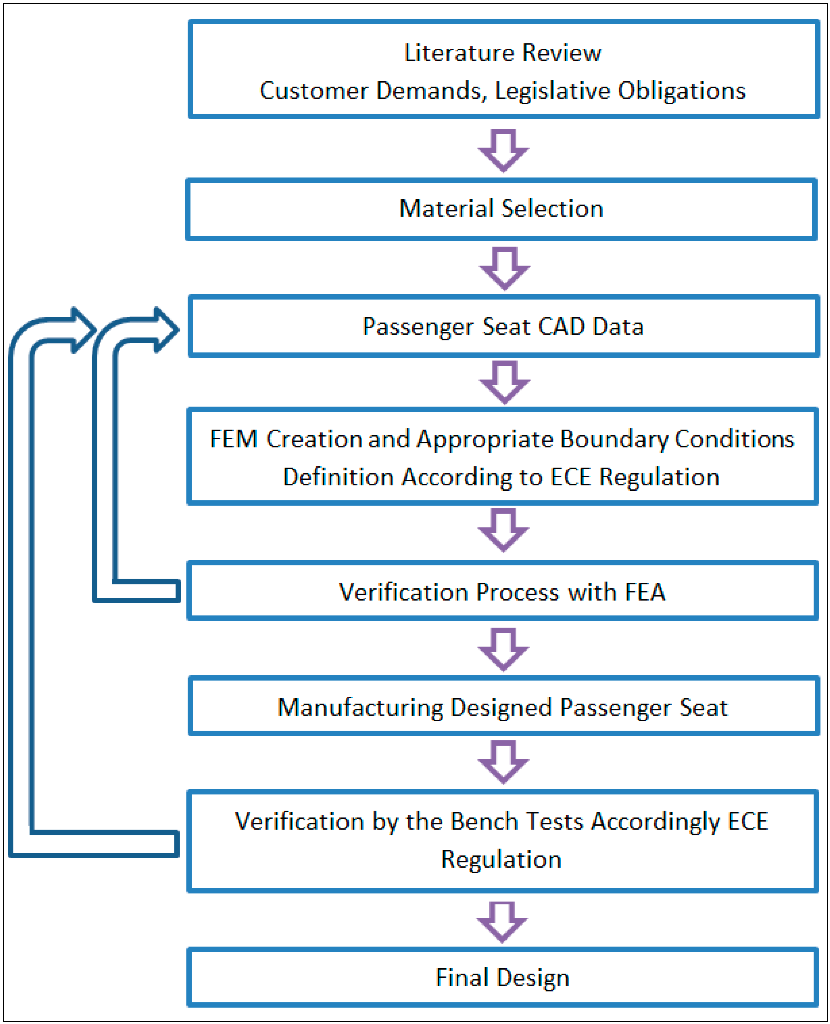
This study consists of three main phases. At the beginning, a literature review related to passenger seat design and appropriate material selection was undertaken. Additionally legislative obligations regarding passenger seat safety were investigated. The reference methodology (
Figure 3) was followed in this study.
Figure 3.
Flowchart of the seat design.
Figure 3.
Flowchart of the seat design.
One of the important phases of the study was material selection. To select appropriate materials, several performance indicators were considered. Strength of the material was the most effective criterion for structural stability of the seat. Due to desired reduction of the weight, being lightweight was the second. Formability with required tolerances was another performance indicator of the material selection. Additionally, low cost and accessibility of the material were taken into consideration.
Considering the performance indicators defined above, high strength steel was the first candidate material for lightweighting the structure because this material has by far the largest share of the market due to its ease of manufacturing, accessibility and low cost. Alternative materials such as aluminum, magnesium and composites are certainly more costly than the currently used steel that they may replace. Additionally, this replacement faces some obstacles, especially in the manufacturing process. The direct replacement of mild steel structures with high strength steel without any design optimization has been used for lightweighting. With its high formability, high strength steel allows for the design of complex parts and hence difficult forming operations. High strength steel offers reasonable freedom to the designer as less manufacturing restrictions are encountered. Improvements in quality processing technologies have been leading to improved strength and reduced wall thickness, leading to its being lightweight. Cost is the other important driving force for the material selection. High strength steel offers low cost when compared with alumınum and composites, especially on large production scales. Additionally, the current manufacturing facilities (forming, welding etc.) are highly suitable for steel and their availability is vast. Bending the pipes used in the backrest frame and welding operation between pillar and chassis were also critical issues for the prototype seat manufacturing. In this study, considering these performance indicators, high strength steel was preferred.
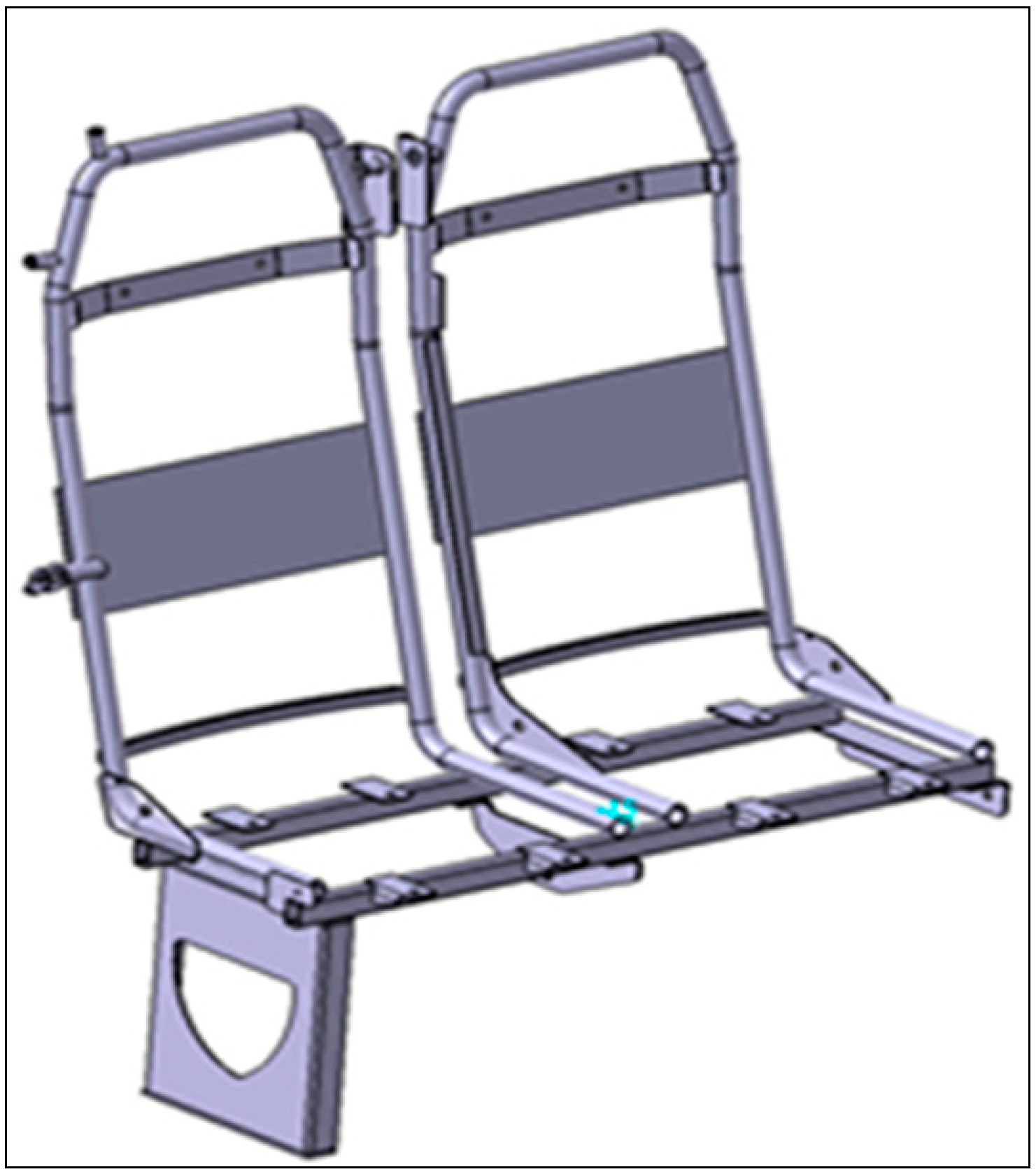
The second phase of this study consisted of the conceptual design stage of the passenger seat, which was determined by customer-specific demands, vehicle class, basement type and safety standards. A solid model of the prototype seat was developed in three-dimensional views for simulation purposes. The seat design should be modular to be appropriate for many vehicle basements with an adjustable pillar distance. In addition, appropriate material and production techniques must be considered. With the help of the existing seat designs, the prototype passenger seat CAD model was completed (
Figure 4).
Figure 4.
CAD data of the seat structure.
Figure 4.
CAD data of the seat structure.
During the design phase of the passenger seat, several parameters were considered, such as weight reduction, manufacturability and safety requirements. The new concept was designed with a three-point seatbelt for occupant safety. Instead of a traditional profile frame, the backrest was designed with high strength steel pipe, with a thickness of 2 mm. Thanks to the new design, which increased the rigidity of the backrest frame, additional supporting parts were not required. Thus, the number of seat parts was reduced. Furthermore, conventional backrest frames consist of profiles and are not suitable to every bending radius. The ease of manufacturing of the new structure was provided by the steel pipes. This frame was designed to connect the chassis front and rear profile with screws; therefore, the new design is more modular and can be used with different chassis types.
The other improvement that was achieved was the cushion part design. The cushion part, which previously consisted of a plastic cover, brackets and foam, in the new design consists of foam and plastic without brackets. This cushion also provides the same ergonomic comfort and passed cushion foam fatigue tests. During the design phase, seat chassis consisted of profiles with thicknesses determined by the FEA. Consequently, the new seat design reduces the number of parts compared with conventional structures without compromising comfort or safety criteria. Additionally, new design has gained ease of manufacturing and aesthetic appearance.
The third main phase of the study was verification. This phase comprises two different verifications: finite element analysis and bench tests. To verify the functional performance of the CAD design and to determine if the safety requirements were satisfied, finite element models of the seat frame were created. For the finite element model of the seat, four different profile thicknesses (1, 1.5, 2, and 2.5 mm) were tested for the chassis. In selecting the thicknesses, several parameters were considered. Due to profiles on the market having standard thicknesses, selected profile thicknesses’ accessibility was the first selection criteria. Furthermore, structural stability was the other important criteria. The selected thickness must provide sufficient strength for seat structural stability.
For creation of the whole seat finite element model, components (chassis with pillar, backrest and body blocks) were assembled in CATIA and imported into HyperMesh. The model was comprised of shell components. The surfaces of the CAD models were meshed using shell elements to represent the relatively thin sheet metal structures of the seat. A mixed meshing was performed to obtain a better mesh density near the corners, holes and rounds. As many sharp corners and edges were present in the geometric model, the use of triangle elements was justified. During the ECE R14 tests, loads are applied over body blocks. Thus, correct modeling of the seatbelt and body blocks are important for FEA accuracy. The region where belts and body blocks were in contact, they handled with special care in finite element modeling. Welded parts were defined with one dimensional rigid elements. After modeling the chassis and backrest frame, connections were established between each part. The shell components were meshed using approximately 27,000 solid finite elements.
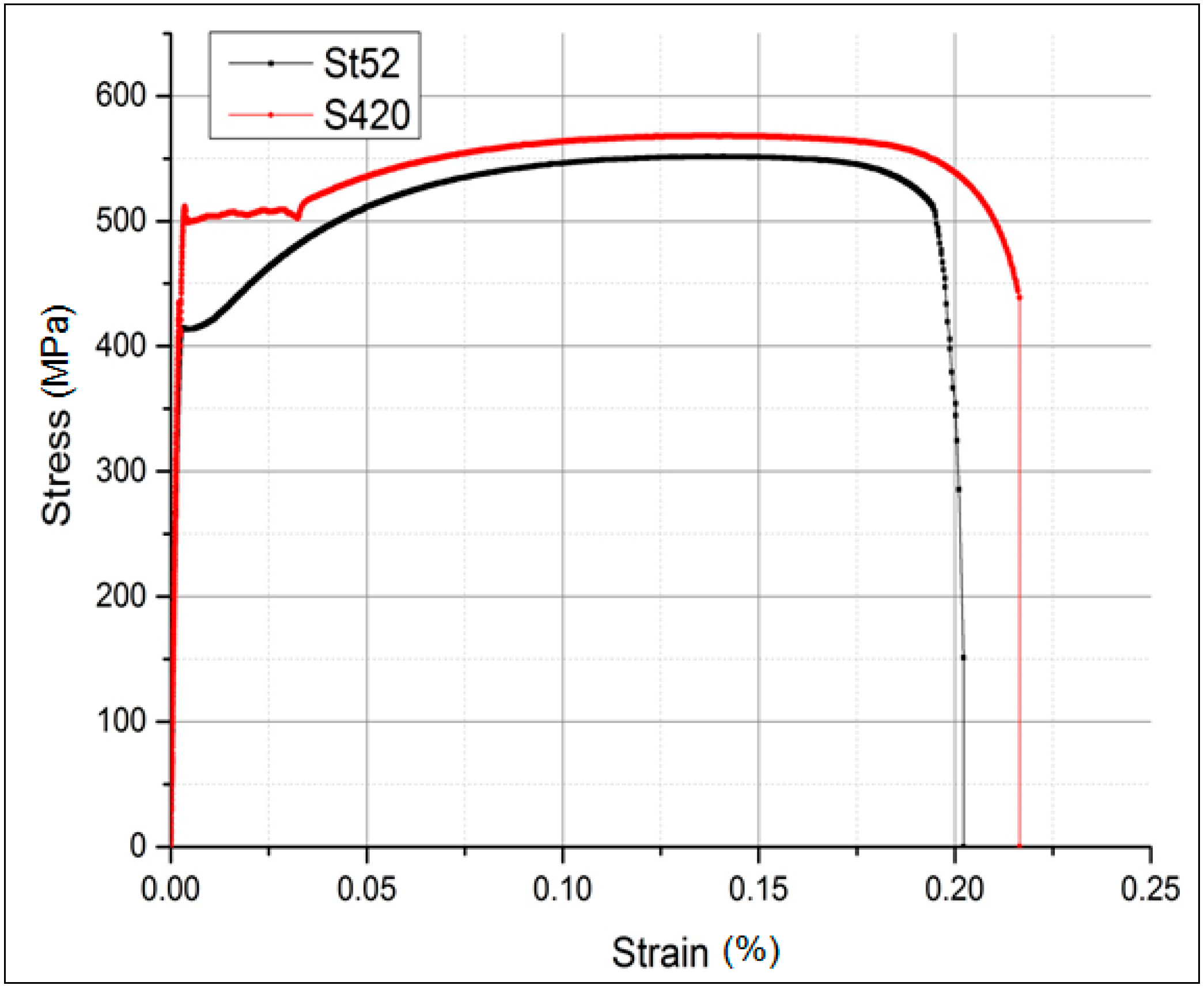
Correct definition of the material properties for the finite element model is critical. During the ECE R14 regulation, high forces acted on the seat structure; thus, the material yield and tensile strength are very important in both the analyses’ and tests’ accomplishments. To estimate the nonlinear behavior of the material, true stress-true strain curves were required. In this study, after the material selection process, which was explained previously, S420MC and St-52 high strength steel were used as the selected candidate materials instead of St-37 conventional steel for the prototype seat frame. To obtain true stress–true strain curves for these materials, tensile tests were performed on sample materials in the Uludag University Laboratory. Their mechanical properties and materials stress-strain curves are shown in
Figure 5. After the determination of the material properties, S420MC high strength steel was observed to be the most suitable material compared to St-52 both tensile and yield strength. S420MC mechanical properties were then defined in HyperMesh.
Figure 5.
Engineering stress-strain curves of candidate materials.
Figure 5.
Engineering stress-strain curves of candidate materials.
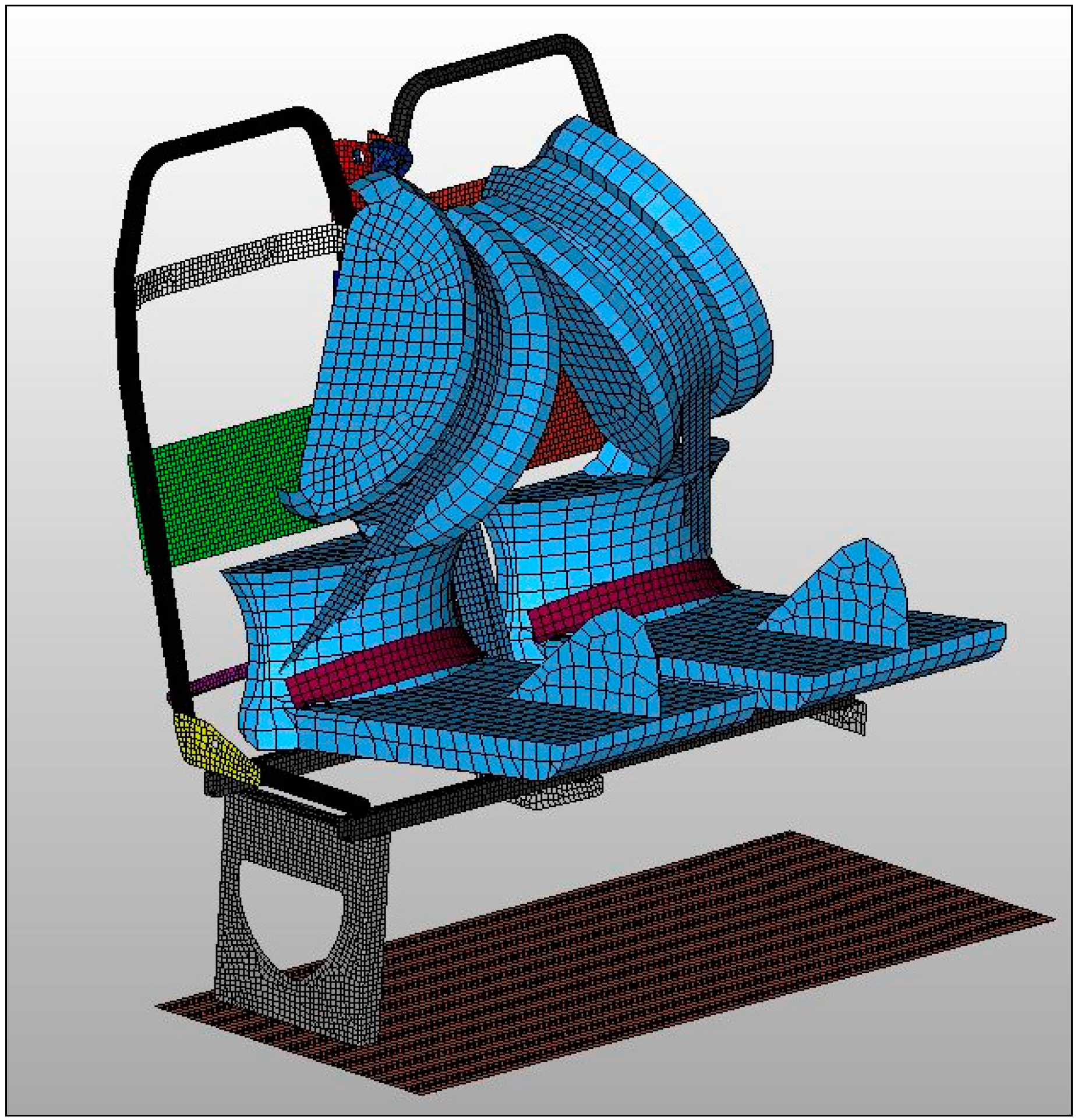
In the present study, the strength of all the anchorage points of the prototype seat was simulated for vehicle impact loads prescribed by body forces in ECE R14. A correct modeling of the kinematics is essential for accurate analysis results. Nonlinear analysis of the ECE R14 test was performed in RADIOSS. The boundary conditions for the finite element analyses of the prototype seat structure were defined according to the regulation of ECE R14 [
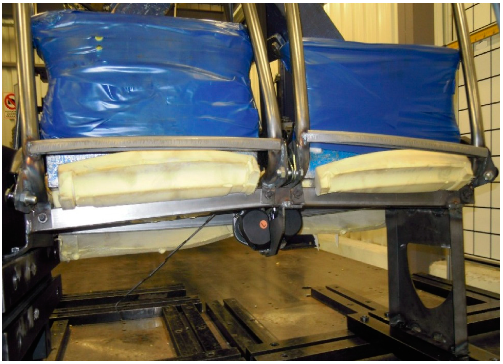
47]. During the test, the fastest way was selected to reach the forces and the structures had to withstand the maximum forces for 0.2 s. The tractive force was applied at an angle of 10° ± 5° above the horizontal in a plane parallel to the plane of the vehicle. Test loads were applied over loading devices (body blocks) (
Figure 6). The forces were determined by the vehicle class (M3 class) and type of seatbelt (three-point). During the analyses, the forces that acted on the body block were determined by the ECE R14 regulation; the shoulder block force was
F1 = 4500
N and the lap block force was
F2 = 6766
N.
Figure 6.
ECE R14 seatbelt test FE model.
Figure 6.
ECE R14 seatbelt test FE model.
To obtain the optimum solution (lightweight and sufficient strength), different profile thicknesses (1, 1.5, 2, 2.5 mm) were used in the FE models. The seat backrest frame pipes consisted of 2 mm thick high strength steel and were maintained constant during the analyses. For all of finite element models, which consisted of different thicknesses of S420MC chassis profiles, ECE R14 tests were conducted in simulations and were evaluated with the help of HyperView. Von Mises stress value of the seat and chassis profiles were investigated.
In the final stage of the study, bench tests were performed. After the examination of the FEA results, a seat design that satisfies performance criteria was determined and the prototype seat manufactured. This prototype was used in validation tests.
One of the most crucial objectives was sufficient strength of the seat. At the end of the test, the seat and anchorages were expected to retain their integrity and the longitudinal displacement could not exceed an allowed scale. One of the important performance indicators of the study was ensured safety tests accordingly ECE R14 regulation. Additionally, weight reduction was the other main indicator, in addition to other technical indicators, including manufacturability and sizing in accordance with the vehicle regulation. The failure modes of this study were materials’ mechanical behaviors and constraints imposed by the regulation. For structural integrity of the lightweight seat, the selected material tensile and yield strength were quite important. During and at the end of the tests, plastic strain of the chassis profiles and displacement of the seat backrest frame must be within the boundary conditions which set by regulations. These were the main failure modes of the study.
3. Results and Discussion
In this paper, a passenger seat for mass transit vehicles is used as a case study for lightweighting under the safety requirements. Using S420MC high strength steel on the chassis and backrest frame, 20% weight reduction was achieved in the entire seat structure. In the chassis frame, high strength steel profiles with 1.5 mm thicknesses were used. The seat pillar also consisted of high strength steel sheet metal welded to the chassis. With the help of the FE analysis, optimum material and profile thicknesses of the seat chassis were determined. Four different profile thicknesses (1, 1.5, 2 and 2.5 mm) were analyzed. The seat backrest frame thickness and material kept constant in the analyses, 2 mm S420MC pipe. The FEA found that, in the chassis frame, high strength steel profiles, which have 1.5 mm thickness, provided structural stability of the seat. After examination of the simulation results, the prototype seats were manufactured and subjected to bench tests. A good correlation was achieved between finite element model and test results. Consequently, new prototype seat was achieved with 20% weight reduction without compromising any safety or comfort criteria.
According to the ECE R14 FEA results, the 1bmm thickness FE analyses revealed that the seat stiffness was not appropriate for the regulation. The maximum von Mises stress occurred in the chassis frame with a value of nearly 620 MPa, which is greater than the material tensile strength. For the chassis, the average von Mises stress was 350 MPa and for the backrest and pillar the von Mises stresses were 320 MPa and 240 MPa, respectively. In addition, plastic strains of the profile and backrest frame displacement exceeded the limits that were determined by the regulations [
47].
The seat chassis structure made 2 and 2.5 mm profile thicknesses met the regulation safety limit. In these models, unlike in the other cases, the maximum von Mises stresses were 543 MPa and 514 MPa, respectively, and occurred where the seat pillars were attached to the vehicle basement. For the 2 mm thickness, the average stresses on the pillar, chassis and backrest frame were 300 MPa, 290 MPa and 285 MPa, respectively. For the 2.5 mm thickness, the average stress values were decreased and for the chassis, pillar and backrest frame, the stresses were 265 MPa, 285 MPa and 280 MPa, respectively. In these cases, the plastic strain and backrest frame displacement met the regulation standards. However, lightweighting of the seat structure with these profile thicknesses was not possible.
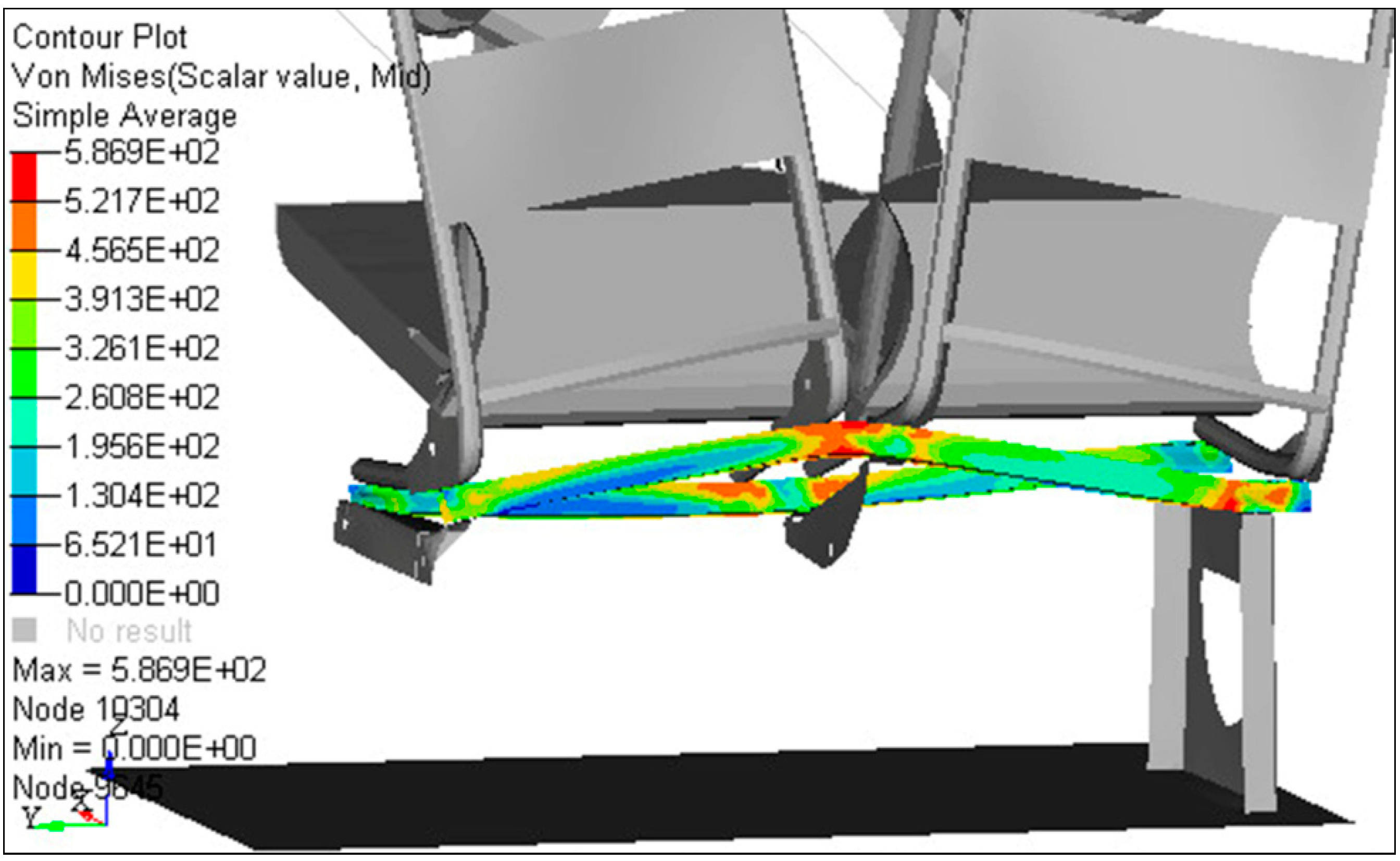
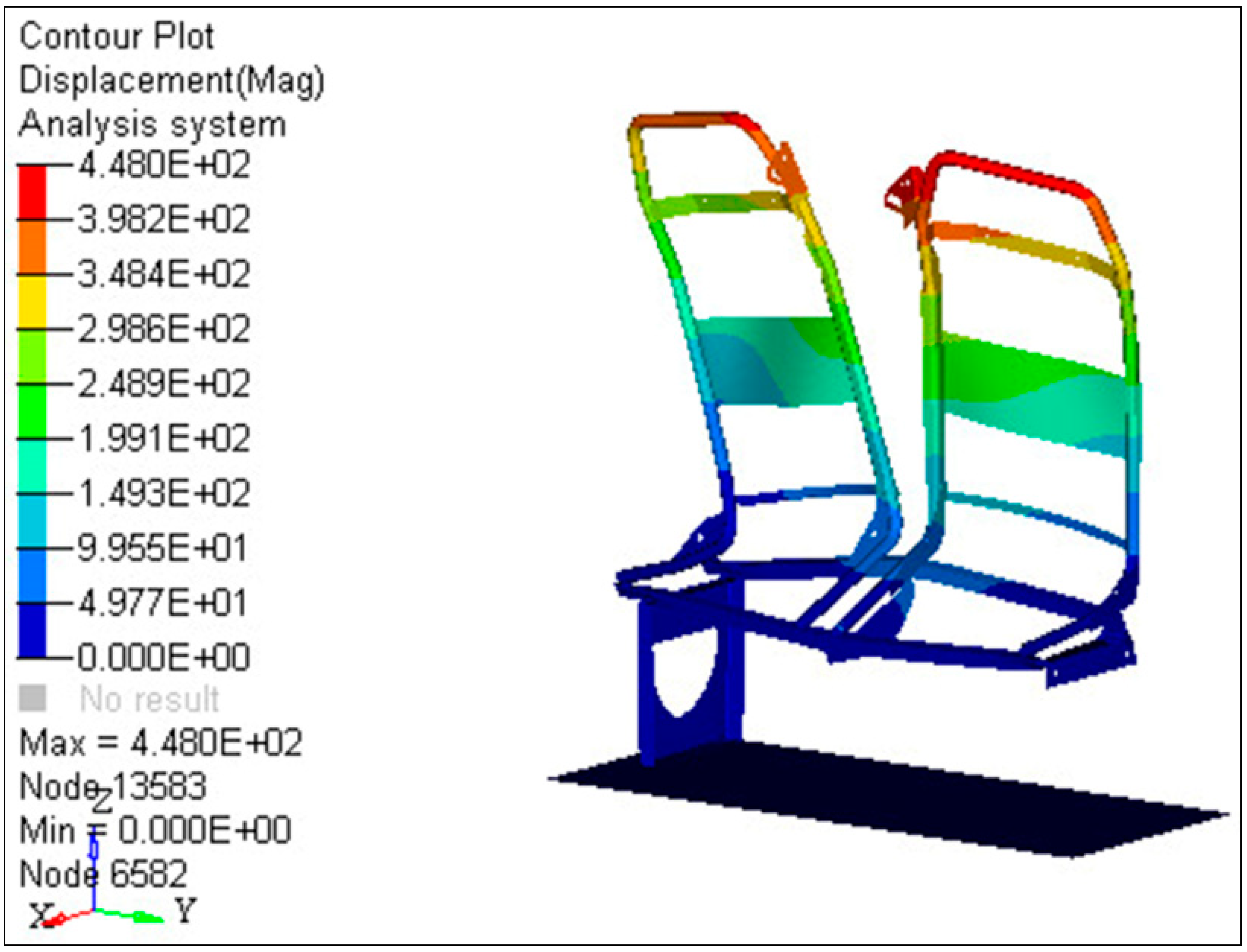
The FE analyses indicate that the 1.5 mm thickness provided the desired safety conditions. Considering the entire seat frame, the maximum von Mises stress was nearly 586 MPa (
Figure 7) and was observed on the middle of the seat chassis rear profile (
Figure 8). At that thickness, the average von Mises stress was 325 MPa for the seat chassis. For the pillar and backrest frame, the average stresses were the same at 300 MPa. These values were appropriate candidate material tensile strength. These results showed that by increasing the stiffness of the seat chassis, pillar and backrest frames, the average stress values were increased.
Figure 7.
Von Mises stress values of the seat (1.5 mm).
Figure 7.
Von Mises stress values of the seat (1.5 mm).
Figure 8.
Von Mises stress values of the chassis profile (1.5 mm).
Figure 8.
Von Mises stress values of the chassis profile (1.5 mm).
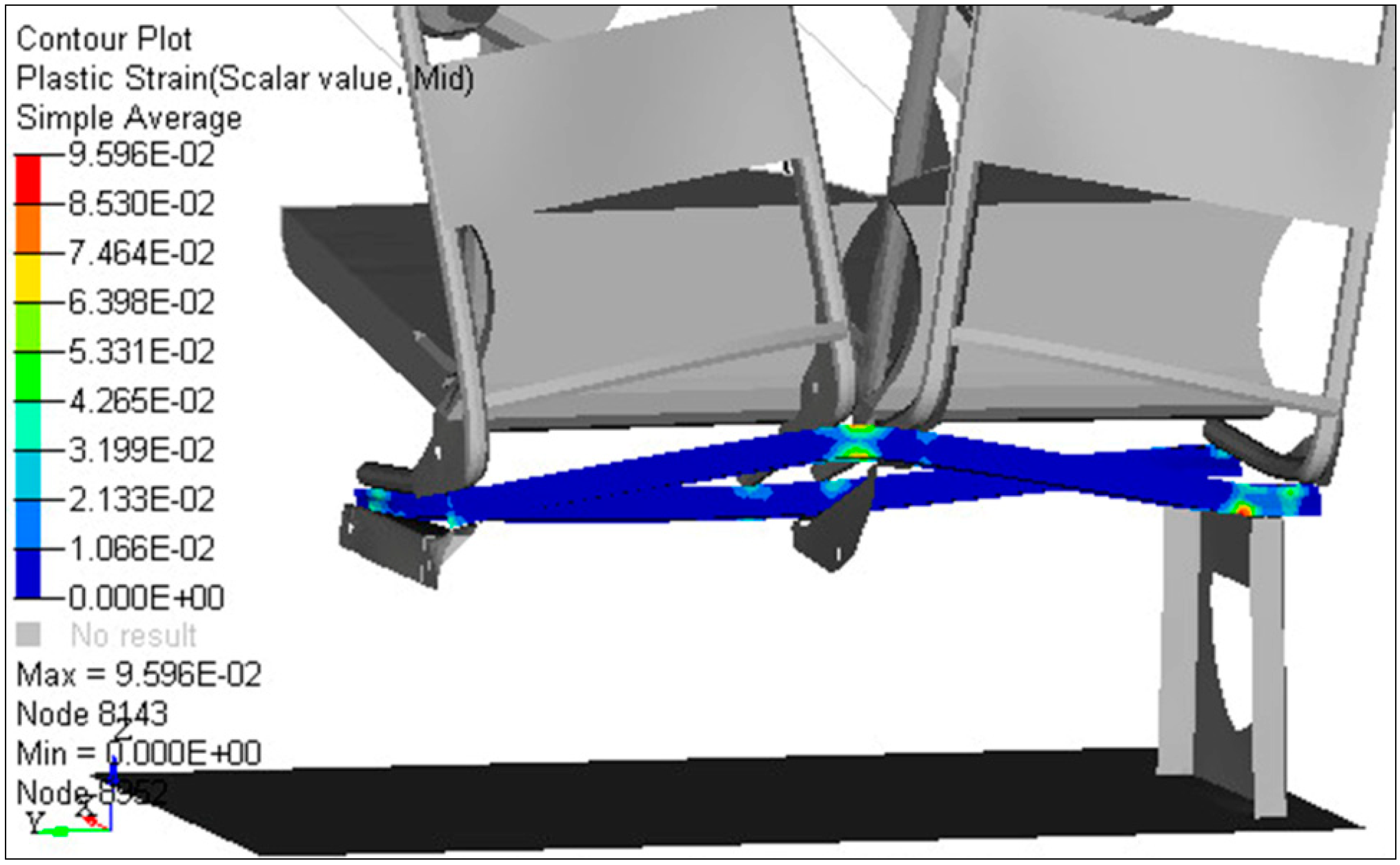
When using 1.5 mm profiles, the plastic strain values were also observed as the limits of the material property. The total elongation of the S420MC steel profile was 16%, and in these analyses, the observed total elongation value was 9.5% (
Figure 9). In addition, the backrest displacement was consistent with the ECE R14 norms for this case (
Figure 10).
Figure 9.
Plastic strain of the seat.
Figure 9.
Plastic strain of the seat.
Figure 10.
Seat backrest displacement.
Figure 10.
Seat backrest displacement.
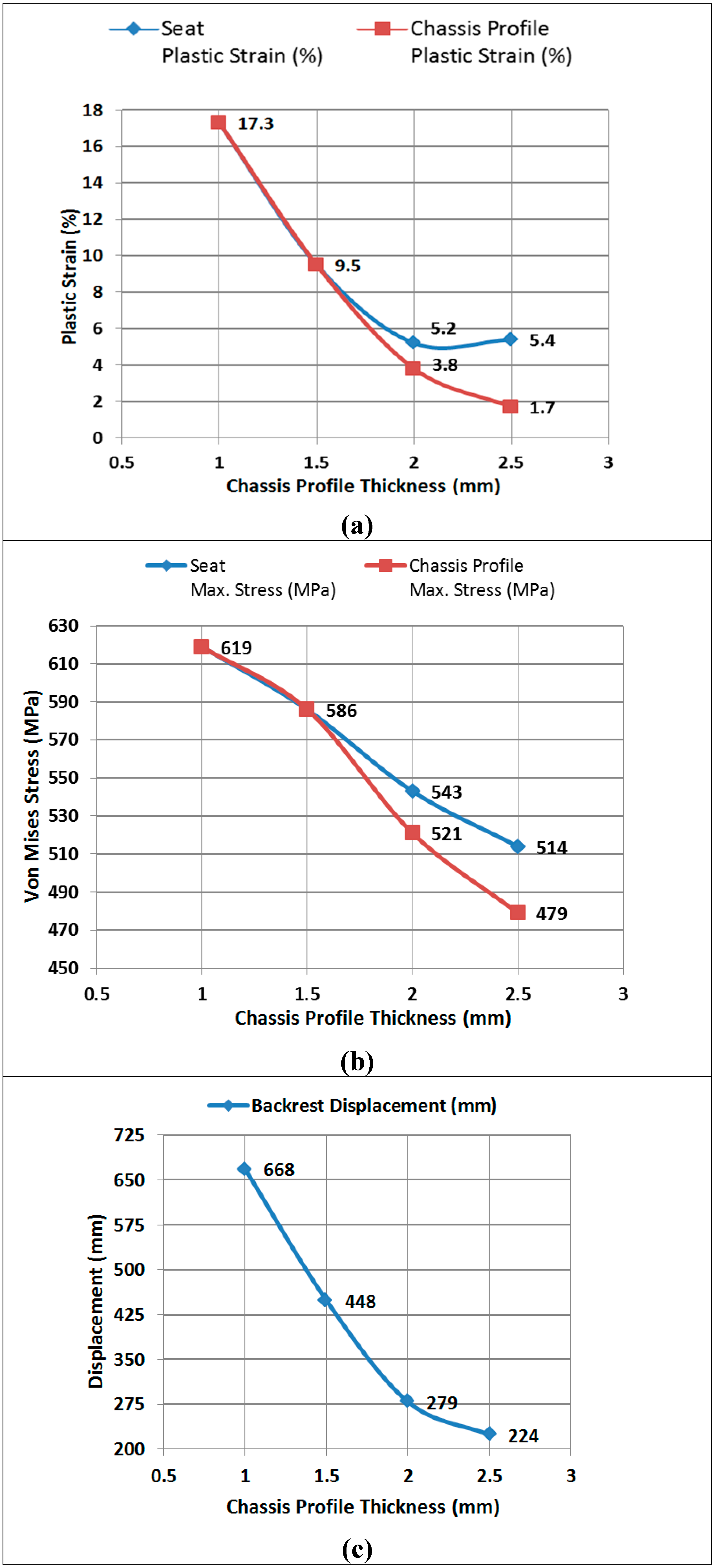
In this study, four different cases were analyzed with the help of RADIOSS and HyperView. For each simulation, the von Mises stress value of the seat, chassis profiles, plastic strain of the chassis profile and displacement of the seat backrest frame were determined. The results are presented in
Figure 11.
Figure 11.
The effect of the chassis profile thicknesses on the FEA. (a) Plastic strain, (b) Von Mises stress and (c) Backrest displacement.
Figure 11.
The effect of the chassis profile thicknesses on the FEA. (a) Plastic strain, (b) Von Mises stress and (c) Backrest displacement.
Because of the increased profile thicknesses, the plastic strain value was decreased on the chassis. For the 1 and 1.5 mm thicknesses, the maximum plastic strain occurred on the chassis as well as on the entire structure. However, for the 2 and 2.5 mm thicknesses, maximum plastic strain occurred in different parts of the seat structure (pillar and chassis welded region) and over this value occurred on the chassis.
With the increase of the thickness of the chassis profiles, the maximum stress value of the seat structure and backrest displacement decreased. The thicknesses of the pipes were reduced using the high strength steel; however, the stiffness of the frame was also reduced. Therefore, the stress values depend on the material properties and thickness. As observed in the FE analyses, the bending sections of the frame, chassis–pillar connection points (welded regions) and seatbelt connection brackets were the most critical parts for the stiffness of the seat.
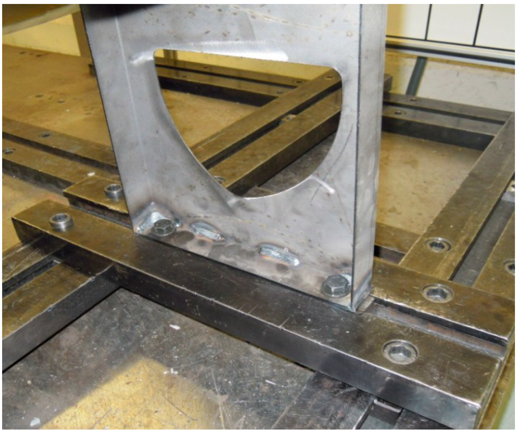
After examination of the simulation results, the prototype seats were manufactured. For verification of the analysis results, prototype lightweight seats were subjected to bench tests defined by the ECE R14 regulations. First, the seat pillar was examined. In the FE analyses, high stress had occurred on the edge of the pillar. As observed in
Figure 12, in the bench test, the same regions were damaged.
Figure 12.
ECE R14 test seat pillar image.
Figure 12.
ECE R14 test seat pillar image.
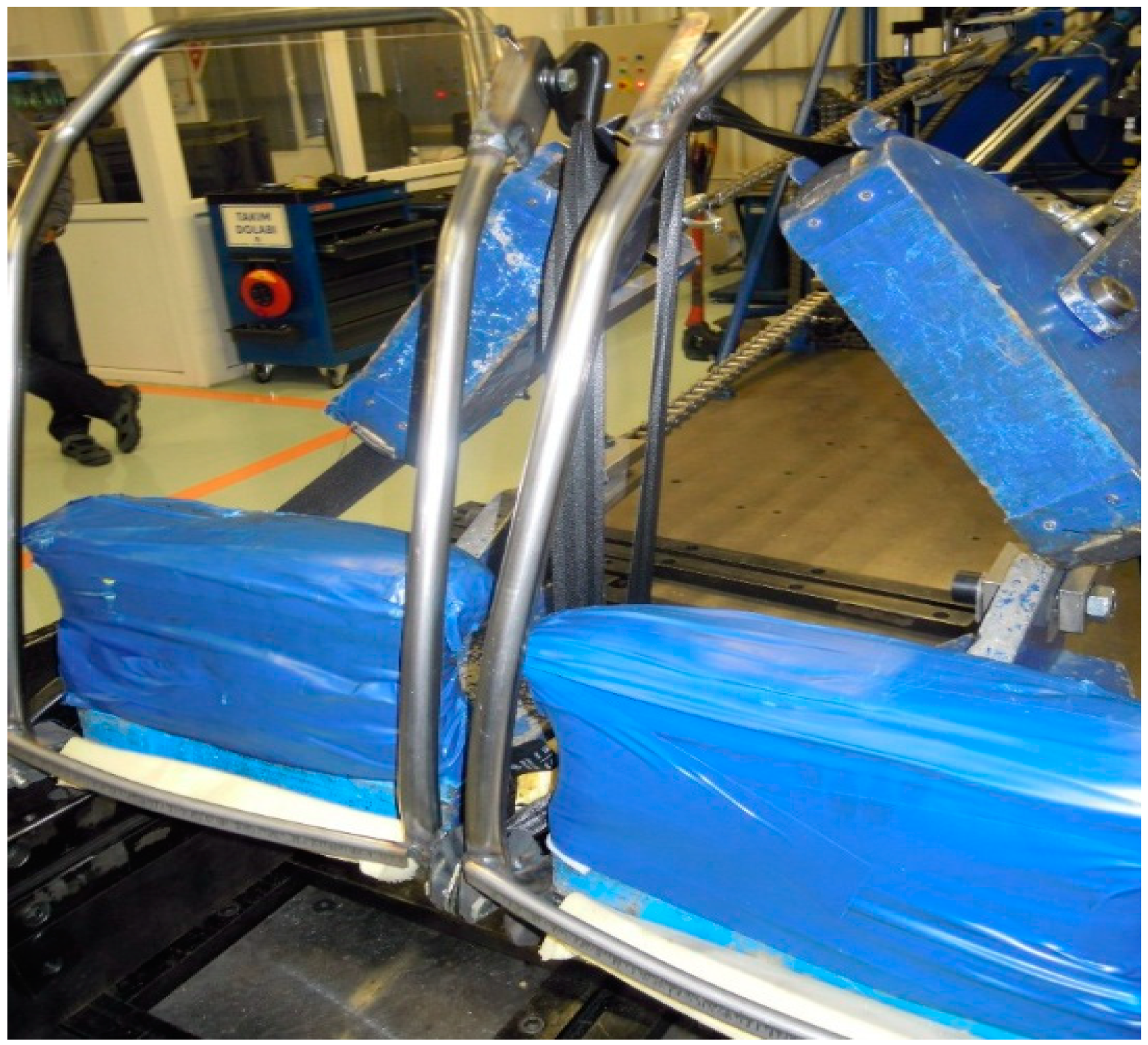
As observed in the analyses, in the ECE R14 test, the most critical part was the chassis rear profile. During the analyses, nearly 520–580 MPa stress occurred for the 1.5 mm thicknesses. In addition, damage emerged in the same region during the bench test (
Figure 13).
Figure 13.
ECE R14 test seat chassis image.
Figure 13.
ECE R14 test seat chassis image.
According to the ECE R14 tests, the seat backrest frame is one of the critical parts. Conventionally, this part is made of St-37 steel pipes, and its thickness is 2.5 mm. The new frame was manufactured using high strength steel with a thickness of 2 mm. In this frame, some weight reduction was achieved but was not significant.
On the backrest frame during the ECE R14 analyses, the maximum stress occurred in the bending areas and chassis contact regions. During the bench test, the damage occurring in the bended and welded region was the same as that observed in the analyses (
Figure 14).
Figure 14.
ECE R14 test seat backrest frame image.
Figure 14.
ECE R14 test seat backrest frame image.
With the engineering design process and material substitution, an overall reduction in weight of 20% was achieved over a reference conventional passenger seat. The new seat’s chassis consisted of 1.5 mm S420MC high strength steel profiles. The seat chassis and pillar were welded together. The backrest frame was also made of S420MC pipes with 2 mm thicknesses. The new passenger seat was subjected to ECE R14 safety tests and successfully passed.
The new lightweight seat can be used in buses and coaches. These transport vehicles have nearly 55 passenger seats depending on the manufacturer, and one of the seats weighs approximately 45 kg. For 20% lightweighting, 495 kg weight reduction is obtained per bus, representing 3% of the bus mass. According to Reference [
61], the specific energy savings for a city bus with a 100 kg weight reduction for 100 km is nearly 0.2 liter. Using the lightweight passenger seats proposed in this study would result in nearly 1 liter of fuel savings for a 100 km distance for city buses.
4. Conclusions
In this study, a lightweight passenger seat for new generation sustainable mass transit vehicles was designed and developed. To select the optimum material, several mechanical tests were performed. Because of the material selection process, the high strength steel was found to be the most proper material in many criteria, e.g., manufacturability, low cost, accessibility and sufficient strength. In the design phase, a 3D CAD model of the seat was created in the presence of many innovative design techniques. For the validation phase in the design stage, a finite element model of the seat was created. To verify the functional performance of the design and to determine the safety for strength, a nonlinear finite element analysis was performed. With the help of the finite element analyses, different profile thicknesses were analyzed in accordance with ECE R14 standards to ensure the lightweight and safety structure. The 1.5 mm thickness was selected for the chassis profile, and the 2 mm thickness was selected for the backrest frame pipes. To verify the analysis results, the seat structure was investigated by conducting bench tests in accordance with ECE safety norms. The new prototype seat achieved 20% weight reduction without compromising any safety or comfort criteria. Additionally, in the new seat design, reduction in the number of parts is provided.
Although some parts, especially the bending areas and seatbelt connection points, were affected by high stresses due to applied forces, these impacts were below the material yield and tensile strength and regulation boundary conditions which are explained in the regulation. The nonlinear analysis demonstrated that local yielding was present; however, the stresses were always considerably less than the ultimate stress of the assigned material. Because of the use of high strength steel, the thicknesses of the pipes and profiles were reduced. The analysis results and bench tests were also compatible. The same parts of the structure were affected by high stress and damage also occurred in these parts in the bench test. The FE analysis and bench tests indicated that the new lightweight passenger seat satisfied the strength and deflection requirements specified by the ECE R14.
In conclusion, this study demonstrates that the high strength steel components in the seat structure are able to meet equivalent safety regulations. This material provided the same stiffness with less thickness and is thus lighter than the conventional structure. It has proven that, the simulation techniques are advantageous for seat safety tests in accordance with ECE. These results will be used for further improvement of the passenger seat anchorage design for safety and lightweighting.
From the viewpoint of sustainable transport, a weight reduction leads to considerable fuel savings for all transport vehicles and especially buses due to high use of phase energy savings. It has been demonstrated that the facilitation of weight reduction could make a significant contribution in reducing the global transport energy consumption.
Due to the high strength-to-weight ratio, high modulus-to-weight ratio, excellent damage tolerance and corrosion resistance and other specific properties, fiber-reinforced composites are alternatives for conventional materials even in structural components. In the following stages of this study, an emphasis will be placed on composites and aluminum. In particular, the seat cushion frame can be manufactured using the pultrusion method, which will permit significant weight reduction with the same rigidity. By utilizing fiber-reinforced composites, aluminum and advanced plastic materials, a hybrid seat structure can be produced. With appropriate production methods, extra design options and cost reductions are also available.


