Article

Stationary Charging Station Design for Sustainable Urban Rail Systems: A Case Study at Zhuzhou Electric Locomotive Co., China

1
School of Information Science and Engineering, Central South University, 22 South Shaoshan Road, Changsha 410000, China
2
Institute of Network Communication and Control for Transportation System, Central South University, 22 South Shaoshan Road, Changsha 410000, China
*
Author to whom correspondence should be addressed.
Sustainability 2015, 7(1), 465-481; https://doi.org/10.3390/su7010465
Submission received: 7 November 2014 / Accepted: 29 December 2014 / Published: 5 January 2015
(This article belongs to the Special Issue Sustainability in Electrical Engineering)

Abstract

:
In 2014, more than 43 cities in China were racing to construct their urban rail systems (including metro and light rail systems), recognizing that an urban rail system will be a good solution to the tough problems that they are faced with, including traffic congestion and PM2.5 air pollution. On 22 August 2012, the first electric double-layer capacitor (EDLC) energy storage-type rail vehicle in the world was unveiled at Zhuzhou Electric Locomotive Co., China. The EDLC rail system has been considered a promising sustainable urban rail system, which is expected to further improve the energy efficiency and to reduce environmental pollution. The first commercial EDLC tram produced by Zhuzhou Electric Locomotive Co. has been applied at Guangzhou Metro Corp. recently. From the view point of scientific research, the system design and energy management of EDLC rail systems have been extensively studied in the literature, while the stationary charging station design for the EDLC energy storage-type urban rail vehicles has been rarely reported. Thus, the aim of this paper is to report a stationary charging station that has been successfully applied in the EDLC rail system produced by Zhuzhou Electric Locomotive Co., China.

Graphical Abstract

1. Introduction

Having benefited from rapid economic development for over 30 years, China finds itself coping with the relatively new phenomena of rapid urbanization [1]. The urbanization rate in China grew from 20% in 1980 to 46.7% in 2010, and the urban population increased by almost 350 million over the last 30 years [2]. To accommodate the rapidly-increasing population, the urbanized area has expanded to the outlying rural areas, which lengthens travel distance and encourages the desire to travel by car. The registered numbers of automobiles in China increased from 12.8 million in 1990 to 140 million in 2014 [3]. This rapid motorization led to serious traffic congestion and PM2.5 air pollution in China, especially in metropolises and some mid-sized cities. Figure 1 shows the traffic congestion and PM2.5 air pollution in Beijing.
Figure 1. The traffic congestion and PM2.5 air pollution in Beijing. (a) Traffic congestion; (a) PM2.5 air pollution.
Sustainability 07 00465 g001
The Chinese society has gradually realized that we cannot sustain endless motorization. Instead, sustainable transport strategies have to be adopted to avoid being trapped in a car-oriented urban development. The urban rail system (including the metro and light rail system) has been considered a good choice. In 2014, there were more than 35 cities in China extending new subway lines or opening the first subway lines. Moreover, there are eight cities operating or constructing their own light rail systems [4].
Viewing the practical urban progress in the world, the urban rail system becomes a major urban transportation tool in developed countries and regions for its advantages, such as mass transit capacity, fast speed, safety and reliability, punctuation and comfort [5]. Nonetheless, in order to retain its environmental advantages over other transportation modes in urban areas, significant improvements in the energy efficiency of urban rail systems have to be further achieved [6]. For instance, in traditional urban rail systems, power is supplied to rail vehicles with a continuous conductor running along the rail that usually takes one of the following two forms. The first is an overhead line or catenary wire suspended from poles or towers along the rail. The other is a third rail mounted at the track level and contacted by a sliding “pickup shoe” [7]. However, both the overhead wire and third-rail systems suffer from the same disadvantages, including high capital costs, line voltage drops, undesired power peaks, electromagnetic pollution and damage to the landscape along the rail. Moreover, since numerous and frequent stops are a significant characteristic of urban rail, reuse of braking energy offers a great potential to improve the energy efficiency. Thus, it is of practical interest to develop an urban rail system that is more energy efficient and environment friendly.
Recent studies have indicated that an energy storage system (ESS) will be helpful in improving the energy efficiency of conventional urban rail systems; see [6,8,9,10,11,12,13,14,15,16,17]. The ESS stores energy using storage devices with good power density and a high number of cycles, such as an electric double-layer capacitor (EDLC), flywheels and superconducting magnetic energy storage (SMES) [11]. The ESS can be either installed onboard the vehicle [6,10,16,17] or installed at the substation level or along the track [8,9,10,11,12,13,14,15]. In the former case, the ESS is called the onboard ESS, which is used to recover the braking energy and to smooth the electric power peak of hybrid vehicles. In the latter case, the ESS is called the stationary ESS, which is used to recover the braking energy of conventional vehicles and to support the line voltage at weak points [8]. However, in these studies, neither the stationary ESS nor onboard ESS work as the main power source. The rail vehicles are still mainly powered by the overhead line or third track, while the ESS only works as a supplementary power source to improve the power network performance. This fact implies that the drawbacks of the traditional overhead line and third track systems still exist, even though some of them can be alleviated by the ESS.
On 22 August 2012, Zhuzhou Electric Locomotive Co. unveiled the first rail vehicle in the world that is only powered by onboard EDLC-based ESS. Different from existing urban rail systems, the unveiled urban rail vehicle does not call for the overhead wire or the third rail to supply energy. Instead, the vehicle is totally steered by the onboard EDLC stacks. Thus the capital costs of power network construction will be saved, and then, the line voltage drop and undesired power peaks can also be omitted. Moreover, without the construction of power supply networks, the electrochemical pollution of the power network can be avoided and the landscape along the rail will not be influenced; thus, the urban rail system will be very environmentally friendly. The EDLC energy storage-type urban rail system has been considered a promising sustainable urban rail system in China. The first commercial EDLC tram is to enter passenger service in Guangzhou Metro Corp. in late December, 2014.
Since the urban rail vehicle is 100% powered by the onboard EDLC-based ESS, it is very important for the vehicle manufacturer to size the onboard ESS appropriately by fully considering the travel distance between stations, transit capacity and the maximum amount of braking energy. This is an interesting topic, but out of the scope of this paper. In this paper, we will focus on the stationary charging station design for the EDLC energy storage-type urban rail vehicles. The charging stations are placed at the subway or transit stations to power the vehicle when it parks at the platform for passenger boarding. The charging station will be connected to the vehicle directly without any power supply networks. The charging takes about 30 s and can power the train for 4 km.
It is worth noting that the stationary charging station reported in this paper and the stationary ESS mentioned above are different concepts. The stationary ESSs are typically designed for traditional power supply networks with conventional vehicles and applied at weak points of the contact lines to support the line voltage. The two key challenges of stationary ESSs are the optimal sizing and optimal positioning. In the literature [8,9,10,11,12,13,14,15], several ESS sizing and positioning methods have been proposed for EDLC-based stationary ESSs. While the stationary charging station design in this paper is quite a different problem. The stationary charging station does not consist of EDLCs and does not store energy itself. It is used to charge the EDLC energy storage-type urban rail vehicle and not used to improve the power network performance. The stationary charging station converts the energy from the city electric grid to the EDLC energy storage-type urban rail vehicle directly without any power supply networks.
The ground charging system for EDLC rail vehicles at the platform is shown in Figure 2. The stationary charging station is connected to the pantograph installed at the edge of the platform at the design time. When the urban vehicle parks at the platform for passenger boarding, the pantograph will be outspread and connected to the underfloor current collector of the vehicle. Then, the stationary charging station will charge the onboard EDLC stacks. Upon the completion of the charging, the pantograph will be disconnected from the vehicle, and the vehicle will move to the next transit station. The ground charging system consists of three components: stationary charging station, pantograph and urban rail vehicle. From the view point of scientific research, the system design and energy management of urban rail vehicles have been extensively discussed in the literature [18,19,20,21], while the stationary charging station design for sustainable urban rail systems has been rarely reported. Thus, the aim of this paper is to report a stationary charging station that has been successfully applied in the EDLC energy storage-type urban rail system produced by Zhuzhou Electric Locomotive Co., China.
Figure 2. The ground charging system for EDLC rail vehicles at the platform.
Sustainability 07 00465 g002
In most cases, the charging time for the onboard EDLC stacks is limited. For instance, the urban rail vehicle typically parks at the platform for only a few seconds for passenger boarding. The charging station should be designed to supply large enough output power to shorten the charging time. One common way to solve this problem is to connect chargers in parallel [22]. In fact, it has been shown that compared with a single “large charger”, the parallel connection of “small chargers” has many advantages, including high reliability, smaller ripples and higher system bandwidth [23]. However, parallel connection of chargers will typically lead to a current imbalance between chargers, which may lead to damage to the charging station. Therefore, current balancing is a basic requirement in the charging station design.
There are several current balancing methods that have been proposed in the literature, such as the droop control method [24,25,26] and the master-slave method [27,28]. In the droop control method, the current balancing is achieved by regulating the output impedance of each charger without any communications between them. A peculiar aspect of this method is that it only has a proportional controller for current and voltage, lacking any form of integral control. Control of a distributed system without communication can only be achieved at the price of permitting a certain error; thus the droop control method is rarely applied in large power applications. The basic idea of the master-slave method is to choose one charger as the master module and then to design controllers to ensure that all other chargers follow the reference current of the master. The connections between the master and the slave can either be a physical connection or wireless communication [27]. Since the master-slave method is a centralized current balancing method, the complexity of the algorithm will increase dramatically when the number of parallel chargers increases.
In this paper, we propose a simple, but efficient, current balancing method, namely the cooperative proportional-integral (PI) current balancing method. In the proposed method, there are 2n 1 PI algorithms for n parallel chargers. The n local PI algorithms are responsible for achieving the output current target at the final state of each charger. The other n 1 algorithms are called cooperative algorithms, which are responsible for the current balancing during the output current convergence between neighboring chargers. The proposed method is very easy in its hardware implementation, and we provide experiment results to illustrate the effectiveness of the proposed method.
The remainder of this paper is organized as follows. In Section 2, the schematic, control strategy and physical implementation of the stationary charging station are introduced. In Section 3, experimental results are provided to show the effectiveness of the design. We conclude the paper in Section 4.

2. Charging Station Design
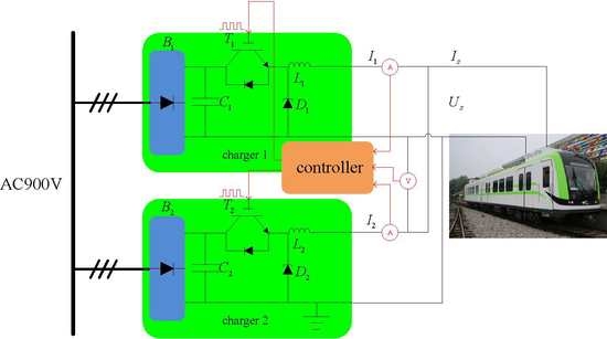
The stationary charging station design for the EDLC energy storage-type urban rail systems is introduced in this section. The schematic of the charging station is introduced first. Then, we propose a cooperative proportional-integral (PI) current balancing control strategy to suppress the current imbalance between chargers. The physical implementation of the charging station is presented at the end of this section.

2.1. Schematic

The schematic of the stationary charging station is shown in Figure 3. The charging station is comprised of an embedded controller and two parallel chargers. The embedded controller monitors and regulates the output current of the two chargers. Each charger consists of a three-phase bridge rectifier Bi (i = 1, 2) and a buck converter. The three-phase bridge rectifier converts the input power from alternative to direct form. The buck converter consists of an insulated gate bipolar translator (IGBT) Ti, a free-wheeling diode Di, a filtering capacitor Ci and an inductor Li. The output current of charger i is denoted as Ii; then, the total output current of the charging system is denoted as Is = I1 + I2.
Figure 3. The schematic of the stationary charging station.
Sustainability 07 00465 g003
Denote Cs as the capacitance of the EDLC stack; then, we can derive the averaging model of the whole system. When IGBT Ti is on, the state equation of charger i is denoted as:
d I i d t = U B i L i = U s L i , d U s d t = I s C s
where UBi is the output voltage of rectifier Bi, IBi is the output current of rectifier Bi and Us is the terminal voltage of the super-capacitor stack.
When IGBT Ti is off, the state equation of charger i is given by:
d I i d t = U s L i , d U s d t = I s C s .
Then, the unified system dynamics of charger i can be represented by:
d I i d t = U B i L i τ i U s L i , d U s d t = I s C s ,
where τi is the duty cycle of PWMsignals injected to IGBT Ti.
With the charging station model (2), a charging controller can be designed to regulate the output voltage and current of the charging station, and then handle the current imbalance between chargers.

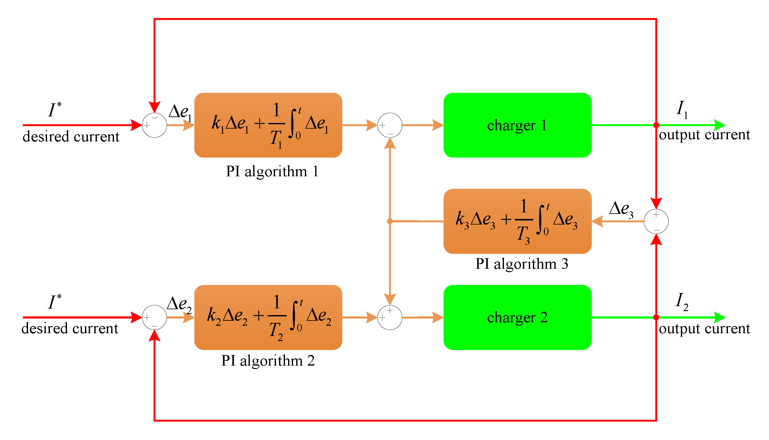
2.2. Control Strategy

In this section, a cooperative current balancing control strategy is designed to handle the charging problem of parallel chargers. As shown in Figure 4, the cooperative current balancing control strategy of comprised of three PI algorithms. The first and second PI algorithms are local controllers, which are designed to ensure the output currents I1 and I2 of two chargers converge to the desired current I at the final state. The third PI algorithm is the cooperative controller, which guarantees the current balance between two chargers during convergence.
Figure 4. The cooperative current balancing control strategy.
Sustainability 07 00465 g004
Then, the control input τ1 for Charger 1 can be written as:
τ 1 = k 1 Δ e 1 + 1 T 1 0 t Δ e 1 k 3 Δ e 3 1 T 3 0 t Δ e 3 .
Similarly, the control input τ2 for Charger 2 is denoted as:
τ 2 = k 2 Δ e 2 + 1 T 2 0 t Δ e 2 + k 3 Δ e 3 + 1 T 3 0 t Δ e 3 .
Then, by combing Equations (3)–(5), the closed-loop system for the charging station can be described as follows:
d I i d t = U B i L i τ i U s L i , d U s d t = I s C s , τ i = k i Δ e i + 1 T i 0 t Δ e i + ( 1 ) i [ k 3 Δ e 3 + 1 T 3 0 t Δ e 3 ] ,    i =1,2 .
Based on the operation requirement of the super-capacitor urban rail vehicle, the output current of the charging station is required to increase to the desired value Is in a limited time. Then, the vehicle is charged with constant current Is, until the output voltage reaches the setpoint Us. Denote the desired current of each charger as I, where I = 1 2 I s . Then, the control objective is to design an embedded charging controller to regulate the control input τi for charger i until the output currents I1, I2 converge to the desired current I and the output voltage Us converges to the desired voltage Us.

2.3. Implementation

In this subsection, we will introduce the physical implementation of the charging station. The charging control procedure, the control board design and the hardware implementation of the charging station will be presented.
We should specify the adopted charging method before the charging control procedure is designed. As a rapid charging method, constant current charging has been widely used in engineering applications. The onboard EDLC stacks will be charged by the stationary charging station using the constant current method. The desired output current profile of the charging station is shown in Figure 5.
Figure 5. The desired output current profile of the charging station.
Sustainability 07 00465 g005
As shown in Figure 5, there are three charging stages, which are introduced as follows.
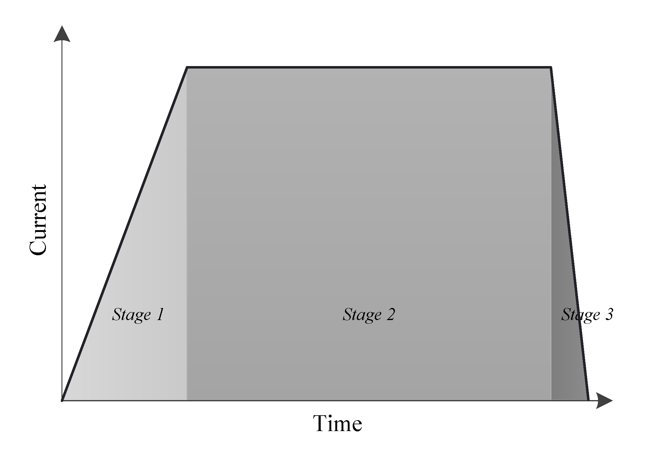
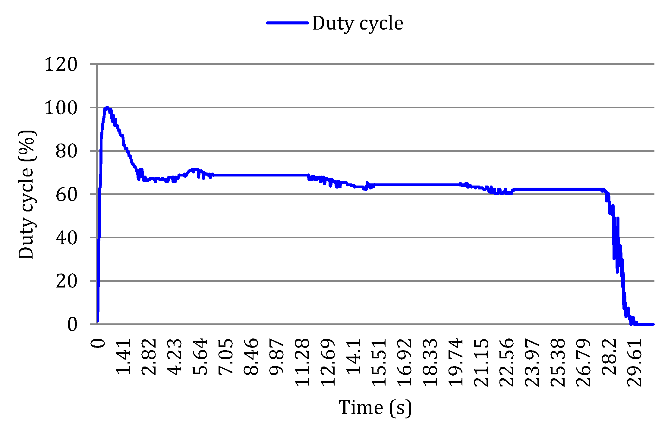
  • Stage 1: The output current of the stationary charging station increases to the desired value Is*rapidly.
  • Stage 2: The output current of the stationary charging station keeps constant at Is. The onboard EDLC stacks are charged with constant current Is.
  • Stage 3: The output current of the stationary charging station decreases to zero rapidly. The charging is complete, and the stationary charging station can be disconnected from the vehicle.
The charging control procedure can be represented as a flow chart, which is shown in Algorithm 1. The basic idea is that the current and voltage sensors measure output currents and output voltage of the parallel chargers. If the charging current Ii is less than the desired current I, update the control input τi until Ii reaches I. Then, the controller judges if the output voltage Us reaches the desired voltage Us. If no, update the control input τi until the output voltage Us increases to the desired value Us; if yes, set the control input τi = 0; then, the charging current will decrease to zero. This means that the charging is complete and the charging station can be disconnected from the vehicle.
The proposed charging control procedure can be easily programmed in microcontrollers. With the proposed control procedure, now we need to design a control board that monitors and controls the charging station. The control board of the charging station is shown in Figure 6. There are mainly six modules in the control board, which are introduced as follows.
Algorithm 1 The flow chart of charging control procedure.
1:Initialization;
2:Measure the output current Ii(k) and output voltage Us(k);
3:if Ii(k) < I then
4: Update the control input τi(k) by
τ i ( k ) = k i Δ e i ( k ) + 1 T i 0 t Δ e i ( k ) + ( 1 ) i [ k 3 Δ e 3 ( k ) + 1 T 3 0 t Δ e 3 ( k ) ] ;
           % cooperative PI charging control algorithm
 k = k + 1;
 goto Step 2;
5:else
6: if Us(k) < Us then
7:  goto Step 4;
8:  else
9:  Set τi = 0; % the charging is complete;
10:  end if
11: end if
12:End.
Figure 6. The control board of the stationary charging station.
Sustainability 07 00465 g006
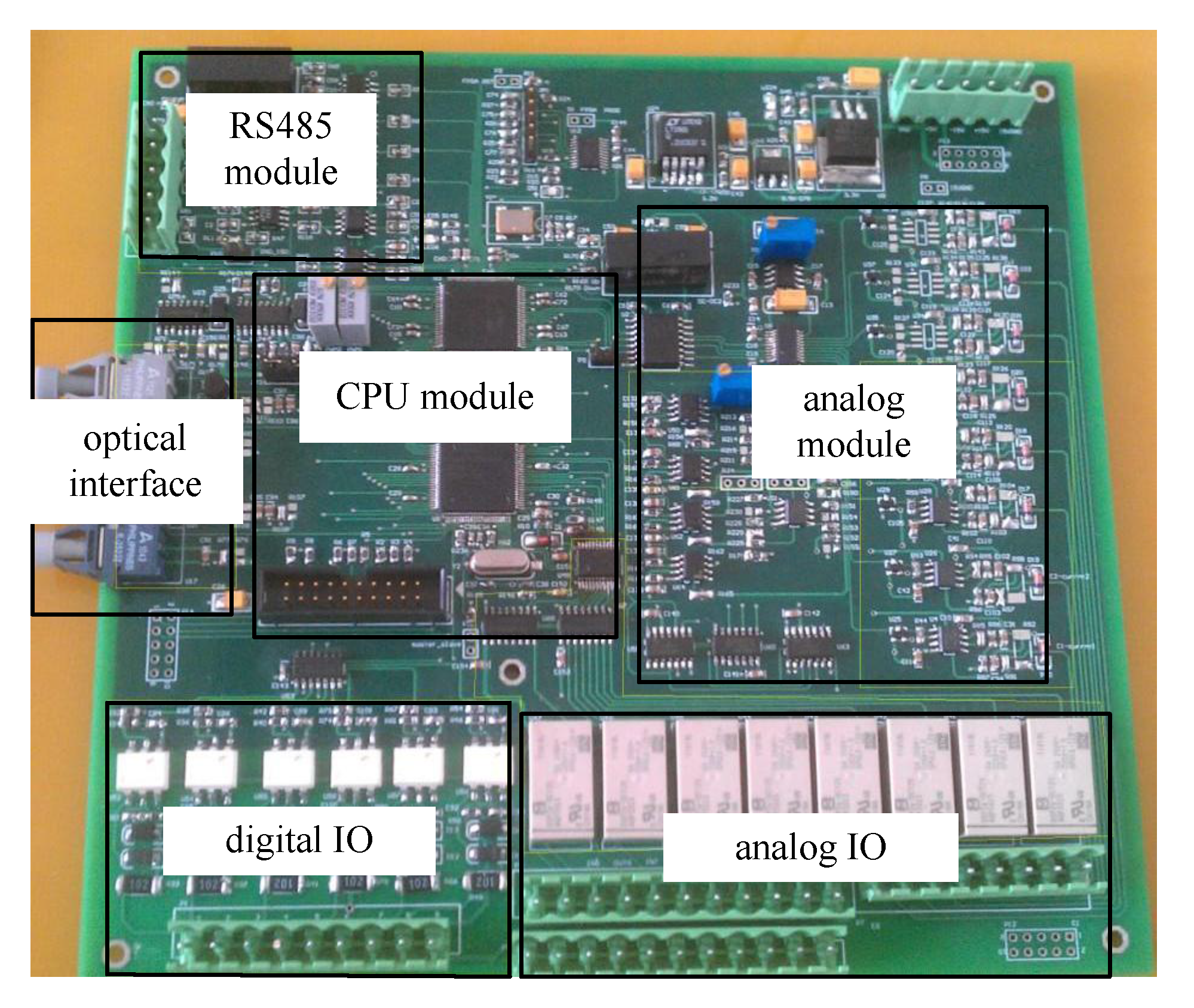
  • Digital IO: The digital IO is used to transmit commands from the control panel to the control board. The command signals include starting up, shutdown and switching modes.
  • Analog IO: The analog IO is used to transmit measurements from sensors to the control board.
  • Analog module: The analog module is used to preprocess the measurements from sensors before the measurements are stored and processed in the CPU.
  • CPU module: The CPU module consists of two microcontrollers: FPGA XC3S50 and ARMLPC1766. XC3S50 is used to store and process data (including filtering, sequencing, etc.), and LPC1766 is used to run the charging control algorithm and to produce PWM control signals.
  • RS485 module: The RS485 module is used to communicate with the personal computer (PC). All transient data in XC3S50 can be transmitted to the PC. Thus, it provides the flexibility of plotting the transient data in drawing software in teh PC.
  • Optical interface: The optical interface is used to transmit PWM control signals from the control board to the IGBT driver. The advantage of the optical interface is that it can effectively shield the PWM control signals from electromagnetic interference.
The front panel and internal structure of the charging station are shown in Figure 7. The input of the charging station is AC900V. The stationary charging station is designed to supply a 900 A current and DC750Vvoltage to charge onboard EDLC stacks when the urban rail vehicle parks at the platform. When the current increases to 900 A and the voltage reaches 750 V, the charging is complete. Then, the output current decreases to zero rapidly, and the charging station can be disconnected from the urban rail vehicle.
Figure 7. The front panel and internal structure of the stationary charging station. (a) Front panel; (b) internal structure.
Sustainability 07 00465 g007
The size of the charging station is 3.5 m × 3.5 m × 2 m. The stationary charging station can be placed at the subway or transit stations conveniently with such a small size. The appearance of the charging station is shown in Figure 8.
Figure 8. The appearance of the stationary charging station.
Sustainability 07 00465 g008

3. Experimental Results

In this section, experimental results from the stationary charging station are presented to illustrate the effectiveness of the design. The charging performance metrics, including output current and voltage, current imbalance, and duty cycle of PWM waves, are transmitted from the RS485 module of the control board and plotted in Excel in the PC. The real-time waves, including PWM control signal and switching voltage of IGBT, are displayed in the oscilloscope.
The output current and voltage of the stationary charging station are shown in Figure 9. It is shown that the output current increases to 900 A within 3 s. Then, the urban rail vehicle is charged with a constant current of 900 A until the charging voltage increases to the desired voltage, 750 V. This means that the vehicle is fully charged. Then, the charging current decreases to zero rapidly, and the charging station can be disconnected from the urban rail vehicle.
Figure 9. The output current and voltage of the charging station.
Sustainability 07 00465 g009
Figure 10 shows the amplified current and voltage curves at Region A and Region B of Figure 9. It further shows that the output current increases to 900 A within 3 s and that the output voltage converges to 750 V within 30 s.
The current imbalance between chargers during the charging convergence is shown in Figure 11. It is shown that the current imbalance is always smaller than 1.5 A. Moreover, the current imbalance is suppressed to zero, as long as the current control is stable.
The duty cycle of PWM control signals from a charging controller is shown in Figure 12. When the charging is complete, the duty cycle (control input) is set to zero; then, the charging current decreases to zero rapidly, and the charging is complete.
Figure 10. The amplified current and voltage curves at Region A and Region B. (a) The current curve at Region A; (b) the voltage curve at Region B.
Sustainability 07 00465 g010
Figure 11. The current imbalance between two parallel chargers.
Sustainability 07 00465 g011
Figure 12. The duty cycle of PWMcontrol signals.
Sustainability 07 00465 g012
The real-time waveforms of PWM control signal and the switching voltage of an IGBT are shown in Figure 13. We can see that when there are control signals (the voltage of the PWM signal is 3.6 V), the terminal voltage of the IGBT is 0 V, which implies that the IGBT is on; when there are no control signals (the voltage of the PWM signal is 0 V), the terminal voltage of the IGBT is 900 V, which means that the IGBT is off. Figure 9 and Figure 12 indicate that the output current and voltage are regulated by the duty cycles of the PWM control signals from the charging controller, while Figure 13 further explains that the charging controller regulates the output signals by controlling the IGBTs.
Figure 13. The PWM signal (green line) and switching voltage of an insulated gate bipolar translator (IGBT) (pink line). (a) t = 1s; (b) t = 15s; (c) t = 29s.
Sustainability 07 00465 g013

4. Concluding Remarks

Due to the rapid urbanization and motorization in China, there is a huge investment in the development of urban rail infrastructure and services. In 2014, there are more than 35 cities in China extending new subway lines or opening their first subway lines. Moreover, there are eight cities operating or constructing their own light rail systems. Behind this significant expansion of infrastructure, however, there are also some concerns about whether these investments are sustainable. These concerns relate to funding mechanisms and policy effects, as well as the rail system’s efficiency and environmental protection.
The technical progress has promoted the development of urban rail systems. The application of energy storage systems (ESSs) has proven an efficient way to improve the energy efficiency and network performance of conventional urban rail systems. However, in existing urban rail systems equipped with ESS, the ESS only works as a supplementary power source, and the urban rail vehicles are still mainly powered by the power supply network. This means that these ESS-based urban rail systems still suffer from the same disadvantages as conventional urban rail systems, such as the capital cost of power network construction, electrochemical pollution and damage to the landscape along the rail.
On 22 August 2012, the world’s first energy storage urban rail vehicle was unveiled at Zhuzhou Electric Locomotive Co., China. Different from existing urban rail vehicles, it is 100% powered by the onboard EDLC-based ESS and does not need the power supply networks. The vehicle is charged by the stationary charging station directly when it parks at the platform for passenger boarding.
The EDLC energy storage-type urban rail system has been considered a sustainable urban rail system in metropolises and mid-sized cities. Without the construction of power supply networks, the urban rail system can be integrated into the city in a real sense. The first commercial EDLC energy storage type tram will enter passenger service at Guangzhou Metro Corp. in late December, 2014. As an energy-efficient and environmentally-friendly urban rail system, the EDLC energy storage-type urban rail system has a bright market prospect.
In this paper, we design a stationary charging station to charge the EDLC energy storage-type urban rail vehicles. A cooperative PI charging control strategy is proposed to solve the current imbalance problem in stationary charging station design. The detailed software and hardware implementation of the stationary charging station design are presented. Experimental results verify the effectiveness of the design.
The stationary charging station is designed with the principles of low cost and high reliability. Based on these principles, the charging station is designed with two small chargers connected in parallel, rather than a single charger with a high output power. The circuit topology of each charger is quite simplified, with only a rectifier and a buck converter. The charging control algorithm is simple, but effective. The concise hardware and software setups make the charging station easy to operate and maintain. However, since the charging station is required to supply a very large amount of power in a limited time, the electric grid typically suffers from high pressure in terms of the maximum power peak. A reasonable idea to solve this problem is to install a fast ESS in the stationary charging station to help improve the electric grid performance. This refers to the concept of “hybrid” stationary charging station design. The idea of a hybrid stationary charging station seems novel and deserves further investigation in future work.

Supplementary Materials

Supplementary materials can be accessed at: https://www.mdpi.com/2071-1050/7/1/0465/s1.

Acknowledgments

The authors would like to thank the anonymous reviewers for their constructive comments. This work is partially supported by the National Nature Science Foundation (Grant Nos. 61202342, 61379111, 61402538, 61403424) and the Hunan Provincial Innovation Foundation For Postgraduates.

Author Contributions

The cooperative PI charging method was proposed by Jun Peng and Zhiwu Huang. The experiment results were collected and analyzed by Heng Li. The paper was written by Heng Li and Weirong Liu.

Conflicts of Interest

The authors declare no conflict of interest.

References

  1. Yusuf, S.; Saich, T. China Urbanizes: Consequences, Strategies, and Policies; World Bank Publications: Washington, DC, USA, 2008; pp. 125–153. [Google Scholar]
  2. Pan, H. Implementing Sustainable Urban Travel Policies in China. Transp. Sustain. 2013, 3, 43–76. [Google Scholar]
  3. He, W.; Zheng, R. Research on the Evaluation of China’s Automotive Industry Security: Based on Gray Model. Appl. Mech. Mater. 2014, 494, 192–196. [Google Scholar] [CrossRef]
  4. Zhao, Z.J. Making China’s Urban Transportation Boom Sustainable. In Paulson Policy Memorandum; The Paulson Institute: Chicago, IL, USA, 2014. [Google Scholar]
  5. Huang, C.F.; Xia, Y. Research on The Role of Urban Rail Transit in Promoting Economic Eevelopment. Procedia Eng. 2011, 21, 520–525. [Google Scholar] [CrossRef]
  6. Gonzàlez-Gil, A.; Palacin, R.; Batty, P. Sustainable Urban Rail Systems: Strategies and Technologies for Optimal Management of Regenerative Braking Energy. Energy Convers. Manag. 2013, 75, 374–388. [Google Scholar] [CrossRef]
  7. IEC. 60850: Railway Applications-Supply Voltages of Traction Systems, 3rd ed.; IEC: Geneva, Switzerland, 2007. [Google Scholar]
  8. Iannuzzi, D.; Pagano, E.; Tricoli, P. The Use of Energy Storage Systems for Supporting the Voltage Needs of Urban and Suburban Railway Contact Lines. Energies 2013, 6, 1802–1820. [Google Scholar] [CrossRef]
  9. Rufer, A.; Hotellier, D.; Barrade, P. A Supercapacitor-Based Energy Storage Substation for Voltage Compensation in Weak Transportation Networks. IEEE Trans. Power Deliv. 2004, 19, 629–636. [Google Scholar] [CrossRef]
  10. Barrero, R.; Tackoen, X.; Van Mierlo, J. Stationary or Onboard Energy Storage Systems for Energy Consumption Reduction in a Metro Network. Proc. Inst. Mech. Eng. Part F J Rail Rapid Transit 2010, 224, 207–225. [Google Scholar] [CrossRef]
  11. Iannuzzi, D.; Lauria, D.; Tricoli, P. Optimal Design of Stationary Supercapacitors Storage Devices for Light Electrical Transportation Systems. J. Optim. Eng. 2012, 13, 689–704. [Google Scholar]
  12. Ciccarelli, F.; Iannuzzi, D.; Lauria, D. Stationary Ultracapacitors Storage Device for Improving Energy Saving and Voltage Profile of Light Transportation Networks. Transp. Res. Part C Emerg. Technol. 2012, 21, 321–337. [Google Scholar] [CrossRef]
  13. Barrero, R.; Tackoen, X.; Van Mierlo, J. roving Energy Efficiency in Public Transport: Stationary Supercapacitor Based Energy Storage Systems for a Metro-Network. In Proceedings of the Vehicle Power Propulsion Conferene (VPPC 2008), Harbin, China, 3–5 September 2008.
  14. Ciccarelli, F.; del Pizzo, A.; Iannuzzi, D. Improvement of Energy Efficiency in Light Railway Vehicles Based on Power Management Control of Wayside Lithium-ion Capacitor Storage. IEEE Trans. Power Electron. 2014, 29, 275–286. [Google Scholar] [CrossRef]
  15. Ciccarelli, F.; Iannuzzi, D.; Spina, I. Comparison of Energy Management Control Strategy based on Wayside ESS for LRV application. In Proceedings of the 39th Annual Conference of the IEEE Industrial Electronics Society IECON2013, Vienna, Austria, 10–14 November 2013; pp. 1548–1554.
  16. Hannan, M.A.; Azidin, F.A.; Mohamed, A. Hybrid Electric Vehicles and Their Challenges: A Review. Renew. Sustain. Energy Rev. 2014, 29, 135–150. [Google Scholar] [CrossRef]
  17. Barrero, R.; Tackoen, X.; van Mierlo, J. Analysis and Configuration of Supercapacitor Based Energy Storage System onboard Light Rail Vehicles. In Proceedings of the 2008 Power Electronics and Motion Control Conference, Poznan, Poland, 1–3 September 2008; pp. 1512–1517.
  18. Bulucea, C.A.; Nicola, D.A.; Brandusa, C.; Cismaru, D. Energy and Exergy Efficiencies in Urban Electric Transportation Systems. Wseas Trans. Environ. Dev. 2008, 4, 247–259. [Google Scholar]
  19. Nicola, D.A.; Rosen, M.A.; Bulucea, C.A.; Brandusa, C. Some Sustainability Aspects of Energy Conversion in Urban Electric Trains. Sustainability 2010, 2, 1389–1407. [Google Scholar] [CrossRef]
  20. Song, M.; Wu, N.; Wu, K. Energy Consumption and Energy Efficiency of the Transportation Sector in Shanghai. Sustainability 2014, 6, 702–717. [Google Scholar] [CrossRef]
  21. Bulucea, C.A.; Brandusa, C. Experimental Characterization of Environmental Impacts from Underground Electric Metro in Braking Regime. In Proceedings of the 7th WSEAS/IASME International Conference on Electric Power Systems, High Voltages,Electric Machines, Venice, Italy, 21–23 November 2007; pp. 254–255.
  22. Chen, W.; Ruan, X.; Yan, H. DC/DC Conversion Systems Consisting of Multipleconverter Modules: Stability, Control, and Experimental Verifications. IEEE Trans. Power Electron. 2009, 24, 1463–1474. [Google Scholar] [CrossRef]
  23. Baumann, M.; Kolar, J.W. Parallel Connection of Two Three-Phase Three-Switch Buck-Type Unity-Power-Factor Rectifier Systems with Dc-Link Current Balancing. IEEE Trans. Ind. Electron. 2007, 54, 3042–3053. [Google Scholar] [CrossRef]
  24. De, B.K.; Bolsens, B.; van, K.J. A Voltage and Frequency Droop Control Method for Parallel Inverters. IEEE Trans. Power Electron. 2007, 22, 1107–1115. [Google Scholar] [CrossRef]
  25. Wang, J.B. Study of Cable Resistance and Remote-Sensing Scheme in Parallel DC-DC Converter System via Primary Droop Current-Sharing Control. IET Power Electron. 2012, 5, 885–898. [Google Scholar] [CrossRef]
  26. Anand, S.; Fernandes, B.G. Modified Droop Controller for Paralleling of DC-DC Converters in Standalone DC System. IET Power Electron. 2012, 5, 782–789. [Google Scholar] [CrossRef]
  27. Mazumder, S.K.; Tahir, M.; Acharya, K. Master-Slave Current-Sharing Control of a Parallel DC-DC Converter System over an RF Communication Interface. IEEE Trans. Ind. Electron. 2008, 55, 59–66. [Google Scholar] [CrossRef]
  28. Li, P.; Lehman, B. A Design Method for Paralleling Current Mode Controlled DC-DC Converters. IEEE Trans. Power Electron. 2004, 19, 748–756. [Google Scholar] [CrossRef]

