Article

Thermodynamic Analyses of Biomass Gasification Integrated Externally Fired, Post-Firing and Dual-Fuel Combined Cycles

by
Saeed Soltani
1,*,
Hassan Athari
2,
Marc A. Rosen
3,
Seyed Mohammad Seyed Mahmoudi
1 and
Tatiana Morosuk
4
1
Faculty of Mechanical Engineering, University of Tabriz, Tabriz 51664, Iran
2
Department of Mechanical Engineering, University of Ataturk, Erzurum 25240, Turkey
3
Faculty of Engineering and Applied Science, University of Ontario Institute of Technology, 2000 Simcoe Street North, Oshawa, ON L1H 7K4, Canada
4
Institute for Energy Engineering, Technische Universität Berlin, Marchstr 18, Berlin 10587, Germany
*
Author to whom correspondence should be addressed.
Sustainability 2015, 7(2), 1248-1262; https://doi.org/10.3390/su7021248
Submission received: 3 December 2014 / Accepted: 19 January 2015 / Published: 26 January 2015
(This article belongs to the Section Energy Sustainability)

Abstract

:
In the present work, the results are reported of the energy and exergy analyses of three biomass-related processes for electricity generation: the biomass gasification integrated externally fired combined cycle, the biomass gasification integrated dual-fuel combined cycle, and the biomass gasification integrated post-firing combined cycle. The energy efficiency for the biomass gasification integrated post-firing combined cycle is 3% to 6% points higher than for the other cycles. Although the efficiency of the externally fired biomass combined cycle is the lowest, it has an advantage in that it only uses biomass. The energy and exergy efficiencies are maximized for the three configurations at particular values of compressor pressure ratios, and increase with gas turbine inlet temperature. As pressure ratio increases, the mass of air per mass of steam decreases for the biomass gasification integrated post-firing combined cycle, but the pressure ratio has little influence on the ratio of mass of air per mass of steam for the other cycles. The gas turbine exergy efficiency is the highest for the three configurations. The combustion chamber for the dual-fuel cycle exhibits the highest exergy efficiency and that for the post-firing cycle the lowest. Another benefit of the biomass gasification integrated externally fired combined cycle is that it exhibits the highest air preheater and heat recovery steam generator exergy efficiencies.

1. Introduction

There are many types of biomass gasification systems [1,2,3,4]. Biomass gasification integrated combined cycles have the potential to provide electricity efficiently, cost-effectively and cleanly [5,6], but research is still needed to enhance performance [7,8,9]. Many factors affect the performance and economics of dual-fuel combined cycles [7].
Several biomass gasification configurations exist. The externally fired combined cycle (EFCC) can utilize biomass only as a fuel and does not require filters, but it uses a low calorific value fuel and has a relatively low energy efficiency [10,11]. The dual-fuel combined cycle fires various fractions of natural gas and biomass and has a reasonable efficiency [12,13], while mitigating some of the potential challenges when turbines are fired with low calorific fuels, e.g., de-rating [14,15].
The aim of the present investigation is to enhance understanding of the thermodynamic performance for three biomass gasification integrated combined cycles: the externally fired combined cycle (BGI-EFCC), the biomass gasification integrated dual-fuel combined cycle (BGI-DFCC) and the post-firing combined cycle (BGI-PFCC). The latter cycle is efficient and of potential interest for repowering gas turbine plants having gas turbines with high energy efficiency (40%) and low discharge temperature (440–480 °C). The effects of the design parameters on the performance of the cycles are examined.

2. Descriptions of Systems

The biomass gasification integrated combined cycles considered all include steam and gas turbine cycles [10] and are as follows:
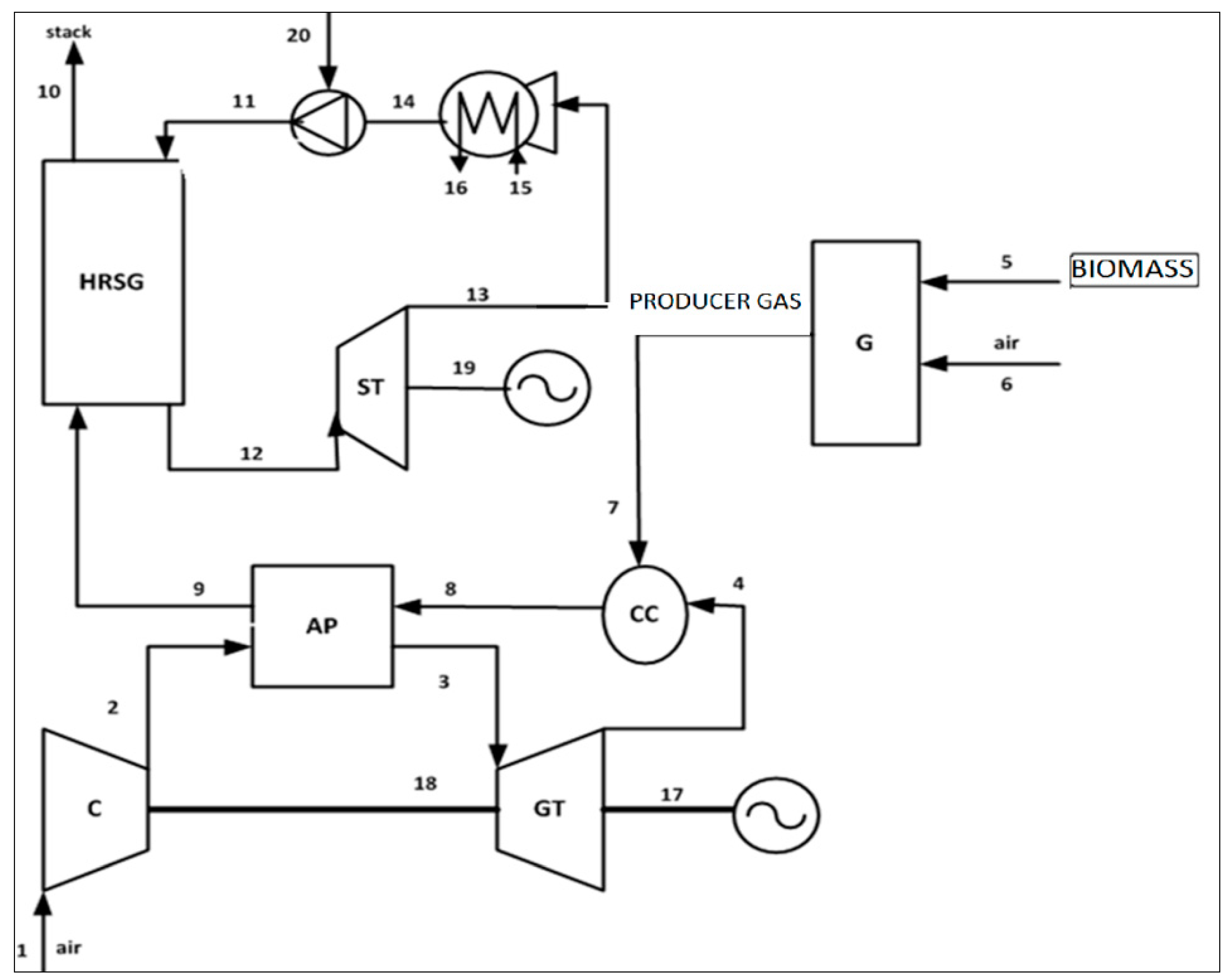
  • BGI-EFCC (Figure 1): Wood fuel is put into the gasifier, and producer gas from the gasifier and heated air from the gas turbine enter the combustion chamber. Exhaust gases from the combustion chamber heat the compressed air in a heat exchanger and then produce steam for the steam cycle in a heat recovery steam generator (HRSG).
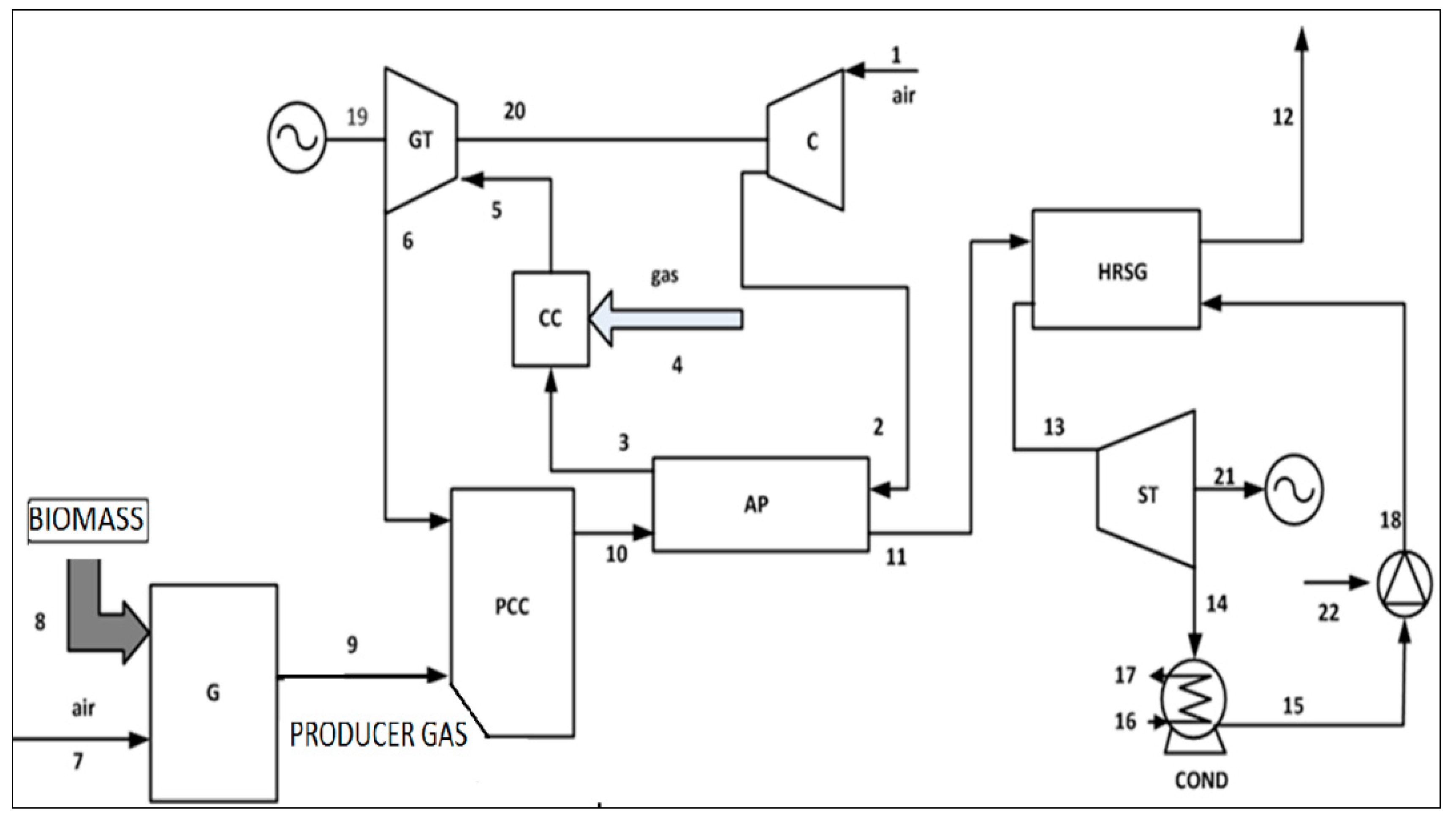
  • BGI-DFCC (Figure 2): This cycle uses a fuel mix of natural gas and biomass (wood) [12]. Air exiting the compressor passes through the pre-heater to the combustion chamber. Natural gas fuel is put into the combustion chamber. The producer gas from a downdraft gasifier is conveyed to the post-combustion unit where it mixes with the combustion gases from the gas turbine. Combustion exhaust gases from the post combustion unit preheat the airflow and pass through a HRSG, in which steam for the steam cycle is produced.
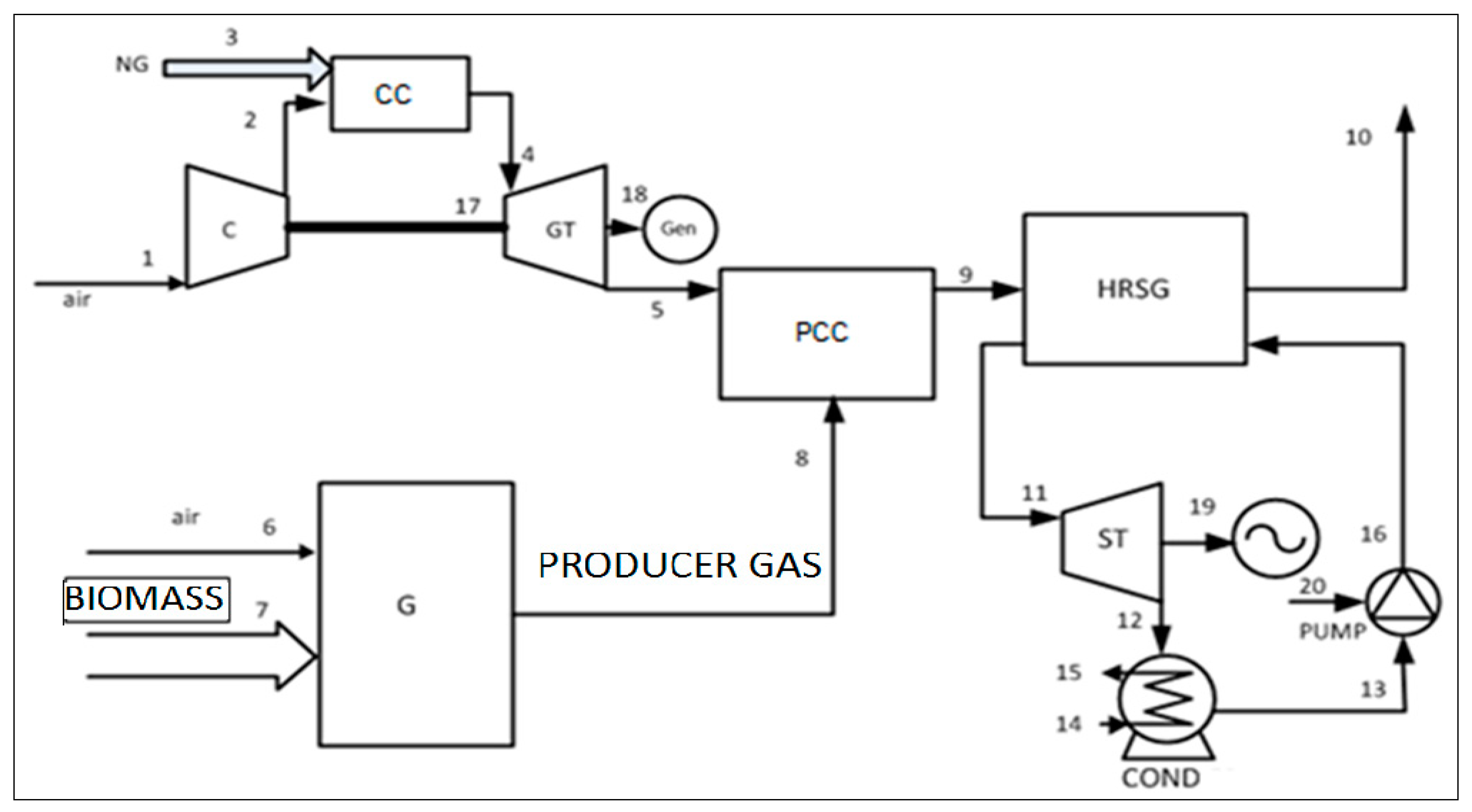
  • BGI-PFCC (Figure 3): This cycle also uses a fuel mix of natural gas and biomass (wood). The producer gas from a downdraft gasifier flows to the post-combustion unit, where it is combusted using the oxygen content of the combustion gases exiting the gas turbine. Unlike Figure 2, the exhaust gases from post combustion unit flow to the heat recovery steam generator.
Figure 1. Biomass gasification integrated externally fired combined cycle (BGI-EFCC).
Sustainability 07 01248 g001
Figure 2. Biomass gasification integrated dual-fuel combined cycle (BGI-DFCC).
Sustainability 07 01248 g002
Figure 3. Biomass gasification integrated post-firing combined cycle (BGI-PFCC).
Sustainability 07 01248 g003

3. Analyses

Numerous simplifications and assumptions are applied in the analyses. Air (79% nitrogen and 21% oxygen by vol.) enters the compressor at atmospheric conditions, i.e., P1 = 101.325 kPa and T1 = 298 K. The dry biomass fuel (wood) has a gravimetric composition of C: 50%, H: 6% and O: 44%, a calorific value of 449,568 kJ/kmol [16], and a 20% moisture content on a mass basis. Complete combustion occurs in the combustion chamber adiabatically and the pressure drop is 1%. The gasification equivalence ratio is 0.4188. The HRSG inlet temperature is 940 K, the HRSG pinch point temperature difference is 10 K, and the maximum steam temperature (TMAX,ST) is 850 K. The maximum pressure in the steam cycle (PMAX) is 8000 kPa and the condenser pressure is 8 kPa, while the minimum allowed steam quality (xout) is 0.9. The isentropic efficiency for the compressor (ηis,c) is 0.87 [11] and for the gas turbine (ηis,GT) is 0.89 [11], while the isentropic efficiency for the steam turbine (ηis,ST) is 0.9 [12] and for the pump (ηis,P) is 0.8. Pressure drops in the heat exchanger at the cold and hot sides are 3% and 1.5%, respectively, of the inlet pressures [11,17].
The performances of the cycles are assessed considering mass, energy and exergy balances [18,19,20,21], and chemical equilibrium for gasification [10,22]. An analysis by the authors of the BGI-EFCC is provided elsewhere [10] and the same analysis approach is applied for the BGI-DFCC and BGI-PFCC. We describe the gasifier analysis below [10].
A downdraft type gasifier with four zones (drying, pyrolysis, reduction, combustion) is considered. An equilibrium model is used, in which all gasifier reactions are taken to be in thermodynamic equilibrium. Prior to exiting the gasifier, pyrolysis products are assumed to have combusted and achieved equilibrium in the reduction zone, where the following reactions occur:
C + CO2 ↔ 2CO
C + H2O ↔ CO + H2
C + 2H2 ↔ CH4
The shift reaction is a combination of Equations (1) and (2):
CO + H2O ↔ CO2 + H2
Equilibrium constants for the methane formation equation of Equation (3) and the shift reaction, respectively, follow:
K 1 = P CH 4 ( P H 2 ) 2
K 2 = P CO 2 P H 2 P CO P H 2 O
We can express the overall gasification reaction as follows:
CH a O b N c + n H 2 O H 2 O + n air ( O 2 + 3.76 N 2 ) n 1 H 2 + n 2 CO + n 3 CO 2 + n 4 H 2 O + n 5 CH 4 + n 6 N 2
where n1, n2, n3, n4, n5 and n6 are the numbers of kmoles of the constituents of products. Additionally, n H 2 O is the kmoles of water per kmole of biomass and nair is the kmoles of oxygen per kmole of biomass in the gasification process.
With the equilibrium constants for methane formation and the shift reaction, mass and energy balances can be applied to the overall reaction of Equation (7) to determine values for n1 through n6 and the gasification temperature Tg or nair (depending on whether we know nair or Tg, respectively). The equilibrium constant can be written as
K 1 = n 5 n 1 2
for methane formation, and
K 2 = n 1 n 3 n 2 n 4
for the shift reaction. These equilibrium constants correspond to the change in the Gibbs functions for each reaction, as follows:
Δ G 1 R ¯ T g = lnK 1
Δ G 2 R ¯ T g = lnK 2
Assuming the gasifier is adiabatic, an energy balance for Equation (7) can be expressed as follows:
h ¯ f biomass o + n H 2 O × h ¯ f H 2 O o = n 1 ( h ¯ f H 2 o + Δ h ¯ H 2 ) + n 2 ( h ¯ f CO o + Δ h ¯ CO ) + n 3 ( h ¯ f C O 2 o + Δ h ¯ CO 2 ) + n 4 ( h ¯ f H 2 O o + Δ h ¯ H 2 O ) + n 5 ( h ¯ f CH 4 o + Δ h ¯ CH 4 ) + n 6 ( h ¯ f N 2 o + Δ h ¯ N 2 )
Since the right side of Equation (12) is evaluated at the gasification temperature, Δ h ¯ is the difference between the specific enthalpy of a component at the gasification temperature and at the reference environment temperature (Tref = 298 K).
The definition for exergy of fuel and exergy of product for three configurations are given in Table 1, Table 2 and Table 3. Cycle energy and exergy efficiencies, respectively, are determined as follows:
η = W ˙ net , cycle m ˙ fuel LHV fuel
ε = W ˙ net , cycle E ˙ F
Table 1. Fuel and product exergy definitions for BGI-EFCC.
ComponentExergy of FuelExergy of Product
Compressor E ˙ 18 E ˙ 2 E ˙ 1
Air Pre-heater E ˙ 8 E ˙ 9 E ˙ 3 E ˙ 2
Gas Turbine E ˙ 3 E ˙ 4 E ˙ 17 + E ˙ 18
Combustion Chamber E ˙ 7 E ˙ 8 E ˙ 4
Gasifier E ˙ 5 + E ˙ 6 E ˙ 7
HRSG E ˙ 9 E ˙ 10 E ˙ 12 E ˙ 11
Steam Turbine E ˙ 12 E ˙ 13 E ˙ 19
Condenser E ˙ 13 E ˙ 14 E ˙ 16 E ˙ 15
Pump E ˙ 20 E ˙ 11 E ˙ 14
Table 2. Fuel and product exergy definitions for BGI-DFCC.
ComponentExergy of FuelExergy of Product
Compressor E ˙ 20 E ˙ 2 E ˙ 1
Air Pre-heater E ˙ 10 E ˙ 11 E ˙ 3 E ˙ 2
Gas Turbine E ˙ 5 E ˙ 6 E ˙ 19 + E ˙ 20
Combustion Chamber E ˙ 4 E ˙ 5 E ˙ 3
Post Combustion Chamber E ˙ 9 E ˙ 10 E ˙ 6
Gasifier E ˙ 7 + E ˙ 8 E ˙ 9
HRSG E ˙ 11 E ˙ 12 E ˙ 13 E ˙ 18
Steam Turbine E ˙ 13 E ˙ 14 E ˙ 21
Condenser E ˙ 14 E ˙ 15 E ˙ 17 E ˙ 16
Pump E ˙ 22 E ˙ 18 E ˙ 15
Table 3. Fuel and product exergy definitions for BGI-PFCC.
ComponentExergy of FuelExergy of Product
Compressor E ˙ 17 E ˙ 2 E ˙ 1
Gas Turbine E ˙ 4 E ˙ 5 E ˙ 17 + E ˙ 18
Combustion Chamber E ˙ 3 E ˙ 4 E ˙ 2
Post Combustion Chamber E ˙ 8 E ˙ 9 E ˙ 5
Gasifier E ˙ 6 + E ˙ 7 E ˙ 8
HRSG E ˙ 9 E ˙ 10 E ˙ 11 E ˙ 16
Steam Turbine E ˙ 11 E ˙ 12 E ˙ 19
Condenser E ˙ 12 E ˙ 13 E ˙ 15 E ˙ 14
Pump E ˙ 20 E ˙ 16 E ˙ 13
The gasification results are validated by comparing them (see Table 4) with results from other experimental [23] and theoretical [22] studies, showing good agreement.
Table 4. Comparison of gasification constituent breakdown (in %) for model and experimental approaches, considering gasification at 800 °C of wood with 20% moisture.
ConstituentPresent ModelExperiment [23]Zainal Equilibrium Model [22]
H218.0115.2321.06
CO18.7723.0419.61
CH40.681.580.64
CO213.8416.4212.01
N248.742.3146.68
O20.001.420.00
Additionally, several parameters (pressure, temperature, mass flow rate) of each key stream in the BGI-EFCC, BGI-DFCC and BGI-PFCC plants at selected positions are listed in Table 5a–c, respectively.
Table 5. (a) Parameter values for key streams in the BGI-EFCC plant *; (b) Parameter values for key streams in the BGI-DFCC plant *; (c) Parameter values for key streams in the BGI-PFCC *.
StreamT (K)P (kPa) m ˙ (kg/s)
(a) Parameter Values for Key Streams in the BGI-EFCC Plant *
2590.50910.7016.55
4878.80103.6616.55
81520102.5421.02
10384.30101.1321.02
12850.008000.003.87
(b) Parameter Values for Key Streams in the BGI-DFCC Plant *
2590.50910.7016.89
6886.10103.6617.05
101283.00102.5419.60
12384.60101.1319.60
13850.008000.003.61
(c) Parameter Values for Key Streams in the BGI-PFCC *
2590.50910.7017.27
5893.90102.1417.62
9940.00101.1317.96
10384.90101.1319.96
12850.008000.003.30
* rp = 9, TIT = 1400 K, THRSH,IN = 940 K, W ˙ net = 10 MW.

4. Results and Discussion

Relations between Performance and Operating Parameters

The effect on cycle performance is investigated for various operating parameters. For the BGI-DFCC, the amount of natural gas is fixed at 0.01 kmol/s. Figure 4 shows the variation in energy efficiencies of the cycles with pressure ratios. The BGI-PFCC efficiency is 3% and 6% points higher than the corresponding BGI-DFCC and BGI-EFCC efficiencies, respectively. As pressure ratio changes, all efficiencies are observed to be maximized at particular values of the gas turbine inlet temperature. Nonetheless, the BGI-PFCC and BGI-DFCC have the lowest and highest optimum pressure ratios, respectively, for a fixed gas turbine inlet temperature (TIT = 1400 K).
Figure 4. Variation of cycle energy efficiencies with pressure ratio (TIT = 1400 K).
Sustainability 07 01248 g004
A similar result is observed for the cycle exergy efficiencies in Figure 5. The BGI-PFCC exergy efficiency is about 6% and 10% points higher than the BGI-DFCC and BGI-EFCC exergy efficiencies, respectively, mainly because the BGI-EFCC plant, unlike the BGI-DFCC and the BGI-PFCC plants, fires only biomass, and biomass fired systems have comparatively lower efficiencies. Much less biomass is used in the BGI-PFCC than the BGI-DFCC (see Table 5b,c) in which the BGI-DFCC plant consists of a heat exchanger, necessitating firing of more biomass.
Figure 5. Variation of cycle exergy efficiencies with pressure ratio (TIT = 1400 K).
Sustainability 07 01248 g005
Figure 6 and Figure 7 show the variations in the energy and exergy efficiencies of the cycles with gas turbine inlet temperature (TIT) for a compressor pressure ratio of 9. The efficiencies increase with TIT.
Figure 6. Variation of cycle energy efficiencies with gas turbine inlet temperature (rp = 9).
Sustainability 07 01248 g006
Figure 7. Variation of cycle exergy efficiencies with gas turbine inlet temperature (rp = 9).
Sustainability 07 01248 g007
Figure 8 shows the variation of the mass of air per mass of steam for the three cycles with pressure ratio changes, for TIT = 1400 K. As rp increases, the mass of air per mass of steam decreases for the BGI-PFCC, but the pressure ratio has little influence on the ratio for the BGI-EFCC and BGI-DFCC. This can be attributed to the fact that for the BGI-PFCC, unlike for the BGI-DFCC and the BGI-EFCC, the compressor delivery temperature is not directly influenced by the HRSG inlet gas temperature, which is constant. Clearly, the heat exchanger in the BGI-DFCC and the BGI-EFCC plants mitigates the influence of rp on this ratio. This quantity is highest for BGI-PFCC, followed by the BGI-DFCC and BGI-EFCC. However, increasing TIT decreases the mass of air per mass of steam for the BGI-EFCC and BGI-DFCC and increases this ratio for the BGI-PFCC (Figure 9).
Figure 8. Variation of mass of air per mass of steam for the cycles with rp (TIT = 1400 K).
Sustainability 07 01248 g008
Figure 9. Variation of mass of air per mass of steam for the cycles with TIT (rp = 9).
Sustainability 07 01248 g009
Exergy efficiencies for the components of the three configurations are shown in Figure 10 for the maximum energy efficiency condition. The gas turbine exergy efficiency is the highest for the three configurations, and the BGI-PFCC exhibits the highest gas turbine exergy efficiency. Since chemical reaction occurs in the post combustor, the combustor, and the gasifier, the associated irreversibilities are high. The BGI-DFCC combustion chamber has the highest exergy efficiency and the BGI-PFCC the lowest. In the post combustion chamber, the BGI-DFCC has the highest exergy efficiency. The exergy efficiencies are the same for the three configurations for the gasifier, steam turbine, pump, and HRSG, because they have the same conditions. The heat exchanger exergy efficiency is highest for the BGI-EFCC. The exergy efficiency differences of the compressor, for the three configurations, are minor; the highest value is observed for the BGI-PFCC. Furthermore, the compressor in three configurations has the second highest exergy efficiency of all components.
Figure 10. Exergy efficiency of BGI-EFCC, BGI-DFCC and BGI-PFCC components at maximum energy efficiency condition (TIT = 1400 K, THRSG, IN = 940 K).
Sustainability 07 01248 g010

5. Conclusions

Three biomass-based systems for electricity generation are successfully examined with energy and exergy analyses: the biomass gasification integrated externally fired combined cycle, the biomass gasification integrated dual-fuel combined cycle, and the biomass gasification integrated post-firing combined cycle. The following is concluded:
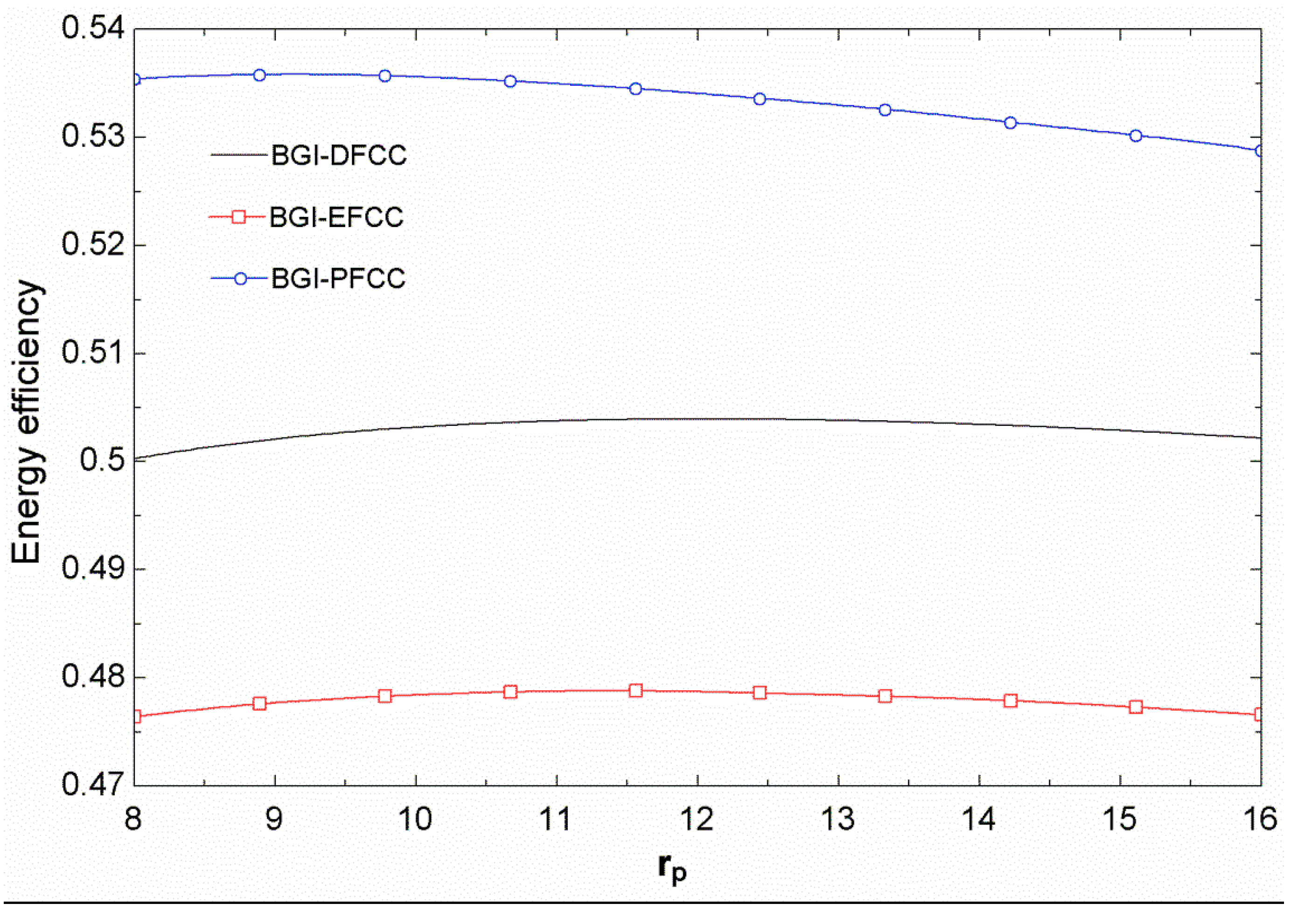
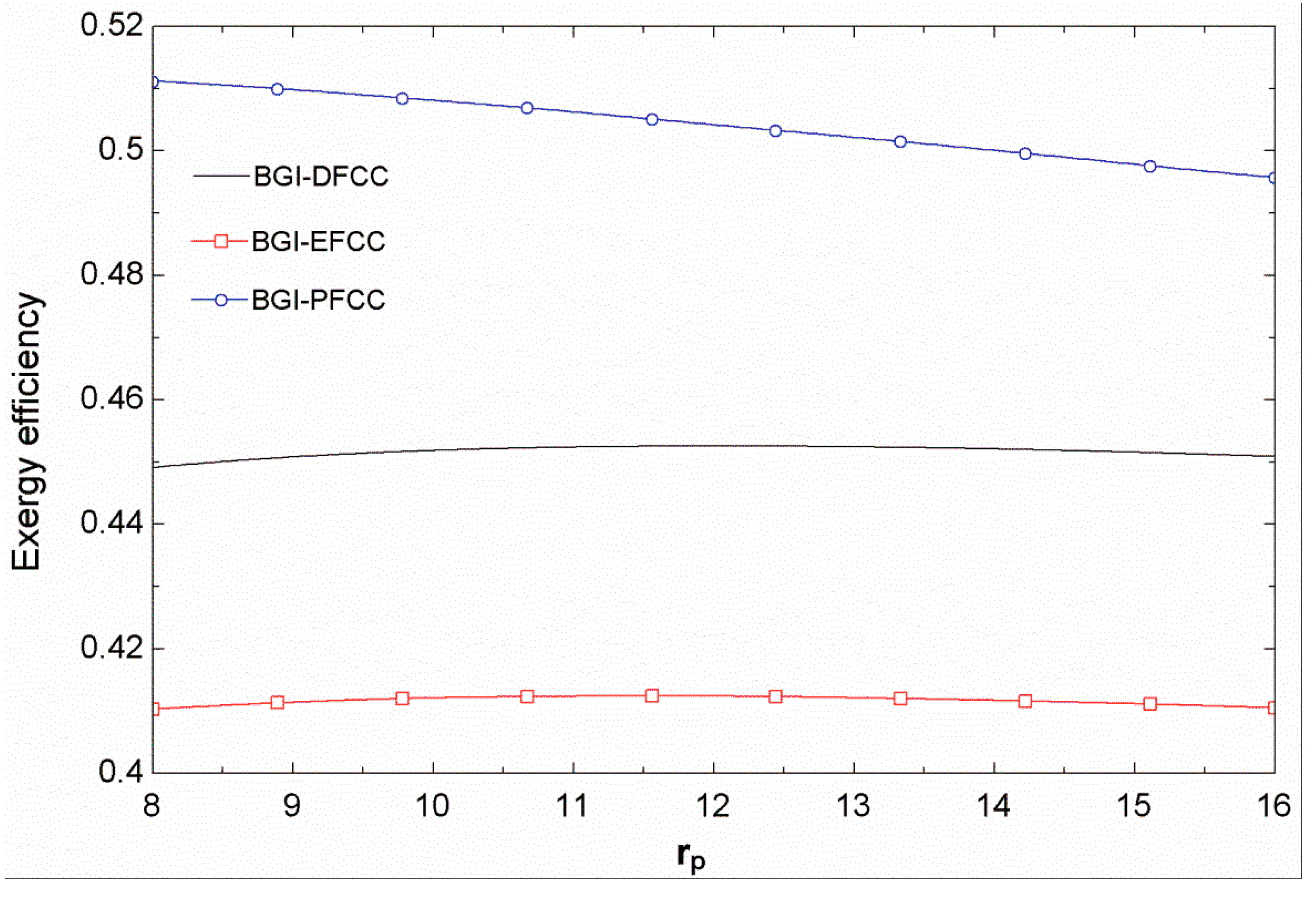
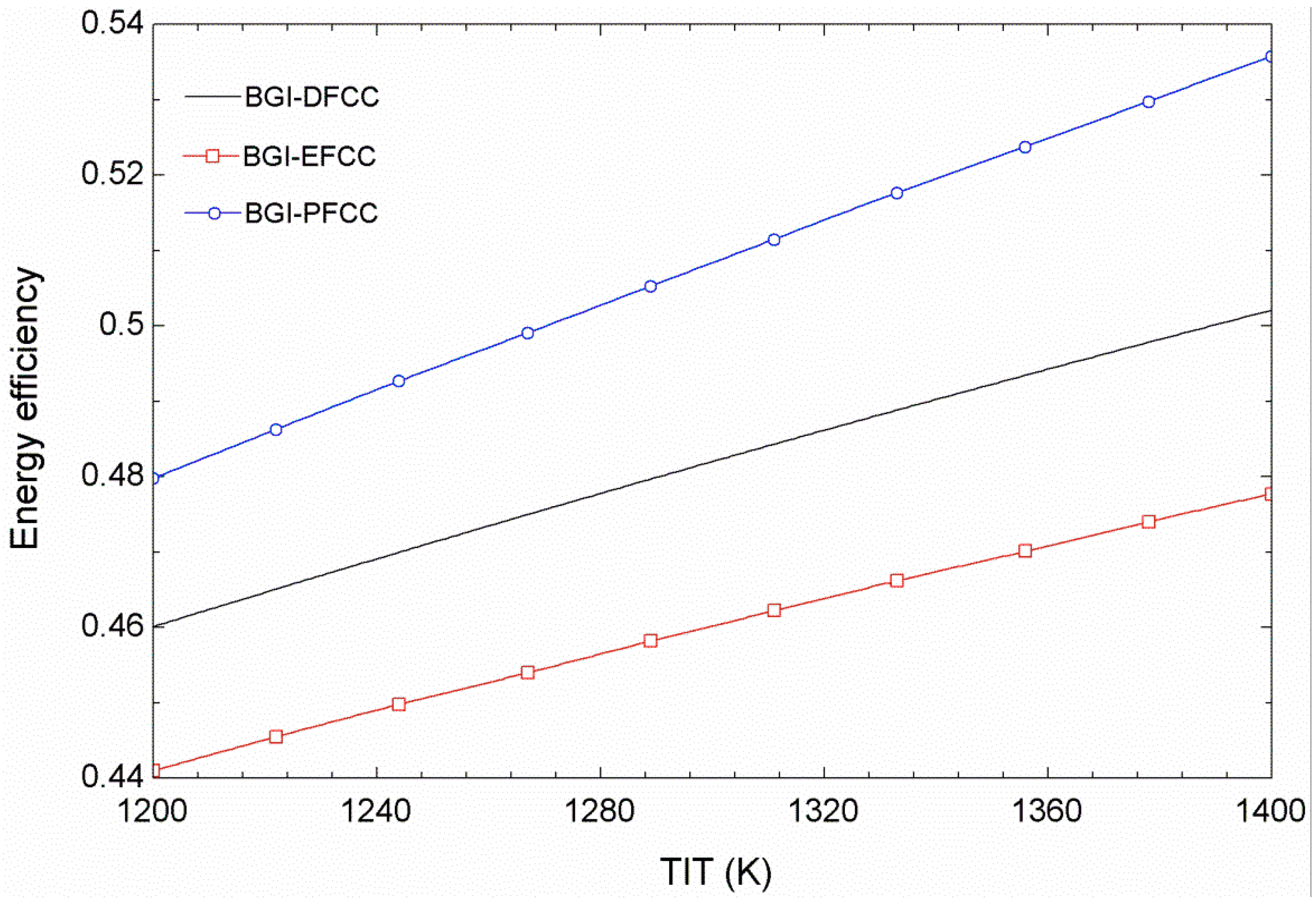
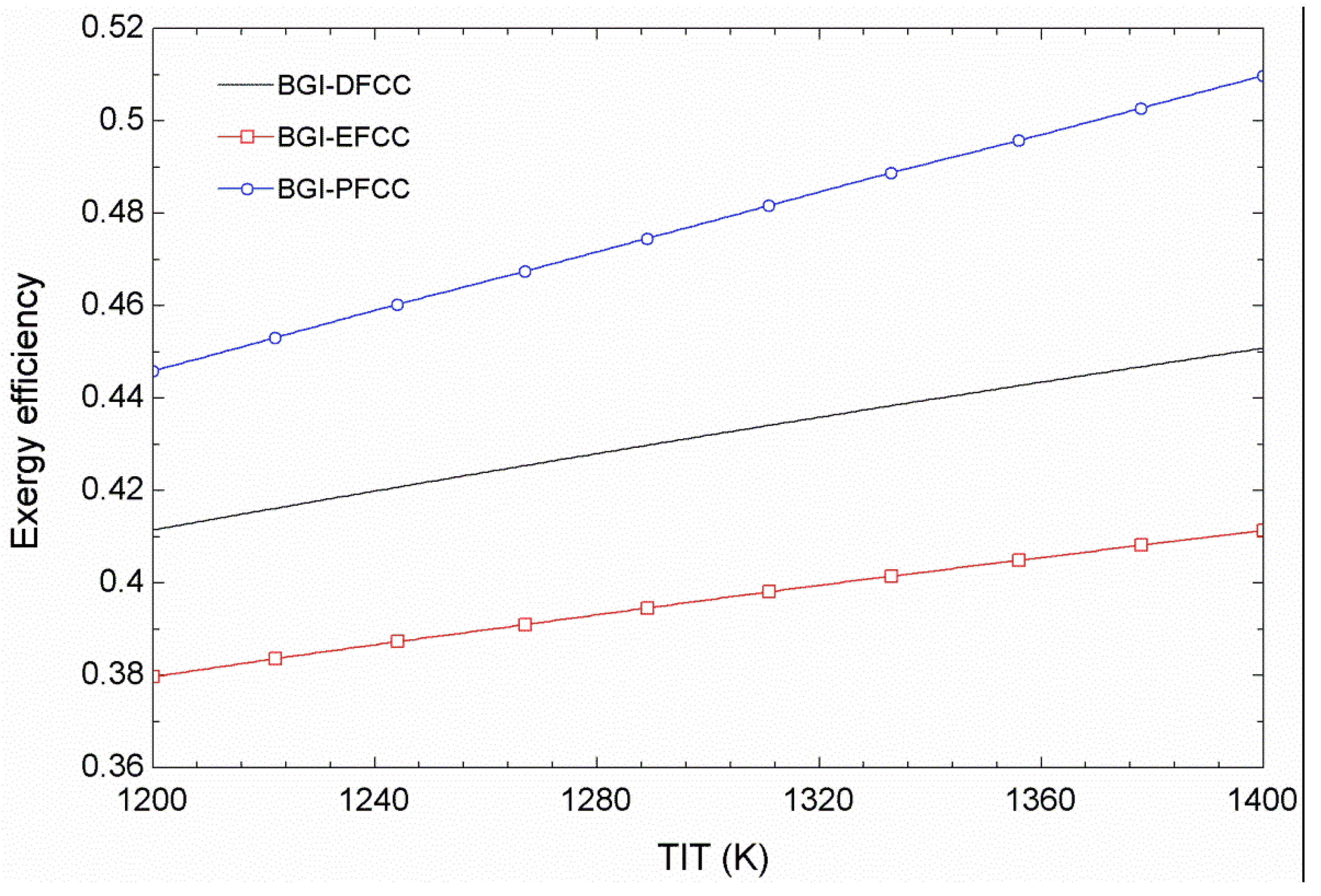
  • The BGI-PFCC energy efficiency is about 3% and 6% points higher than those of the BGI-DFCC and BGI-EFCC, respectively. Correspondingly, the exergy loss in BGI-PFCC is lower relative to the BGI-DFCC and BGI-EFCC. The energy and exergy efficiencies of the three biomass fired configurations are maximized at particular values of the compressor pressure ratios, and increasing the TIT raises the energy and exergy efficiencies for the BGI-PFCC, BGI-EFCC, and BGI-DFCC.
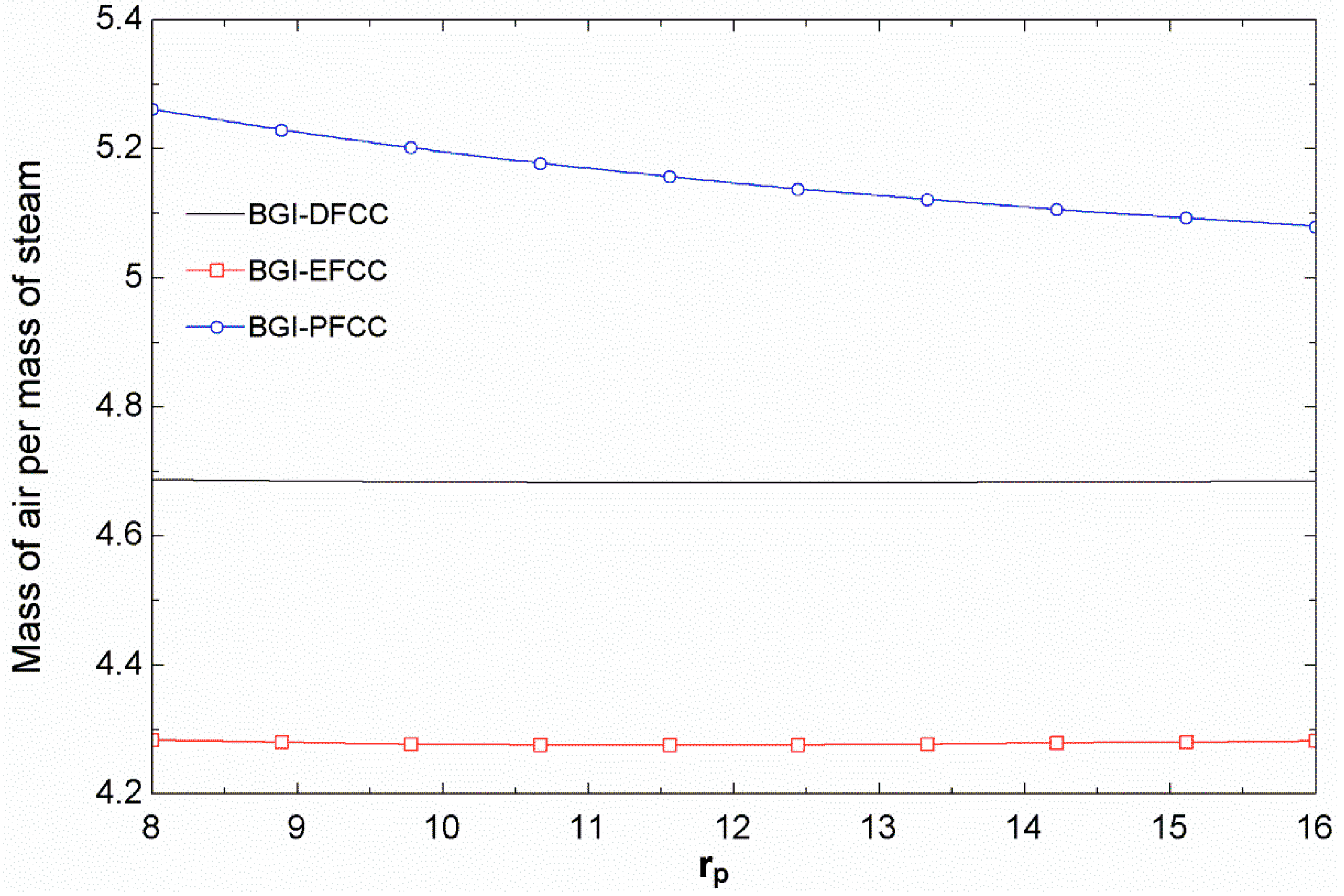
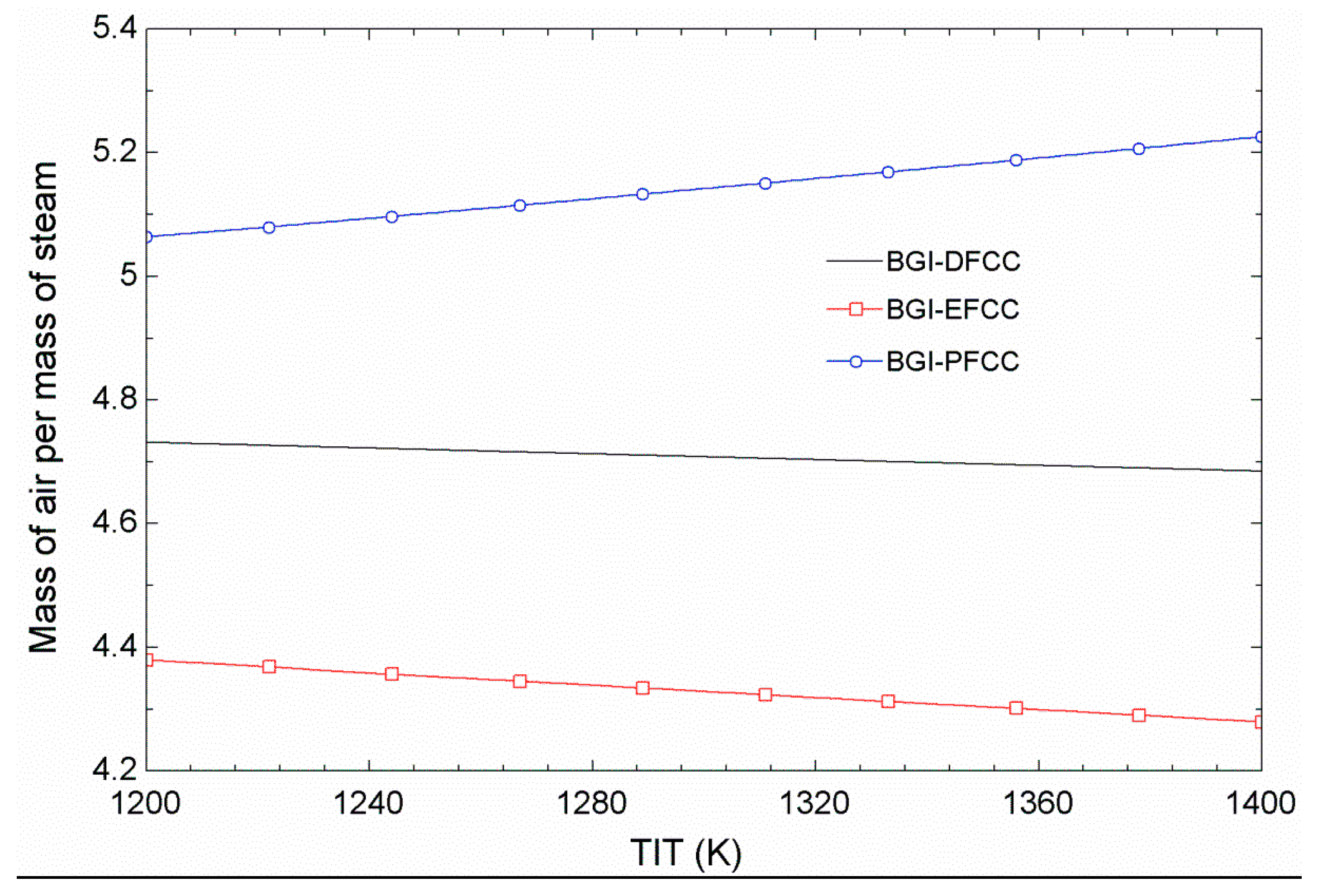
  • The mass of air per mass of steam is highest for the BGI-PFCC, but increasing the pressure ratio reduces this value for the BGI-PFCC and increases it slightly for the BGI-DFCC and BGI-EFCC. Increasing TIT raises the mass of air per mass of steam for the BGI-PFCC and decreases it slightly for the other cycles.
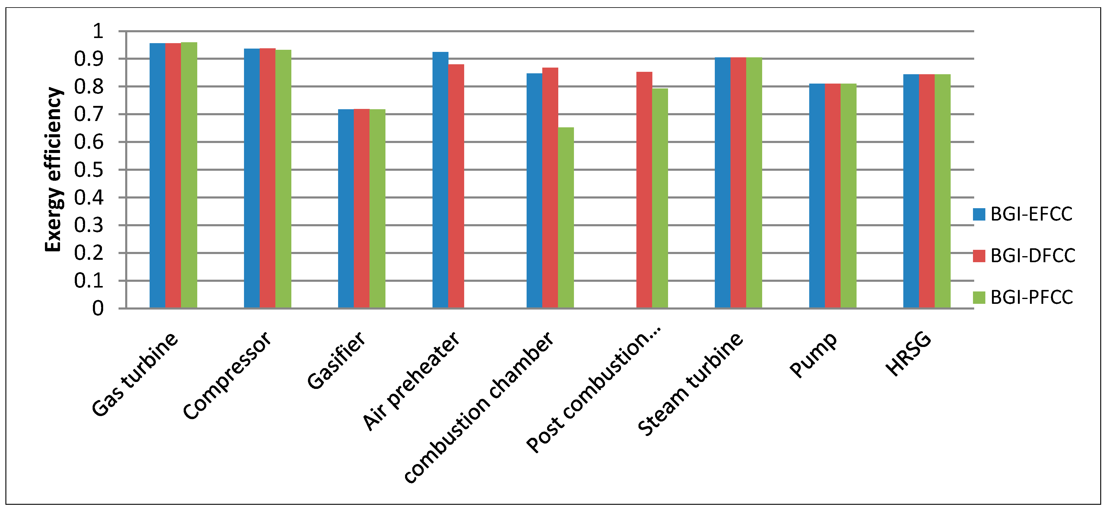
  • The exergy efficiencies for the components of the three configurations, determined for the maximum energy efficiency condition, indicate that the gas turbine exergy efficiency is the highest for three configurations, the BGI-PFCC exhibits the highest gas turbine exergy efficiency, the BGI-DFCC combustion chamber has the highest exergy efficiency, and the lowest exergy efficiency is for the BGI-PFCC. The post combustion chamber of the BGI-DFCC exhibits the highest exergy efficiency, while the heat exchanger exergy efficiency is highest for the BGI-EFCC.
  • Thermodynamic analysis for three cycles show that the BGI-PFCC is the more efficient cycle, followed in order by the BGI-DFCC and the BGI-EFCC plants. Also, the air preheater is a costly component in the BGI-DFCC and BGI-EFCC plants and is a negative feature of these plants. On the contrary, the BGI-EFCC plant has the highest exergy efficiencies for the air preheater and HRSG and only uses biomass. This last point makes the efficiencies of biomass plants comparatively low, but the enhanced availability, renewability and environmental characteristics can justify their uses. The results may prove beneficial for designers and engineers of such systems.

Author Contributions

Saeed Soltani, Hassan Athari, and Marc A. Rosen have done the technical, analysis, and writing parts, and Seyed Mohammad Seyed Mahmoudi and Tatiana Morosuk made contributions in the technical and analysis parts.

Nomenclature

AP
Air pre-heater
BGI-DFCC
Biomass gasification integrated dual-fuel combined cycle
BGI-EFCC
Biomass gasification integrated externally fired combined cycle
BGI-PFCC
Biomass gasification integrated post-firing combined cycle
E ˙
Exergy rate (kW)
G
Gasifier
GT
Gas turbine
h ¯ f 0
Enthalpy of formation (kJ/kmol)
HRSG
Heat recovery steam generator
K
Equilibrium constant (-)
LHV
Lower heating value (kJ/kg)
m ˙
Mass flow rate (kg/s)
n
Number of kmoles
P
Pump
Pi
Pressure at state i; partial pressure for species i (kPa)
PCC
Post combustion chamber
rp
Pressure ratio (-)
Ti
Temperature at state i (K)
TIT
Gas turbine inlet temperature (K)
W ˙ net
Net power (kW)
x
Steam quality (-)

Greek Letters

η
Energy efficiency (-)
η is , C
Isentropic efficiency of compressor (-)
η is , ST
Isentropic efficiency of gas turbine (-)
η is , ST
Isentropic efficiency of steam turbine (-)
ε
Exergy efficiency (-)

Subscripts

C
Compressor
CC
Combustion chamber
COND
Condenser
F
Fuel
GT
Gas turbine
in
Input
is
Isentropic
i
Index for thermodynamic state point
P
Product
ST
Steam turbine

Conflicts of Interest

The authors declare no conflict of interest.

References

  1. Al Kassir, A.; Gomez, J.G.; Mohamad, A.A.; Correa, E.M.C. A study of energy production from cork residues: Sawdust, sandpaper dust and triturated wood. Energy 2010, 35, 382–386. [Google Scholar] [CrossRef]
  2. Abuadala, A.; Dincer, I. Investigation of a multi-generation system using hybrid steam biomass gasification for hydrogen, power and heat. Int. J. Hydrog. Energy 2010, 35, 13146–13157. [Google Scholar] [CrossRef]
  3. Bhattacharya, A.; Manna, D.; Paul, B.; Datta, A. Biomass integrated gasification combined cycle power generation with supplementary biomass firing: Energy and exergy based performance analysis. Energy 2011, 36, 2599–2610. [Google Scholar] [CrossRef]
  4. Gnanapragasm, N.V.; Reddy, B.V.; Rosen, M.A. Optimum conditions for a natural gas combined cycle power generation system based on available oxygen when using biomass as supplementary fuel. Energy 2009, 34, 816–826. [Google Scholar] [CrossRef]
  5. Consonni, S.; Larson, E.D. Biomass-gasifier/aeroderivative gas turbine combined cycles. Part A—Technologies and performance modeling. J. Eng. Gas Turbines Power 1996, 118, 507–515. [Google Scholar] [CrossRef]
  6. Faaij, A.; van Ree, R.; Waldheim, L.; Olsson, E.; Oudhuis, A.; van Wijk, A.; Daey-Ouwens, C.; Turkenburg, W. Gasification of biomass wastes and residues for electricity production. Biomass Bioenerg. 1997, 12, 387–407. [Google Scholar] [CrossRef]
  7. Rodrigues, M.; Andre, P.C.F.; Walter, A. Techno-economic analysis of co-fired biomass integrated gasification/combined cycle systems with inclusion of economies of scale. Energy 2003, 28, 1229–1258. [Google Scholar] [CrossRef]
  8. Rosen, M.A.; Dincer, I. Exergoeconomic analysis of power plants operating on various fuels. Appl. Therm. Eng. 2003, 23, 643–658. [Google Scholar] [CrossRef]
  9. Tsatsaronis, G.; Pisa, J. Exergoeconomic evaluation and optimization of energy system—Application to the CGAM problem. Energy 1994, 19, 287–321. [Google Scholar] [CrossRef]
  10. Soltani, S.; Mahmoudi, S.M.S.; Yari, M.; Rosen, M.A. Thermodynamic analyses of an externally fired gas turbine combined cycle integrated with a biomass gasification plant. Energy Convers. Manag. 2013, 70, 107–115. [Google Scholar] [CrossRef]
  11. Datta, A.; Ganguly, R.; Sarkar, L. Energy and exergy analyses of an externally fired gas turbine (EFGT) cycle integrated with biomass gasifier for distributed power generation. Energy 2010, 35, 341–350. [Google Scholar] [CrossRef]
  12. Franco, A.; Giannini, N. Perspectives for the use of biomass as fuel in combined cycle power plants. Int. J. Therm. Sci. 2005, 44, 163–177. [Google Scholar] [CrossRef]
  13. Spath, P. Innovative Ways of Utilizing Biomass in a Cofiring Scenario with a Gas Turbine Integrated Combined Cycle System. Power Milestone Completion Report; National Renewable Energy Laboratory: Golden, CO, USA, 1995. [Google Scholar]
  14. Walter, A.; Rodrigues, M.; Overend, R. Feasibility of co-firing (Biomass + Natural Gas). In Proceedings of The Fourth Biomass Conference of the Americas, Oakland, CA, USA, 29 August–2 September 1998; Elsevier: Oxford, UK, 1999; Volume 2, pp. 1321–1327. [Google Scholar]
  15. Walter, A.; Llagostera, J.; Gallo, W.L.R. Impact of gas turbine de-rating on the performance and economics of BIG-GT cycles. In Proceedings of the Advanced Energy Systems Division, ASME International Mechanical Engineering Congress and Exposition, Anaheim, CA, USA, 15–20 November 1998; pp. 67–72.
  16. Robert, H.P.; Don, W.G. Perry’s Chemical Engineers Hand Book, 6th ed.; McGraw Hill: New York, NY, USA, 1984. [Google Scholar]
  17. Cocco, D.; Deiana, P.; Cau, G. Performance evaluation of small size externally fired gas turbine (EFGT) power plants integrated with direct biomass dryers. Energy 2006, 31, 1459–1471. [Google Scholar] [CrossRef]
  18. Moran, M.J.; Shapiro, H.N.; Boettner, D.D.; Bailey, M.B. Fundamentals of Engineering Thermodynamics, 7th ed.; Wiley: New York, NY, USA, 2011. [Google Scholar]
  19. Dincer, I.; Rosen, M.A. Exergy: Energy, Environment and Sustainable Development, 2nd ed.; Elsevier: Oxford, UK, 2013. [Google Scholar]
  20. Kotas, T.J. The Exergy Method of Energy Plant Analysis; Butterworths: London, UK, 1985. [Google Scholar]
  21. Szargut, J.; Styrylska, T. Approximate evaluation of exergy of fuels. Brennst. Warme Kraft 1964, 16, 589–596. [Google Scholar]
  22. Zainal, Z.A.; Ali, R.; Lean, C.H. Prediction of performance of downdraft gasifier using equilibrium modeling for different biomass materials. Energy Convers. Manag. 2001, 42, 1499–1515. [Google Scholar] [CrossRef]
  23. Alauddin, Z.A. Performance and Characteristics of a Biomass Gasifier System. Ph.D. Thesis, University of Wales, College of Cardiff, Cardiff, UK, 1996. [Google Scholar]

