Article

Simplified Heat and Mass Transfer Model for Cross-Flow and Countercurrent Flow Packed Bed Tower Dehumidifiers with a Liquid Desiccant System

1
Department of Energy and Refrigerating Air-Conditioning Engineering, National Taipei University of Technology, Taipei 10608, Taiwan
2
Multiflow Technology, Taichung 414, Taiwan
*
Author to whom correspondence should be addressed.
Sustainability 2016, 8(12), 1264; https://doi.org/10.3390/su8121264
Submission received: 29 August 2016 / Revised: 15 November 2016 / Accepted: 21 November 2016 / Published: 3 December 2016
(This article belongs to the Section Energy Sustainability)

Abstract

:
A mathematical model is developed using the Matlab/Simulink platform to investigate heat and mass transfer performance of cross-flow and counterflow dehumidifiers with Lithium Chloride (LiCl) solution. In the liquid desiccant dehumidifier, the orthogonal polynomial basis is used to simulate the combined processes of heat and mass transfer. The temperature profiles on cross-flow and countercurrent flow dehumidifiers are demonstrated. The resultant counter flow air changes the temperature profile of the LiCl solution in the longitudinal direction because of the drag forces. In addition, when inlet airflow rate reaches 15 kg·s−1, the temperature effect becomes less obvious and may be reasonably negligible. Under these conditions, the air changes the design factor and determines the interfacial temperature. It is demonstrated that the mathematical model can be of great value in the design and improvement of cross-flow and countercurrent flow dehumidifiers.

1. Introduction

The liquid-desiccant air-conditioning (LDAC) system offers the advantage of removing the latent load and various pollutants from the air simultaneously, and has been long accepted [1,2]. Compared with the conventional cooling coils system, the overall energy use of an LDAC system is reduced and the lower grade energy sources that can be used in the system are less expensive than electricity [3,4,5,6,7]. The dehumidifier is an important part of the LDAC and greatly affects the performance of the whole system. The package type dehumidifier has gained more attention because of its closeness in contrast to the other types [8]. Many parameters affect the heat and mass transfer processes, such as relative airflow direction through the desiccant, packing type and material and the inlet parameters of the air and the desiccant. Because dehumidification is a very complicated process, researchers have studied it using different approaches. Past theoretical or experimental studies have often addressed specific applications.
Liu et al. [9] used LiBr solution in experiments on the regenerator. They measured the thermal and regenerated air performances of the desiccant solution and the regenerated airflow in cross-flow and countercurrent flow structures. They also showed that the dimensionless correlation of mass transfer was in agreement with the findings. Fumo and Goswami [10] also used lithium chloride (LiCl) desiccant solution to test the performance of packaged tower type absorbers and regenerators. Gommed and Grossman [11] built and measured the performance of a 16-kW absorber and regenerator prototype system. Zhang et al. [12] used LiCl solution to analyze the mass transfer natives on a packing structural absorber and regenerator, and built overall mass transfer interrelations within a deviation of 20% from experimental values. Mohammad et al. [13] used statistical software (SPSS (SPSS Inc., Chicago, IL, USA, 1996)) to derive useful relevance between input and output parameters in the dehumidifier/regenerator. Their statistical analysis showed that variations in inlet humidity and mass flow rate and solution temperature have implied effect on variation of water condensation rate in dehumidifiers, with p < 0.01. In addition, variations in inlet air mass flow rate and solution temperature have significant effects on variation of water condensation rate in the regenerator with p < 0.01. Bassuoni [14] designed and experimentally used Calcium Chloride (CaCl2) solution desiccant and tested a packing structural cross-flow desiccant dehumidification system. They found that an increase in the air and desiccant flowrates increases the moisture removal rate and mass transfer coefficient of the dehumidifier/regenerator. The effectiveness of the dehumidifier/regenerator reduces and increases when the air and desiccant flowrate, respectively, increase. While structured packing structural thickness increases, the moisture removal rate and the effectiveness of dehumidifier/regenerator will also increase.
Some theoretical models have been used to analyze dehumidifier performance, in combination with experimental data. For countercurrent flow dehumidifiers, Park and Jeong [15] proposed second-order polynomials to calculate effectiveness of dehumidification in packed or sprayed tower LDAC systems, focusing on five operational parameters of humidity ratio and inlet temperature of the air, initial concentration and outlet temperature of the desiccant and liquid-to-gas ratio. Babakhani [16] used the Laplace transformation method to solve a mathematical model of an air dehumidification process. Wassan et al. [17] showed the mathematical model of an adiabatic dehumidifier of the LDAC system and used the regression approach to derive a mathematical correlation between humidity ratio and the enthalpy, and then get proper air-to-desiccant countercurrent flow direction. Rahimi and Babakhani [18] developed a non-isothermal mathematical model for a countercurrent flow packed bed dehumidifier to investigate the effect of different empirical relationships and showed various models of the bed performance [19,20,21,22]. Kumar and Asati [23] developed a mathematical model from the control volumes of a dehumidifier/regenerator and a differential form of non-linear coupled first-order differential governing equations. They used the mass of condensation of the air and dehumidification effectiveness to monitor performance of a dehumidifier, and also derived the mass of evaporation of the air and regenerator effectiveness to monitor performance of a regenerator. Concerning the cross-flow dehumidifier, Niu [24] derived the mass and energy balance equations on a two-dimensional mathematical model to account for the performance of heat and mass transfer in an air dehumidifier. Numerical results are in agreement with experimental findings. Bassuoni [25,26] recommended a simple analytical model of mass and energy balances in a cross-flow liquid desiccant dehumidifier with CaCl2 desiccant solution. The model was calibrated with experimental data described in [14]. Lu et al. [27] established computational fluid dynamic (CFD) models for the countercurrent flow LDAC set on the volume of fraction (VOF) and renormalization group (RNG) k-ε turbulence model and evaluated the dynamic formation process of unsteady countercurrent flow. They showed that the performance with respect to the absorption and regeneration process of the liquid desiccant dehumidifier was apparently due to the expanded contact area.
The novel liquid-to-air membrane energy exchanger (LAMEE), under development, is expected to eliminate the desiccant solution aerosol carry-over problem [28,29]. It uses semi-permeable membranes to separate air and desiccant solution streams. These membranes let heat and moisture transfer between the air and desiccant solution streams simultaneously, but reject transfer of any liquid droplets. Bergero and Chiari [30] used a hollow-fiber membrane contactor to investigate air humidification/dehumidification processes experimentally and theoretically. The results showed that variation in specific humidity reduces as the volumetric air flow rate increases and does not significantly rely on the liquid mass flow rate. The effectiveness of the cross-flow contactor diminishes slightly as the air flow rate increases. Theoretical predictions show good agreement with experimental results and any differences are within the range of measurement error. Zhang [31] developed an analytical model for a semi-permeable hollow-fiber LAMEE. The model estimated sensible cooling and air dehumidification effectiveness that is accurate and convenient and this has been experimentally validated. The total number of transfer units for sensible heat and the overall Lewis number are the most dominant parameters that influence heat and mass transfer. Abdel-Salam et al. [32] deal with a comprehensive review of the design and performance of LAMEE as follows:
  • The effectiveness of different types of LAMEEs for air cooling and dehumidifying was between 60% and 94%.
  • The effectiveness of a flat-plate LAMEE in summer operating conditions is higher than in winter operating conditions.
  • The performance of LAMEEs can be significantly reduced if there is flow maldistribution.
  • On the air and liquid sides hollow-fiber LAMEEs endure large pressure drops.
Abdel-Salam et al. [33] also proposed a numerical model to show the effects of air and desiccant solution channel widths on the performance of a two-fluid flat-plate LAMEE when used as supply air dehumidifier and a diluted desiccant solution regenerator. They found there exists an optimal air channel width for flat-plate LAMEEs with flow maldistribution due to random variations in the air channel width. Decreasing the air channel width below this optimal value results in a decrease in effectiveness. The optimum nominal air channel widths for flat-plate LAMEEs may be 5–6 mm and 1–2 mm. Ge et al. [34] compared the LAMEE with packed bed. At the same air pressure drop, the latent and total effectiveness of the LAMEE is higher than for the packed bed, at 13% and 20%, respectively. But mass transfer performance of the packed bed is higher than for the LAMEE, at 16% with the same heat and mass transfer area. The overall heat and mass transfer resistance of the membrane rely on the width of the air channel, and are 6%~12% and 26%~43%, respectively.
In summary, the majority of the available models in open literature were generally built on the assumption that all components operate in a steady-state using time-step or dimension-step simulations. In order to understand performance of dehumidifier, it is necessary to consider effects of component operation in a transient state. Ruivo et al. [35], based on the lumped-capacitance method used a one-dimensional formulation to investigate the validity of two simplifying approaches of neglecting the transversal heat and mass transfer resistance within the porous medium and cancelling only the thermal resistance on desiccant wheel. They showed that the Biot number for surface diffusion is several orders of magnitude higher than the corresponding thermal Biot number. Mandegari et al. [36] used an unsteady state one-dimensional model for assessment of energy consumption by the desiccant wheel. They showed that the best operating condition from regeneration heat standpoint will be accomplished at the lowest regeneration temperature and highest wheel speed. The objective in this study is to develop a mathematical model that can be used to advance the design and performance improvement of cross-flow and countercurrent flow dehumidifier, using LiCl solution as the liquid desiccant. We present a theoretical analysis of the heat and mass transfer between the air and desiccant within cross-flow and countercurrent flow dehumidifiers, using two-dimensional orthogonal collocation. Our model is based on the assumption that all components operate in a transient state, using a time-step simulation. The model can present field distributions of the temperature and concentration inside the cross-flow and countercurrent flow dehumidifiers. The analytical solutions optimize the device designs.

2. Physical Properties of the Desiccant

Compared with lithium bromide (LiBr), LiCl, and CaCl2, LiCl offers higher efficiency for the dehumidifier [28]; therefore, this study used LiCl as the dehumidification desiccant. The basic operational condition of LiCl solution is fixed at 27 °C temperature and 35% mass concentration. The physical properties of LiCl solution/operating parameters and design parameters of the dehumidifier are listed in Table 1 and Table 2, respectively.

3. Theoretical Model

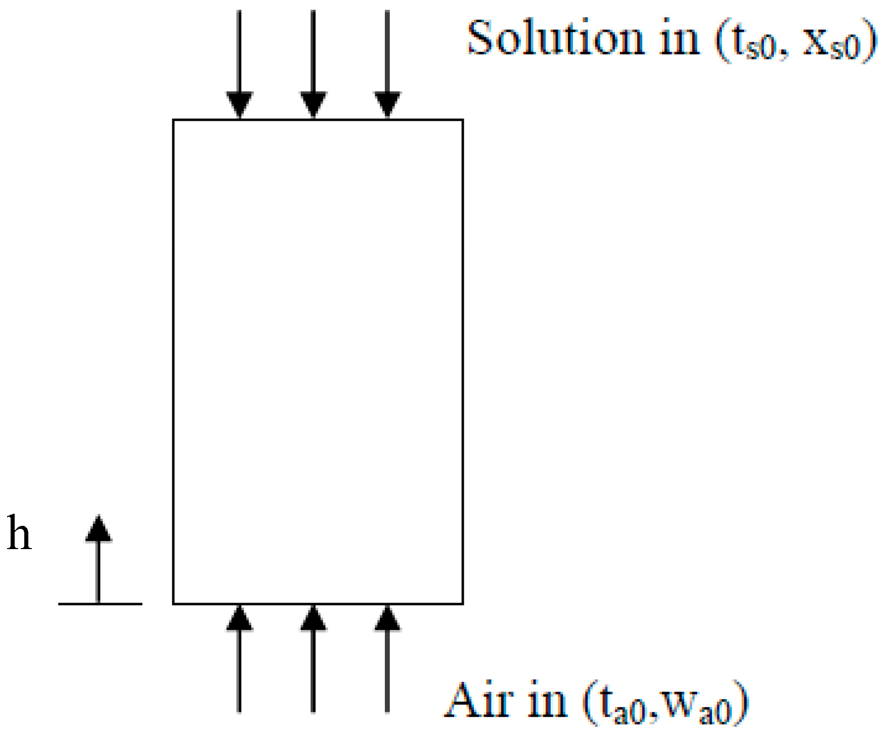
3.1. Counter-Flow Dehumidifier

The schematic of the counter-flow packed bed dehumidifier is shown in Figure 1. Dehumidified air and diluted desiccant solution as the moisture is transported from the air to the desiccant solution in the dehumidifier is shown.

3.1.1. Governing Equation

The assumptions of the model for humid air are as follows:
(1)
Humid air is the mixture of an ideal gas, and Dalton’s law of partial pressures is true [35].
(2)
One-dimensional transient heat and mass transfer are considered [36].
(3)
Air flow is uniform [37].
(4)
Constant specific heat capacities are for dry air and liquid desiccant.
(5)
Compared with the gas phase, the liquid phase neglects thermal resistance.
(6)
The surroundings have no heat exchange; and
(7)
Liquid desiccant neglects vaporization.
The governing equations can be mathematically derived from appropriate balances applied to an infinitesimal control volume of the air and solution desiccant flowing through the dehumidification tower, leading to the following lumped-capacitance model with the definitions of number of dimensionless mass transfer unit (NTUm) and Lewis number (Le) [21,36,38,39,40]:
Air side
d ω a d t = v a d ω a d x N T U m × v a H ( ω e ω a )
d h e , a d t = v a d h e , a d x N T U m × L e × v a H [ ( h e , e h e , a ) + r ( 1 L e 1 ) ( ω e ω a ) ]
with boundary conditions
t = 0, ωa = ωa,i, he,a = he,a,I
h = 0 ,   d ω a d x = 0 ,   d h e , a d x = 0
Solution desiccant side
d m ˙ s d t = m ˙ a d ω a d t
m ˙ a d h e , a d t = h s d m ˙ s d t + m ˙ s d h e , s d t
d X s d t = X s m ˙ s d m ˙ s d t
N T U m = α m A m ˙ a
L e = α α m c p , m
where v is air velocity, NTUm is the number of dimensionless mass transfer unit, Le is Lewis number, t is time, h is height of dehumidifier, H is total height of dehumidifier, he is enthalpy, ω is humidity ratio, r is water vaporization latent heat, m ˙ is mass flow rate, X is desiccant solution concentration, A is heat and mass transfer area, α is heat transfer coefficient, αm is mass transfer coefficient, cp,m is specific heat of humid air. The subscripts a, e, and s stand for air, air in equilibrium with solution desiccant, and solution desiccant, respectively.

3.1.2. Non-Dimensional Formulation

Using the non-dimensional parameters
ξ = x H ,   W ˙ a = ω a ω a , 0 ,   H ˙ a = h e , a h e , a , 0 ,   H ˙ s = h e , s h e , e , 0 , p ,   M ˙ s = m ˙ s m ˙ a , 0 ,   X s = x s x e , 0 , p
The dimensionless representation of the governing equations is as follows [41]:
Air side
W ˙ a t = v a H W ˙ a ξ N T U m × v a H ( ω e ω a , 0 W ˙ a )
H ˙ a t = v a H H ˙ a ξ N T U m × L e × v a H [ ( h e , e h e , a , 0 H ˙ a ) + γ ( ω a , 0 h a , 0 ) ( 1 L e 1 ) ( ω e ω a , 0 W ˙ a )
Solution desiccant side
M ˙ s t = m ˙ a ω a , 0 m ˙ a , 0 W ˙ a t
H ˙ s t = m ˙ a h e , a , 0 m ˙ a , 0 h e , e , 0 , p 1 M ˙ s H ˙ a t H ˙ s M ˙ s M ˙ s t
X ˙ s t = X ˙ s M ˙ s M ˙ s t
where W ˙ is dimensionless humidity ratio, ξ is water concentration in liquid desiccant, M ˙ is dimensionless mass flow rate, H ˙ is dimensionless enthalpy, X ˙ is dimensionless desiccant solution concentration.

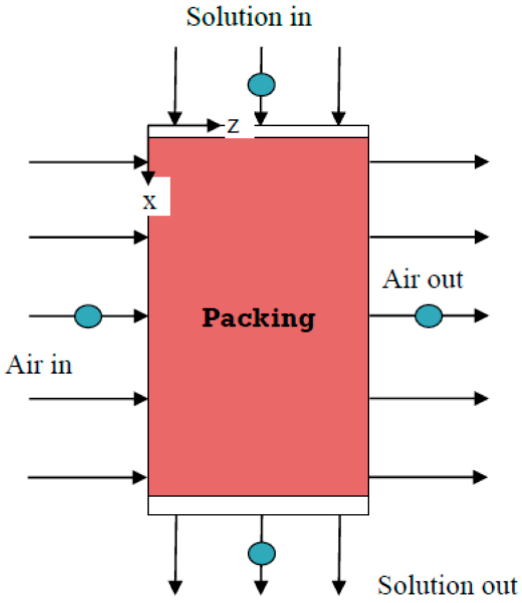
3.2. Cross-Flow Dehumidifier

The schematic of the cross-flow packed bed dehumidifier is shown in Figure 2. Packing is set inside the dehumidifier to expand the heat and mass transfer area between the air and liquid desiccant. The liquid desiccant is sprayed from the top and the air is transported into the dehumidifier from the left.

3.2.1. Governing Equation

The model described here is based on the following assumptions:
(1)
The heat and mass transfer can be simplified to a two-dimensional analysis.
(2)
The air and liquid desiccant uniformly enter the dehumidifier.
The governing equations of heat and mass transfer for the lumped-capacitance model are as follows [21,38,40,41,42,43,44]:
Air side
ω a t + v ω a = D 2 ω a + S ω a
S ω a = N T U m × v z L ( ω e ω a )
ω a t = v z ω a z + N T U m × v z L ( ω e ω a )
h e , a t = v z h e , a z + N T U m × L e × v z L [ ( h e , e h e , a ) + γ ( 1 L e 1 ) ( ω e ω a ) ]
with boundary conditions defined as the following:
t = 0, ωa = ωa,i, he,a = he,a,i
z = 0 ,   d ω a d z = 0 ,   d h e , a d z = 0
Solution desiccant side
( m ˙ a ω a + m ˙ s ) t + [ ( m ˙ a ω a + m ˙ s ) v ¯ ] = 0
( m ˙ a ω a + m ˙ s ) t + v ¯ ( m ˙ a ω a + m ˙ s ) + ( m ˙ a ω a + m ˙ s ) ( v ¯ ) = 0
m ˙ a ω a t + m ˙ s t = ( v z + v x ) ( m ˙ a ω a z + m ˙ s x )
m ˙ s t = m ˙ a ω a t v z m ˙ a ω a z v x m ˙ s x
( m ˙ a h e , a + m ˙ s h e , s ) t + [ ( m ˙ a h e , a + m ˙ s h e , s ) v ¯ ] = 0
m ˙ a h e , a t + h s m ˙ e , s t + m ˙ s h e , s t = ( v z + v x ) ( m ˙ a ω a z + h s m ˙ s x + m ˙ s h e , s x )
h e , s t = m ˙ a m ˙ s h e , a t h e , s m ˙ s m ˙ s t v z m ˙ a m ˙ s h e , a z v x ( h e , s m ˙ s m ˙ s x + h e , s x )
( m ˙ s x s ) t + [ ( m ˙ s x s ) v ¯ ] = 0
m ˙ s x s t + x s m ˙ s t = v x ( m ˙ s x s x + x s m ˙ s x )
x s t = x s m ˙ s m ˙ s t v x ( x s x + x s m ˙ s m ˙ s x )
with boundary conditions defined as the following:
t = 0, ωa = ωa,i, he,a = he,a,i

3.2.2. Non-Dimensional Formulation

Using the non-dimensional parameters
ξ = x H ,   η = z L ,   W ˙ a = ω a ω a , 0 ,   H ˙ a = h e , a h e , a , 0 ,   H ˙ s = h e , s h e , e , 0 , p ,   M ˙ s = m ˙ s m ˙ a , 0 ,   X ˙ s = x s x e , 0 , p ,   h e , e , 0 , p = 2 h e , e , 0 ,   X ˙ s , 0 , p = x s , 0 0.9
If m ˙ a > 1, then m ˙ a , 0 = m ˙ a × R ; if m ˙ a 1 , then m ˙ a , 0 = m ˙ a R .
The dimensionless representation of the governing equations is as follows [42,43]:
Air side
W ˙ a t = v z L W ˙ a η + N T U m × v z L ( ω e ω a , 0 W ˙ a )
H ˙ a t = v z L H ˙ a η + N T U m × L e × v z L [ ( h e , e h e , a , 0 H ˙ a ) + γ ( 1 L e 1 ) ( ω a , 0 h e , a , 0 ) ( ω e ϖ a , 0 ω a ) ]
Solution desiccant side
M ˙ s t = m ˙ a m ˙ a , 0 ω a , 0 W ˙ a t v z L m ˙ a m ˙ a , 0 ω a , 0 W ˙ a η v x H M ˙ s ξ
H ˙ s t = m ˙ a M ˙ s m ˙ a , 0 h e , a , 0 h e , e , 0 , p H ˙ a t H ˙ s M ˙ s M ˙ s t v z L m ˙ a M ˙ s m ˙ a , 0 h e , a , 0 h e , e , 0 , p H ˙ a η v x H ( H ˙ s M ˙ s M ˙ s ξ + H ˙ s ξ )
X ˙ s t = X ˙ s m ˙ s M ˙ s t v x H ( X ˙ s ξ + X ˙ s m ˙ s M ˙ s ξ )

3.3. Orthogonal Collocation Method

The spectral collocation method uses the orthogonal polynomial basis understood for its efficiency with respect to accuracy, despite a relatively small number of collocation points, with N being used to solve the problems. Explicitly, the first order derivative y(N) states the trial function as [45,46]:
y ( N ) ( x ) = y ( 1 ) + ( 1 x 2 ) i = 0 N 1 a i P i ( x 2 )
0 1 ( 1 x 2 ) P i ( x 2 ) P N ( x 2 ) x d x = C i δ i j j =   1 ,   2 ,   ...   ,   i 1
The Jacobian polynomial equation is used to satisfy the above mentioned equation.
C i = [ Γ ( a 2 ) ] 2 Γ ( i + 1 ) Γ ( i + 2 ) ( 4 i + a + 2 ) Γ ( i + a 2 ) Γ ( i + a 2 + 1 ) i   =   1 ,   2 ,   ...   ,   N
Following Villadsen and Stewart, the numerical derivation of the function is as follows [47]:
d y ( N ) d x | x i = j = 1 N + 1 A i j ( N ) y ( N ) ( x j )
x 1 d d x ( x d y ( N ) d x ) | x i = j = 1 N + 1 B i j ( N ) y ( N ) ( x j )
The orthogonal polynomial model was built using MATLAB software (The Math Works, Natick, MA, USA, 1992). The input parameters include air humidity ratio, air velocity and liquid desiccant at the inlet and outlet of the dehumidifier. The inlet conditions of the desiccant are known. The outlet desiccant solution conditions are then derived for estimating the relation to the boundary conditions through the whole dehumidifier. To decide temperature and concentration of the air and desiccant, we started with first portion modeling, and then decided the air and desiccant portion. If the temperature and humidity of the air at the top of the portion calculated and the actual (measured) values show discrepancies, then another portion is added until the calculated temperature and humidity ratio of the air on the exit reach actual values. Using this method, we can calculate the optimal air and desiccant temperatures, and solution concentrations.

4. Results and Discussion

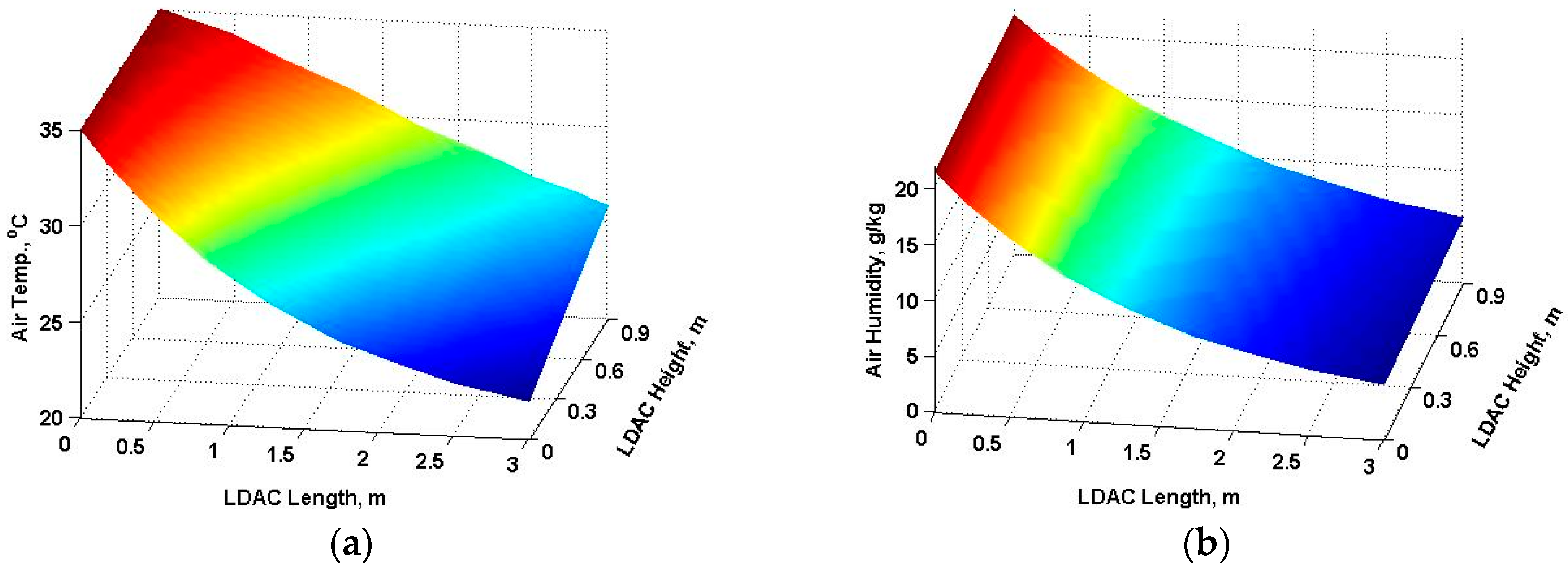
4.1. Countercurrent Flow
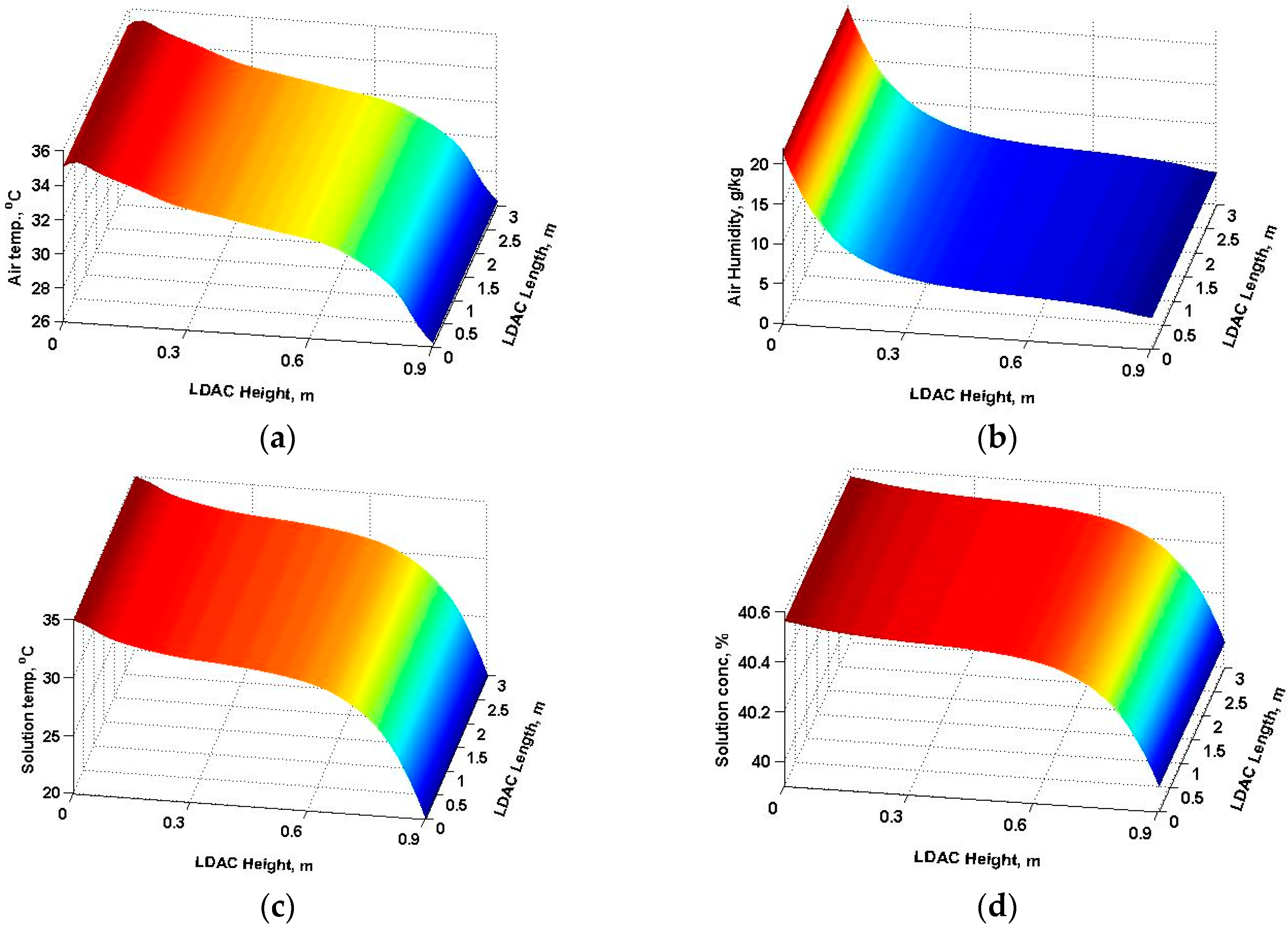
Figure 3a,b show the two-dimensional distribution of air temperature and humidity within an LDAC, respectively. The desiccant dehumidifies and cools as the air flows from left to right, when it is heated and diluted by dehumidification from the bottom to the top along the flow direction. Air temperature decreases in a uniform pattern along the entire length of the exchanger, while air humidity significantly decreases till LDAC height is 0.3 m and thereafter the air humidity remains nearly constant. At z = 0.3 m air outlet, the air temperature is lowest (26 °C) at the top compared to 35 °C at the bottom and humidity is 4% (3.95 g·kg−1) compared to 21% (21.443 g·kg−1) at the bottom since the contact is the strongest and the desiccant is the coolest there. Heat exchange is therefore enough to neglect temperature transport due to an airflow rate of 15 kg/s. The variation of the air temperature and humidity along the length of the exchanger occurs when the phase change energy is released during the moisture transfer process and increases the desiccant solution temperature, which in turn decreases the difference between temperature and vapor pressure of the air and desiccant solution; thus the driving force for moisture transfer significantly decreases, starting from LDAC height = 0.3 m [47,48,49]. At x = 0.9 m desiccant outlet, the desiccant concentration on the left is lowest (40.6%), while the temperature is higher (36 °C) since air humidity is not only the driving force of mass transfer and is basically larger there. In addition, more moisture is transported from the air to the desiccant, because the desiccant concentration is the lowest and its temperature is higher (36 °C) after vaporized latent heat is discharged while mass transfer process is as shown in Figure 3c,d. Hence, it can be seen that the air temperature, solution temperature and solution concentration have an obvious positive effect on the moisture transfer effectiveness, while the air humidity has an obvious negative effect on the moisture transfer effectiveness.

4.2. Cross-Flow

Figure 4a,b show the two-dimensional distribution of air temperature and humidity within an LDAC, respectively. The air is dehumidified and cooled along the flow direction from left side to right, when desiccant is sprayed and gets diluted along the flow direction from top to the bottom. At the air outlet (z = 0.3 m), the temperature of the air at the top is the lowest, at 25 °C, compared to 36 °C at the bottom. The humidity ratio is only 5.85% (27.74 g·kg−1) compared to 21% (21.443 g·kg−1) at the bottom as it comes in contact with the strongest and coolest desiccant there. This results in the temperature dropping, which is higher than that of the counter flow. At z = 0.9 m desiccant outlet, the desiccant concentration on the left is lowest (39.55%) and the temperature is higher (32.2 °C) since the air humidity, the driving force of the mass transfer, is basically larger there. In addition, more moisture is transported from the air to the desiccant, resulting in the lowest desiccant concentration, and a higher desiccant temperature (32.2 °C) after vaporized latent heat is discharged. The mass transfer process is as shown in Figure 4c,d. Hence, it can be seen that the solution concentration has an obvious positive effect on the moisture transfer effectiveness, while the air humidity, air temperature and solution temperature have obvious negative effects on the moisture transfer effectiveness.

5. Conclusions

This study presents an air-side heating source desiccant solution dehumidification model. We modeled two-dimensional distributions of air temperatures, air humidity, desiccant solution temperature and desiccant solution concentration, and investigated their sensitivities to xyz direction of LDAC height and length. The air and temperatures and desiccant-solution concentrations profiled by using the NTU-Le simulation model can microscopically predict dynamic flow conditions within the dehumidifier.
Design variables were found to have the greatest impact on the counter flow dehumidification performance; air temperature, solution temperature and solution concentration. It was found that increasing the desiccant solution temperature decreased the temperature of the air and desiccant solution. The desiccant solution temperature has been found to have a critical value for the performance of the dehumidification process at 26 °C. The absorber efficiency increased with an increase in desiccant inlet temperature, while it was slightly affected by the air inlet temperature and humidity ratio and desiccant inlet concentration. High system efficiency can be achieved under humid conditions (<21.443 g·kg−1), making it ideal for buildings in hot and humid regions.
Operating variables were found to have the greatest impact on the cross-flow dehumidifier performance. The conclusions from the analytical results can be summarized as follows: The LDAC height is decreased with decrease of both air inlet temperature and desiccant solution temperature, while it increases with increase in LDAC length. The dehumidifier humidity ratio (<27.74 g·kg−1) increases with the increase of desiccant solution temperature, while it decreases with the increase of air inlet temperature. Increasing air inlet temperature and desiccant solution temperature results in higher LDAC length, however, low exit humidity ratio is obtained at lower inlet desiccant concentration. The exit desiccant solution concentration remains unaffected by changing different operating parameters.
When comparing the humidity ratio drop between the cross-flow and counterflow dehumidifier, the counterflow exchangers have higher moisture transfer performance than cross-flow exchangers.

Acknowledgments

The authors would like to acknowledge the support from Multiflow Technology and the Bureau of Energy with contract number 104-E0711 in Taiwan. Thanks also for the editing service by Tim Xu, a researcher of the Lawrence Berkeley National Laboratory, USA.

Author Contributions

Shih-Cheng Hu and Archy Wang conceived and designed the experiments; Yi-Shiung Chiu performed the experiments; Angus Shiue and Yi-Shiung Chiu analyzed the data; Jacky Chen contributed reagents/materials/analysis tools; Angus Shiue wrote the paper.

Conflicts of Interest

The authors declare no conflict of interest.

Nomenclature

Aheat and mass transfer area (m2)
cp,mspecific heat of humid air (J·kg−1·K−1)
Htotal height of dehumidifier (m)
H ˙ dimensionless enthalpy (dimensionless)
hheight of dehumidifier (m)
heenthalpy(kJ·kg−1)
Llength (m)
LeLewis number (dimensionless)
M ˙ dimensionless mass flow rate (dimensionless)
m ˙ mass flow rate(kg·h−1)
NTUmdimensionless number of mass transfer unit (dimensionless)
rvaporization latent heat (kJ·kg−1)
ttime (s)
vair velocity (m·s−1)
W ˙ dimensionless humidity ratio (dimensionless)
Xdesiccant solution concentration (kgLiCl·kgsolution−1)
X ˙ dimensionless desiccant solution concentration (dimensionless)
zpacking height (m)
Greek symbols
αheat transfer coefficient(W·m−2·°C−1)
αmMass transfer coefficient(m·s−1)
ωhumidity ratio (g·kg−1)
ξ water concentration in liquid desiccant (%)
Subscripts
aair
eair in equilibrium with solution desiccant
iinitial condition
ooriginal condition
ssolution desiccant

References

  1. Feyka, S.; Vafai, K. An investigation of a falling film desiccant dehumidification/regeneration cooling system. Heat Transf. Eng. 2007, 28, 163–172. [Google Scholar] [CrossRef]
  2. Jain, S.; Bansal, P.K. Performance analysis of liquid desiccant dehumidification systems. Int. J. Refrig. 2007, 30, 861–872. [Google Scholar] [CrossRef]
  3. Oberg, V.; Goswami, D.Y. Experimental study of the heat and mass transfer in a packed bed liquid desiccant air dehumidifier. J. Sol. Energy Eng. Trans. ASME 1998, 120, 289–297. [Google Scholar] [CrossRef]
  4. Miao, R.S. Study of Alternative Liquid Absorbents Using a Thermodynamic Model and a Combined Physico-Optical Method. Ph.D. Thesis, Department of Mechanical Engineering, University of Illinois at Chicago, Chicago, IL, USA, 1997. [Google Scholar]
  5. Waugaman, D.G.; Kini, A.; Kettleborough, C.F. A review of desiccant cooling systems. J. Energy Resour. Technol.-Trans. ASME 1993, 115, 1–8. [Google Scholar] [CrossRef]
  6. Jain, S.; Dhar, P.L.; Kaushik, S.C. Evaluation of liquid desiccant based evaporative cooling cycles for typical hot and humid climates. Heat Recovery Syst. CHP 1994, 14, 621–632. [Google Scholar] [CrossRef]
  7. Kessling, W.; Laevemann, E.; Kapfhammer, C. Energy storage for desiccant cooling systems component development. Sol. Energy 1998, 64, 209–221. [Google Scholar] [CrossRef]
  8. Liu, X.H.; Zhang, Y.; Qu, K.Y.; Jiang, Y. Experimental study on mass transfer performances of cross flow dehumidifier using liquid desiccant. Energy Convers. Manag. 2006, 47, 2682–2692. [Google Scholar] [CrossRef]
  9. Liu, X.H.; Jiang, Y.; Chang, X.M.; Yi, X.Q. Experimental investigation of the heat and mass transfer between air and liquid desiccant in a cross-flow regenerator. Renew. Energy 2007, 32, 1623–1636. [Google Scholar] [CrossRef]
  10. Fumo, N.; Goswami, D.Y. Study of an aqueous lithium chloride desiccant system: Air dehumidification and desiccant regeneration. Sol. Energy 2002, 72, 351–361. [Google Scholar] [CrossRef]
  11. Gommed, K.; Grossman, G. Experimental investigation of a liquid desiccant system for solar cooling and dehumidification. Sol. Energy 2007, 81, 131–138. [Google Scholar] [CrossRef]
  12. Zhang, L.; Hihara, E.; Matsuoka, F.; Dang, C. Experimental analysis of mass transfer in adiabatic structured packing dehumidifier/regenerator with liquid desiccant. Int. J. Heat Mass Transf. 2010, 53, 2856–2863. [Google Scholar] [CrossRef]
  13. Mohammad, A.T.; Mat, S.B.; Sulaiman, M.Y.; Sopian, K.; Al-Abidi, A.A. A Statistical Analysis of a Liquid Desiccant Dehumidifier/Regenerator in an Air Conditioning System. Int. J. Therm. Environ. Eng. 2013, 5, 41–50. [Google Scholar]
  14. Bassuoni, M.M. An experimental study of structured packing dehumidifier/regenerator operating with liquid desiccant. Energy 2011, 36, 2628–2638. [Google Scholar] [CrossRef]
  15. Park, J.Y.; Jeong, J.W. A simplified model for predicting dehumidification effectiveness of a liquid desiccant system. In Proceedings of the AEI 2013: Building Solutions for Architectural Engineering, State College, PA, USA, 3–5 April 2013; pp. 516–523.
  16. Babakhani, D. Analytical approach based on a mathematical model of an air dehumidification process. Br. J. Chem. Eng. 2013, 30, 793–799. [Google Scholar] [CrossRef]
  17. Wassan, M.A.; Habib, K.; Hassan, S. Mathematical Modelling and Simulation of the Dehumidifier for the Tropical Region of Malaysia. In Proceedings of the IEEE Engineering and Industrial Applications Colloquium (BEIAC), Langkawi, Malaysia, 7–9 April 2013; pp. 795–800.
  18. Rahimi, A.; Babakhani, D. Mathematical modeling of a packed-bed air dehumidifier: The impact of empirical correlations. J. Pet. Sci. Eng. 2013, 108, 222–229. [Google Scholar] [CrossRef]
  19. Onda, K.; Takeuchi, H.; Okumoto, Y. Mass transfer coefficients between gas and liquid phases in packed columns. J. Chem. Eng. Jpn. 1968, 1, 56–62. [Google Scholar] [CrossRef]
  20. Rocha, J.A.; Bravo, J.L.; Fair, J.R. Distillation columns containing structured packings: A comprehensive model for their performance. 2. Mass-transfer model. Ind. Eng. Chem. Res. 1996, 35, 1660–1667. [Google Scholar] [CrossRef]
  21. Treybal, R.E. Mass Transfer Operations; McGraw-Hill: New York, NY, USA, 1981. [Google Scholar]
  22. Chung, T.W.; Ghosh, T.K.; Hines, A.L. Comparison between Random and Structured Packings for Dehumidification of Air by Lithium Chloride Solutions in a Packed Column and Their Heat and Mass Transfer Correlations. Ind. Eng. Chem. Res. 1996, 35, 192–198. [Google Scholar] [CrossRef]
  23. Kumar, R.; Asati, A.K. Simplified Mathematical Modelling of Dehumidifier and Regenerator of Liquid Desiccant System. Int. J. Curr. Eng. Technol. 2014, 4, 557–563. [Google Scholar]
  24. Niu, R.P. Modeling and Numerical Simulation of Dehumidifier Using LiCl Solution as the Liquid Desiccant. Adv. Mater. Res. 2012, 383–390, 6568–6573. [Google Scholar] [CrossRef]
  25. Bassuoni, M.M. Analytical Modeling and Performance Study of a Cross Flow Air Dehumidifier Using Liquid Desiccant. Adv. Mater. Res. 2014, 875–877, 1205–1213. [Google Scholar] [CrossRef]
  26. Bassuoni, M.M. A simple analytical method to estimate all exit parameters of a cross-flow air dehumidifier using liquid desiccant. J. Adv. Res. 2014, 5, 175–182. [Google Scholar] [CrossRef] [PubMed]
  27. Lu, H.; Lu, L.; Luo, Y.M.; Qi, R.H. Investigation on the dynamic characteristics of the counter-current flow for liquid desiccant dehumidification. Energy 2016, 101, 229–238. [Google Scholar] [CrossRef]
  28. Abdel-Salam, M.R.H.; Fauchoux, M.; Ge, G.; Besant, R.W.; Simonson, C.J. Expected energy and economic benefits, and environmental impacts for liquid-to-air membrane energy exchangers (LAMEEs) in HVAC systems: A review. Appl. Energy 2014, 127, 202–218. [Google Scholar] [CrossRef]
  29. Ge, G.; Abdel-Salam, M.R.H.; Besant, R.W.; Simonson, C.J. Research and applications of liquid-to-air membrane energy exchangers in building HVAC systems at university of Saskatchewan: A review. Renew. Sustain. Energy Rev. 2013, 26, 464–479. [Google Scholar] [CrossRef]
  30. Bergero, S.; Chiari, A. Experimental and theoretical analysis of air humidification/dehumidification processes using hydrophobic capillary contactors. Appl. Therm. Eng. 2001, 21, 1119–1135. [Google Scholar] [CrossRef]
  31. Zhang, L.Z. An analytical solution to heat and mass transfer in hollow fiber membrane contactors for liquid desiccant air dehumidification. Trans. ASME J. Heat Transf. 2011, 133, 1–8. [Google Scholar] [CrossRef]
  32. Abdel-Salam, M.R.H.; Ge, G.; Fauchoux, M.; Besant, R.W.; Simonson, C.J. State-of-the-art in liquid-to-air membrane energy exchangers (LAMEEs): A comprehensive review. Renew. Sustain. Energy Rev. 2014, 39, 700–728. [Google Scholar] [CrossRef]
  33. Abdel-Salam, M.R.H.; Besant, R.W.; Simonson, C.J. Sensitivity of the performance of a flat-plate liquid-to-air membrane energy exchanger (LAMEE) to the air and solution channel widths and flow maldistribution. Int. J. Heat Mass Transf. 2015, 84, 1082–1100. [Google Scholar] [CrossRef]
  34. Ge, G.; Abdel-Salam, A.; Abdel-Salam, M.R.; Besant, R.; Simonson, C. Heat and mass transfer performance comparison between a direct-contact liquid desiccant packed bed and a liquid-to-air membrane energy exchanger for air dehumidification. Sci. Technol. Built Environ. 2016. [Google Scholar] [CrossRef]
  35. Ruivo, C.R.; Costa, J.J.; Figueiredo, A.R. On the validity of lumped capacitance approaches for the numerical prediction of heat and mass transfer in desiccant airflow systems. Int. J. Therm. Sci. 2008, 47, 282–292. [Google Scholar] [CrossRef]
  36. Mandegari, M.A.; Pahlavanzadeh, H.; Farzad, S. Energy approach analysis of desiccant wheel operation. Energy Syst. 2014, 5, 551–569. [Google Scholar] [CrossRef]
  37. Xu, X.Y.; Paschke, S.; Repke, J.U.; Yuan, J.Q.; Wozny, G. Computational approach to characterize the mass transfer between the counter-current gas-liquid flow. Chem. Eng. Technol. 2009, 32, 1227–1235. [Google Scholar] [CrossRef]
  38. Peng, S.W.; Pan, Z.M. Heat and mass transfer in liquid desiccant air-conditioning process at low flow conditions. Commun. Nonlinear Sci. Numer. Simul. 2009, 14, 3599–3607. [Google Scholar] [CrossRef]
  39. Pesaran, A.A. Heat and Mass Transfer Analysis of a Desiccant Dehumidifier Matrix; Solar Energy Research Institute: Golden, CO, USA, 1986. [Google Scholar]
  40. Khan, A.Y.; Ball, H.D. Development of a generalized model for performance evaluation of packed-type liquid sorbent dehumidifiers and regenerators. ASHRAE Trans. 1992, 98, 525–533. [Google Scholar]
  41. Li, C.Z.; Jiang, Y.; Qu, K.Y. Analytical solution of adiabatic heat and mass transfer process in packed-type liquid desiccant equipment and its application. Sol. Energy 2006, 80, 1509–1516. [Google Scholar]
  42. Diaz, G. Numerical investigation of transient heat and mass transfer in a parallel-flow liquid-desiccant absorber. Heat Mass Transf. 2010, 46, 1335–1344. [Google Scholar] [CrossRef]
  43. Hammad, M.M.; El-Ghanam, R.I.; Sakr, R.Y.; Ayad, S.S. Theoretical study for compact liquid desiccant dehumidifier/regenerator system. In Proceedings of the Al/Azhar Engineering Tenth International Conference, Cairo, Egypt, 24–26 December 2008; Volume 3, pp. 352–378.
  44. Lin, C.; Qun, C.; Zhen, L.; Yuan, G.Z. Moisture transfer resistance method for liquid desiccant dehumidification analysis and optimization. Chin. Sci. Bull. 2010, 55, 1445–1453. [Google Scholar]
  45. Cizniar, M.; Salhi, D.; Fikar, M.; Latif, M.A. A Matlab package for orthogonal collocations on the finite elements in dynamic optimization. In Proceedings of the 15th International Conference Process Control, Strbské Pleso, Slovakia, 7–10 June 2005.
  46. Villadsen, J.V.; Stewart, W.E. Solution of boundary-value problems by orthogonal collocation. Chem. Eng. Sci. 1967, 22, 1483–1501. [Google Scholar] [CrossRef]
  47. Abdel-Salam, M.R.H.; Besant, R.W.; Simonson, C.J. Design and testing of a novel 3-fluid liquid-to-air membrane energy exchanger (3-fluid LAMEE). Int. J. Heat Mass Transf. 2016, 92, 312–329. [Google Scholar] [CrossRef]
  48. Abdel-Salam, M.R.H.; Besant, R.W.; Simonson, C.J. Performance testing of a novel 3-fluid liquid-to-air membrane energy exchanger (3-fluid LAMEE) under desiccant solution regeneration operating conditions. Int. J. Heat Mass Transf. 2016, 95, 773–786. [Google Scholar] [CrossRef]
  49. Abdel-Salam, M.R.H.; Ge, G.; Besant, R.; Simonson, C. Experimental study of effects of phase change energy and operating parameters on performances of two-fluid and three-fluid liquid-to-air membrane energy exchangers. ASHRAE Trans. 2016, 122, 134–145. [Google Scholar]
Figure 1. A control volume of the counter-flow air dehumidification packed tower.
Sustainability 08 01264 g001
Figure 2. A control volume on the cross-flow air dehumidification packed tower.
Sustainability 08 01264 g002
Figure 3. Two-dimensional distribution of counter flow dehumidifier (a) air temperature; (b) air humidity; (c) solution temperature; and (d) solution concentration.
Sustainability 08 01264 g003
Figure 4. Parametric distribution of cross-flow dehumidifier (a) air temperature; (b) air humidity; (c) desiccant temperature; and (d) desiccant concentration.
Sustainability 08 01264 g004aSustainability 08 01264 g004b
Table 1. Properties of LiCl solution (27 °C and 35% mass concentration) and operating parameters.
ρ (kg·m−3)μ (kg·m−1·s−1)σ (N·m−1)θw (°)
LiCl solution11800.003420.089165
inlet air temperature (°C)27
inlet air humidity ratio (g·kg−1)18
air mass flow rate (kg·h−1)25
desiccant solution mass flow rate (kg·h−1)10
inlet desiccant solution equivalent concentration (%)40
Table 2. Design parameters of the dehumidifier.
NTU1–4
NTUm0.37–0.67
bed dimensions1.35 m (L) × 1 m (W) × 2.3 m (H)
materialFiberglass reinforced plastic
geometrycuboid
porosity of packing35%

