Article

Life-Cycle Assessment of Seismic Retrofit Strategies Applied to Existing Building Structures

Department of Structures for Engineering and Architecture, University of Naples Federico II, Via Claudio 21, 80125 Naples, Italy
*
Author to whom correspondence should be addressed.
Sustainability 2016, 8(12), 1275; https://doi.org/10.3390/su8121275
Submission received: 4 October 2016 / Revised: 10 November 2016 / Accepted: 30 November 2016 / Published: 8 December 2016
(This article belongs to the Section Sustainable Engineering and Science)

Abstract

:
In the last few years, the renovation and refurbishment of existing buildings have become the main activities of the construction industry. In particular, many studies have recently focused on the mechanical and energy performances of existing retrofitted/refurbished facilities, while some research has addressed the environmental effects of such operations. The present study aims to assess the environmental impact of some retrofit interventions on an existing reinforced concrete (RC) building. Once the structural requirements have been satisfied and the environmental effects of these retrofit solutions defined, the final purpose of this study is to identify the most environmentally sustainable retrofit strategy. The environmental impact of the structural retrofit options is assessed using a life-cycle assessment (LCA). This paper sets out a systematic approach that can be adopted when choosing the best structural retrofit option in terms of sustainability performance. The final aim of the study is to also provide a tool for researchers and practitioners that reflects a deep understanding of the sustainability aspects of retrofit operations and can be used for future researches or practical activities.

1. Introduction

In the last few years, several studies have focused on the assessment of global environmental impacts in both developed and developing countries. Global warming, and its different potential effects on the planet, is a consequence of the long-term accumulation of greenhouse gases (CO2, CH4, N2O, etc.) in the higher layer of the atmosphere [1]. Due to this phenomenon, it is important for future generations to give priority to sustainable development in the execution of activities in all sectors, thus preventing damage to the environment.
To achieve the sustainability goal, it is necessary to adopt a multi-disciplinary approach covering a number of features such as: energy saving, better use of materials, reuse of materials and recycling, and control of emissions [2].
The construction industry has a significant global impact on the environment. In fact, in each country, this sector is one of the major users of energy and natural resources. In Europe, for example, buildings are responsible for almost 30% of national energy consumption, 40% of greenhouse gas emissions and 40% of the consumption of materials [3,4,5].
This means that it is necessary to involve the construction industry when looking to achieve sustainable development.
Some methodological frameworks analyze single or multiple aspects of environmental scenarios that are related to construction activities [6]. These frameworks are contained in national/international standards and legislation, and can be mandatory or voluntary [7].
The life-cycle assessment (LCA) is a decision-making support tool within the building sector, because it provides an account of the materials and energy used in a product and assesses the related environmental impact [8].
Application of LCAs to the construction industry started two decades ago [9,10,11]. Two alternative approaches have been adopted when applying an LCA to the building sector. These are [12,13]:
  • An LCA for building materials and component combinations (bottom up).
  • An LCA of the entire construction process (top down) [14].
Jönsson et al. [15] compared the environmental impact of three flooring materials in Sweden using an LCA. Asif et al. [2] also conducted an LCA of materials used in residential constructions in Scotland, and found that concrete was responsible for over 60% of the total embodied energy. Ximenes and Grant [16], meanwhile, compared the advantages of wood and alternative building products in Australia, finding that greenhouse gas benefits occurred when the original floor and sub-floor products were replaced by timber. Wu et al. [17] conducted an LCA of several types of concrete and steel that are generally used in the Chinese building industry, adopting a “green tax-based weighting” approach in the course of their research. Esin [18] used a similar approach to evaluate the environmental effects generated during the production of various building materials in Turkey. Asdrubali [19], meanwhile, investigated the environmental impact of the replacement of conventional thermal and sound insulating materials with sustainable versions. Their LCA showed significant benefits in terms of the environmental impact of all the various life-cycle phases of the building due to this substitution of materials [20].
Adalberth et al. [21] performed an LCA in 1996 of four multi-family buildings built in Sweden. The goal of the research was to investigate the different life-cycle stages of the four buildings in order to identify the phase with the greatest environmental impact. The stages considered in the research were: manufacturing, transport, erection, use, renovation, demolition and removal [20]. The authors discovered that the use phase accounted for about 70%–90% of the total environmental impact of the buildings.
On the other hand, Xing et al. [22] performed a comparative LCA involving a steel and reinforced concrete (RC) office building with different floor areas. Pajchrowski et al. [23] in turn assessed the environmental impact of four equivalent buildings made of two different building materials (wood and masonry) throughout their entire life-cycle. Guggemos and Horvath [24], meanwhile, compared the environmental effects of the construction phase of steel- and concrete-framed office buildings using an LCA. The results showed that the concrete-framed building had higher emissions and energy consumption due to its longer installation process. Kofoworola and Gheewala [25] conducted an LCA of an RC office building in Thailand. They found that steel and concrete were the materials with the greatest environmental impact, and their use-phase accounted for 52% of the energy consumption of the total life-cycle. Blengini [26] performed an LCA of a building that was demolished by controlled blasting. The demolition phase and its recycling potential were both included in this study. The research showed that building waste recycling has a low environmental impact from an energy and environmental point of view, but is not profitable in economic terms. Pushkar [27] evaluated the environmental damage form three flat roof technologies typically used in Israel, which are: concrete, ribbed slab with concrete blocks, and ribbed slab with autoclaved aerated blocks.
Nevertheless, there are very few studies that evaluate the environmental impact of the retrofitting of buildings. Usually, retrofit studies have focused on the mechanical, functional and energy performances of retrofitted structures. Ardente et al. [28] presented a study in which they compared six public buildings located in different countries where retrofit actions had been implemented. The authors concluded that the replacement of lighting and glazing components had important energy benefits, but the most significant advantages in terms of energy savings and the reduction of CO2 emissions were due to the improvement of thermal insulation. Strategies to reduce buildings’ heating and cooling demands were also investigated by Asadi et al. [29], Ascione et al. [30], Biekšaa et al. [31], Xing et al. [32], and Užšilaitytea and Martinaitis [33]. The environmental impact of some strengthening solutions, such as the steel jacketing of structural members and the application of fibre-reinforced polymer (FRP) sheets, has been investigated by Moliner et al. [34], Zhang et al. [35] and Das [36]. Moreover, Rodrigues and Freire [37], Perini [38], and Allacker [39] performed life-cycle (LC) analyses to evaluate the impact of different structural options such as flat roofs, wooden floor, and the integration of green roofs in existing buildings.
The decision-making process in a retrofit operation should be regarded as a multi-objective, multi-criteria optimization problem [14,40,41,42]. Indeed, as reported in Juan et al. [43], the best option should be chosen by considering several matters such as energy consumption, economics, technical and environmental factors, relevant regulations, and social effects, while the overall process of a building retrofit could be divided into three main steps. The first step consists of a structural analysis of a facility to assess capacity and identify the strengthening solution aimed at extending its lifetime. In the second step, these retrofit actions should be evaluated using appropriate criteria (quantitatively expressed by proper indicators), with consideration given to financial, environmental, social and structural factors. Finally, the third step consists of the identification of the optimal retrofit solution. If this approach is adopted, both sustainability and structural requirements are implemented in the design stage of the retrofit.
Generally, designers take only some parameters into account in the decision-making process. These are:
  • Costs.
  • Structural performance.
  • Speed of the installation process.
  • Suspension time.
  • Feasibility of the maintenance processes.
Designers very rarely consider environmental effects in the decision-making process due to the difficulty of assessing some factors.
Within this context, and according to the approach taken by Juan et al. and Menna et al. [14,43], the purpose of this paper is to evaluate different strengthening solutions applied to an RC building located in Italy. In particular, the study analyzes and compares the environmental performances of four retrofit strategies, all of which have an equivalent strengthening effect. These strengthening solutions are: the application of FRP sheets to the surface of the structural elements; the RC jacketing of columns and the application of FRP sheets to the surface of beams and joints; the installation of RC shear walls; and the base isolation of the building. The environmental impact of the retrofit options is examined using an LCA, according to ISO 14040:2006 and ISO 14044:2006 [44,45].

2. LCA Methodology

The LCA considers the entire life-cycle of a product, from raw material extraction and acquisition (through energy and material production and manufacturing) to use and end-of-life disposal [44]. Through this systematic approach, the LCA has the opportunity to analyze the environmental impact of a facility during the various life-cycle stages. The LCA methodology is increasingly being applied to the construction industry in order to quantify the environmental effects of the use of energy, CO2 emissions, the use of renewable and non-renewable resources, and the emission of organic and non-organic compounds into the air, water and soil.
Given these features, an environmental impact assessment in the construction industry using an LCA could be usefully adopted for:
(a)
The development of tools and databases related to the impact of products, technologies, systems and processes.
(b)
The selection of construction products.
(c)
The evaluation of construction systems and procedures [6].
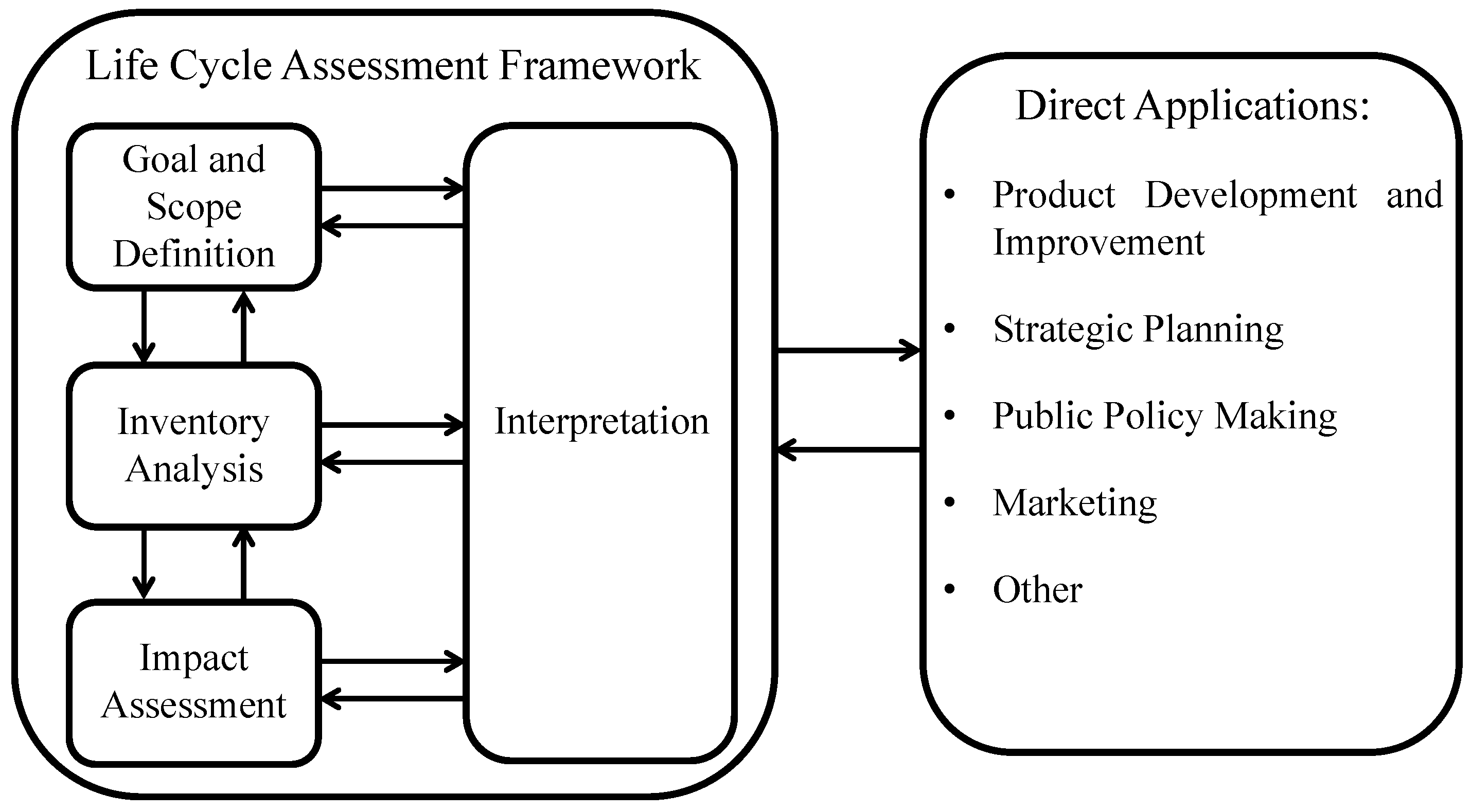
The LCA is part of ISO 14040:2006 (Environmental management—life-cycle assessment—principles and framework) [44] and ISO 14044:2006 [45] (Environmental management—life-cycle assessment—requirements and guidelines). The methodology is an iterative technique and consists of four main steps, as reported in Figure 1:
(a)
Goal and scope definition.
(b)
Inventory analysis or life-cycle inventory (LCI).
(c)
Impact assessment or life-cycle impact assessment (LCIA).
(d)
Interpretation of the results.
The goal and scope phase defines the purpose of the study, its application, the products to be used, the system boundaries and the functional unit. The functional unit is an important step that enables alternative products or services to be compared and analyzed; it is not the mere quantification of materials.
The LCI phase is a detailed description of all the environmental inflows (e.g., materials, embodied energy) and outflows (e.g., air, water and solid emissions) at each stage of the life-cycle. So, the LCA practitioner assesses emissions and the consumption of resources in each phase of the product’s life-cycle (from “cradle to grave”). Usually in this phase, a work flow diagram of the product or process’s entire life-cycle is constructed.
The LCIA phase quantifies all the environmental effects and the resources used. The results of the previous phase are used in the LCIA to evaluate the corresponding environmental impact. According to ISO 14042 [46], LCI results are classified into impact categories (such as climate change, toxicological stress, noise, land use) and, in some cases, in an aggregated manner (such as years of human life lost due to climate change, carcinogenic effects, noise), each with a category indicator.
There are two assessment methods:
(a)
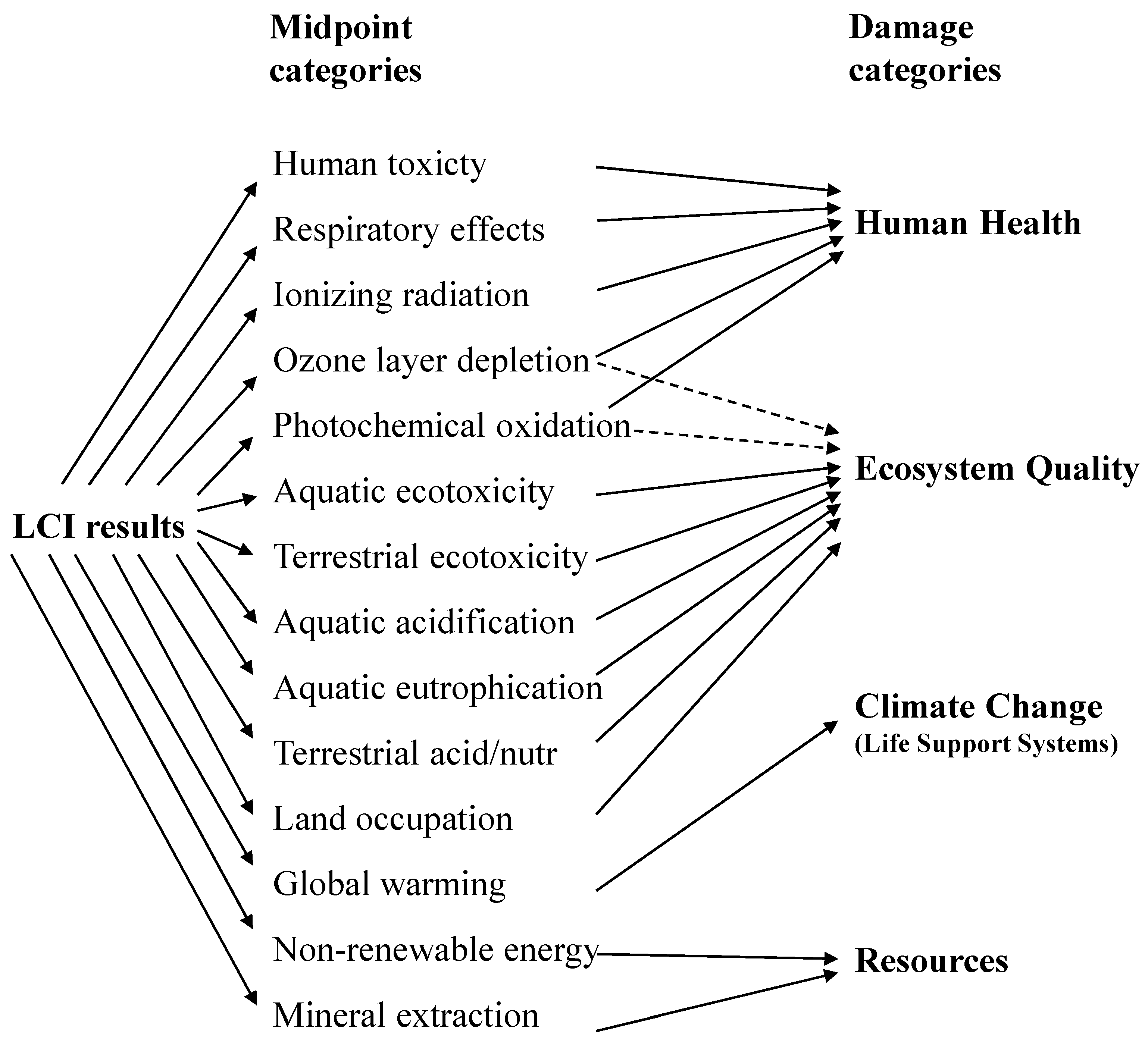
Classical impact assessment (e.g., Centre of Environmental Sciene – Leiden University (CML) [47] and Environmental Design of Industrial Products (EDIP) [48]), which collects LCI results in so-called midpoint categories. These points are located somewhere in the cause-effect chain between LCI results and the endpoint and limit uncertainties.
(b)
Damage-oriented approaches such as Eco-indicator 99 [49] or Environmental Priority Strategies EPS [50], which collect LCI results in endpoint categories, sometimes with high uncertainties.
In the last step, namely the interpretation of the results, the life-cycle phases and the products with the greatest enviromental impact are identified.
Overall, life-cycle interpretations occur at every stage in an LCA. A practitioner will thus be able to determine the best solution after the LCI phase if two product alternatives are compared.
The LCA is a relative approach, which depends on the functional unit chosen. Indeed, the functional unit influences all the inputs and outputs in the LCI stage and, consequently, the results of the LCIA.
The depth of detail and the amount of time required for an LCA may vary depending on the accuracy and goal and scope definition. Effectively, there is no a single method for conducting an LCA.
Usually, economic and social factors are beyond the scope of the LCA, but they can be combined with this approach using specific tools for a more detailed analysis. Moreover, there are many other applications to which the LCA can be applied, such as life-cycle management (LCM) [51], social life-cycle assessment (SLCA) [52], life-cycle thinking (LCT) [53], life-cycle costing (LCC) [54], the risk analysis of facilities, the hazard risk assessment of compounds, and, above all, the environmental impact assessment (EIA) [55].
In conclusion, there is no a single way to develop an LCA within the decision-making context. LCA practitioners thus have to decide, case by case, by considering several factors such as products, strategy, systems and available tools.

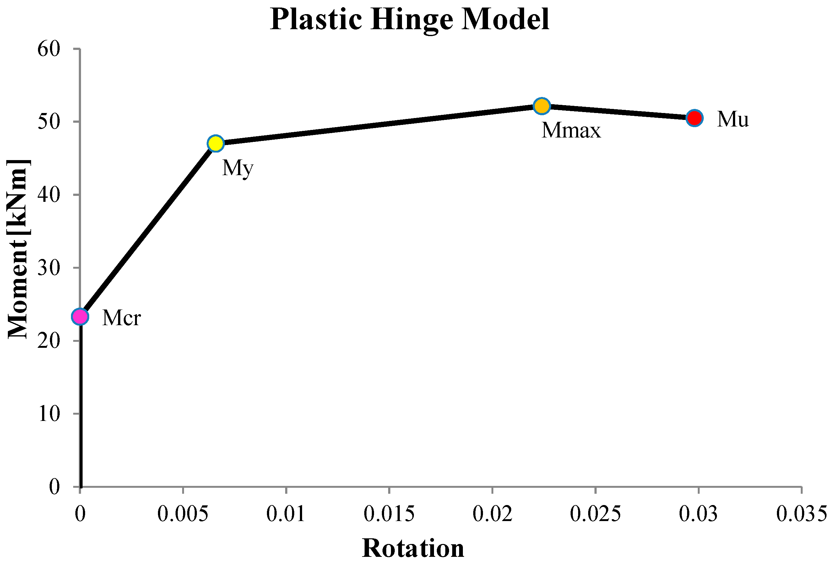
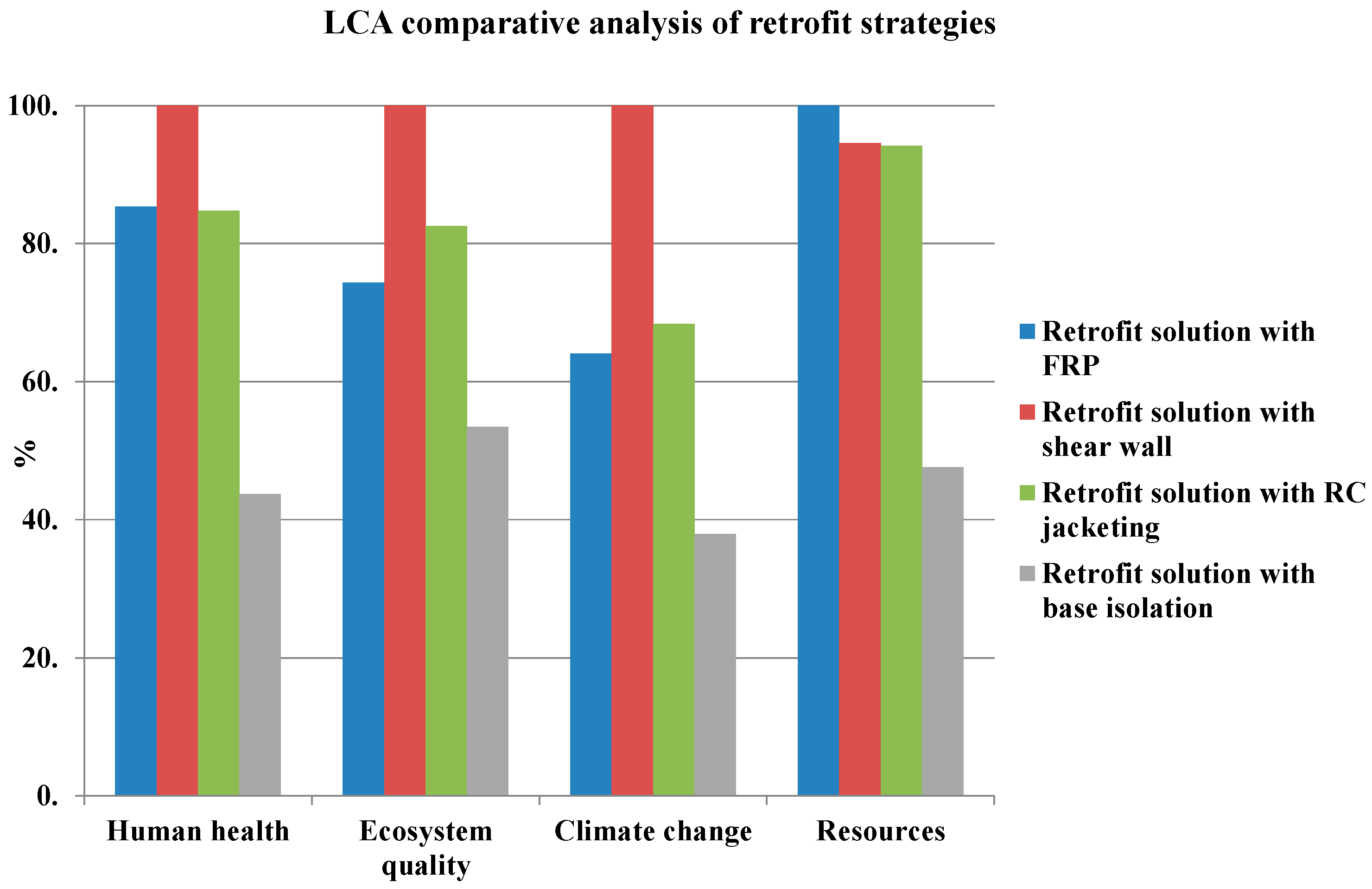
3. Retrofit Strategies

In a very seismic territory such as Italy, the attention of designers in the last few decades has principally been focused on seismic effects, with the aim being to guarantee an adequate structural performance with the purpose of safeguarding human life. In fact, most existing structures have been designed and built with reference to old building codes, with limited seismic provision. Accordingly, strengthening interventions are necessary to improve the structural capacity of structures in the face of seismic events. Generally, retrofit actions are based on four main strategies: (a) an increase of structural strength and stiffness; (b) an increase of the global energy dissipation capacity; (c) an increase of both structural strength and deformation capacity; and (d) a reduction of the seismic demand.
The selection criteria for strengthening interventions are mainly based on their effectiveness, application time and cost; the environmental impact of the interventions is still a secondary criterion in the final decision. In this research, the LCA methodology described is implemented in a case study of the sustainability of four retrofit options in an existing RC building. In particular, the aim of the study is to compare the environmental impact of materials and processes related to the four options set out above, with a cradle-to-gate system boundary. This system boundary allows a partial assessment that takes into account environmental impacts from the resource extraction to the installation phase.

Design of the Seismic Strengthening Interventions

A building that is assumed to be located in the city of Naples has been chosen as the case study for implementing the procedure illustrated in the previous sections of this paper. The building is an academic example of a typical Italian facility built in the 70s with the old building code and without any seismic prevision. The building has an approximate rectangular shape in terms of the plane configuration and three storeys. The structure is made up of RC frames in two directions and two staircases. The floor plan of the building has dimensions of 48.10 m in one direction and 18.10 m in the other, with a total area of about 870 m2 (Figure 2). The foundation system is composed of RC footings and connection beams framed in two orthogonal directions. The total height of the building is 10.1 m and it consists of three floors with a storey height of 3.2 m, except for the first floor, which is 3.7 m. The following mechanical properties have been assumed for the materials: the concrete compressive strength fcm = 15 MPa; and the steel tensile strength fym = 220 MPa. The cast-in-situ RC slabs are 24 cm high and the joist beams are oriented in one direction.
The geometrical proprieties of the elements are listed in Table 1.
Table 2 lists the first three vibration modes of the structure and the participating mass of each mode.
The non-linear building response was simulated with finite element software (SAP2000; Computers and Structures, Inc., Walnut Creek, CA, USA) using lumped plasticity models of the beams and columns (four hinges for each structural member: top and bottom for both directions). The column and beam plastic hinge models are calculated according to the European Code UNI-EN 1998-3:2005 [56], as shown in Figure 3.
Non-linear static analyses have been carried out for the two plan directions of the structure (X and Y directions) up to its global mechanism. A bilinearization procedure has been performed according to the N2 approach (where N stand for non-linear and 2 for two mathematical models) for each step of the pushover curve [57]. Accordingly, a PGA (Peak Ground Acceleration) value is derived for each step of the curve as the demand intensity that would induce that particular structural response. A severe earthquake with a return period of 475 years has been assumed to be the structural demand, according to the Italian National Building Code [58]. The PGA demand value depends on the site hazard and in the case study is 0.168 g.
The achievement of the first failure mechanism due to stress of a structural member identifies the PGA capacity of the structure, and the ratio between the capacity and the demand in terms of the PGA has been defined as the safety level. In the case study, the non-linear static analyses have shown a very low value of the ratio between seismic capacity and seismic demand for the structure in the original configuration, and retrofit interventions are necessaries. The aim of these interventions is to increase the seismic capacity of the structural members in order to have the first failure mechanism in correspondence of a PGA value higher than the PGA demand [59].
In order to carry out an analysis of the environmental impact of several strengthening strategies, the performance of the building is improved with the different retrofit options at the same safety level, meaning that the seismic capacity of the structure after the retrofit is equal to the seismic demand imposed by the Italian National Building Code [58].
The strengthening strategies aim to either increase the ductility, stiffness and strength, or all of them, of the structural elements or to reduce the seismic demand. According to these goals, the following strengthening techniques have been adopted in this case study:
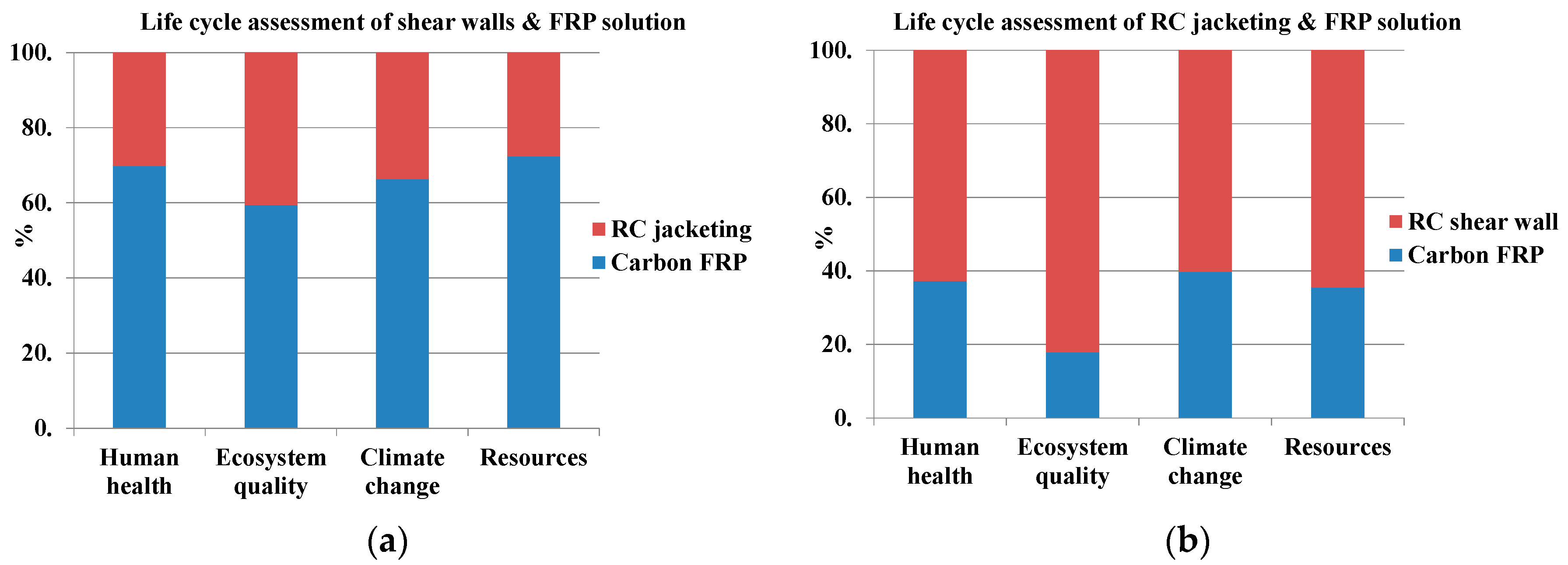
FRP-based strengthening solution (i.e., shear strengthening of the beam-column joints, columns and beams using FRP sheets to prevent brittle failure mechanisms, and the confinement of columns at the ends by means of FRP wrapping to increase the structural global ductility); this strategy aims to increase the ductility and strength of the structure.
FRP-RC jacketing-based strengthening solution (i.e., RC jacketing of columns to increase the flexural and shear capacity of the members and the shear strengthening of the beam-column joints and beams using FRP sheets. This allows a slight increase in the building’s global stiffness that is to be balanced with the local increase in shear capacity in order to prevent brittle failure mechanisms).
Insertion of RC shear wall-based strengthening solution (i.e., insertion of two shear walls in the Y direction to sustain the seismic action); this strategy aims to increase the strength and stiffness of the structure.
Base isolation (i.e., inserting a horizontally flexible and dissipative interface on the first floor of the building, thus significantly reducing the demand rather than increasing the structural capacity).
The first method consists of the application of one or more quadriaxial FRP sheets to the surface of the beam-column joint panels and uniaxial FRP sheets onto the beams and columns as shear strengthening.
The second intervention strategy aims to improve the seismic performance of the individual elements, with RC jacketing with a thickness of at least 5 cm or the application of FRP sheets as described above against shear failures. The structure increases its capacity in terms of both stiffness and ductility with these intervention strategies.
The third strategy aims to increase the stiffness of the structure by the insertion of two RC shear walls in the Y direction. Nevertheless, the insertion of the shear walls does not avoid all the brittle crises of the structural members. Quadriaxial and uniaxial FRP sheets are applied to increase the shear capacity of the joints and beams.
The fourth strategy consists of the insertion of rubber bearings and friction isolators between the first and second floors. The structure rests on these devices, which provide sufficient energy dissipation and allow significant relative displacement. The building must achieve a target period (higher than in the as-built configuration) that corresponds to the target spectral acceleration in the inelastic spectra demand. The target spectral acceleration depends on the step of the pushover curve where the first ductile failure occurs. However, the insertion of the isolation devices could not prevent all the brittle failures of the structural members, and limited FRP shear strengthening of the single elements is therefore necessary.

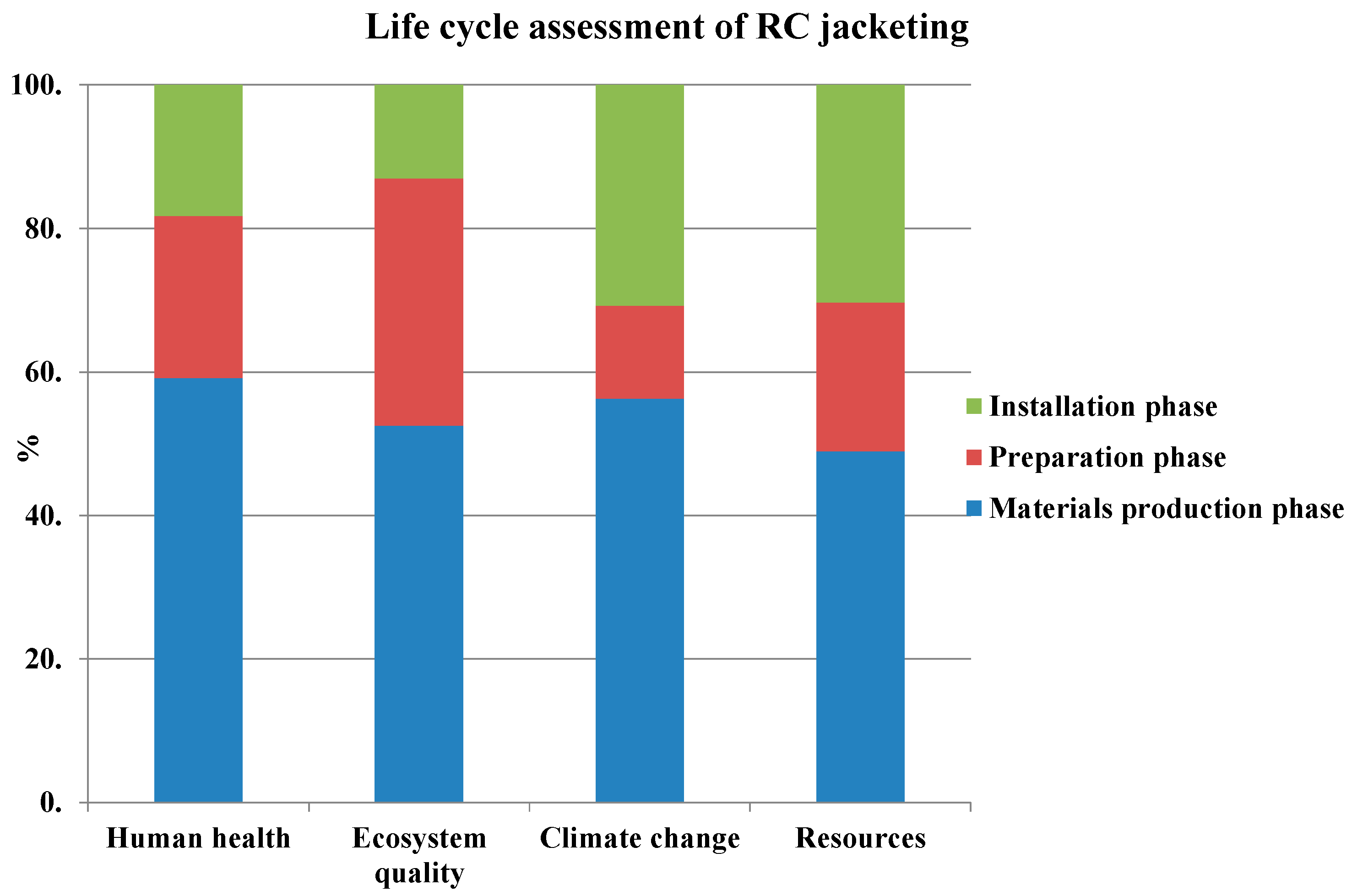
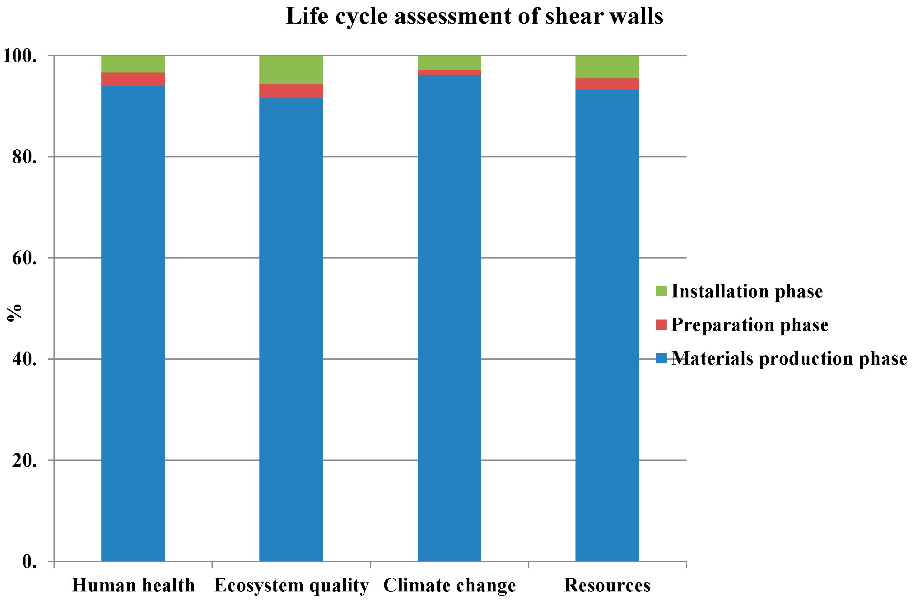
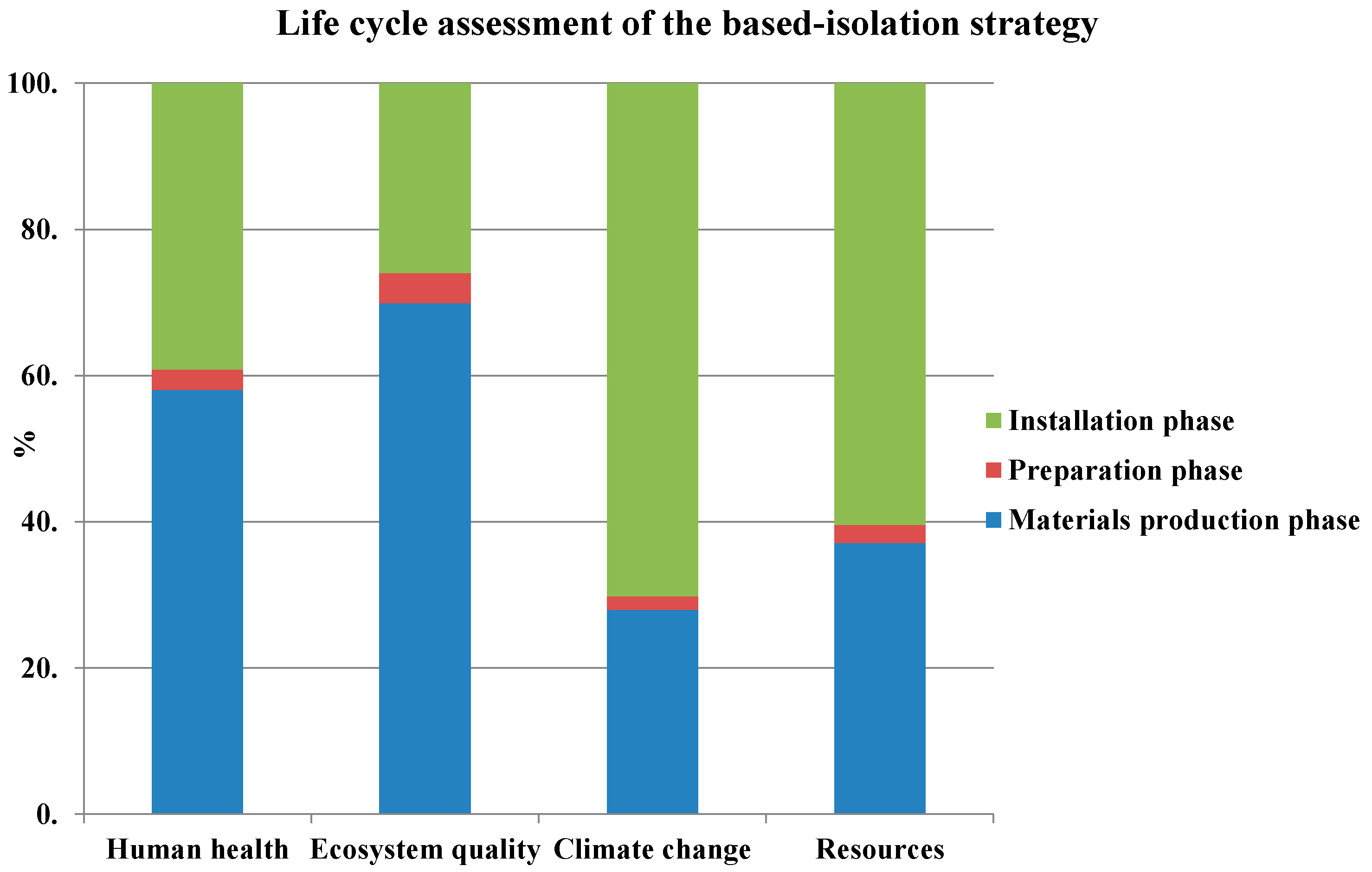
4. Life-Cycle Assessment of the Strengthening Strategies

The proposed approach, based on the LCA scheme reported in Figure 1, aims to contribute to the sustainable design of retrofit interventions in the construction sector.
The main hypothesis for this LCA comparative study of the retrofit options is that the different strengthening solutions are designed to achieve the same structural performance in terms of seismic capacity. In fact, as described above, the retrofit strategies applied to the existing structures are designed to increase the structural capacity in order to achieve the same seismic safety level.
The LCA is conducted for each investigated solution, with a cradle-to-gate system boundary, and includes the following phases: extraction and processing of raw materials, manufacturing, and installation of the strengthening system. The other life-cycle phases such as use, maintenance, end of life and transportation are not included in this application case.

4.1. Goal and Scope Definition
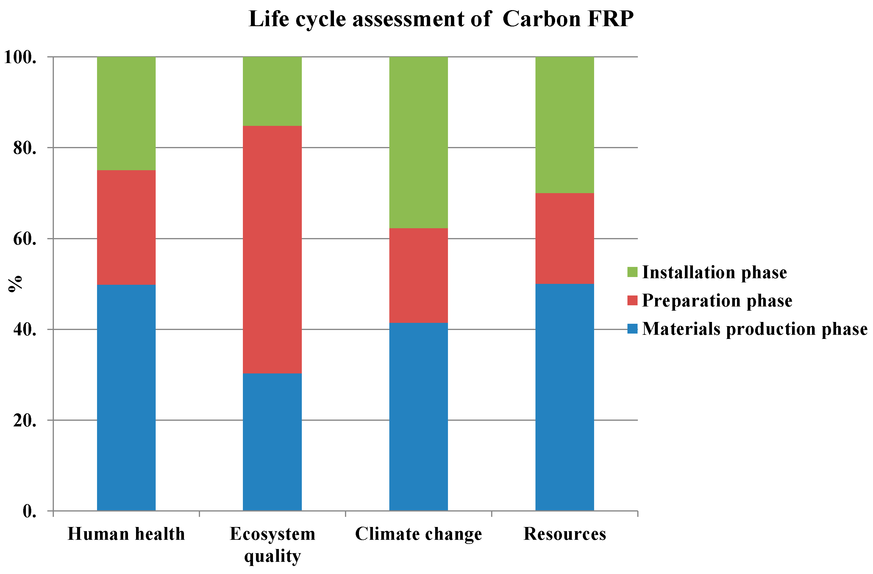
The goals and scope of this study are to separately assess the environmental impact of the structural retrofit options that are usually applied to existing RC structures. In detail, four strengthening solutions have been taken into account in order to define which strategy is more sustainable and is characterized by the lowest environmental impact.
Following the scheme of the LCA, the strengthening of the entire building, which allows that the PGA capacity is equal to the PGA related to an earthquake of 475 years, has been assumed as the functional unit for the assessment.
Finally, the system boundary adopted in this study includes the following three phases:
(a)
Materials production phase (extraction and production of the materials and construction phases).
(b)
Preparation phase (building demolition, material disposal and transport).
(c)
Installation phase (application of the technique).
For the demolition operations needed for the installation of the systems, it is assumed that the waste materials are sent to a landfill site and/or an incinerator, and that the demolition of the partitions is carried out using manual operations and electrical equipment in order to avoid both further brick damage and compromising the integrity of the wall. All the processes and materials included in the three phases in the system boundary are explained in detail in Table 3.

4.2. Inventory Analysis (LCI)

In this phase, primary data have been used to model the production of carbon FRP sheets and rubber-bearing isolators while secondary data have been retrieved from databases available in the SimaPro 7.3 LCA software package (PRé Consultants, Amersfoort, The Netherlands). SimaPro is an efficient tool (also used for the LCIA phase) that is useful for collecting sustainability data and analyzing and monitoring the sustainability performance of products/services. In the application case, secondary data taken from the Ecoinvent 2.2 database [60] have been used to assess the environmental impacts of building materials, the use of building equipment, transport operations and electricity. This is a broad environmental database that includes compositions, production processes, the disposal scenarios for most of the existing materials, industrial processes and construction materials.
The design of the retrofit interventions have been carried out according the structural requirements reported in Italian building codes, thus the amount of data related to the material and the processes involved in each strengthening option (including equipment/machinery use) are based on the design process. [59,61].
Furthermore, some assumptions have been made regarding the transport phase:
  • The distance between the construction and landfill sites is assumed to be 20 km.
  • The material-supplying site is located 5 km from the construction site.
  • The transport of the building materials from/to the construction site is assumed to be carried out by a lorry (EURO3).

4.3. Impact Assessment (LCIA)

The LCIA assesses the environmental impact of the strengthening strategies. This phase has been carried out using the Impact 2002+ approach.
The IMPACT 2002+ LCIA methodology is a combined approach that links midpoints and damage categories, as shown in Figure 4 [62]. In particular, it links life-cycle inventory result to four damage categories via 14 midpoint categories (human toxicity, respiratory effects, ionizing radiation, ozone layer depletion, photochemical oxidation, aquatic ecotoxicity, terrestrial ecotoxicity, terrestrial acidification/nutrification, aquatic acidification, aquatic eutrophication, land occupation, global warming, non-renewable energy, mineral extraction). These four categories are described as follows:
  • Climate change (CC): this evaluates substances that contribute to global warming.
  • Human health (HH): this evaluates the consequences of the release of substances that affect human beings.
  • Ecosystem quality (EQ): this evaluates the potential consequences for the health of an ecosystem.
  • Resource depletion (RD): this measures the depletion due to mineral extraction and the consumption of resources (renewable and non-renewable).
All the midpoint scores are expressed in units of a reference substance and related to the four damage categories, as listed in Table 4.
The assessed environmental effects are shown in terms of the damage categories for each life-cycle phase of the four strengthening strategies. The four damage categories have different damage units (as reported in Table 4) and need to be normalized in order to analyze the respective share of each impact to the overall damage. The impact values are divided by the maximum value achieved among the four options for each category and are plotted in percentages in order to effectively illustrate the building’s environmental performance comparison.
The first set of figures report for each strategy the contribution of different phases to that strategy. Figure 5 shows the LCIA of the carbon FRP solution. The preparation phase makes the highest contribution to ecosystem quality, while the materials and production phase has the greatest impact on human health, climate change and resources.
The environmental results following the RC jacketing of the columns are reported in Figure 6. The material and production phase has the greatest environmental impact, with effects due to this phase accounting for almost 50% of the total burden in almost all the damage categories.
Figure 7 shows the LCIA related to the construction of shear walls to be inserted as new structural elements in the existing building. For this strengthening technique, the environmental results reveal that the material and production phase ranges between 90% and 95% of the total impact. These environmental effects are due to the amount of concrete and longitudinal steel reinforcement carried out.
Figure 8 displays the environmental results related to the isolation strategy. In this strengthening solution, the greatest contribution to ecosystem quality is made by the material production phase, while the installation phase has the most impact on human health, climate change and resources
For the second and third strategies, where two different techniques are applied, Figure 9 shows the contribution of each system to that strategy.
The results show that in the second retrofit strategy, the carbon FRP has the greatest impact in all the damage categories, while in the third strengthening solution the shear walls are responsible for the highest environmental impact.

4.4. Discussion

A comparative LCA has been conducted to assess the environmental performance of the four retrofit strategies, which are designed to improve the performance of the building at the same level. Figure 10 sets out the aggregated results of the LCA over all the phases in terms of the damage categories.
It can be seen that the major environmental load is related to the shear wall strengthening solution. In particular, the shear wall strategy has the highest environmental burden in terms of human health, ecosystem quality and climate change. The FRP solution has the greatest impact in the resources category; this is related to the amount of resources involved in the extraction of carbon fibre and epoxy resin.
Finally, the isolation strategy has the lowest impact on all the damage categories.
Data obtained from these environmental analyses are related to this case study alone and cannot be extended to other scenarios. In fact, the environmental impact depends on several factors such as the vulnerability of the facility, the seismic hazard of the building site and the databases used.
Overall, it is important to highlight that this kind of result raises the awareness of designers with respect to what is the most environmentally sustainable retrofit strategy. In the decision-making process concerning the strengthening interventions, other criteria have to be taken into account, such as costs and the social impact. This means that the best solution from an environmental point of view may not be the retrofit strategy adopted by practitioners.

5. Conclusions

This study assesses the environmental sustainability of materials and processes related to retrofit strategies for existing structures. Renovation, modernization and the refurbishment of existing buildings are becoming the main activities in the construction industry. Along with the advantages of the seismic retrofit strategy in terms of structural performance, the environmental impact should also be analyzed.
In such a scenario, the present work aims to evaluate the environmental impact related to seismic retrofit strategies for existing RC buildings. In particular, once the structural requirements are satisfied, the study analyzes and compares the environmental performances of four retrofit strategies, with the purpose being to identify the most environmentally suitable retrofit approach. These strengthening solutions are: the application of FRP sheets to the surface of structural elements; the RC jacketing of columns and the application of FRP sheets to the surface of beams and joints; building two RC shear walls; and base isolation of the building. In order to carry out a comparison of the strengthening strategies, the performance of the building is improved at the same level with the different retrofit options.
The environmental impact of the structural retrofit options is assessed using an LCA. An LCA is an essential tool for assessing, evaluating, comparing and improving materials and processes in terms of their potential environmental impact. A cradle-to-gate system boundary is considered in this study for each retrofit solution and analyses are carried out using the SimaPro software, which is an efficient tool for collecting sustainability data and analyzing and monitoring the sustainability performance of products and processes. The IMPACT2002+ methodology has been used to assess the environmental impact of the straightening processes.
When considering the four damage categories of IMPACT2002+, the shear walls strengthening strategy has the highest environmental burden in terms of human health, ecosystem quality and climate change, while the FRP retrofit option has the greatest impact in the resources category. In contrast, according to the Damage Categories results, the isolation strategy has the lowest impact for all the damage categories, providing the widest benefits.
As a final remark, it is important to highlight that the environmental impact obtained is strictly dependent on the case study considered. The vulnerability of a facility and the seismic hazard of a building site significantly influence the results. The environmental outcomes also depend on the databases that practitioners use, the accuracy of the LCA and the system boundary. In our example, our study could be run with a system boundary which includes the end of life and recycling phases. Moreover, this kind of result only makes designers aware of what is the most environmentally sustainable retrofit strategy. In the final decision on the various strengthening interventions, other criteria have to be considered such as costs and social impact, meaning that the best solution from an environmental point of view may not be the retrofit strategy adopted.
Overall, this paper sets out a systematic approach that can be used in further research or practical activities to choose the best structural retrofit option in terms of sustainability performance. The final aim of this study is to also provide a tool that can be used to monitor and control the sustainability of retrofit operations involving existing RC structures.

Author Contributions

Umberto Vitiello, Domenico Asprone and Andrea Prota set out the approach adopted; Umberto Vitiello, Antonio Salzano and Marco Di Ludovico performed the structural analyses; Umberto Vitiello and Antonio Salzano developed the environmental analyses.

Conflicts of Interest

The authors declare no conflict of interest.

References

  1. Building Services and Environmental Engineer. Building Services and Environmental Engineer; BSEE: London, UK, 2001; p. 16. [Google Scholar]
  2. Asif, M.; Muneer, T.; Kelley, R. Life cycle assessment: A case study of a dwelling home in Scotland. Build. Environ. 2007, 42, 1391–1394. [Google Scholar] [CrossRef]
  3. United Nations Environment Programme (UNEP). Building and Climate Change: Status, Challenges and Opportunities; Sustainable Building and Construction Initiative; UNEP: Nairobi, Kenya, 2007; p. 87. [Google Scholar]
  4. Pulselli, R.M.; Simoncini, E.; Pulselli, F.M.; Bastianoni, S. Energy analysis of building manufacturing, maintenance and use: Building indices to evaluate housing sustainability. Energy Build. 2007, 39, 620–628. [Google Scholar] [CrossRef]
  5. Nassèn, J.; Holmberg, J.; Wadeskog, A.; Nyman, M. Direct and indirect energy use and carbon emission in the production phase of buildings: An input-output analysis. Energy 2007, 32, 1593–1602. [Google Scholar] [CrossRef]
  6. Caruso, M.C.; Menna, C.; Asprone, D.; Prota, A.; Manfredi, G. Methodology for life cycle sustainability assessment of building structures. ACI Struct. Mater. J. 2006, in press. [Google Scholar]
  7. ITACA Protocol Website. Available online: http://www.itaca.org/valutazione_sostenibilita.asp# (accessed on 13 May 2016).
  8. Khasreen, M.M.; Banfill, P.F.G.; Menzies, G.F. Life-Cycle Assessment and the Environmental Impact of Buildings: A Review. Sustainability 2009, 1, 674–701. [Google Scholar] [CrossRef]
  9. Taborianski, V.M.; Prado, R.T.A. Comparative evaluation of the contribution of residential water heating systems to the variation of green-house gases stock in the atmosphere. Build. Environ. 2004, 39, 645–652. [Google Scholar] [CrossRef]
  10. Mora, R.; Bitsuamlak, G.; Horvat, M. Integrated life-cycle design of building enclosures. Build. Environ. 2011, 46, 1469–1479. [Google Scholar] [CrossRef]
  11. Gustavsson, L.; Sathre, R. Variability in energy and carbon dioxide balances of wood and concrete building materials. Build. Environ. 2006, 41, 940–951. [Google Scholar] [CrossRef]
  12. Ortiz, O.; Castells, F.; Sonnemann, G. Sustainability in the construction industry: A review of recent developments based on LCA. Constr. Build. Mater. 2009, 23, 28–39. [Google Scholar] [CrossRef]
  13. Erlandsson, M.; Borg, M. Generic LCA-methodology applicable for buildings, constructions and operation services—Today practice and development needs. Build. Environ. 2003, 38, 919–938. [Google Scholar] [CrossRef]
  14. Menna, C.; Asprone, D.; Jalayer, F.; Prota, A.; Manfredi, G. Assessment of ecological sustainability of a building subjected to potential seismic events during its lifetime. Int. J. Life Cycle Assess. 2012, 18, 504–515. [Google Scholar] [CrossRef]
  15. Jönsson, A.; Tillman, A.M.; Svensson, T. Life cycle assessment of flooring materials: Case study. Build. Environ. 1997, 3, 245–255. [Google Scholar] [CrossRef]
  16. Ximenes, F.A.; Grant, T. Quantifying the greenhouse benefits of the use of wood products in two popular house designs in Sydney, Australia. Int. J. Life Cycle Assess. 2013, 18, 891–908. [Google Scholar] [CrossRef]
  17. Wu, X.; Zhang, Z.; Chen, Y. Study of the environmental impacts based on the green tax—Applied to several types of building materials. Build. Environ. 2005, 2, 227–237. [Google Scholar] [CrossRef]
  18. Esin, T. A study regarding the environmental impact analysis of the building materials production process (in Turkey). Build. Environ. 2007, 11, 3860–3871. [Google Scholar] [CrossRef]
  19. Asdrubali, F. The role of life cycle assessment (LCA) in the design of sustainable buildings: Thermal and sound insulating materials. In Proceedings of the Euronoise 2009, Edinburgh, UK, 26–28 October 2009.
  20. Cabeza, L.F.; Rincon, L.; Vilarino, V.; Perez, G.; Castell, A. Life cycle assessment (LCA) and life cycle energy analysis (LCEA) of buildings and the building sector. A review. Renew. Sustain. Energy Rev. 2014, 29, 394–416. [Google Scholar] [CrossRef]
  21. Adalberth, K.; Almgren, A.; Petersen, E.H. Life cycle assessment of four multi-family buildings. Int. J. Low Energy Sustain. Build. 2001, 2, 1–21. [Google Scholar]
  22. Xing, S.; Xu, Z.; Jun, G. Inventory analysis of LCA on steel- and concrete-construction office buildings. Energy Build. 2008, 40, 1188–1193. [Google Scholar] [CrossRef]
  23. Pajchrowski, G.; Noskowiak, A.; Lewandowska, A.; Strykowski, W. Wood as a building material in the light of environmental assessment of full life cycle of four buildings. Constr. Build. Mater. 2014, 52, 428–436. [Google Scholar] [CrossRef]
  24. Guggemos, A.A.; Horvath, A. Comparison of environmental effects of steel-and concrete-framed buildings. J. Infrastruct. Syst. 2005, 2, 93–101. [Google Scholar] [CrossRef]
  25. Kofoworola, O.F.; Gheewala, S.H. Environmental life cycle assessment of a commercial office building in Thailand. Int. J. Life Cycle Assess. 2008, 6, 498–511. [Google Scholar] [CrossRef]
  26. Blengini, G.A. Life cycle of buildings, demolition and recycling potential: A case study in Turin, Italy. Build. Environ. 2009, 2, 319–330. [Google Scholar] [CrossRef]
  27. Pushkar, S. Life Cycle Assessment of Flat Roof Technologies for Office Buildings in Israel. Sustainability 2016, 8, 54. [Google Scholar] [CrossRef]
  28. Ardente, F.; Beccali, M.; Cellura, M.; Mistretta, M. Energy and environmental benefits in public buildings as a result of retrofit actions. Renew. Sustain. Energy Rev. 2011, 15, 460–470. [Google Scholar] [CrossRef]
  29. Asadi, E.; da Silva, M.G.; Henggeler, C.; Dias, L. Multi-objective optimization for building retrofit strategies: A model and an application. Energy Build. 2012, 44, 81–87. [Google Scholar] [CrossRef]
  30. Ascione, F.; de Rossi, F.; Vanoli, G.P. Energy retrofit of historical buildings: Theoretical and experimental investigations for the modelling of reliable performance scenarios. Energy Build. 2011, 43, 1925–1936. [Google Scholar] [CrossRef]
  31. Biekšaa, D.; Šiupšinskas, G.; Martinatis, V.; Jaraminiene, E. Energy efficiency challenges in multi-apartment building renovation in Lithuania. J. Civ. Eng. Manag. 2011, 17, 467–475. [Google Scholar] [CrossRef]
  32. Xing, Y.; Hewitt, N.; Griffiths, P. Zero carbon buildings refurbishment—A hierarchical pathway. Renew. Sustain. Energy Rev. 2011, 15, 3229–3236. [Google Scholar] [CrossRef]
  33. Zšilaitytea, L.; Martinaitis, V. Search for optimal solution of public building renovation in terms of life cycle. J. Environ. Eng. Landsc. 2010, 18, 102–110. [Google Scholar] [CrossRef]
  34. Moliner, E.; Fabregat, J.; Cseh, M.; Vidal, R. Life cycle assessment of a fiber-reinforced polymer made of glass fiber phenolic resin with brominated flame retardant. In Proceedings of the 1st Symposium of the Spanish LCA Network: LCA & Bioenergy, Madrid, Spain, 15 October 2013.
  35. Zhang, C.; Lin, W.X.; Abududdin, M.; Caning, L. Environmental evaluation of FRP in UK highway bridge deck replacement applications based on a comparative LCA study. Adv. Mater. Res. 2012, 374, 43–48. [Google Scholar] [CrossRef]
  36. Das, S. Life cycle assessment of carbon fiber-reinforced polymer composites. Int. J. Life Cycle Assess. 2011, 16, 268–282. [Google Scholar] [CrossRef]
  37. Rodrigues, C.; Freire, F. Integrated life-cycle assessment and thermal dynamic simulation of alternative scenarios for the roof retrofit of a house. Build. Environ. 2014, 81, 204–215. [Google Scholar] [CrossRef] [Green Version]
  38. Perini, K. Retrofitting with vegetation recent building heritage applying a design tool—The case study of a school building. Front. Archit. Res. 2013, 2, 267–277. [Google Scholar] [CrossRef]
  39. Allacker, K. Environmental and economic optimization of the floor on grade in residential buildings. Int. J. Life Cycle Assess. 2012, 17, 813–827. [Google Scholar] [CrossRef]
  40. Waheed, B.; Khan, F.; Veitch, B. Linkage-based frameworks for sustainability assessment: Making a case for driving force-pressure-state exposure- effect-action (DPSEEA) frameworks. Sustainability 2009, 1, 441–463. [Google Scholar] [CrossRef]
  41. Sahely, H.R.; Kennedy, C.A.; Adams, B.J. Developing sustainability criteria for urban infrastructure systems. Can. J. Civ. Eng. 2005, 32, 71–85. [Google Scholar] [CrossRef]
  42. Foxon, T.J.; Mcilkenny, G.; Gilmour, D.; Oltean-Dumbrava, C.; Souter, N.; Ashley, R.; Butler, D.; Pearson, R.; Jowitt, P.; Moir, J. Sustainability criteria for decision support in the UK water industry. J. Environ. Plan. Manag. 2002, 45, 285–301. [Google Scholar] [CrossRef]
  43. Juan, Y.K.; Kim, J.H.; Roper, K.; Castro-Lacouture, D. GA-based decision support system for housing condition assessment and refurbishment strategies. Autom. Constr. 2009, 18, 394–401. [Google Scholar] [CrossRef]
  44. International Organization for Standardization. ISO 14040: Environmental Management-Life Cycle Assessment—Principles and Framework; ISO: Geneva, Switzerland, 2006. [Google Scholar]
  45. International Organization for Standardization. ISO 14044: Environmental Management-Life Cycle Assessment—Requirements and Guidelines; ISO: Geneva, Switzerland, 2006. [Google Scholar]
  46. International Organization for Standardization. ISO 14042: Environmental Management-Life Cycle Assessment—Life Cycle Impact Assessment; ISO: Geneva, Switzerland, 2006. [Google Scholar]
  47. Guinèe, J.B.; Gorrèe, M.; Heijungs, R.; Huppes, G.; Kleijn, R.; van Oers, L.; Sleeswijk, A.W.; Suh, S.; de Haes, H.A.U.; de Bruijn, H.; et al. Life Cycle Assessment: An Operational Guide to the ISO Standards; Kluwer Academic Publishers: Dordrecht, The Netherlands, 2002. [Google Scholar]
  48. Hauschild, M.; Wenzel, H. Scientific Background. In Environmental Assessment of Products; Chapman & Hall: London, UK, 1998; Volume 2. [Google Scholar]
  49. Goedkoop, M.; Spriensma, R. The Eco-Indicator 99: A Damage Oriented Method for Life Cycle Assessment, Methodology Report, 2nd ed.; PR Consultants: Amersfoort, The Netherlands, 2000. [Google Scholar]
  50. Steen, B. A systematic Approach to Environmental Priority Strategies in Product Development (EPS). 2000-General System Characteristics & 2000-Models and Data. Chalmers, CPM Report: 1999, 4 and 5. Available online: http://eps.esa.chalmers.se/download.html (accessed on May 2016).
  51. Ny, H.; MacDonald, J.P.; Broman, G.; Yamamoto, R.; Robert, K.H. Sustainability constraints as system boundaries: An approach to making life-cycle management strategic. J. Ind. Ecol. 2006, 10, 61–77. [Google Scholar] [CrossRef]
  52. Jorgensen, A.; le Bocq, A.; Nazarkina, L.; Hauschild, M. Methodologies for Social Life Cycle Assessment. Int. J. LCA 2008, 13, 96–103. [Google Scholar] [CrossRef]
  53. Mont, O.; Bleischwitz, R. Sustainable Consumption and Resource Management in the light of Life cycle Thinking. Eur. Environ. 2007, 17, 59–76. [Google Scholar] [CrossRef]
  54. Guch, P.; Baumann, H. The life cycle costing (LCC) approach: A conceptual discussion of its usefulness for environmental decision-making. Build. Environ. 2004, 39, 571–580. [Google Scholar]
  55. Canter, L.W. Environmental Impact Assessment; McGraw Hill: New York, NY, USA, 1996. [Google Scholar]
  56. European Standard. Eurocode 8: Design of Structures for Earthquake Resistance—Part 3: Assessment and Retrofitting of Buildings; Ref. No. EN 1998-3:2005: E; CEN: Brussels, Belgium, 2005. [Google Scholar]
  57. Fajfar, P. Capacity spectrum method based on inelastic demand spectra. Earthq. Eng. Struct. Dyn. 1999, 28, 979–993. [Google Scholar] [CrossRef]
  58. Ministero delle Infrastrutture. Approvazione delle Nuove Norme Tecniche per le Costruzioni; Serie Generale n.29 del 4-2-2008—Suppl. Ordinario n. 30; Gazzetta Ufficiale della Repubblica Italiana: Rome, Italy, 2008.
  59. Vitiello, U.; Asprone, D.; Di Ludovico, M.; Prota, A. Life-cycle cost optimization of the seismic retrofit of existing RC structure. Bull. Earthq. Eng. 2016. [Google Scholar] [CrossRef]
  60. Hedemann, J.; König, U. Technical Documentation of the Ecoinvent Database; Final Report Ecoinvent Data v2.2 No. 4; Swiss Centre for Life Cycle Inventories: Dübendorf, Switzerland, 2007. [Google Scholar]
  61. Consiglio Nazionale delle Ricerche. Guide for the Design and Construction of Externally Bonded FRP System for Strengthening Existing Structures; CNR-DT 200; Consiglio Nazionale delle Ricerche: Rome, Italy, 2004. [Google Scholar]
  62. Jolliet, O.; Margni, M.; Charles, R.; Humbert, S.; Payet, J.; Rebitzer, G.; Rosenbaum, R. Impact 2002+: A new life cycle impact assessment methodology. Int. J. Life Cycle Assess. 2003, 8, 324–330. [Google Scholar] [CrossRef]
Figure 1. Phases and applications of a life cycle assessment (LCA) (based on ISO 14040, 2006 [44]).
Sustainability 08 01275 g001
Figure 2. Plan view of a generic floor (lengths are in meters).
Sustainability 08 01275 g002
Figure 3. Plastic hinge model for the structural elements (Mcr is the bending moment in correspondence of the first crack, My is the bending moment in correspondence of the yelding of the steel bars, Mmax is the highest flexural capacity, and Mu is the moment in correspondence of the ultimate rotation.)
Sustainability 08 01275 g003
Figure 4. Impact 2002+ methodology [62].
Sustainability 08 01275 g004
Figure 5. Life-cycle assessment of fibre-reinforced polymer (FRP).
Sustainability 08 01275 g005
Figure 6. Life-cycle assessment of reinforced concrete (RC) column jacketing.
Sustainability 08 01275 g006
Figure 7. Life-cycle assessment of a shear wall.
Sustainability 08 01275 g007
Figure 8. Life-cycle assessment of the isolation strategy.
Sustainability 08 01275 g008
Figure 9. Life-cycle assessment of the second (a) and third (b) strengthening solutions.
Sustainability 08 01275 g009
Figure 10. Life-cycle assessment (LCA) comparative analysis of the retrofit strategies.
Sustainability 08 01275 g010
Table 1. Longitudinal and transverse reinforcement details.
ColumnsBeams in Y DirectionBeams in X Direction
First storey0.50 × 0.30,
LR: 4Ø14,
TR: Ø8/25 cm
0.60 × 0.30,
LR: 4Ø22,
TR: Ø8/25 cm
0.35 × 0.24,
LR: 4Ø14,
TR: Ø8/25 cm
Second storey0.50 × 0.30,
LR: 4Ø14,
TR: Ø8/25 cm
0.60 × 0.30,
LR: 4Ø22,
TR: Ø8/25 cm
0.35 × 0.24,
LR: 4Ø14,
TR: Ø8/25 cm
Third storey0.50 × 0.30,
LR: 4Ø14,
TR: Ø8/25 cm
0.60 × 0.30,
LR: 4Ø22,
TR: Ø8/25 cm
0.35 × 0.24,
LR: 4Ø14,
TR: Ø8/25 cm
LR: longitudinal reinforcement; TR: transverse reinforcement.
Table 2. Vibration modes of the structure.
ModePeriodUXUYRZ
UnitlessSUnitlessUnitlessUnitless
11.31783.50%0.01%0.10%
20.6510.02%18.57%68.98%
30.6140.00%69.60%18.25%
Table 3. Processes and materials included in the three phases.
Strengthening StrategiesCradle-To-Gate System Boundary
Materials Production PhasePreparation PhaseInstallation Phase
FRP Solution
Carbon fibre.
Weaving process.
Epoxy resin.
Brick removal.
Plaster removal.
Cover removal.
Longitudinal steel reinforcement treatments.
Concrete cover reconstruction.
Transport of ruins to landfill or incinerator.
Primer application.
Epoxy resin application.
Carbon sheet application.
Brick reconstruction.
Transport of construction materials.
RC Jacketing Solution
Concrete.
Longitudinal and transverse steel reinforcement.
Partial demolition of slab.
Brick removal.
Plaster removal.
Concrete cover removal.
Concrete surface treatments.
Transport of ruins to landfill or incinerator.
Concrete cast in place.
Steel reinforcement placement.
Slab reconstruction.
Transport of construction materials.
RC Shear Walls Solution
Concrete.
Longitudinal and transverse steel reinforcement.
Partial demolition of slab.
Brick removal.
Excavation for foundation strengthening.
Transport of ruins to landfill or incinerator.
Foundations steel reinforcement placement.
Concrete cast in place.
Steel reinforcement placement in shear walls.
Slab reconstruction.
Transport of construction materials.
Base-Isolation Solution
Steel for friction isolators.
Steel for rubber-bearing isolators.
Natural rubber for rubber-bearing isolators.
Vulcanization process.
Transport of isolation devices from the factory to the construction site.
Cutting of columns with a diamond saw.
Application of the hydraulic jack.
Infill walls removal.
Transport of ruins to landfill or incinerator.
Infill walls reconstruction with bricks and mortar.
Infill walls painting.
Transport of construction materials.
Table 4. Midpoint categories, reference substances and damage units used in Impact 2002+ [62].
Midpoint CategoryMidpoint Reference SubstanceDamage CategoryDamage Unit
Human toxicity
(carcinogens + non-carcinogen)
kgeq chloroethylene into airHuman healthDALY
(Disability Adjusted Life Years per kgemitted)
Respiratory (inorganics)kgeq PM2.5 into airHuman health
Ionizing radiationsBqeq carbon-14 into airHuman health
Ozone layer depletionkgeq CFC-11 into airHuman health
Photochemical oxidationkgeq ethylene glycol into airHuman health
Ecosystem qualityPDF × m2 × yr
(PDF is the Potentially Disappeared Fraction)
Aquatic ecotoxicitykgeq triethylene glycol into waterEcosystem quality
Terrestrial ecotoxicitykgeq triethylene glycol into waterEcosystem quality
Terrestrial acidification/nutrificationkgeq SO2 into airEcosystem quality
Aquatic acidificationkgeq SO2 into airEcosystem quality
Aquatic eutrophicationkgeq PO43− into waterEcosystem quality
Land occupationm2eq organic arable land yearEcosystem quality
Global warmingkgeq CO2 into airClimate changekgeq CO2 into air
Non-renewable energyMJ Total primary non–renewable
or kgeq crude oil (860 kg/m3)
ResourcesMJ
(Mega-Joule)
Mineral extractionMJ additional energy or kgeq iron (in ore)Resources

