
Development of a Prototype Model to Establish an Economic Earthwork Plan that Includes the Selection of a Dump Site/Borrow Pit

Abstract
:1. Introduction
1.1. Background and Objective
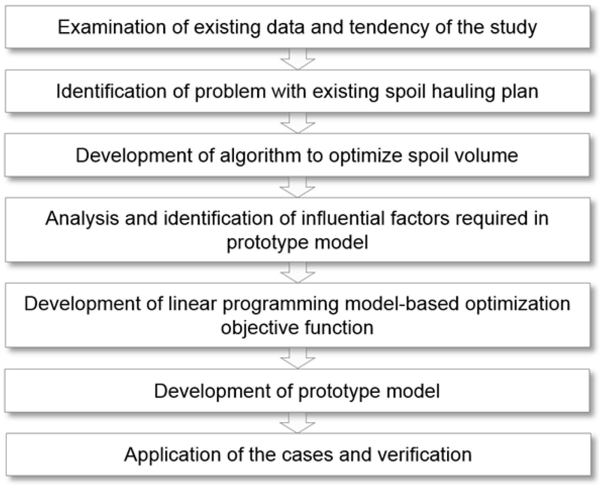
1.2. Scope of Study and Methodology
2. Theoretical Review
2.1. Trend of Related Studies
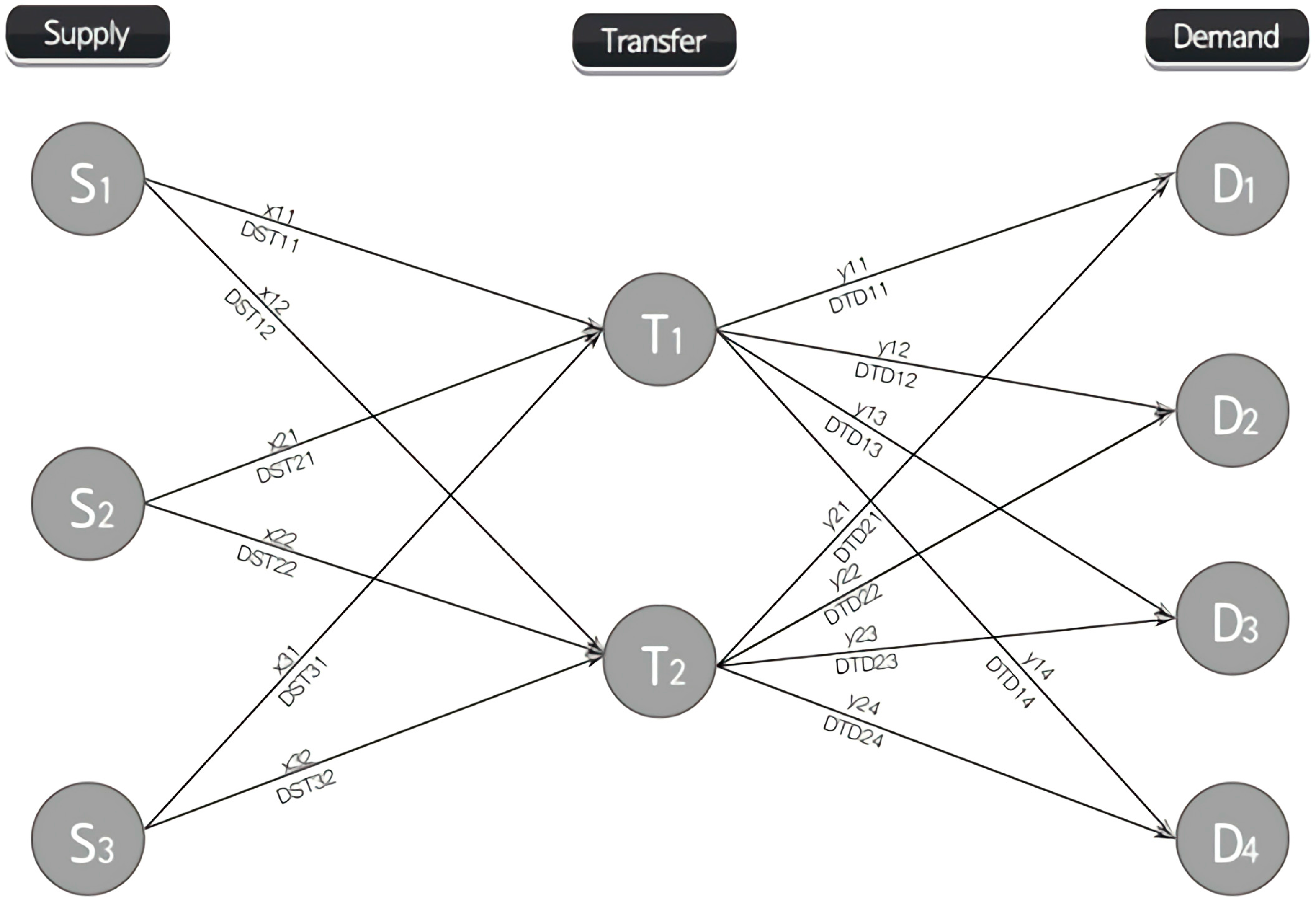
2.2. Transshipment Transportation Model Theory
3. Development of Prototype Model for Establishing Optimal Spoil Hauling Plan
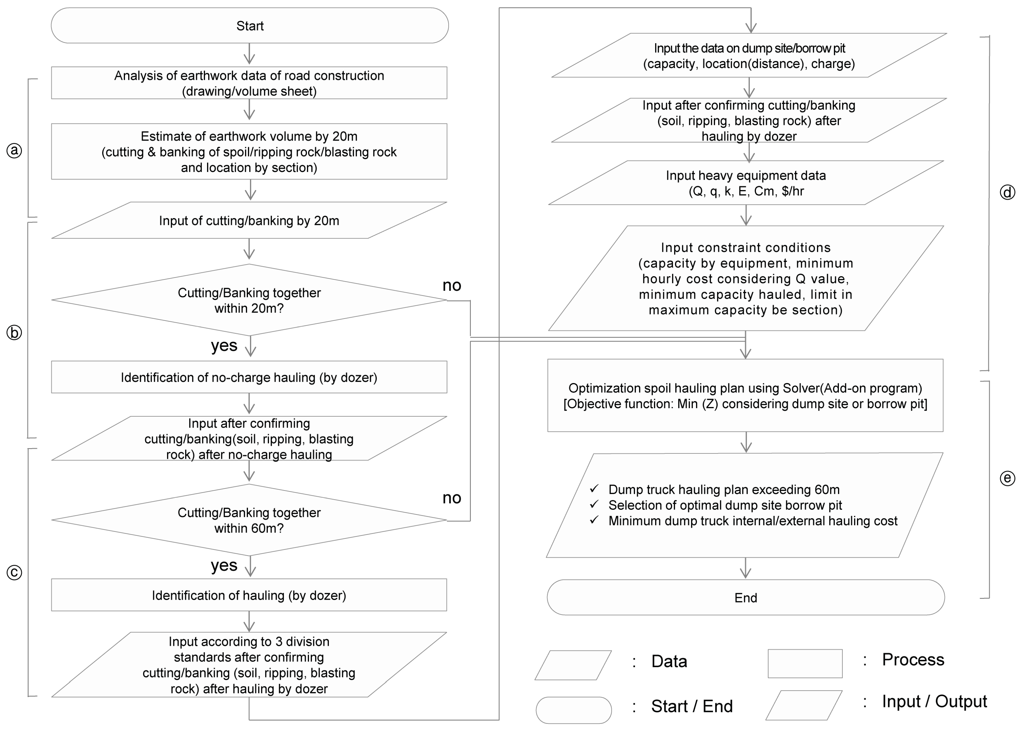
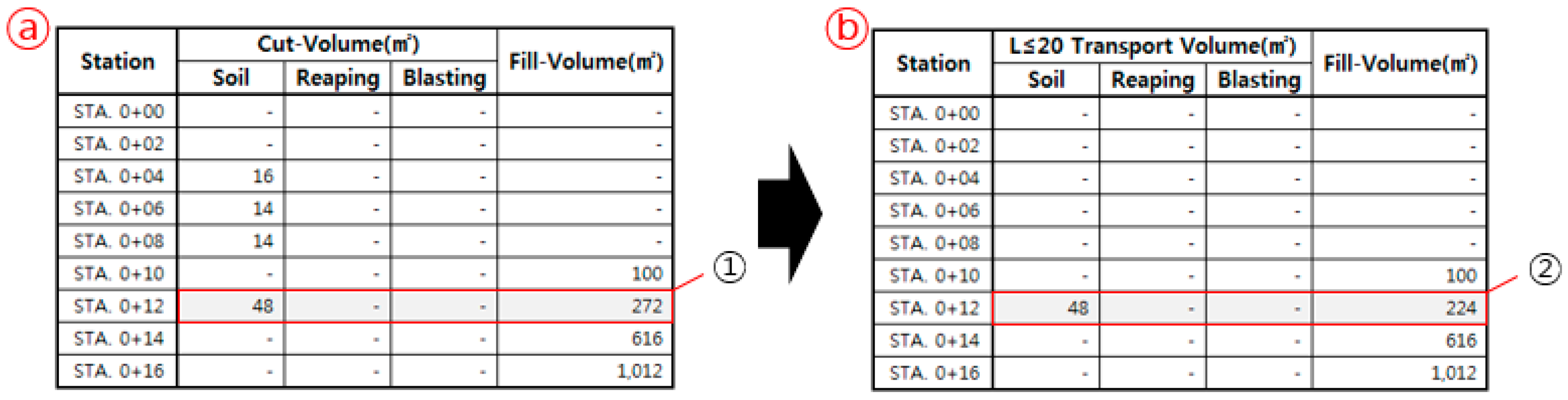
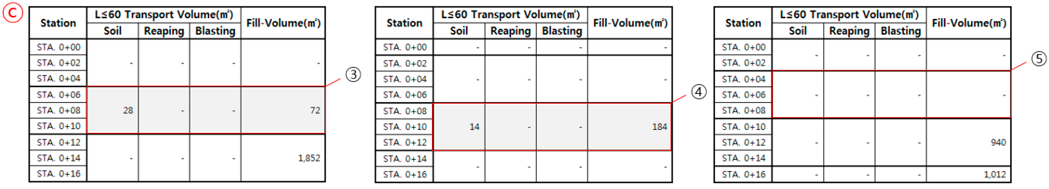
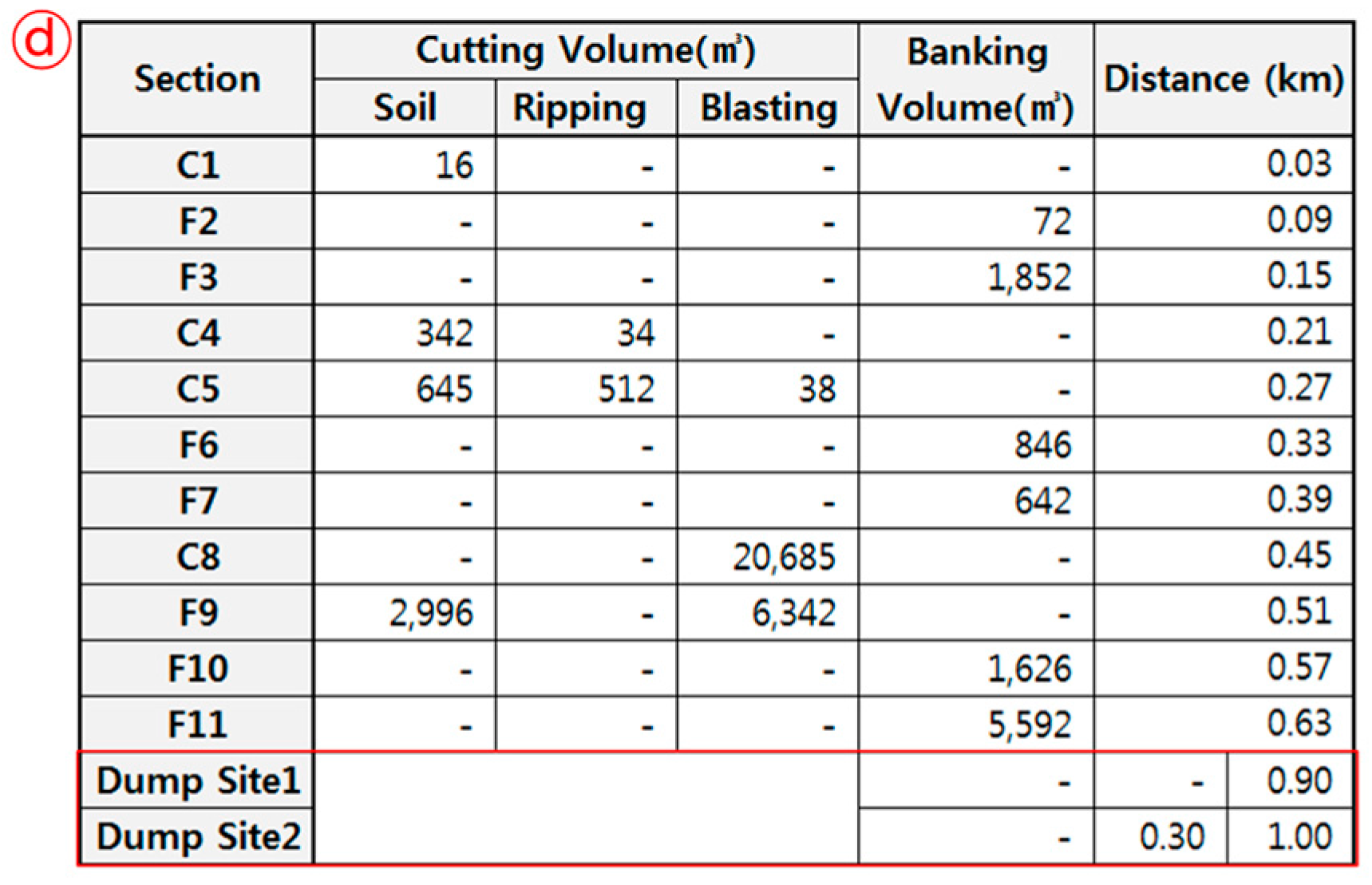
3.1. Algorithm for Optimizing Earthwork Hauling Plan
3.2. Influential Factors and Objective Function of Optimal Process Model for Earthwork Hauling Plan
3.2.1. Influential Factors
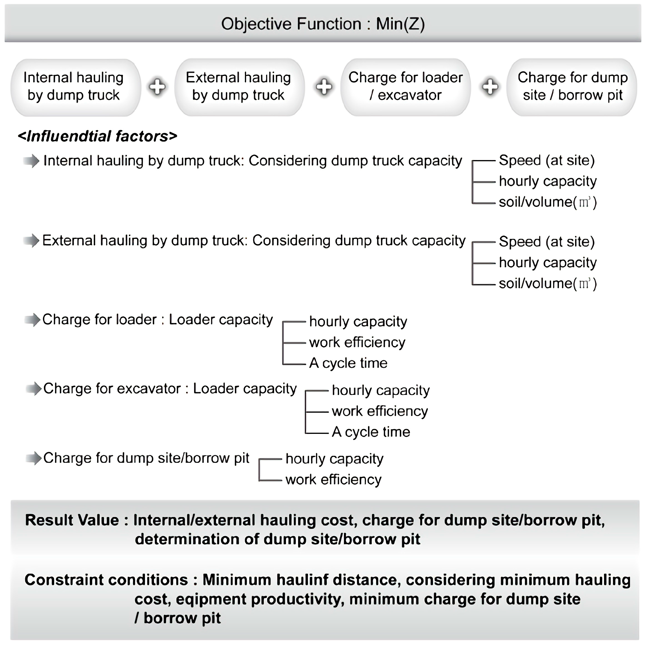
3.2.2. Objective Function
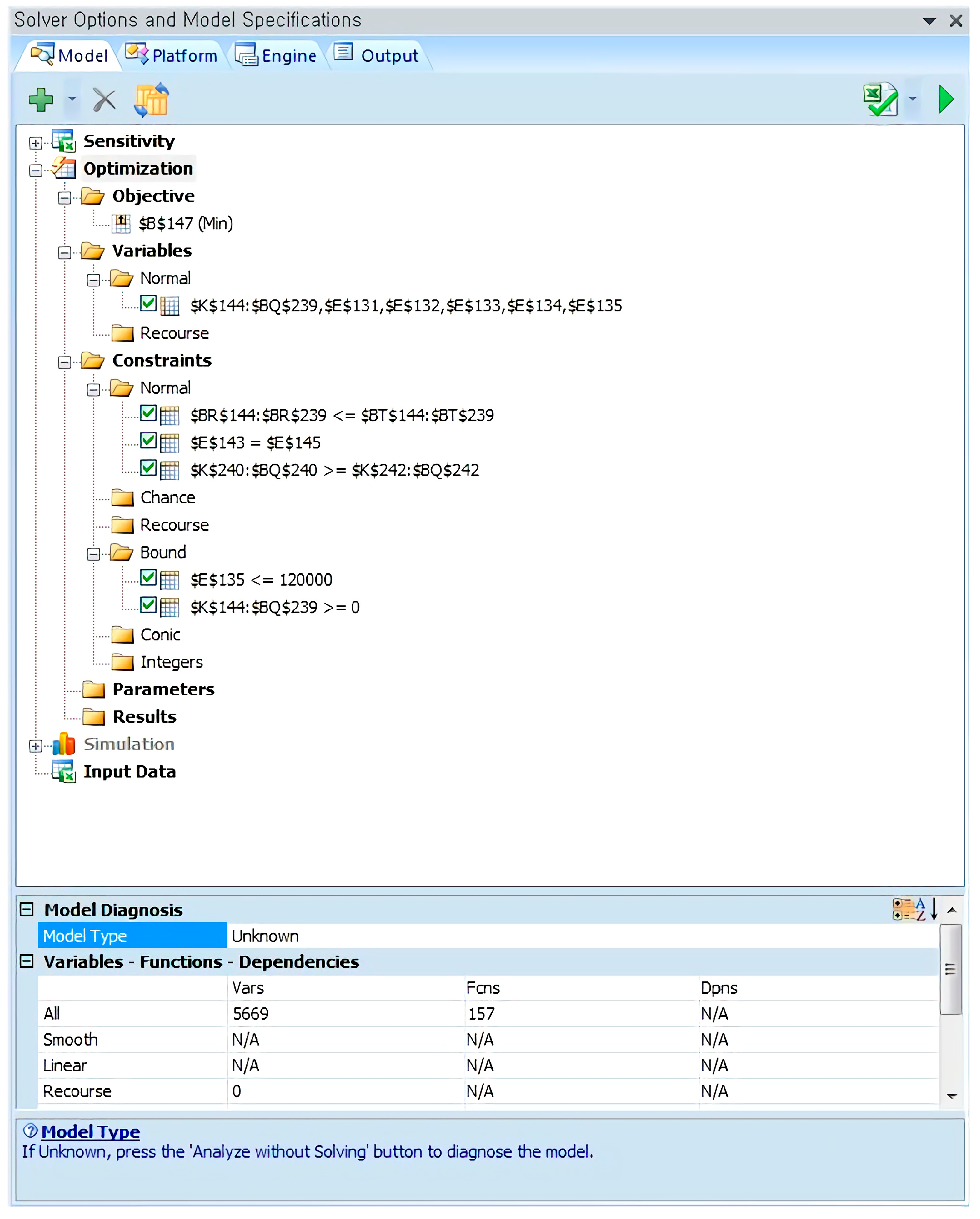
3.3. Development of Prototype Model for Earthwork Hauling Plan
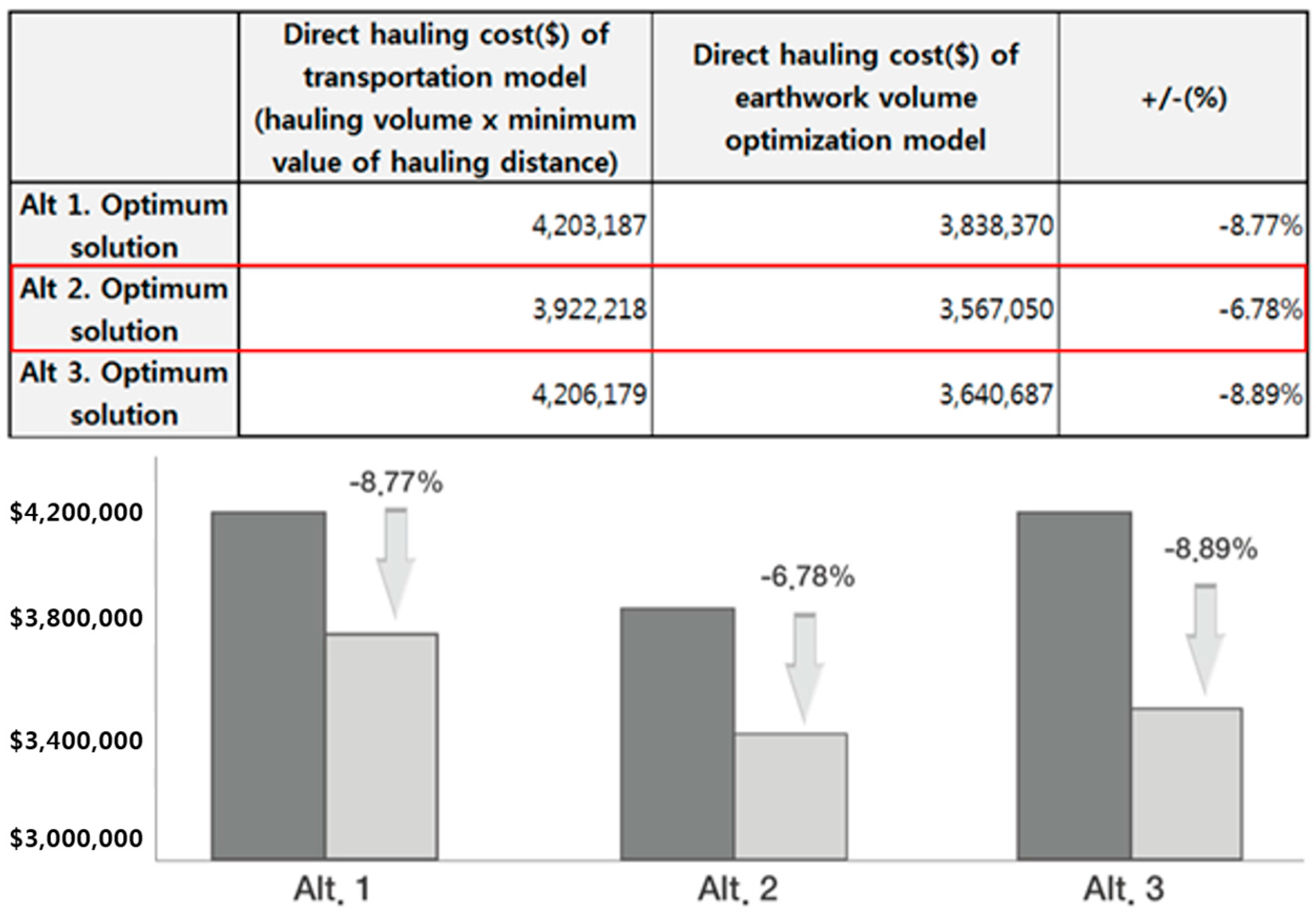
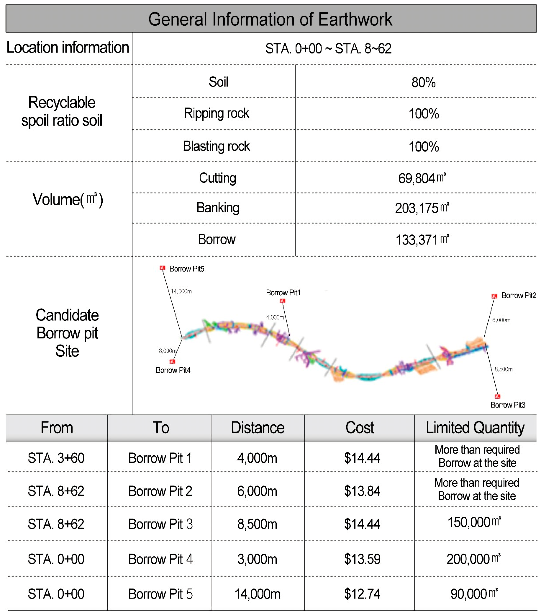
4. Case Studies
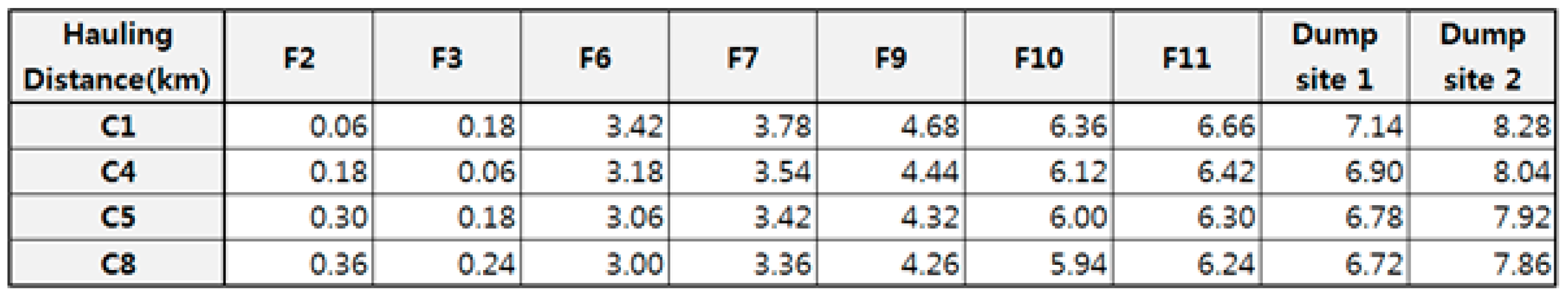
4.1. Case Study 1
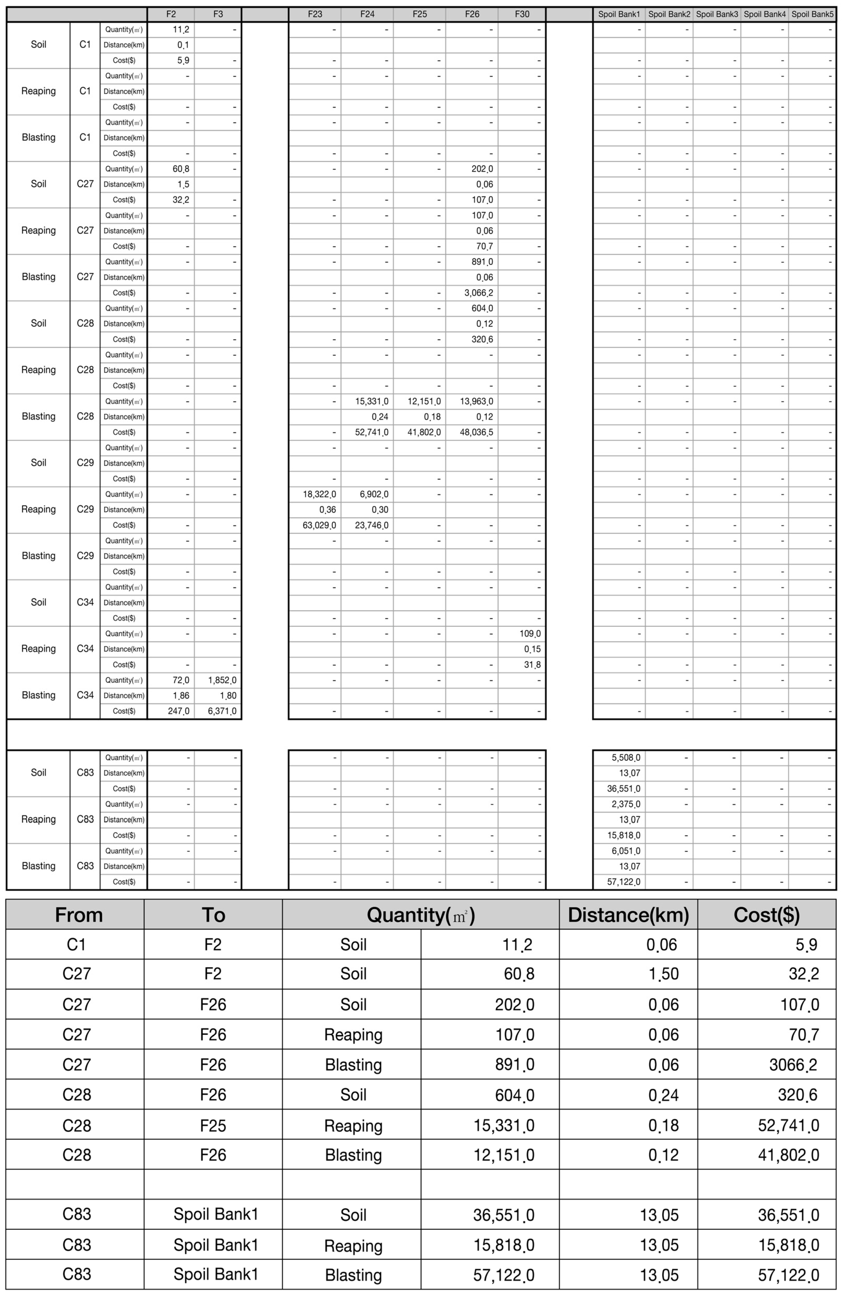
4.2. Case Study 2
5. Conclusions
Acknowledgments
Author Contributions
Conflicts of Interest
References
- Baek, H.; Kang, S.; Seo, J. An earthwork districting model for large construction project. J. Korean Soc. Civ. Eng. 2005, 35, 715–723. [Google Scholar] [CrossRef]
- Baek, K.; Kang, S.; Seo, J. Temporary haul road and bridge planning based on economic efficiency and productivity. In Proceedings of the Construction Research Congress 2016, San Juan, PR, USA, 31 May–2 June 2016.
- Mayer, R.H.; Stark, R.M. Earthmoving logistics. J. Constr. Div. 1981, 107, 297–312. [Google Scholar]
- Easa, S.M. Earthwork allocations with nonconstant unit costs. J. Constr. Eng. Manag. 1987, 113, 34–50. [Google Scholar] [CrossRef]
- Easa, S.M. Earthwork allocations with linear unit costs. J. Constr. Eng. Manag. 1988, 114, 641–655. [Google Scholar] [CrossRef]
- Moselhi, O.; Alshibani, A. Optimization of earthmoving operations in heavy civil engineering projects. J. Constr. Eng. Manag. 2009, 135, 948–954. [Google Scholar] [CrossRef]
- Nassar, K.; Hosny, O. Solving the least-cost route cut and fill sequencing problem using particle swarm. J. Constr. Eng. Manag. 2012, 138, 931–942. [Google Scholar] [CrossRef]
- Park, D.; Kang, I.; Kim, S.; Han, K. The selection of spoil-bank for reduction of carbon emission based on GIS analysis. J. Korean Soc. Geospat. Inf. Syst. 2012, 24, 3–9. [Google Scholar] [CrossRef]
- Son, J.; Mattila, K.; Myers, D. Determination of haul distance and direction in mass excavation. J. Constr. Eng. Manag. 2005, 131, 302–309. [Google Scholar] [CrossRef]
- Ji, Y.; Borrmann, A.; Rank, E.; Seipp, F.; Ruzika, S. Mathematical modeling of earthwork optimization problems. In Proceedings of the 13th International Conference on Computing in Civil and Building Engineering (ICCCBE-XIII), Nottingham, UK, 30 June–2 July 2010.
- Jassim, H.S.H.; Lu, W.; Olofsson, T. A practical method for assessing the energy consumption and CO2 emissions of mass haulers. Energies 2016, 9, 802. [Google Scholar] [CrossRef]
- Ministry of Land, Infrastructure and Transport. Earthwork. In Standard Estimate for Construction Work; Korea Institute of Civil Engineering and Building Technology: Sejong, Korea, 2015; pp. 785–796. [Google Scholar]
- Ministry of Land, Infrastructure and Transport. Transaction of Soil Rock Open Portal ReCYCLE System. Available online: www.tocycle.com (accessed on 26 August 2015).


| Factor | Equipment |
|---|---|
| F (volumetric conversion factor), E (work efficiency), Cm (one cycle time (s)), q (bucket capacity), K (bucket coefficient), t1 (time to fill bucket with spoil), t2 (Basic time such as gear change and time till following equipment arrives) | Loader |
| F (volumetric conversion factor), E (work efficiency), Cm (one cycle time (s)), q (bucket capacity), K (bucket coefficient) | Excavator |
| Q (loading capacity of dump truck), f (volumetric conversion factor), E (work efficiency), Cm (one cycle time (m)), Es (work efficiency of loader), n (cycle of loading machine to finish loading a dump truck), t1, t2, t3, t4, and t5 (components of one cycle time; m), hauling road and mean travel speed (V1, V2, V3, V4) | Dump truck |
| Capacity of dump site/borrow pit, hauling distance, recyclable soil ratio | Others |
© 2017 by the authors; licensee MDPI, Basel, Switzerland. This article is an open access article distributed under the terms and conditions of the Creative Commons Attribution (CC-BY) license (http://creativecommons.org/licenses/by/4.0/).
Share and Cite
Lee, S.H.; Son, J.; Lee, S.H. Development of a Prototype Model to Establish an Economic Earthwork Plan that Includes the Selection of a Dump Site/Borrow Pit. Sustainability 2017, 9, 74. https://doi.org/10.3390/su9010074
Lee SH, Son J, Lee SH. Development of a Prototype Model to Establish an Economic Earthwork Plan that Includes the Selection of a Dump Site/Borrow Pit. Sustainability. 2017; 9(1):74. https://doi.org/10.3390/su9010074
Chicago/Turabian StyleLee, Seung Hak, Jaeho Son, and Seung Hyun Lee. 2017. "Development of a Prototype Model to Establish an Economic Earthwork Plan that Includes the Selection of a Dump Site/Borrow Pit" Sustainability 9, no. 1: 74. https://doi.org/10.3390/su9010074