Stability Control of Retained Goaf-Side Gateroad under Different Roof Conditions in Deep Underground Y Type Longwall Mining


1
College of Geological and Mining Engineering, Xinjiang University, Urumchi 830047, China
2
Department of Earth Resources Engineering, Kyushu University, Fukuoka 819-0395, Japan
*
Author to whom correspondence should be addressed.
Sustainability 2017, 9(10), 1671; https://doi.org/10.3390/su9101671
Submission received: 5 September 2017
/
Revised: 19 September 2017
/
Accepted: 19 September 2017
/
Published: 21 September 2017
(This article belongs to the Section Energy Sustainability)
Abstract
:Stability of the retained goaf-side gateroad (RGSG) is influenced mainly by the movements of the roof strata near coal seam after coalface passes by. To make effective controlling technology for the stability of the RGSG, we analyze the roof structure over the RGSG to illustrate the mechanism causing the RGSG instability under different roof conditions. We then examine the dynamic evolution of the deformation and abutment stress in the rock surrounding the RGSG during coal seam mining, using the FLAC3D numerical software to reveal the instability characteristics of the RGSG under different roof conditions. Next, corresponding stability controlling technologies for the RGSGs are proposed and tested in three typical deep underground coalmines. Results show that: sink and rotation of the roof cantilever over the RGSG impose severer influence on the stability of the RGSG. The RGSG suffers disturbances three times during the coal-seam mining, and the deformation and abutment stress in the rock surrounding the RGSG increase significantly when the main roof becomes thicker and the immediate roof becomes thinner. Staged support technology involving grout cable bolts has better controlling results of the RGSG stability than that composed of conventional rock bolts, when the RGSG is beneath weak immediate roof with large thickness. Roof structure optimizing technology involving pre-split technology can improve the stability of the RGSG effectively when the RGSG is covered by hard main roof with large thickness directly.
1. Introduction
1.1. Advantages of the Y Type Longwall Mining
For sustainable utilization of limited coal resources, it is important to increase the coal recovery rate and reduce gas emission from the underground mining area [1]. U type longwall mining (Figure 1a) has been widely used in underground coalmines for its high productivity and recovery rate. As the mining depth increases, however, the advantages of the longwall mining system with U-shaped gateroads diminish obviously. The high gas content and heat emission found in deep coalmines always lead to gas overrun in the upper corner (red star in Figure 1a) and extremely high temperatures at the coalface. Therefore, additional gateroads with larger sections are excavated to eliminate the gas and heat accumulation [2,3]; this increases the cost of driving and maintaining the gateroads. The high stress in the deep environment requires larger gateroad protection coal pillars between two adjacent longwall panels to bear the heavy weight of the overlying strata. Having larger pillars also decreases the coal recovery rate and causes high stress concentration [4,5]. Moreover, creating the new gateroads for the second coal panel mining is not fast enough to match the continually increasing coal-panel retreating speed, which again limits the mining productivity.
To resolve these problems, a modified gateroad layout, referred to as the Y-shaped layout (Figure 1b), was proposed, and based on a retained goaf-side gateroad (RGSG). In this system, the original longwall tailgate, which is abandoned in the conventional U-shaped settings as the coalface passes, remains open by the construction of an artificial packfillings (backfill wall) along the side of the goaf as the coalface advances. The RGSG can be used as an outlet for the polluted air from the first coal panel mining. In this setup, there are two gateroads for fresh air flowing in, providing more air with higher pressure through the coalface and upper corner. This improves the airflow route, and gas and heat accumulation is eliminated effectively [6]. The RGSG can also improve the efficiency of gas extraction from the goaf and the adjacent fractured strata by providing the space for gas drainage holes drilling. As a result, potential risks of gas explosion and air pollution can be reduced. In addition, the RGSG can be reused as an inlet for transport and fresh air during the mining of the second coal panel, reducing the time and cost of driving a new gateroad for the mining of the second coal panel. Moreover, the wide gateroad protection coal pillar between the two coal panels is replaced by the narrow backfill wall, thus increasing the coal recovery rate.
1.2. Stability Control of the RGSG in the Y Type Longwall Mining
Y-type longwall mining accompanied by an RGSG can resolve the problems that the U-type longwall mining system encounters in a deep mining environment; however, stability control of the RGSG is a challenging issue related to this technology. Abutment stress is the main contributor to the instability of the RGSG. After the coal is excavated (Figure 2), the strata overlying the goaf will crack and sink. At the same time, the in-site stress around the goaf is redistributed until the movement of overlying strata stops [7]. As a result of the stress redistribution, abutment stress forms in the rock surrounding the longwall goaf. Because the coalface moves forward continually, the abutment stress induced by the overlying strata movement varies dynamically. The RGSG is located along the side of the goaf, and is constructed as the coalface advances. Therefore, the RGSG suffers the abutment stress influence during the whole longwall panel mining process.
The final state of the abutment stress around the longwall goaf is determined by the geological condition of the roof strata near the coal seam. Three disturbed zones [8] will form in the strata overlying the longwall goaf (from the bottom up): the caved zone, fractured zone and continuous deformation zone (Figure 2). The wider the disturbed zones, the larger the concentration of abutment stresses. The size of these disturbed zones is controlled mainly by the properties of the rock strata in the caved zone. When the immediate roof is sufficiently thick, the void created by the excavation can be filled completely by the caved rock mass, and the main roof will not crack. The intact main roof can then bear the heavy weight of the overlying strata. Consequently, the coal-seam mining will have only a slight effect on the RGSG. In contrast, when the main roof cracks, the height of the disturbed zone increases, and the RGSG is strongly influenced by the abutment stress induced by the overlying strata movement.
Many valuable studies on the stability control of the RGSG have been carried out recently, while most of these studies focused on RGSG stability under a certain roof condition. For example, Qian studied the size of the RGSG packfillings under weak roof stratum [9]. Feng investigated the position the RGSG under weak roof stratum [10]. Tan proposed a flexible-hard RGSG packfillings under hard roof stratum [11]. Zhang researched the RGSG stability under the roof stratum consist of coal [12]. Wang put forward a novel RGSG packfillings construction method under compound roof [13]. Ning analyzed the stability of the RGSG packfillings in steep coal seam [14]. Very few studies compared the stability of the RGSG under various roof conditions. In addition, the high stress [15] and plastic rock mechanics [16] in the deep mining environment make the stability control of the RGSG more difficult. Study on the RGSG stability controlling technology in deep mining level from the source of roadway instability is of great significance to the sustainable development of coal resources, environment and society, in the current situation that underground mining depth increases quickly because of the depletion of shallow resources around the world.
In this paper, we analyze the roof structures, roadway instability characteristics and stability controlling technology of the RGSG with various thickness values of the immediate roof and main roof. In the analysis, we used typical geological conditions found in deep coalmines in eastern China, where more than 80% of underground coalmines with a depth of more than 1000 m in China are located and Y-type longwall mining is also widely applied.
2. Research Methods
2.1. Deforamtion Model
The movement of the strata overlying the longwall goaf forms a roof cantilever along the goaf side, under which the RGSG is located. Because the weight of the cantilever and overlying strata is too large for the existing roadside packfillings to support, the roof cantilever will crack and sink until it touches the already caved rock mass in the goaf. Such movement has a strong influence on the stability of the strata around the RGSG. As shown in Figure 3, four deformation models were built to illustrate the roof structure over the RGSG when roof condition varies, which will be discussed in detail in Section 3.1.
2.2. Numerical Model
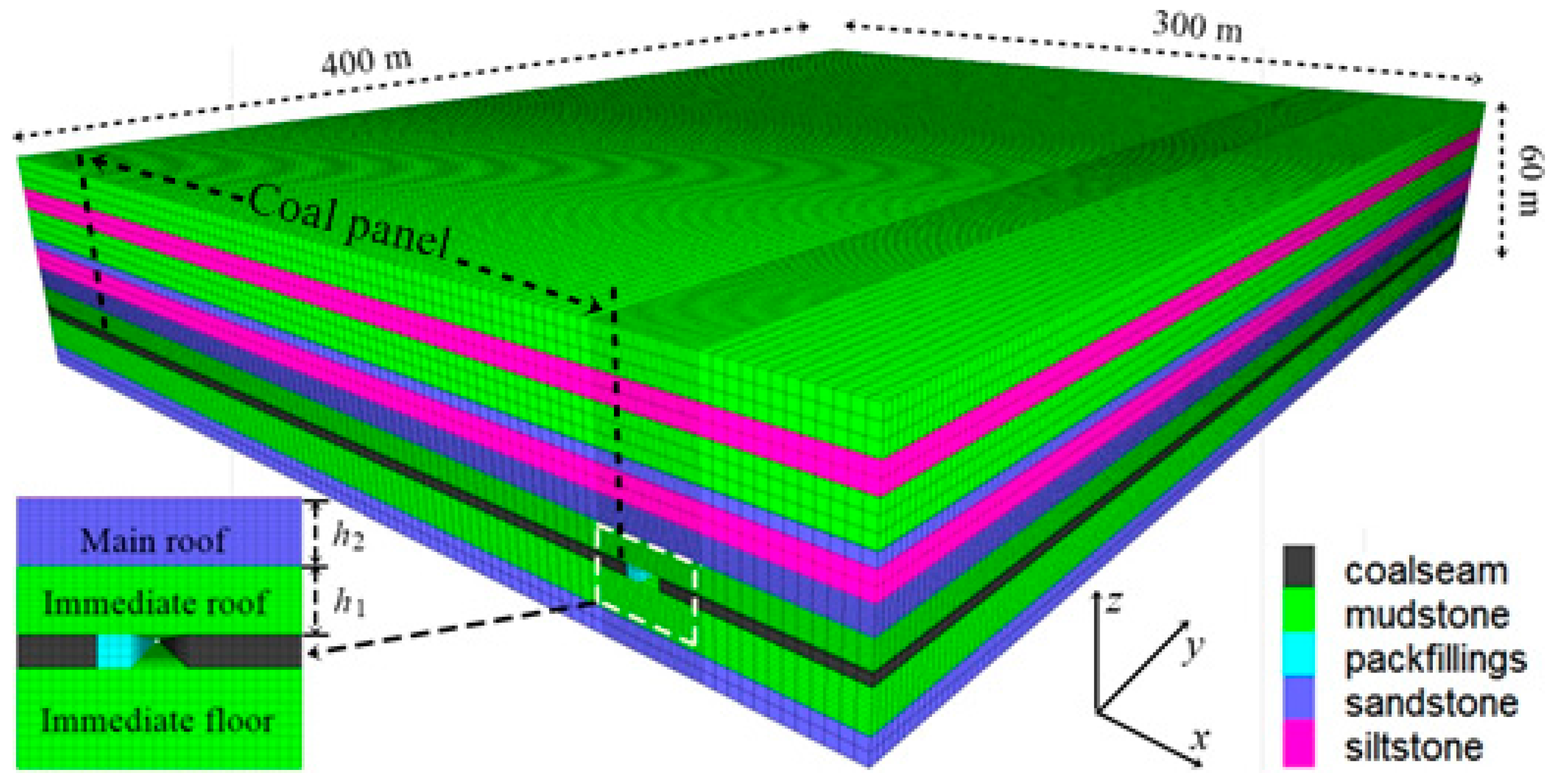
To analyze accurate stress and deformation evolution in rock surrounding of the RGSG, a 3D numerical model (Figure 4) was built based on the above deformation model and the general geological conditions of an underground coalmine with depth of 1000 m in eastern China, using FLAC3D software [17], and several considerations involved in this simulation are listed as follows.
- (1)
- Considering the computing efficiency and accuracy, this model had 1,170,000 zones. Coal seam was 3.0 m thick, and gateroad was 5.0 m wide and 3.0 m high, and packfillings was 3 m wide and 3 m high. Displacement boundaries of the model were set as roller boundaries along sides, and pinned boundary along bottom. A vertical stress as much as 19.7 MPa was applied at the top of model to simulate the weight of overburden assuming the average density of the overlying strata is 2.2 × 10³ kg/m3, and at-rest pressure coefficient was taken as 1.0. Longwall panel moved along the y direction.
- (2)
- In this model, immediate roof was mudstone and main roof was sandstone. To model the caving activity of the immediate roof and supporting of the caved rock mass to overlying strata, the immediate roof was also excavated together with the coal-seam, and the excavated space was filled with soft elastic backfilling [18], as shown in Figure 5. Whole thickness of the immediate roof and the main roof was set to be a certain value of 12 m, which is the thickness that the immediate roof needed to fully fill the excavated space when 3 m thick coal seam was mined, which was calculated according to the Equation (1) assuming the residual bulk factor of the caved immediate mudstone was 1.25. Seven types of the combinations of immediate roof and main roof were considered in this simulation, as shown in Table 1. The thickness of main roof increased as immediate roof became thin gradually, and the backfilling thickness was calculated in each situation according the corresponding thickness of the immediate roof.
- (3)
- Coal seam, immediate roof and floor strata were set as Strain Softening constitutive materials to simulate the plastic mechanics of these weak rock masses in deep mining environment. Other rock strata including sandstone, siltstone and packfillings were set as Mohr–Coulomb constitutive material. The mechanics parameters of all rock masses used in this model were collected according to the results of rock sample tests in lab and statistical investigation in field, and they are listed in Table 2 and Table 3.
- (4)
- Roadway support was installed according to the present criterion applied in eastern China: rock bolts (end anchored) with a diameter of 22 mm and a length of 2500 mm in roof with an inter-row space of 0.9 m × 0.8 m and in coal sidewalls with an inter-row space of 0.75 m × 0.8 m; cable bolts (end anchored) with a diameter of 22 mm and a length of 6000 mm only in roof strata and right coal sidewall, with an inter-row space of 1.0 m × 0.8 m. In the left coal sidewall, cable bolt was not installed because the obstruction to coal cutting. Roadway floor was not supported.
- (5)
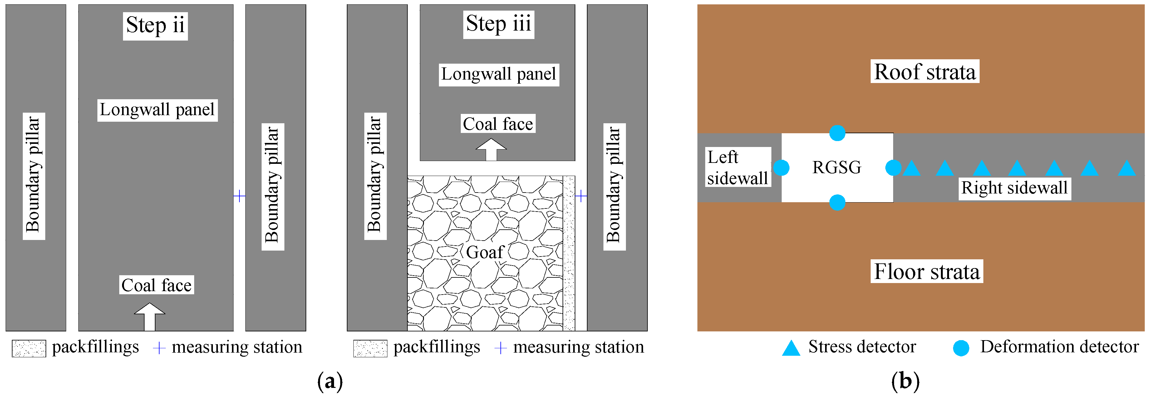
- The simulation sequences are as follows: (i) generating initial stresses; (ii) excavating the gateroad and installing roadway support; and (iii) retreating coal panel and building the packfillings along the goaf side (Figure 6a). During coalface moving, abutment stress and deformation in roadway’s surrounding rock were monitored according to the measuring station and detectors shown in Figure 6a,b, and the monitored results were analyzed in Section 3.2 and Section 3.3.
3. Results and Discussion
3.1. Roof Structure over the RGSG as Roof Condition Varies
When the immediate roof is sufficiently thick, the goaf will be completely filled after the coal is mined (Figure 3a). In this case, the main roof does not crack and most of the weight of the overlying strata is supported by the intact main roof; the influence of the overlying strata movement on the RGSG is minimal.
As the thickness of the weak immediate roof decreases, the caved rock mass cannot fill the excavated space after compaction. Because of the insufficient support of the caved rock mass and the heavy load from the overlying strata, the main roof will break (Figure 3b). The movement of the broken roof cantilever can be modeled as a rotation around pivots located on the crack; the broken roof rotates until the bottom touches the caved rock mass in the goaf. The subsidence (Δh) of this roof cantilever at its outer edge can be calculated according to Equation (1).
where h1 is the thickness of the immediate roof; m is the thickness of the coal seam; and k is the residual bulk factor of the caved rock mass.
The rotation angle (φ) can be calculated using Equation (2).
where L is the length of the main roof cantilever, determined by the mechanical characters of the main roof. The harder and thicker the main roof, the longer the cantilever.
In this situation, subsidence of the roof cantilever compresses the underlying rock mass, including the rock surrounding the RGSG. The deformation of the roadway surrounding rock is larger than that in the first situation, and the compressive strength on the packfillings also increases.
When the thickness of the immediate roof decreases gradually (Figure 3c), the subsidence (Δh) and the rotation angle (φ) of the main roof cantilever increase accordingly. As a result, a longer and thicker roof cantilever will form over the RGSG. Increased roof subsidence caused by the rotation of the longer main roof cantilever leads to more compression in the underlying rock mass and weakens the rock surrounding the RGSG.
In the case with no immediate roof, where the coal seam is covered directly by the hard main roof, the RGSG stability is most difficult to control (Figure 3d). Because of its strength, the hard roof does not break for a long time after coal extraction. Therefore, the heavy load from the large roof area is imposed on the rock surrounding the underlying working space, especially on the RGSG at the edge of the goaf. When the hard roof breaks, a larger free space (Δh = m) is present underneath the long rock cantilever. The large deformation energy generated by the main roof cantilever subsidence is absorbed by the rock surrounding the RGSG apart from the roof. As a result, the RGSG floor, packfillings and coal sidewall are weakened significantly. The packfillings will collapse from the increased compression and is likely to topple because of the additional horizontal force generated by the roof cantilever rotation. Wind blast damage is also likely to occur when the hard roof cracks. In this situation, the roadway support should be focused on reducing the influence of the hard roof cantilever movement through roof structure improvement.
3.2. Deformation Evolution during Coal-face Advancement
To understand the behavior of the rock surrounding the RGSG under different roof conditions during coal-seam mining, the deformations of the roadway roof, floor and sidewalls were measured using the measuring station and detectors as shown in previous Figure 6; the results are shown in Figure 7a–d. The horizontal axis shows the relative distance from the measuring station to the coalface, with positive values representing the distance ahead of the coalface, and negative values representing the distance behind the coalface. The deformation of the rock surrounding the RGSG increases as the distance behind the coalface increases. The thicker and thinner the main roof and the immediate roof are, respectively, the faster the deformation rate of the rock surrounding the RGSG and the larger the deformation value.
The roof sag, floor heave and sidewalls convergence increased slightly from 40 m to 20 m ahead of the coalface, and then rose quickly from 20 m ahead of the coalface to 60 behind the coalface. The highest deformation rate occurred about 20 m behind the coalface. As the distance behind the coalface increased, the deformations continued at a slower rate, reaching maximum deformation approximately 120 m from the coalface. The maximum roof sag increased from 580 mm in roof condition I to 920 mm in roof condition VI. When the roof condition changes from type VI (10 m main roof + 2 m immediate roof) to type VII (12 m main roof + 0 m immediate roof), however, roof sag showed an obvious decrease. The maximum value of the floor heave increased from 495 mm in roof condition I to 1350 mm in roof type VII. The maximum value of the left sidewall convergence increased from 579 mm in roof condition I to 970 mm in roof condition VII. The maximum value of the right sidewall convergence increased from 667 mm in roof condition I to 1070 mm in roof condition VII. It should be noted that the increment of floor heave and left sidewall from roof condition VI to VII was considerably larger than other increments when the roof condition changes. The left sidewall convergence started to increase 60 m before the coalface when the RGSG is under roof condition VII.
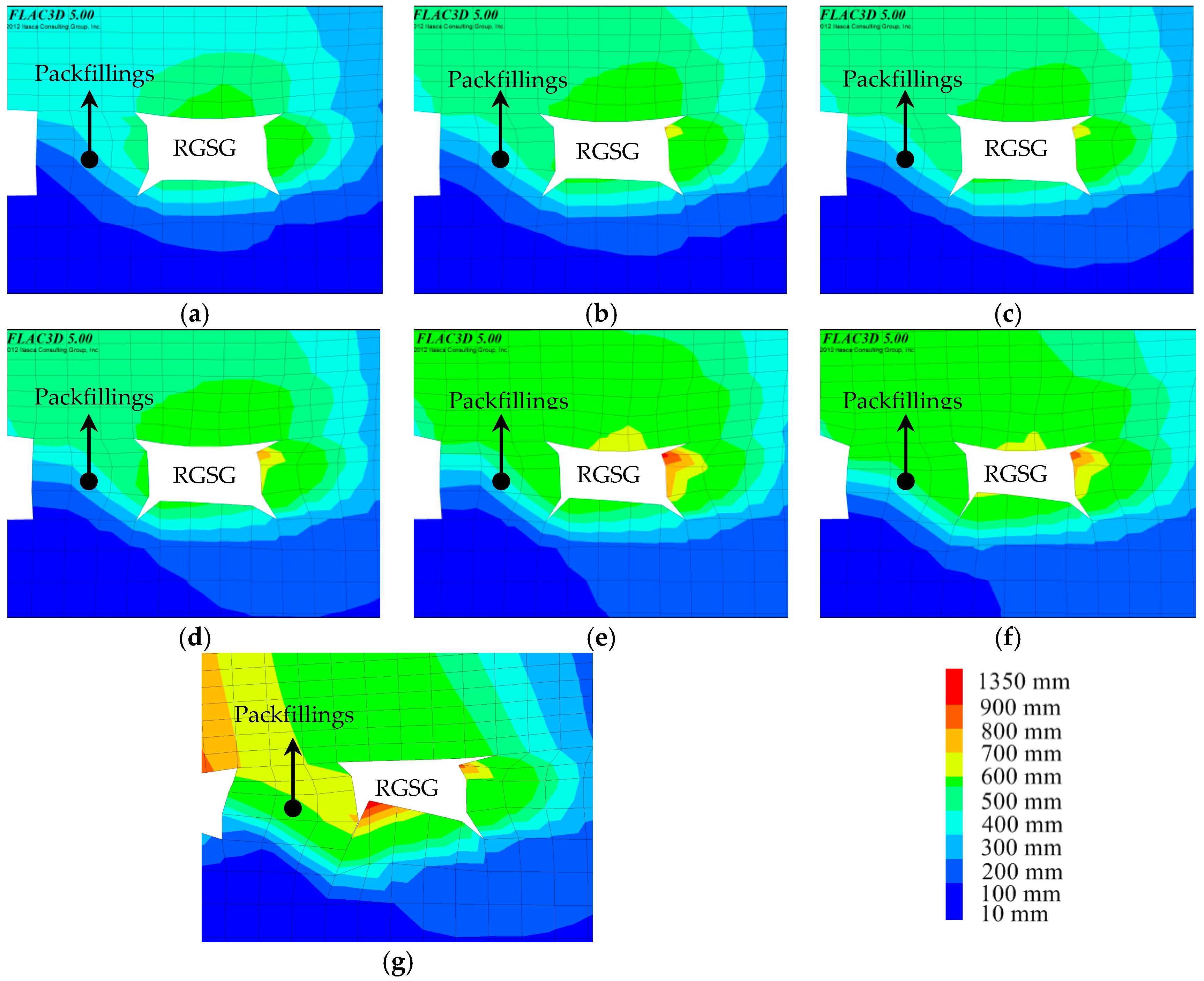
Figure 8 illustrates the final deformation contours of the rock surrounding the RGSG under different roof conditions. The deformation was gradually transferred from the roof to the sidewalls and floor as the roof conditions change. All the surrounding rock including the roof, floor and sidewalls contributed to the roadway section shrinkage when the RGSG was under roof type I. As the main roof became thicker and the immediate roof becomes thinner, the deformation of the sidewalls and floor increased gradually. When the RGSG was covered directly by a hard main roof (roof condition VII), roof sag decreased and the main contributor to the roadway section shrinkage was the large floor movement. Actually, the final deformation of the surrounding rock towards the RGSG space is composed of integral movement and volume expansion itself, and the latter is mainly attributed to the cracks and fissures formation inside. For the roof strata, the contribution of the volume expansion to the final sag decreases significantly when the RGSG is covered by the hard main roof directly, because the weak immediate roof where most of the volume expansion comes from disappears. It is the reason why the roof sag experiences an apparent decrement when roof condition changes from type VI to type VII. The hard main roof is stronger than the right sidewall (composed of soft coal) and the unsupported floor. The roof cantilever sinking and rotation movement compressed the RGSG packfillings and sidewall. As a result, the packfillings and right sidewall expanded in the horizontal direction and were compressed in the vertical direction. Meanwhile, a vertical force was transferred to the RGSG floor through the packfillings and right sidewall, causing the large floor movement from the vertical extrusion on both sides. In addition, the largest floor movement occurred at the bottom-left corner and the largest sidewall convergence happened at the top-right corner.
3.3. Abutment Stress Evolution during Coal-face Advancement
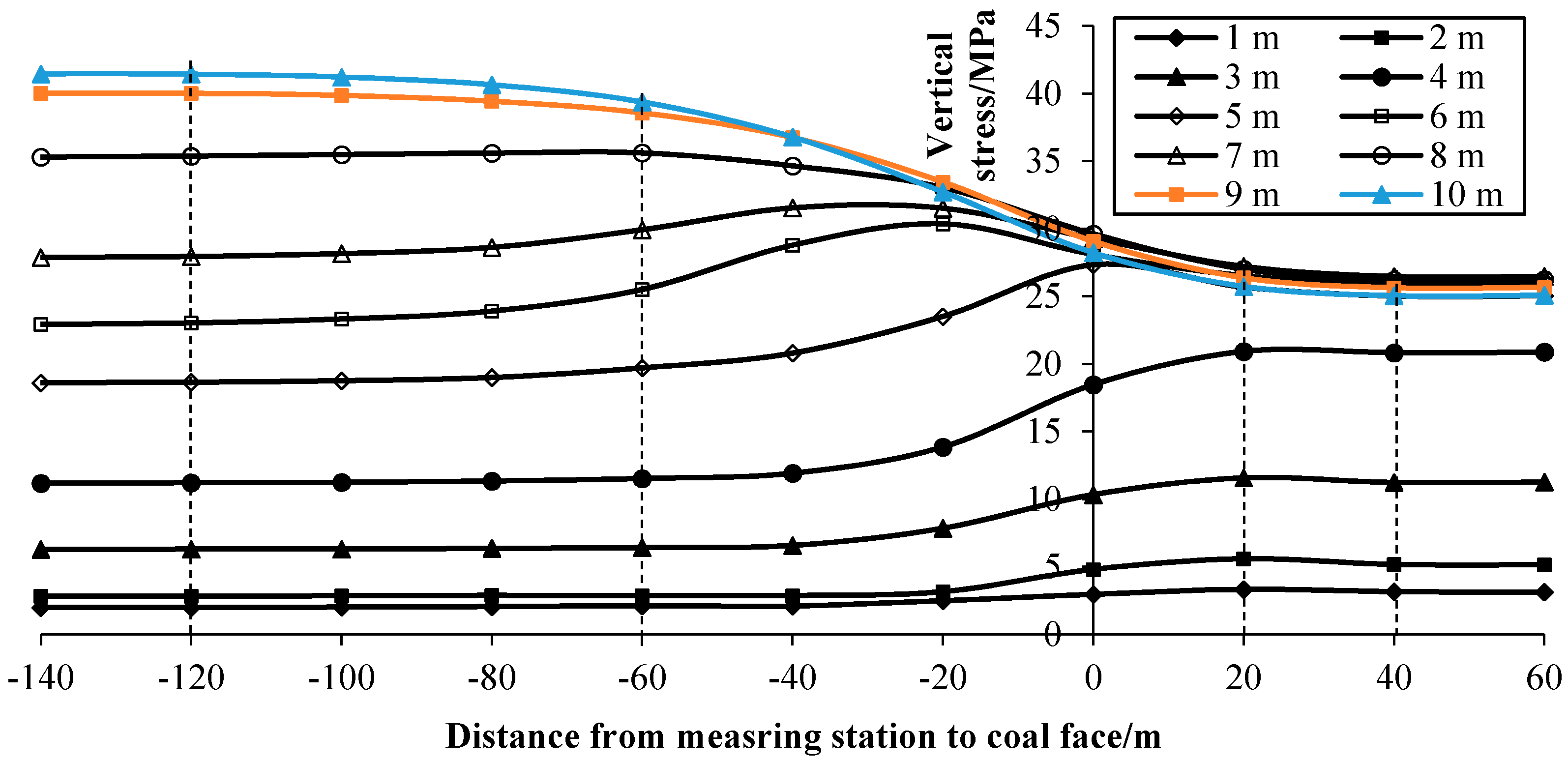
Abutment stress generated by overlying strata movement is the main cause of RGSG instability. First, the RGSG under roof condition I (12 m immediate roof + 0 m main roof) was selected as the basic model for studying the general distribution of abutment stress in the rock surrounding the RGSG. Figure 9 represents the distribution of the abutment stresses in the RGSG right sidewall at different distances from the sidewall surface during coal-seam mining.
The abutment stresses in the right sidewall increased slowly from 40 m ahead of the coalface; when the distance behind the coalface decreased to 20 m, the abutment stresses within 4 m from the sidewall surface decreased, and those beyond 4 m increased. As the coalface moved forward, the abutment stresses 5–7 m from the sidewall surface decreased, while those beyond 7 m increased rapidly until 60 m behind the coalface. As the distance behind the coalface increased, the abutment stress 8 m from sidewall surface decreased slightly, and the abutment stresses 9 m and 10 m inside the right sidewall slightly increased to maximum values of 40 MPa and 41 MPa, respectively, measured 120 m behind the coalface. As the coalface moved further, the abutment stresses in the RGSG right sidewall remained constant.
The results indicate that: (1) The influence of the abutment stress on the RGSG can be divided into three stages: no influence farther than 40 m ahead of the coalface and 120 behind the coalface; slight influence 40–20 m ahead of the coalface and 60–120 m behind the coalface; strong influence from 40 m ahead of the coalface to 60 m behind the coalface. The evolution of the abutment stress in the right sidewall is in good agreement with the deformation variations of the rock surrounding the RGSG. (2) The decrease of the abutment stresses near the sidewall surface and the transfer of the peak abutment stress inside the sidewall both indicate that part of the RGSG sidewall has gone into a plastic state, and this plastic zone widens gradually as the mining of the coal seam proceeds.
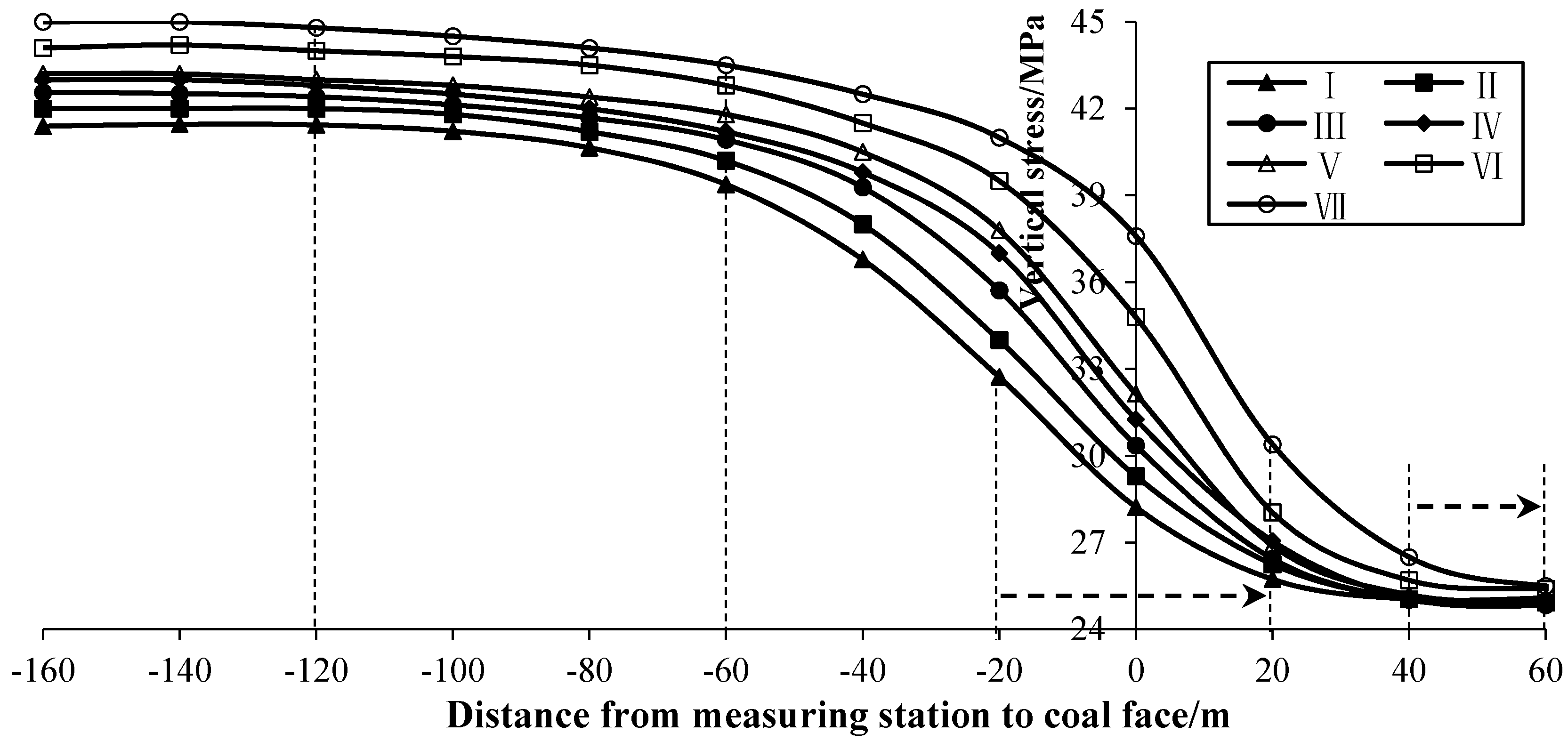
As discussed above, part of the rock mass near the surface of the rock surrounding the RGSG deformed, broken and showed plastic behavior under the influence of the coal-seam mining. The rock located far from the surrounding rock surface was still stable and able to bear large stresses. Based on this, the evolution of the abutment stress 10 m inside the RGSG right sidewall was selected as the reference indicator to identify the influence of different roof conditions on the abutment stress distribution.
As shown in Figure 10, the position where the abutment stress started to increase moves further from the coalface as the thickness of the main roof increased and that of the immediate roof decreased. For example, the abutment stress in roof condition I started to increase about 40 m ahead of the coalface, while the abutment stress in roof condition VII began to rise approximately 60 m ahead of the coalface. The point with the sharpest rise in the abutment stress also shifted forward as the roof condition changed. For instance, the sharpest increase in the abutment stress occurred about 20 m behind the coalface in roof condition I, while, in roof condition VII, the sharpest abutment stress increase occurred about 20 m ahead of the coalface. Thus, the influence induced by coal seam mining on the RGSG occurred earlier when the main roof was thicker and the immediate roof was thinner. The abutment stress also increased when the roof condition changed from I to VII. For example, when the roof condition changed from I to VII, the abutment stress increased from 25.7 MPa to 30.4 MPa 20 m before the coalface, from 28.2 MPa to 37.6 MPa when the coalface passed by, from 39.4 MPa to 43.5 MPa 60 m behind the coalface, and finally from 41.0 MPa to 44.8 MPa 120 m behind the coalface. Thus, the influence of the moving coalface on the RGSG increased when the main roof became thicker and the immediate roof became thinner, which matches well with the analyses in Section 3.1.
4. Stability Control Technology of the RGSG under Different Roof Conditions
4.1. Staged Support Technology Involving Conventioal Bolts
4.1.1. Staged Support Technology
According to the results of deformation and stress evolution analyzed before, the RGSG suffered the disturbance of coal-seam mining several times as coalface moving. Stability of the RGSG cannot be maintained effectively only by the roadway support during roadway excavation. Therefore, a staged suppor strategy was proposed to deal with the various disturbances. In the first supporting stage, a prestressed bolting system aiming at providing high lateral confining stress was proposed to maintain the stability of the RGSG during roadway excavation. In the second supporting stage, cable bolt system with larger length was suggested within the range influenced by the abutment pressure, considering the deterioration of boltability due to gradually widened plastic zone. In the third supporting stage, a packfillings with increasing bearing strength should be constructed along goaf-side considering the continually increasing abutment stress behind the coalface.
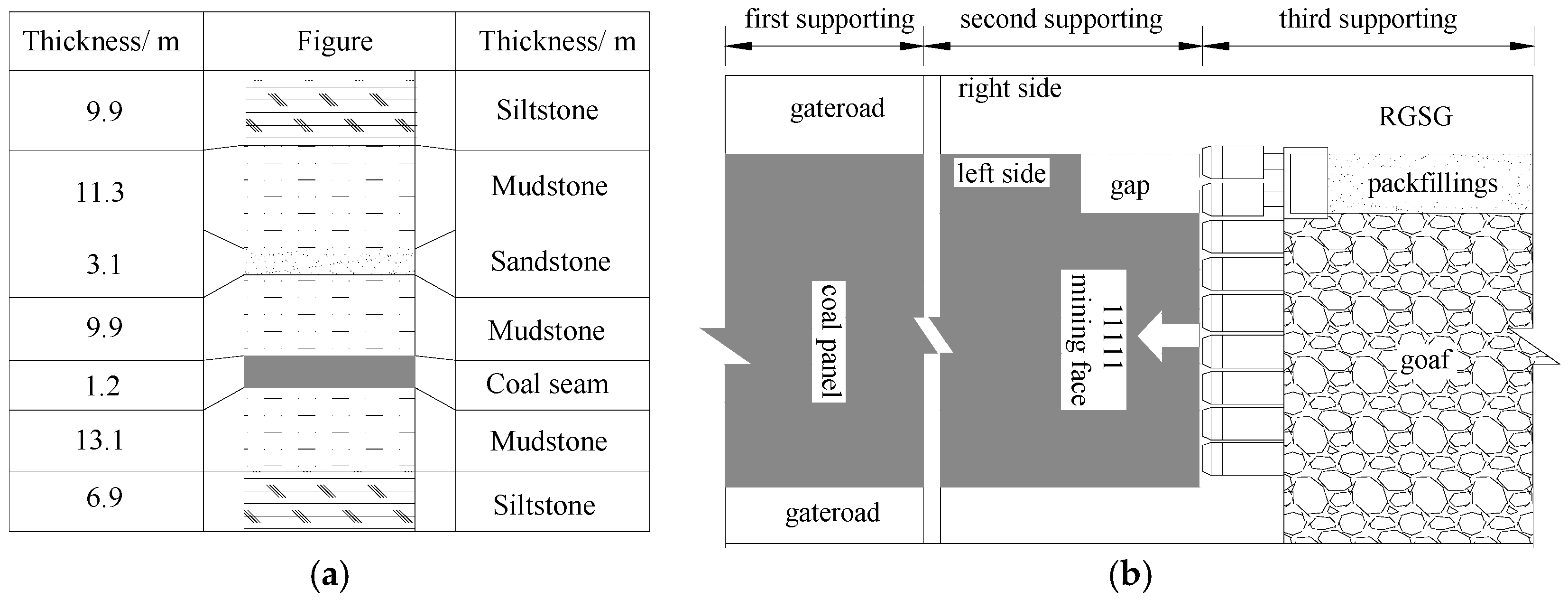
4.1.2. Field Application in Zhuji Coalmine
Zhuji coalmine is located in Huainan city, Anhui Province of China, whose mineable coal seam is buried 980 m underground. Geological columnar section stratigraphy near this mineable coal seam is shown in Figure 11a, and the distribution of the staged roadway support in the RGSG in the Y type longwall mining system is shown in Figure 11b.
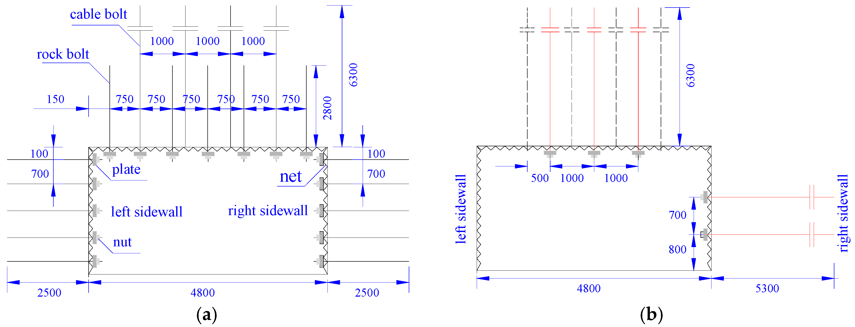
During the first supporting stage, four sets cable bolts and seven sets rock bolt were installed in roof, and five sets rock bolts were installed in sidewalls, and the detailed parameters are shown in Figure 12a. In the second supporting stage, three sets cable bolts (red color) were installed in roof and two set cable bolts were installed in right sidewall. No cable bolts were installed in left sidewall because this part of surrounding rock will be replaced by artificial packfillings. During the third supporting stage, the artificial packfillings was constructed using a mixed material composed of cement 23%, fly ash 8%, gravel 45%, sand 23% and 1% chemical additives by weight.
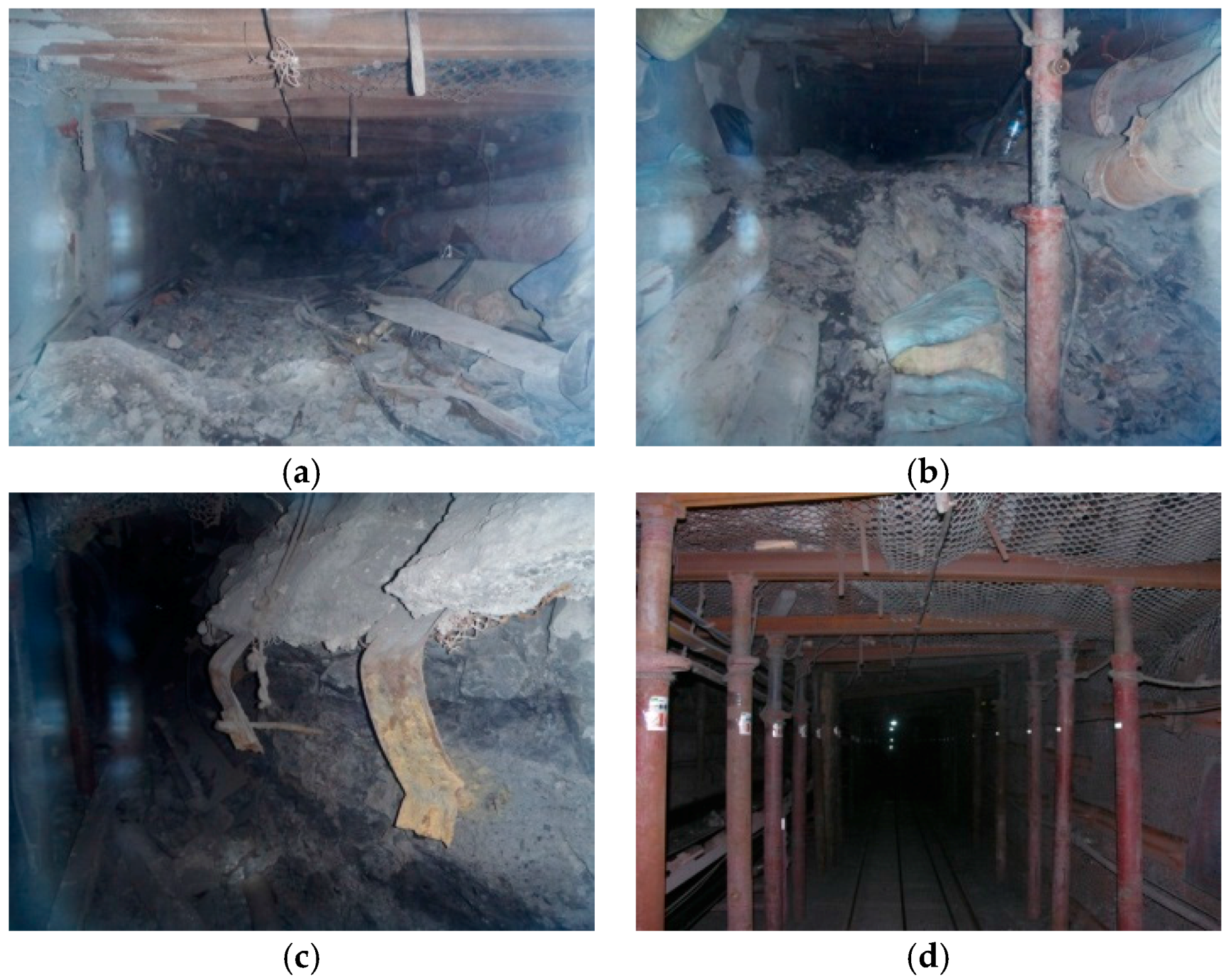
After application of the stage support in the RGSG in the Zhuji coalmine, deformations of the RGSG were measured, and the results are shown in Figure 13. The RGSG supported by the stage support involved conventional rock bolts and cable bolts experienced large deformations after suffering the abutment stress disturbance induced by the first coal panel mining. Residual roadway section was too small to re-serve for the second longwall panel mining. To provide enough space for the second longwall panel mining, floor dinting and sidewall expanding (Figure 14) were carried out after the first longwall panel mining finished, which increased mining cost and the risk of mining accident.
4.2. Staged Support Technology Involving Grout Cable Bolts
Panyidong coalmine is also located in Huainan city, Anhui Province, China, whose minable coal seam is 3 m thick and 850 m deep. Y type longwall gateroads layout was also applied in this coalmine to resolve the problems of high gas emission and severer coal resources waste. Geological condition in the Panyidong coalmine is similar to the Zhuji coalmine. Immediate roof and floor are both weak mudstone with thickness of 9 m. Large deformations is expected, and roadway section enlarging process has to be carried out if it is supported by the same support technology used in the Zhuji coalmine. RGSG space enlarging not only increases mining cost, but also endangers mining safety, especially the sidewall expanding that likely triggers roof cracking and caving. According to the analysis in Section 3.3, plastic zone formed in sidewall and then widened gradually under the influence of coal-seam mining. The plastic zone was the main source of sidewall convergence coming from. To reduce the size of plastic zone in the right sidewall of the RGSG in the Panyidong coalmine, grout cable bolt were employed in the second supporting stage. The structure model of the RGSG behind coalface is shown in Figure 15. Width of the plastic zone in right sidewall can be calculated according Equation (3) [19]:
where m is the mining height; λ is the lateral stress coefficient; k is the coefficient of vertical stress concentration; γ is the volume-weight of overburdens; H is the thickness of overburdens; C0 is the cohesion of the coal; φ0 is the friction angle of coal; and Px is the confining stress on coal sidewall surface.
As shown in Equation (3), Volume-weight and thickness of overburdens, mining height, coefficient of vertical stress concentration and lateral stress coefficient are consistent respect to a certain geological condition. Hence, the width of the plastic zone is governed only by the friction angle, cohesion and confining stress, and these parameters can be improved by appropriate geotechnical methods. Grout cable bolt performs obvious superiorities in these aspects. Firstly, large put-out resistance of the grout cable bolt because of full-length anchorage is able to providing high confining stress Px to the sidewall surface. Secondly, the grouts injected into cracked surrounding rock displaces the air and water in cracks and fissures, and then fills and cements the surface of cracks and fissures, thereby increasing the stability of the weak planes. Third, some micro-cracks and fissures that are too small to interact with grouts can be closed due to the compaction of high grouting pressure. Consequently, mechanical parameters such as friction angle and cohesion could be improved [20,21], and the width of the plastic zone can be decreased.
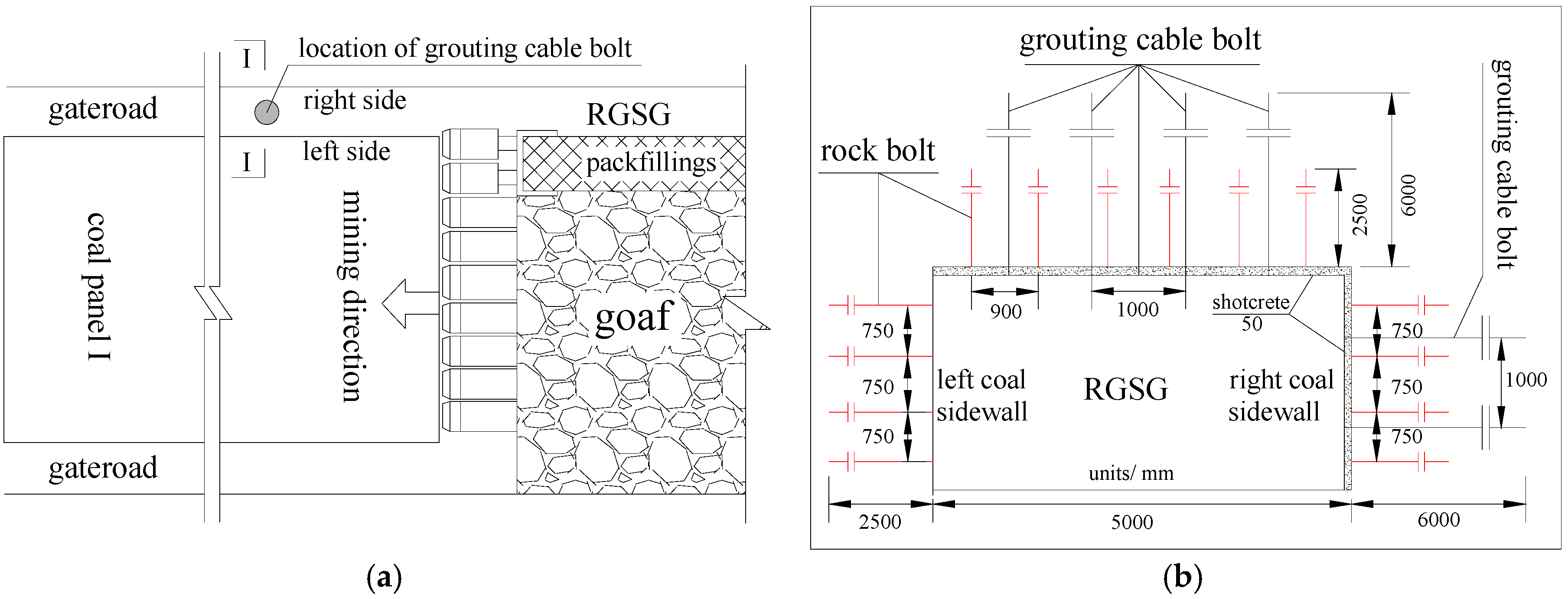
The detailed installation parameters are shown in Figure 16. A series of the grouting cable bolts (in black) were constructed based on the first support system (in red). The grouting cable bolts with a diameter of 22 mm and a length of 6300 mm were installed in the space of original support system, four sets in roof and two sets in the right coal sidewall, and no grouting cable bolts were installed in the left coal sidewall considering the impediments of cable bolt to the coal cutting shearer. Two resin capsules and one steel plate were needed for every cable bolt set, and the designed prestress was larger than 60 kN. Grouts had a ratio of cement (425#) to water of 0.5, a chemical additive (ACZ-I) of 8% by weight; grouting pressure was 2~3 MPa; grouting time was 3~5 min and the thickness of cement lining was 50 mm.
Figure 17 represents the deformation of the RGSG during the first longwall panel mining. After experiencing the stress disturbances, the largest deformation of the RGSG was less than 300 mm, roadway space was large enough for the second longwall panel mining.
4.3. Hard Roof Structure Optimizing Technology Involving Pre-Split
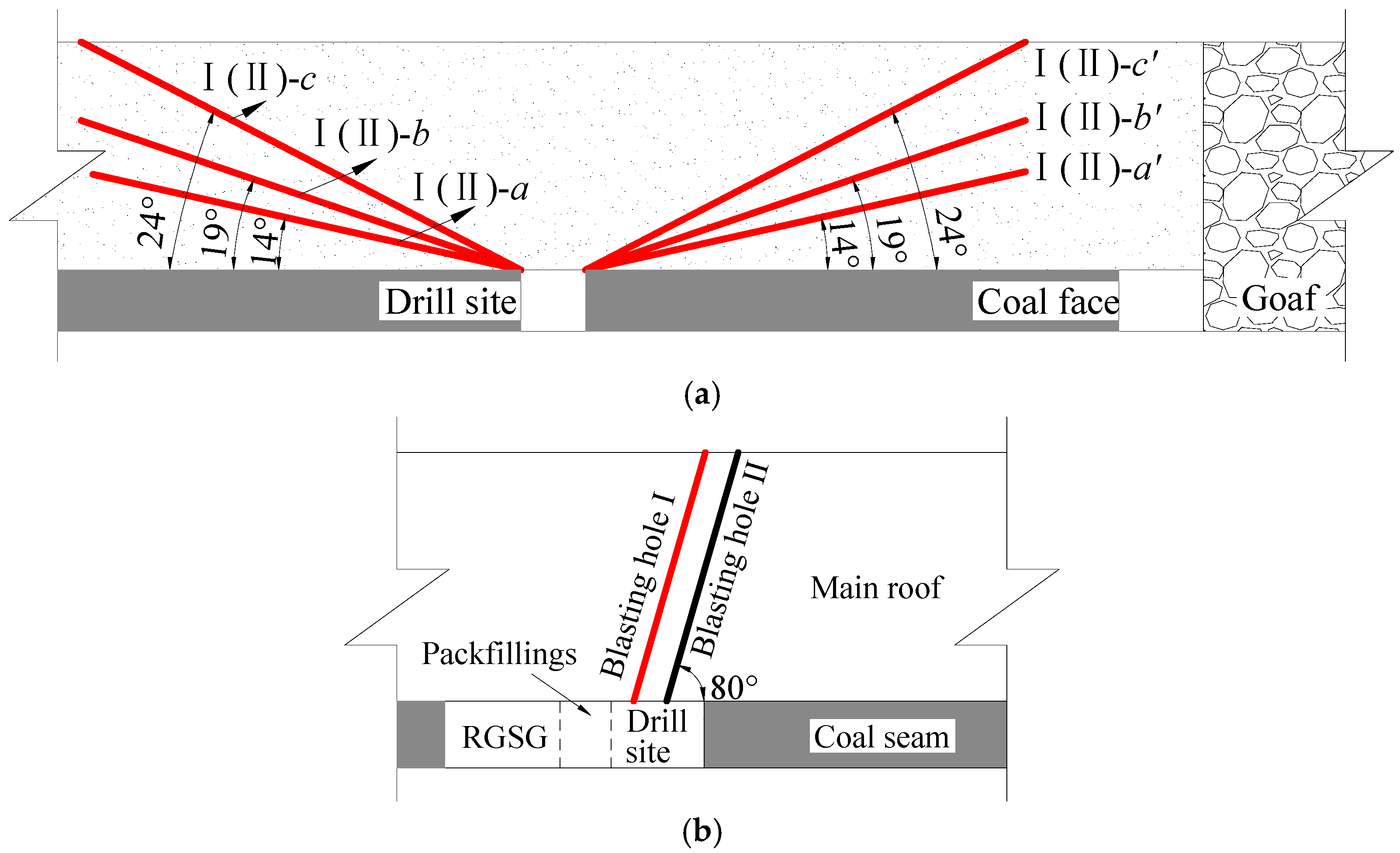
Pingdingshan No. 12 colliery is located in Pingdingshan city, Henan Province, China. Its mineable coal seam is buried at an average depth of 1100 m, with an average thickness of 2.0 m. The immediate roof is sandstone with an average thickness of 18 m and an average Protodikonov’s Hardness Coefficient of more than 7.3. A roof cantilever with a large length is expected to form over the RGSG after coal-seam mining. To reduce severer influence of the long roof cantilever movement on the RGSG, pre-split blasting technology was applied to make artificial cracks along the outer side of packfillings before coal seam is mined. After coalface passes by, this hard roof could cave along the pre-split, the length of roof cantilever could be shortened considerably, and the corresponding influence on the RGSG stability could be eliminated. Distribution of blasting holes in drill site is illustrated in Figure 18.
Twelve blasting holes were drilled in every site. Three blasting holes (a, b and c (red lines)) were drilled backward coalface with vertical inclined angle of 14°, 19° and 24° and horizontal rotational range of 4°, 7° and 10°, respectively. Another three blasting holes (a’, b’ and c’ (red lines)) with same parameters were drilled toward coalface. To crack the hard sandstone thoroughly and to ensure the effectiveness of stress relief, additional one set of blasting holes (black lines) with same parameters were also drilled in one drill site. The beginning position of charge was located more than 3 m vertically and 5 m horizontally away from the blasting hole opening to eliminate the adverse influence of blasting on the roadway stability. The blasting charge was professional mine water-gel explosive.
After application of the above technologies, the RGSG convergence of packfillings was less 145 mm and the roof sag was no more than 131 mm, and the roadway residual section area was larger than 10 m2, and it could be reused during the adjacent coal panel mining. The final profiles of the roadway before and after roof pre-split are shown in Figure 19.
5. Conclusions and Recommendations
In China, coal provides most of the energy for the development of economy and industrialization. Mining depth is increasing quickly due to large production and limited coal resources in shallow depth. How to exploit the valuable coal resources in deep underground more efficiently and safely not only affects the sustainable development of resources and energy, but also influences the sustainable development of economy and society in China, as well as the whole world. In this paper, stability of the RGSG being able to increase coal recovery rate and reduce gas accumulation and pollution is selected as the research target. Several contents including roof structure, stress and deformation evolution, roadway stability controlling technology and field verification are presented. The main conclusions in this paper are listed as follows.
- (1)
- As a result of rock strata movement over the goaf, a roof cantilever forms over the RGSG that is located at the side of goaf. The sinking and rotation movement of the roof cantilever weakens the rock surrounding the RGSG. This effect increases as the main roof becomes thicker and the immediate roof becomes thinner.
- (2)
- The influence of the abutment stress induced by coal seam mining on the RGSG can be divided into three stages: no influence more than 40 m ahead of the coalface or more than 120 m behind the coalface; slight influence 20–40 m ahead of the coalface or 60–120 m behind the coalface; and strong influence from 20 m ahead of the coalface to 60 m behind the coalface. These stresses produce large deformations in the rock that surrounds the roadway. As the thickness of the main roof increases and the thickness of the immediate roof decreases, these deformations increase considerably during the coal-panel mining. The maximum deformation of the rock surrounding the RGSG occurs when the RGSG is directly beneath the hard main roof of 12 m thickness.
- (3)
- Staged support technology involving conventional cable bolts cannot maintain the long-term stability of a deep RGSG. Roadway space enlarging including floor dinting and sidewall expanding has to be carried out because of large deformations before the second coal panel mining. Grout cable bolts can improve the flexibility of the deep RGSG by reducing the size of the plastic zone in the surrounding rock through providing large pull-put resistance and injection of grouts in the cracked surrounding rock. Roof structure optimizing technology involving pre-split can effectively improve the stability of the RGSG under hard roof strata by shortening the length of the hard roof cantilever.
Actually, the stress distribution around a stope in underground longwall mining system is also influenced by other factors including mining depth, mining height, retreating speed of coalface, backfilling level of excavations and so on. In the next stage, the authors will continue studying the influence of these factors on the RGSG stability. Moreover, tendency of the underground coalmining in China is transferring gradually from the East to the West where the environment is more fragile because of desertification and the coal seam is characterized by large thickness and shallow buried depth. Stability maintenance of the RGSG with slice mining method in thick coal seam and environmentally friendly construction material of artificial packfillings should also be considered in future study.
Acknowledgments
This research was sponsored by JSPS KAKENHI Grant Number 15H02332 and State Scholarship Fund from China Scholarship Council (CSC). We also thank Dalia Lahav-Jones, from Liwen Bianji, Edanz Group China for editing the English text of a draft of this manuscript.
Author Contributions
All of the authors contributed extensively to the work. Zhiyi Zhang proposed key ideas and wrote the manuscript. Hideki Shimada contributed to the data analysis. Takashi Sasaoka and Akihiro Hamanaka modified the manuscript.
Conflicts of Interest
The authors declare no conflict of interest.
References
- Huang, J.; Tian, C.; Xing, L.; Bian, Z.; Miao, X. Green and Sustainable Mining: Underground Coal Mine Fully Mechanized Solid Dense Stowing-Mining Method. Sustainability 2017, 9, 1418. [Google Scholar] [CrossRef]
- Trubetskoy, K.N.; Ruban, A.D.; Zaburdyaev, V.S. Characteristics of methane release in highly productive coal mines. J. Min. Sci. 2011, 47, 467–475. [Google Scholar] [CrossRef]
- Li, S.; Shuang, H.; Wang, H.; Song, K.; Liu, L. Extraction of Pressurized Gas in Low Air-Conductivity Coal Seam Using Drainage Roadway. Sustainability 2017, 9, 223. [Google Scholar] [CrossRef]
- David, R.G.; Rafael, J. A probabilistic extension to the empirical ALPS and ARMPS systems for coal pillar design. Int. J. Rock Mech. Min. Sci. 2012, 52, 181–187. [Google Scholar]
- Zhang, N.; Zhang, N.; Esterle, J.; Kan, J.G.; Zhao, Y.M.; Xue, F. Optimization of gateroad layout under a remnant chain pillar in longwall undermining based on pressure bulb theory. Int. J. Min. Reclam. Environ. 2016, 30, 128–144. [Google Scholar] [CrossRef]
- Yuan, L. Gas distribution of the mined-out side and extraction technology of first mined key seam relief-mining in gassy multi-seams of low permeability. J. China Coal Soc. 2008, 33, 1362–1367. [Google Scholar]
- Yang, W.; Lin, B.Q.; Yan, Q.; Zhai, C. Stress redistribution of longwall mining stope and gas control of multi-layer coal seams. Int. J. Rock Mech. Min. Sci. 2014, 72, 8–15. [Google Scholar] [CrossRef]
- Peng, S.S.; Chiang, H.S. Longwall Mining; Wiley: New York, NY, USA, 1984. [Google Scholar]
- Qian, D.; Shimada, H.; Zhang, Z.; Sasaoka, T.; Matsui, K. Application of goaf-side roadway retained and new type ventilation system in deep longwall face. Mem. Fac. Eng. Kyushu Univ. 2015, 74, 100–116. [Google Scholar]
- Feng, X.; Zhang, N. Position-optimization on retained entry and backfilling wall in gob-side entry retaining techniques. Int. J. Coal Sci. Technol. 2015, 2, 186–195. [Google Scholar] [CrossRef]
- Tan, Y.Y.; Yu, F.H.; Ning, J.G.; Zhao, T.B. Design and construction of entry retaining wall along a gob side under hard roof stratum. Int. J. Rock Mech. Min. Sci. 2015, 77, 115–121. [Google Scholar] [CrossRef]
- Zhang, Z.; Bai, J.; Chen, Y.; Yan, S. An innovative approach for gob-side entry retaining in highly gassy fully-mechanized longwall top-coal caving. Int. J. Rock Mech. Min. Sci. 2015, 80, 1–11. [Google Scholar] [CrossRef]
- Wang, H.; Zhang, D.; Liu, L.; Guo, W.; Fan, G.; Song, K.; Wang, X. Stabilization of gob-side entry with an artificial side for sustaining mining work. Sustainability 2016, 8, 627. [Google Scholar] [CrossRef]
- Ning, J.; Wang, J.; Bu, T.; Hu, S.; Liu, X. An innovative support structure for gob-side entry retention in steep coal seam mining. Minerals 2017, 7, 75. [Google Scholar] [CrossRef]
- Brown, E.T.; Hoek, E. Trends in relationships between measured in-situ stresses and depth. Int. J. Rock Mech. Min. Sci. 1978, 15, 211–215. [Google Scholar] [CrossRef]
- Yang, S.Q.; Xu, P.; Ranjith, P.G. Evaluation of creep mechanical behavior of deep-buried marble under triaxial cyclic loading. Arab. J. Geosci. 2014, 8, 6567–6582. [Google Scholar] [CrossRef]
- Itasca Consulting Group Inc. FLAC3D (Fast Lagrangian Analysis of Continua in 3 Dimensions); Version 3.1 User’s Manual; Itasca Consulting Group Inc.: Minneapolis, MN, USA, 2002. [Google Scholar]
- Yan, S.; Bai, J.B.; Wang, X.; Huo, L. An innovative approach for gateroad layout in highly gassy longwall top coal caving. Int. J. Rock Mech. Min. Sci. 2013, 59, 33–41. [Google Scholar] [CrossRef]
- Bai, J.B. Surrounding Rock Control of Entry Driven Along Nest Goaf; Press of China University of Mining and Technology: Xuzhou, China, 2006; pp. 22–36. [Google Scholar]
- Utsuki, S. In-situ experimental studies on improvement of deformability of rock masses by grout treatment. Int. J. JSRM 2013, 9, 7–8. [Google Scholar]
- Zolfaghari, A.; Sohrabi Bidar, A.; Maleki Javan, M.R.; Haftani, M.; Mehinrad, A. Evaluation of rock mass improvement due to cement grouting by Q-system at Bakhtiary dam site. Int. J. Rock Mech. Min. Sci. 2015, 74, 38–44. [Google Scholar] [CrossRef]
Figure 1.
3D view of the: U type gateroads layout (a); and Y type gateroads layout (b) in longwall mining.
Figure 1.
3D view of the: U type gateroads layout (a); and Y type gateroads layout (b) in longwall mining.
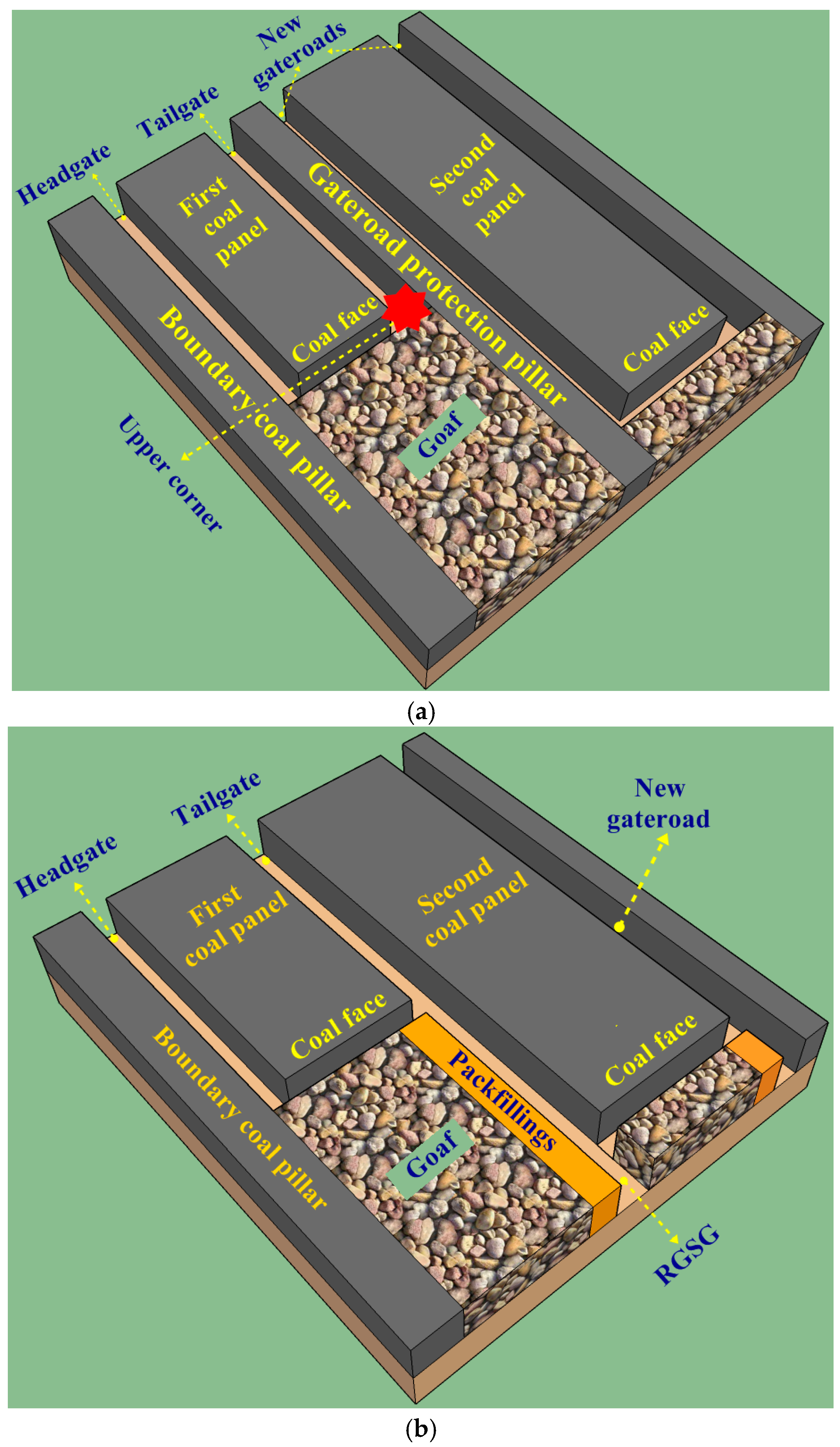
Figure 2.
Cross section of disturbed zones and abutment stress perpendicular to the advancing direction of the coalface.
Figure 2.
Cross section of disturbed zones and abutment stress perpendicular to the advancing direction of the coalface.
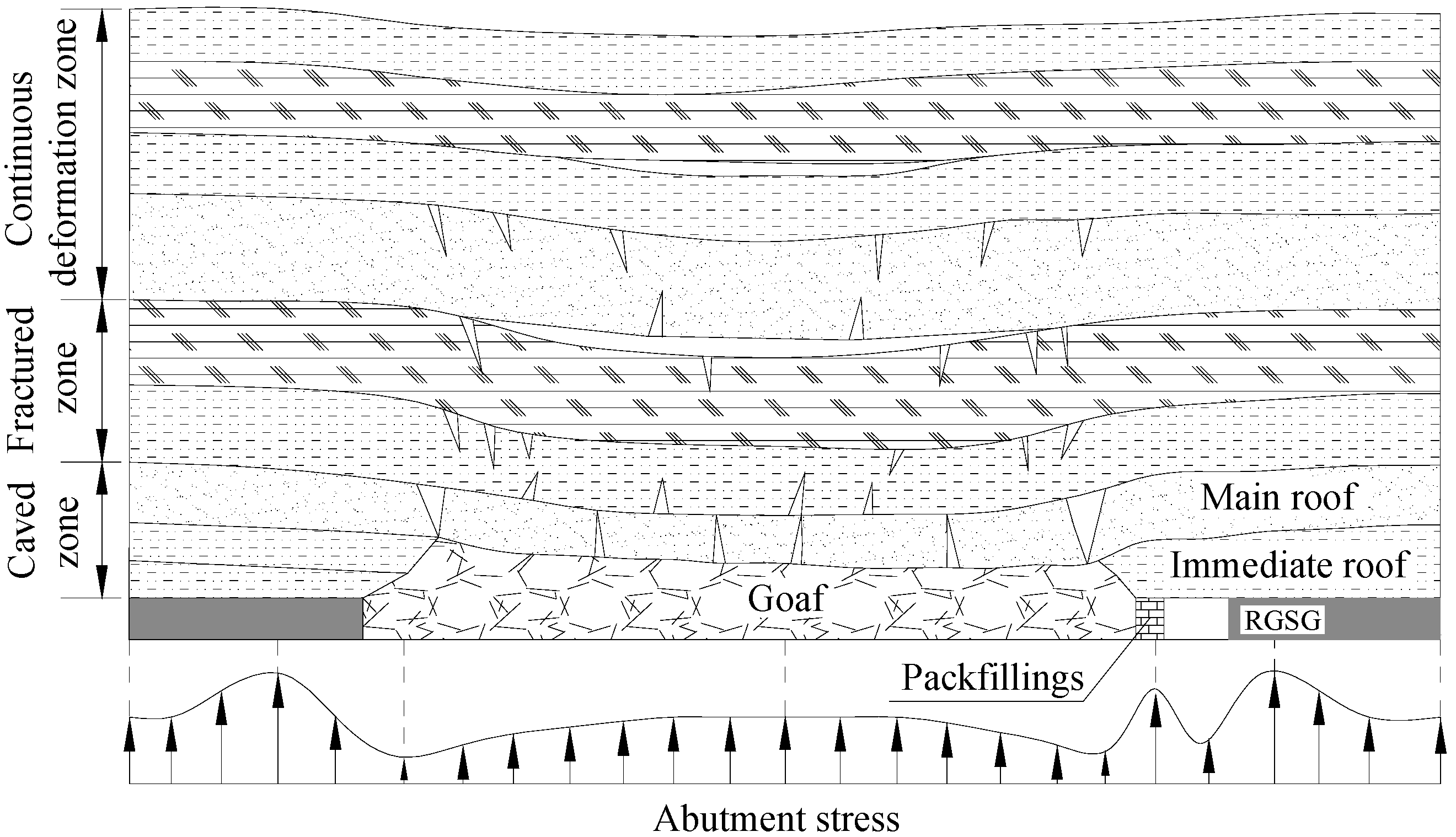
Figure 3.
Roof structure over the RGSG under different roof conditions: (a) thick immediate roof; (b) medium-thick immediate roof; (c) thin immediate roof; and (d) no immediate roof.
Figure 3.
Roof structure over the RGSG under different roof conditions: (a) thick immediate roof; (b) medium-thick immediate roof; (c) thin immediate roof; and (d) no immediate roof.

Figure 4.
3D view of the FLAC3D numerical model.

Figure 5.
Simulation method of the RGSG under different roof conditions.
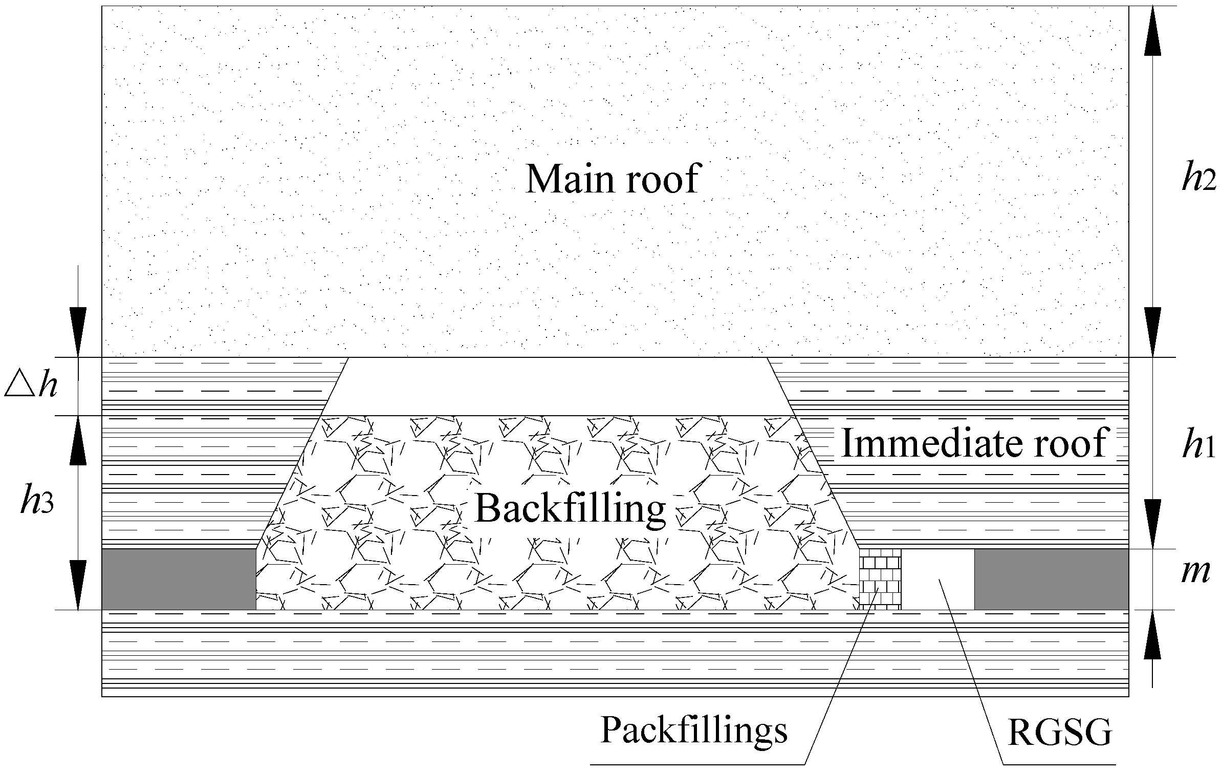
Figure 6.
(a) Simulation sequences and measuring station location; and (b) measuring detectors distribution.
Figure 6.
(a) Simulation sequences and measuring station location; and (b) measuring detectors distribution.

Figure 7.
Deformation curves of the rock surrounding the RGSG under different roof conditions during coal-seam mining: (a) roof; (b) floor; (c) left sidewall; and (d) right sidewall.
Figure 7.
Deformation curves of the rock surrounding the RGSG under different roof conditions during coal-seam mining: (a) roof; (b) floor; (c) left sidewall; and (d) right sidewall.
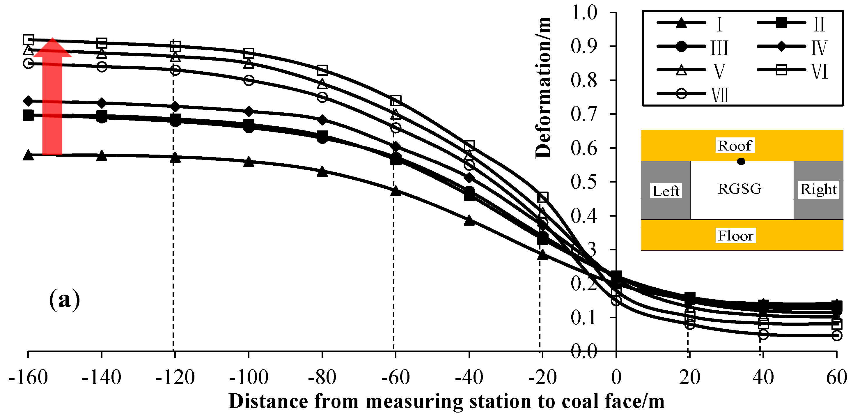
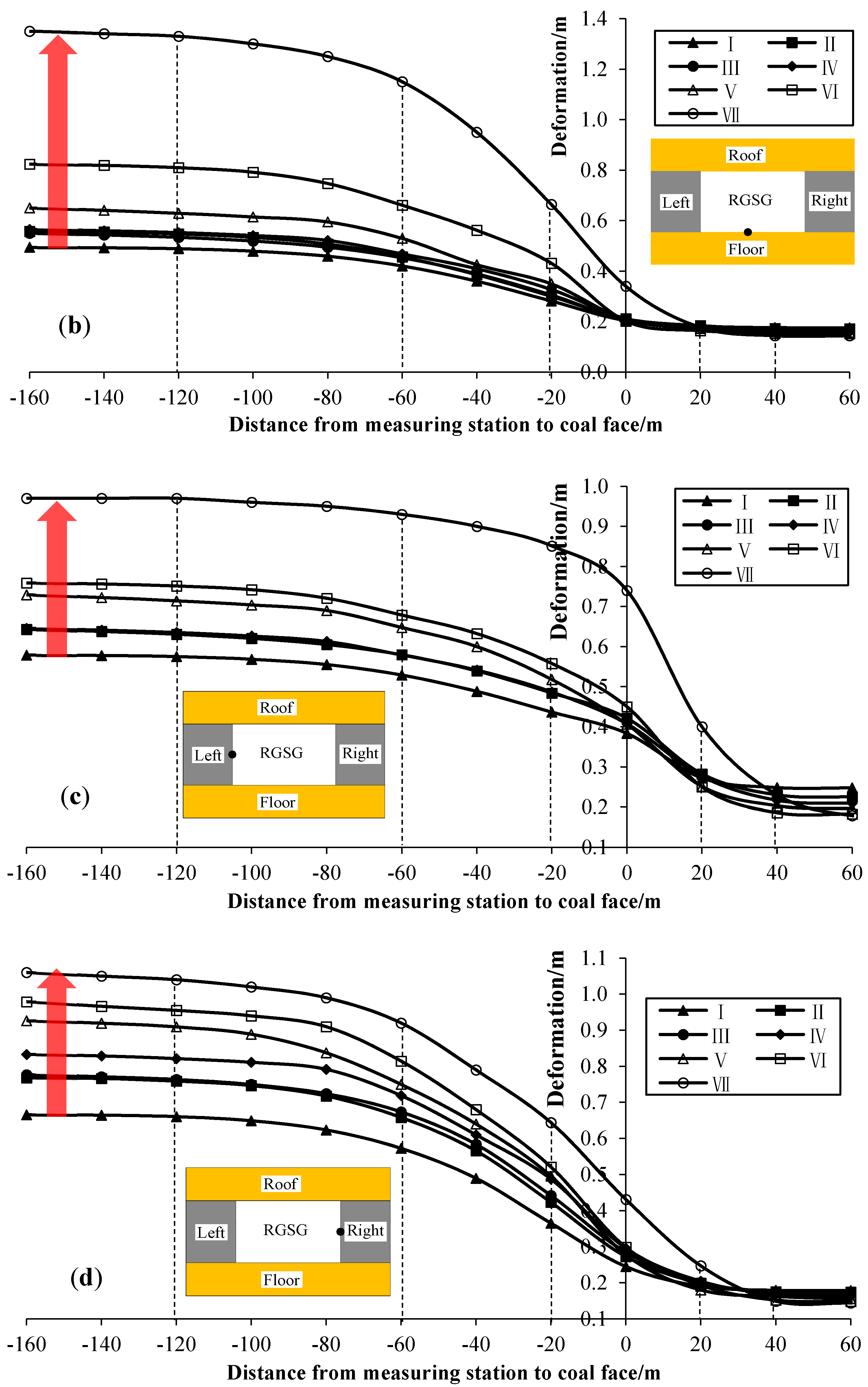
Figure 8.
Deformation contours of the rock surrounding the RGSG under different roof conditions: (a) roof condition I; (b) roof condition II; (c) roof condition III; (d) roof condition IV; (e) roof condition V; (f) roof condition VI; and (g) roof condition VII.
Figure 8.
Deformation contours of the rock surrounding the RGSG under different roof conditions: (a) roof condition I; (b) roof condition II; (c) roof condition III; (d) roof condition IV; (e) roof condition V; (f) roof condition VI; and (g) roof condition VII.

Figure 9.
Distribution of abutment stress in right sidewall at different distances to sidewall surface.
Figure 9.
Distribution of abutment stress in right sidewall at different distances to sidewall surface.

Figure 10.
Vertical stress in RGSG right sidewall under different roof conditions during coal-seam mining.
Figure 10.
Vertical stress in RGSG right sidewall under different roof conditions during coal-seam mining.

Figure 11.
(a) Geological columnar section; and (b) distribution of the staged RGSG support.

Figure 12.
(a) Support parameters in the first supporting stage; and (b) support parameters in the second supporting stage.
Figure 12.
(a) Support parameters in the first supporting stage; and (b) support parameters in the second supporting stage.

Figure 13.
Deformations curves of the RGSG surrounding rock during the first coal panel mining.
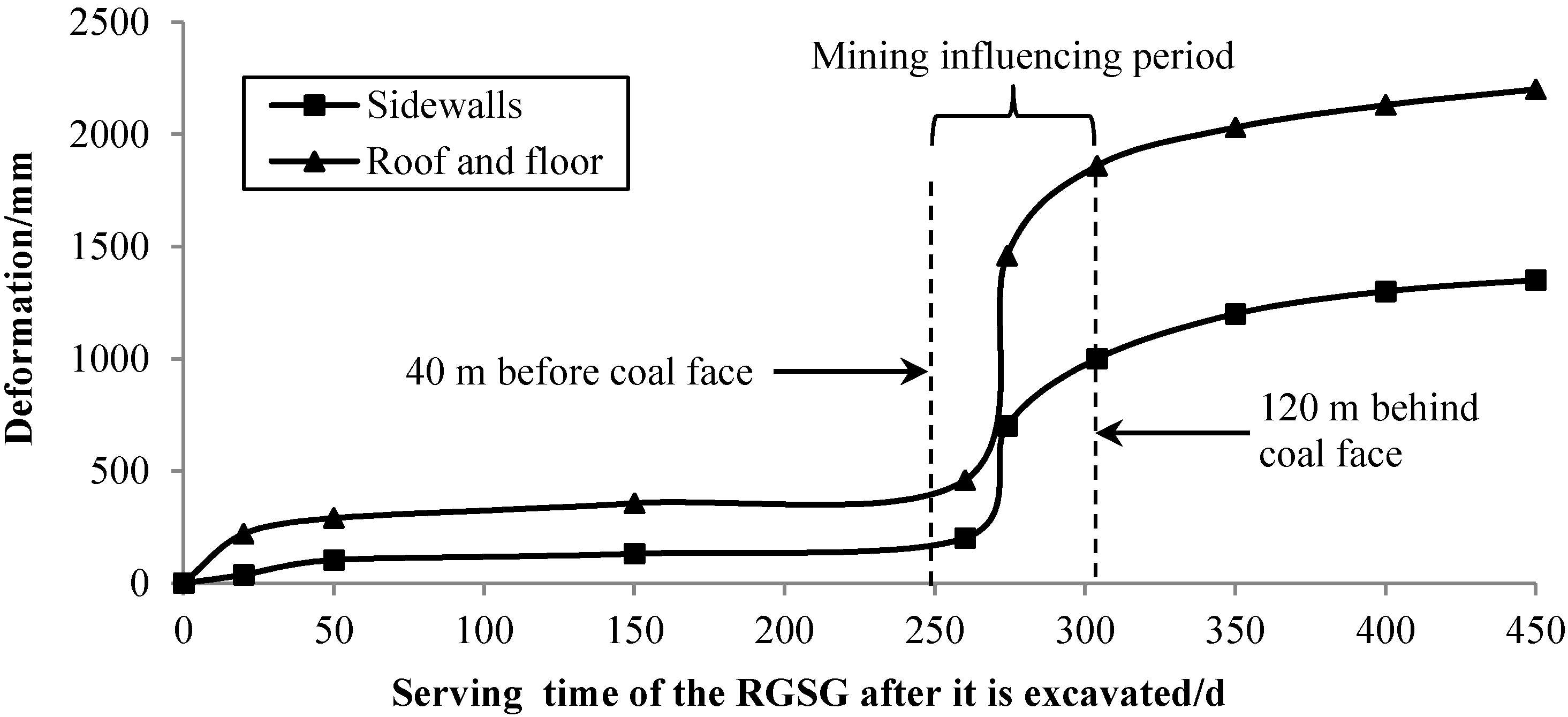
Figure 14.
Profiles of the RGSG in different mining stages: (a) after the first longwall panel mining; (b) during floor dinting; (c) during right sidewall expanding; and (d) before the second longwall panel mining.
Figure 14.
Profiles of the RGSG in different mining stages: (a) after the first longwall panel mining; (b) during floor dinting; (c) during right sidewall expanding; and (d) before the second longwall panel mining.

Figure 15.
Structure model of the RGSG behind the coalface.
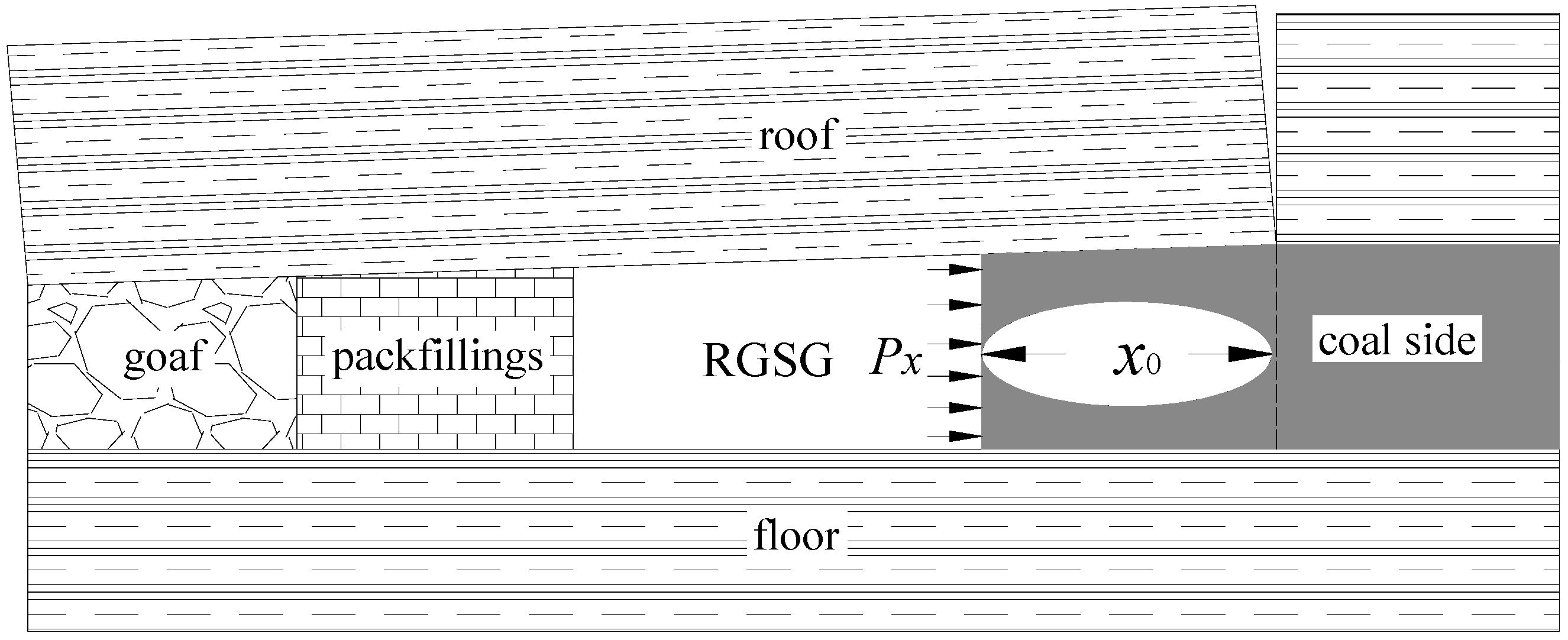
Figure 16.
Location (a); and installation parameters (b) of the grouting cable bolts in the RGSG in cross section I-I.
Figure 16.
Location (a); and installation parameters (b) of the grouting cable bolts in the RGSG in cross section I-I.

Figure 17.
Deformation curves of the rock surrounding the RGSG in Panyidong coalmine.
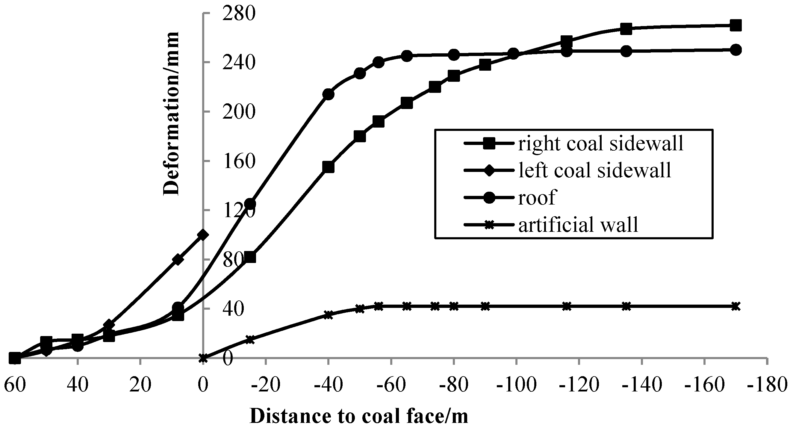
Figure 18.
Distribution of the blasting holes: (a) section view along RGSG axis; and (b) section view perpendicular to the RGSG axis.
Figure 18.
Distribution of the blasting holes: (a) section view along RGSG axis; and (b) section view perpendicular to the RGSG axis.

Figure 19.
Profile of the RGSG under hard roof: (a) before roof pre-split; and (b) after roof pre-split.
Figure 19.
Profile of the RGSG under hard roof: (a) before roof pre-split; and (b) after roof pre-split.

Table 1.
Thickness of rock strata in different simulation schemes.
| Roof Conditions | Thickness of Coal Seam m/m | Thickness of Immediate Roof h1/m | Thickness of Main Roof h2/m | Thickness of Backfilling h3/m | Subsidence of Main Roof Δh/m |
|---|---|---|---|---|---|
| I | 3.0 | 12.0 | 0 | 15.0 | 0 |
| II | 3.0 | 10.0 | 2.0 | 12.5 | 0.5 |
| III | 3.0 | 8.0 | 4.0 | 10.0 | 1.0 |
| IV | 3.0 | 6.0 | 6.0 | 7.5 | 1.5 |
| V | 3.0 | 4.0 | 8.0 | 5.0 | 2.0 |
| VI | 3.0 | 2.0 | 10.0 | 2.5 | 2.5 |
| VII | 3.0 | 0 | 12.0 | 0 | 3.0 |
Table 2.
Mechanics parameters of the rock strata used in simulation.
| Strata | Density | Bulk Modulus | Shear Modulus | Cohesion | Friction Angle |
|---|---|---|---|---|---|
| (kg/m3) | (GPa) | (GPa) | (MPa) | (°) | |
| Siltstone | 2600 | 3.03 | 1.84 | 1.5 | 28 |
| Mudstone | 2400 | 2.68 | 1.56 | Table 3 | Table 3 |
| Coal | 1450 | 1.19 | 0.37 | Table 3 | Table 3 |
| Sandstone | 2700 | 5.40 | 4.00 | 2.2 | 33 |
| Packfillings | 2500 | 4.50 | 3.00 | 2.0 | 30 |
Table 3.
Variations of the residual cohesion and friction angle versus plastic shear strain.
| Mechanical Parameters | Mudstone | Coal | ||
|---|---|---|---|---|
| Plastic shear strain | 0 | 0.1 | 0 | 0.1 |
| Cohesion/(MPa) | 1.2 | 0.12 | 0.8 | 0.08 |
| Friction angle/(°) | 27 | 24 | 23 | 20 |
© 2017 by the authors. Licensee MDPI, Basel, Switzerland. This article is an open access article distributed under the terms and conditions of the Creative Commons Attribution (CC BY) license (http://creativecommons.org/licenses/by/4.0/).
Share and Cite
MDPI and ACS Style
Zhang, Z.; Shimada, H.; Sasaoka, T.; Hamanaka, A. Stability Control of Retained Goaf-Side Gateroad under Different Roof Conditions in Deep Underground Y Type Longwall Mining. Sustainability 2017, 9, 1671. https://doi.org/10.3390/su9101671
AMA Style
Zhang Z, Shimada H, Sasaoka T, Hamanaka A. Stability Control of Retained Goaf-Side Gateroad under Different Roof Conditions in Deep Underground Y Type Longwall Mining. Sustainability. 2017; 9(10):1671. https://doi.org/10.3390/su9101671
Chicago/Turabian StyleZhang, Zhiyi, Hideki Shimada, Takashi Sasaoka, and Akihiro Hamanaka. 2017. "Stability Control of Retained Goaf-Side Gateroad under Different Roof Conditions in Deep Underground Y Type Longwall Mining" Sustainability 9, no. 10: 1671. https://doi.org/10.3390/su9101671
Note that from the first issue of 2016, this journal uses article numbers instead of page numbers. See further details here.