Analysis and Optimization of Entry Stability in Underground Longwall Mining

Abstract
:1. Introduction
2. Analysis of the Entry Stability in Conventional Mining Patterns
2.1. Numerical Analysis of the Entry Wall Stability
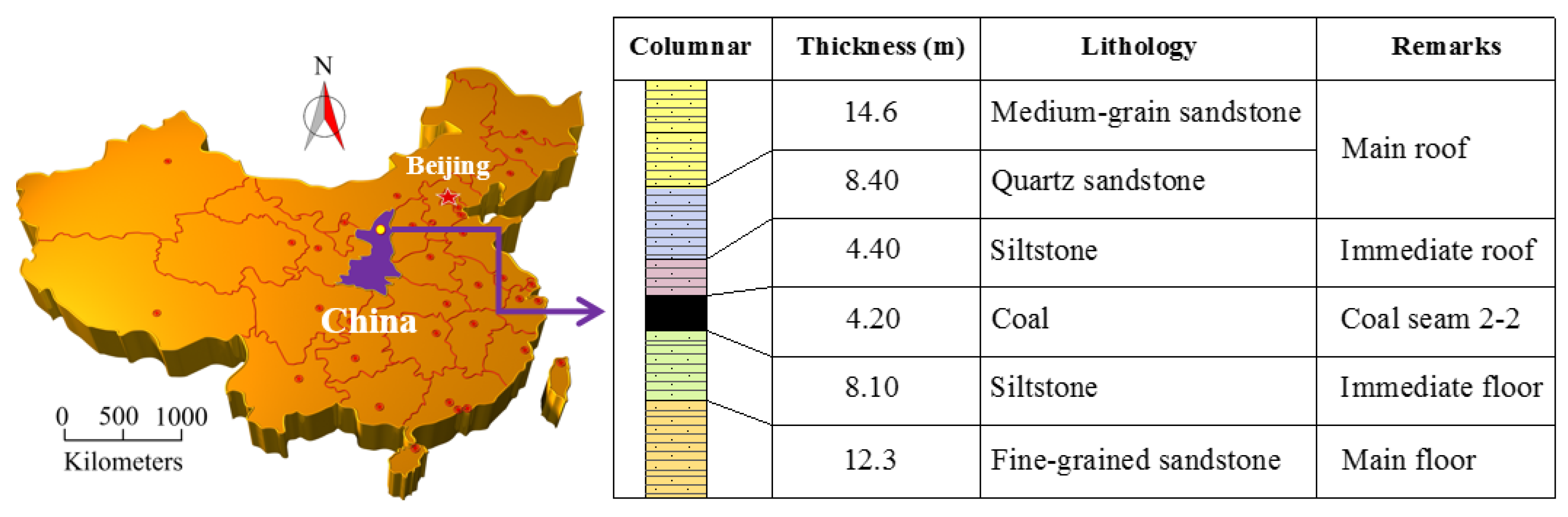
2.1.1. Study Site
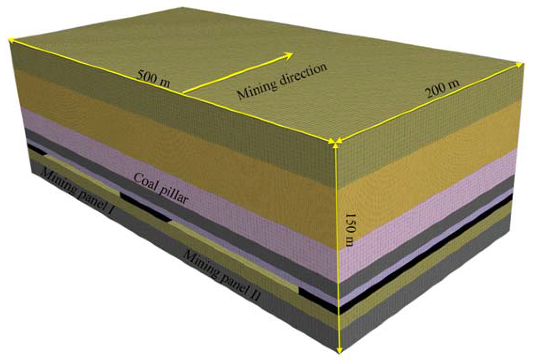
2.1.2. Numerical Model
2.1.3. Evolution Laws of the Vertical Stress on the Entry Wall
- (1).
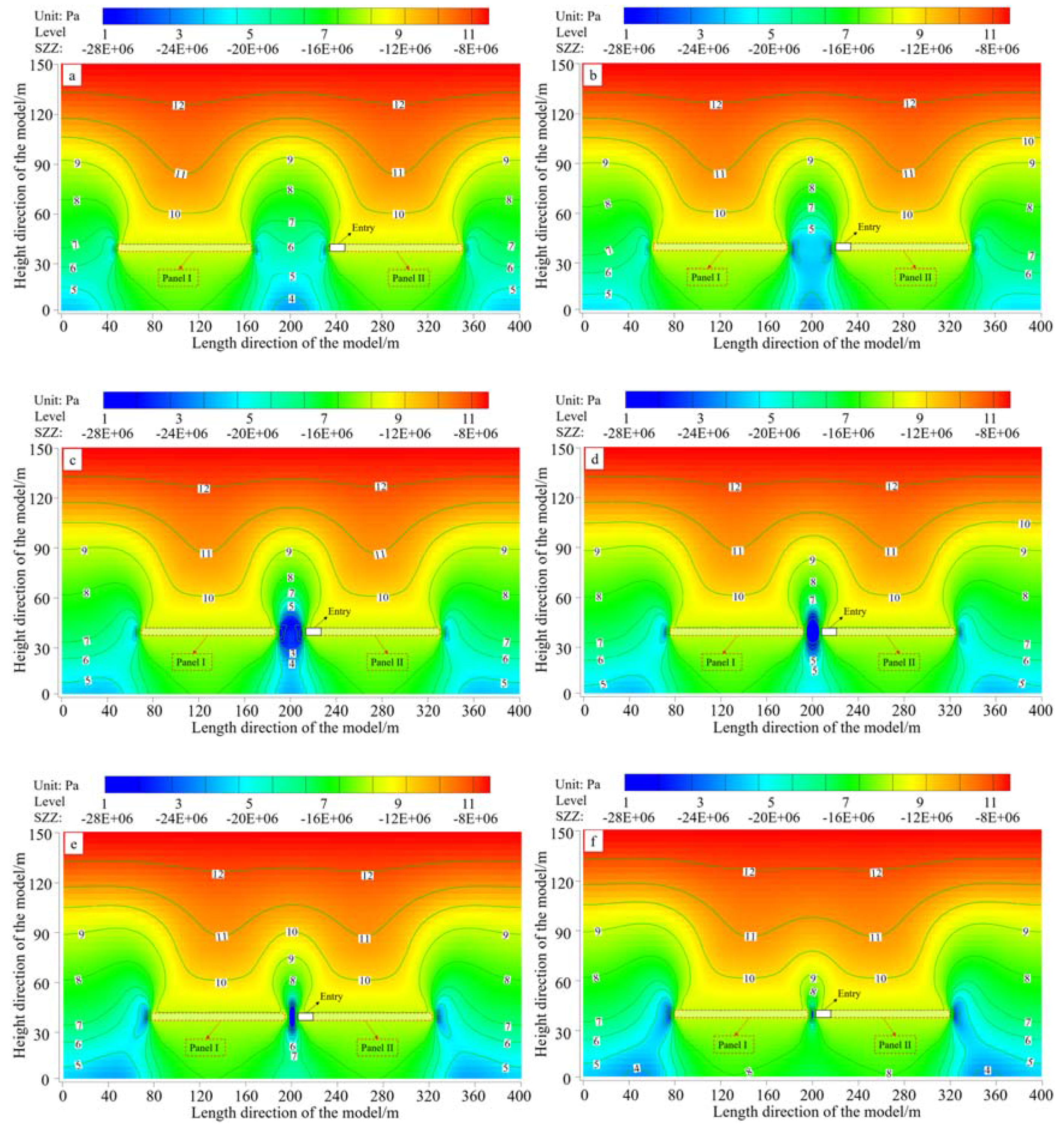
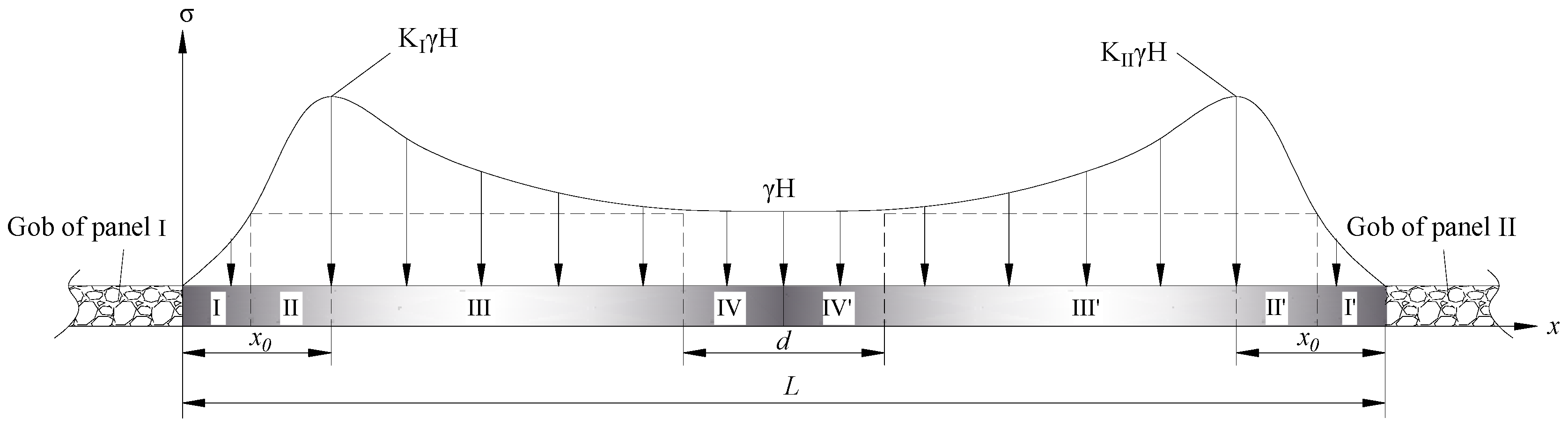
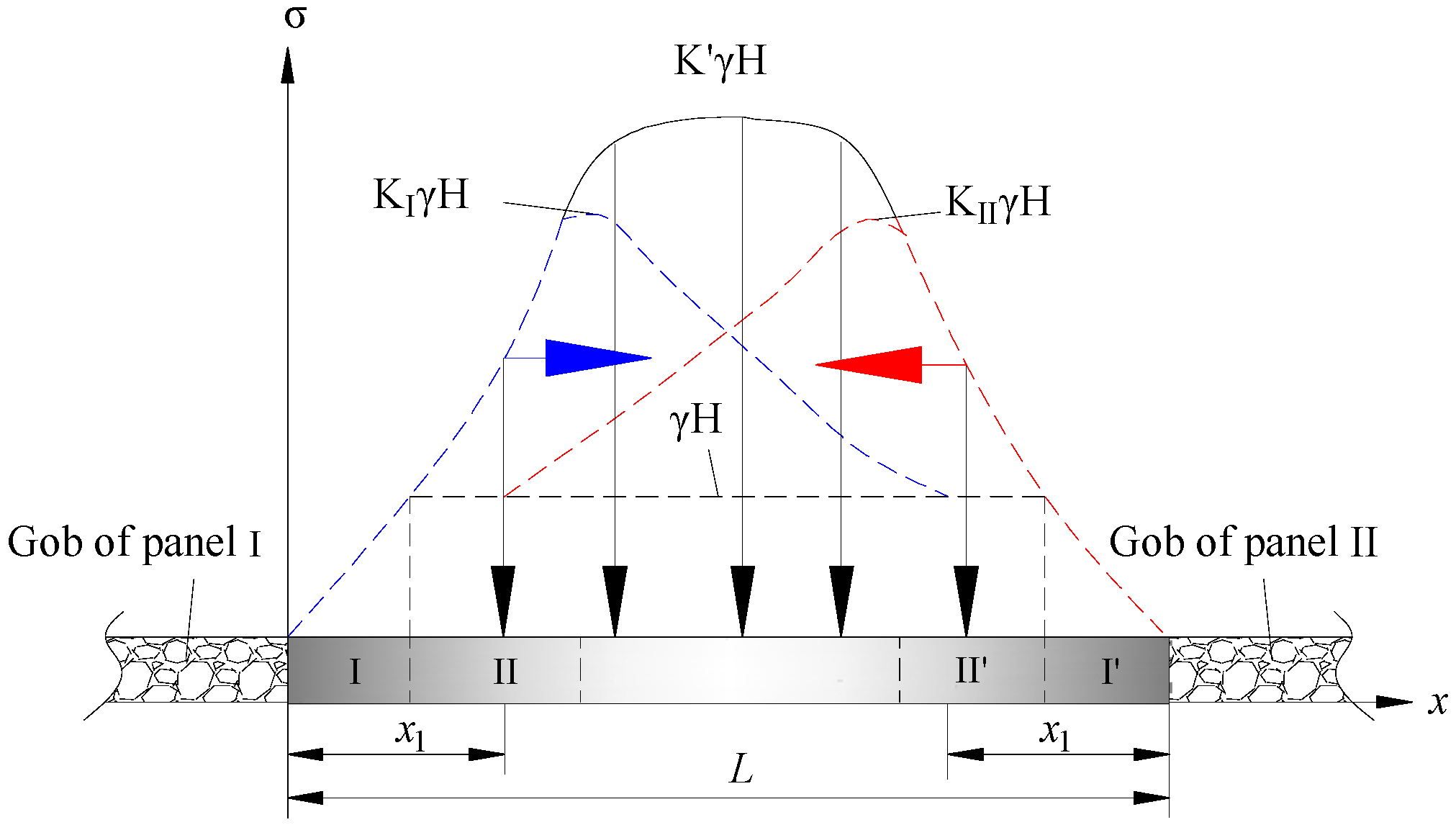
- In terms of stress migration, the stress peaks moved closer to each other as the pillar width decreased. The macroscopic shape of the vertical stress was double-arched when the pillar widths were large (80 m, 50 m and 30 m). Gradually, the double-arched shape of the stress evolved into a single-arched shape (15 m, 8 m and 5 m), and the integrated peak stress increased as well. In fact, the vertical stress on the pillar was induced in two stages. In the first stage, the stress was induced by the production of the present panel (panel I). After the surrounding rocks had stabilized, the mining-induced stress gradually reached equilibrium and remained constant. Subsequently, as panel II was mined, and an additional stress was then superimposed on the existing stress. Finally, the vertical stress achieved equilibrium on the entry wall.
- (2).
- In terms of the stress magnitudes, the position of the stress peak was in front of the panel. When the pillar width was more than 50 m, two stress peaks caused by panel I and II were distributed near the pillar sides. As the pillar width decreased, the central stress increased on the pillar, whereas the peak value remained unchanged (approximately 21.8 MPa). When the pillar widths were from 50 m to 30 m, there were also two stress peaks distributed on the two sides. However, the peak values increased quickly with decreasing pillar width. When the pillar width was less than 15 m, there was only one stress peak indicated macroscopically. The maximum vertical stress reached 27.8 MPa when the pillar width was 15 m. Interestingly, as the pillar width continued to decrease to 5 m, the peak stress decreased, as shown in Figure 3f. In a narrow pillar, there would be more mining-induced fractures distributed in the coal body. Essentially, the entry wall had been damaged. These fractures provided voids for the stress to release, causing the vertical stress to decrease.
2.2. Experimental Analysis of the Entry Wall Stability
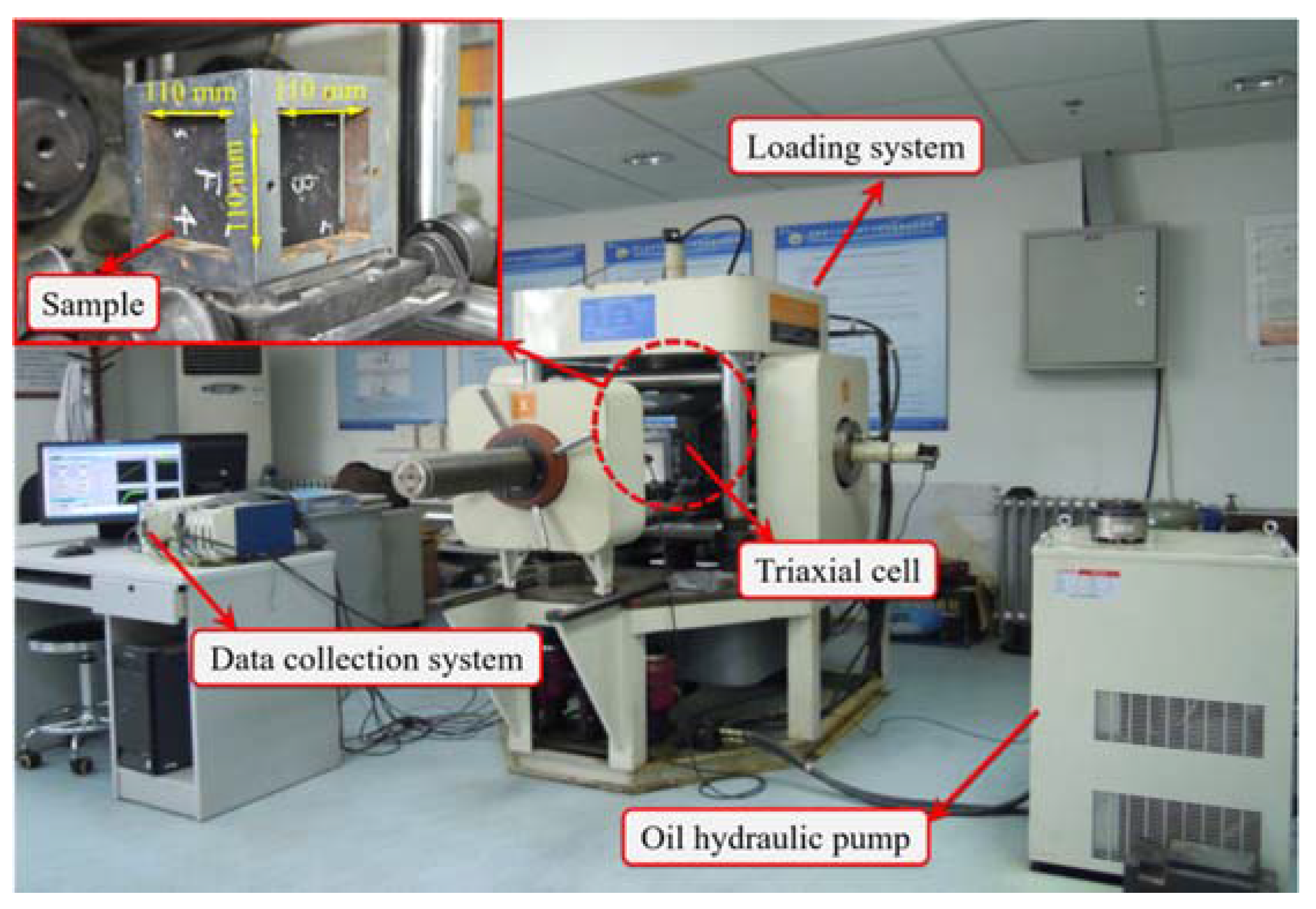
2.2.1. Model Description at the Laboratory
2.2.2. Methodology
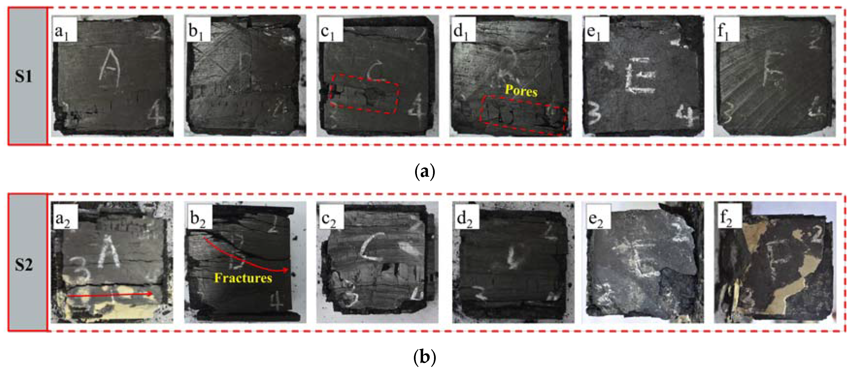
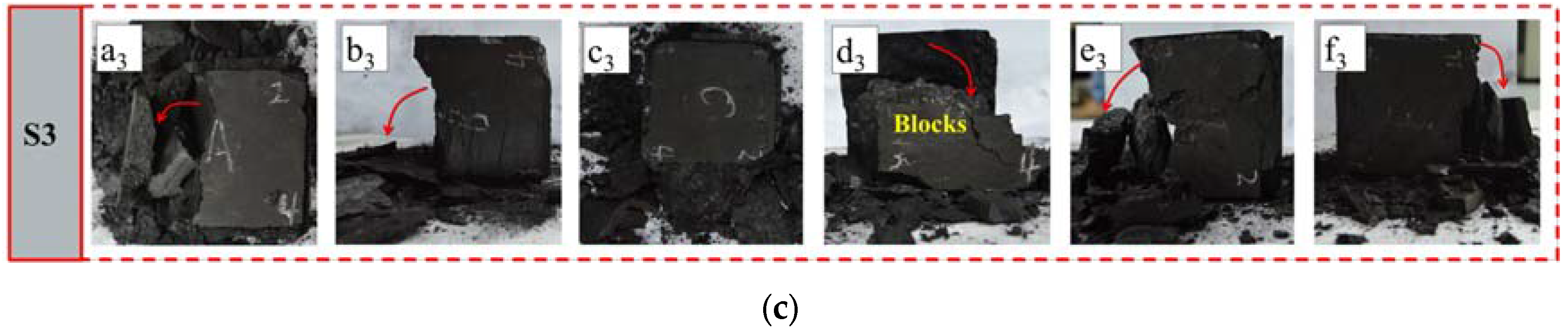
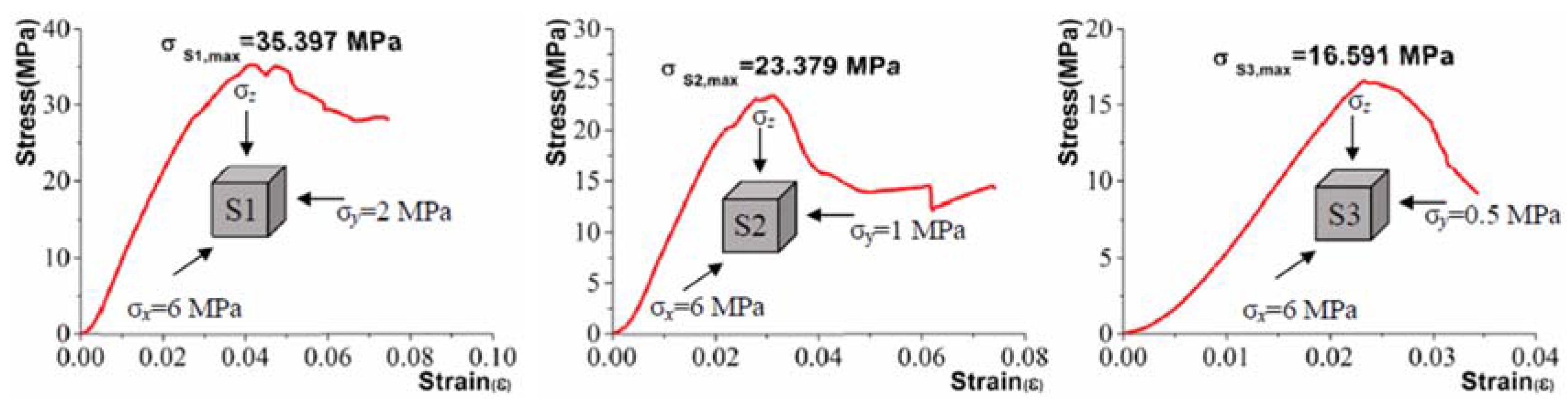
2.2.3. Test Results
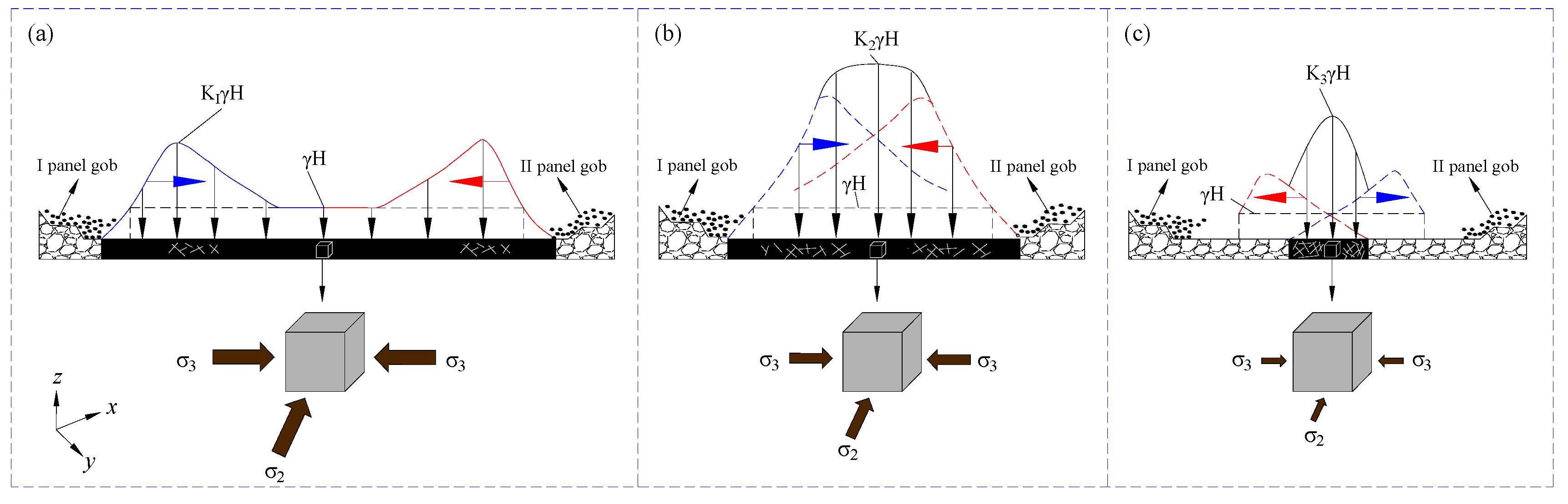
2.3. Theoretically Analysis of the Coal Pillar Stability
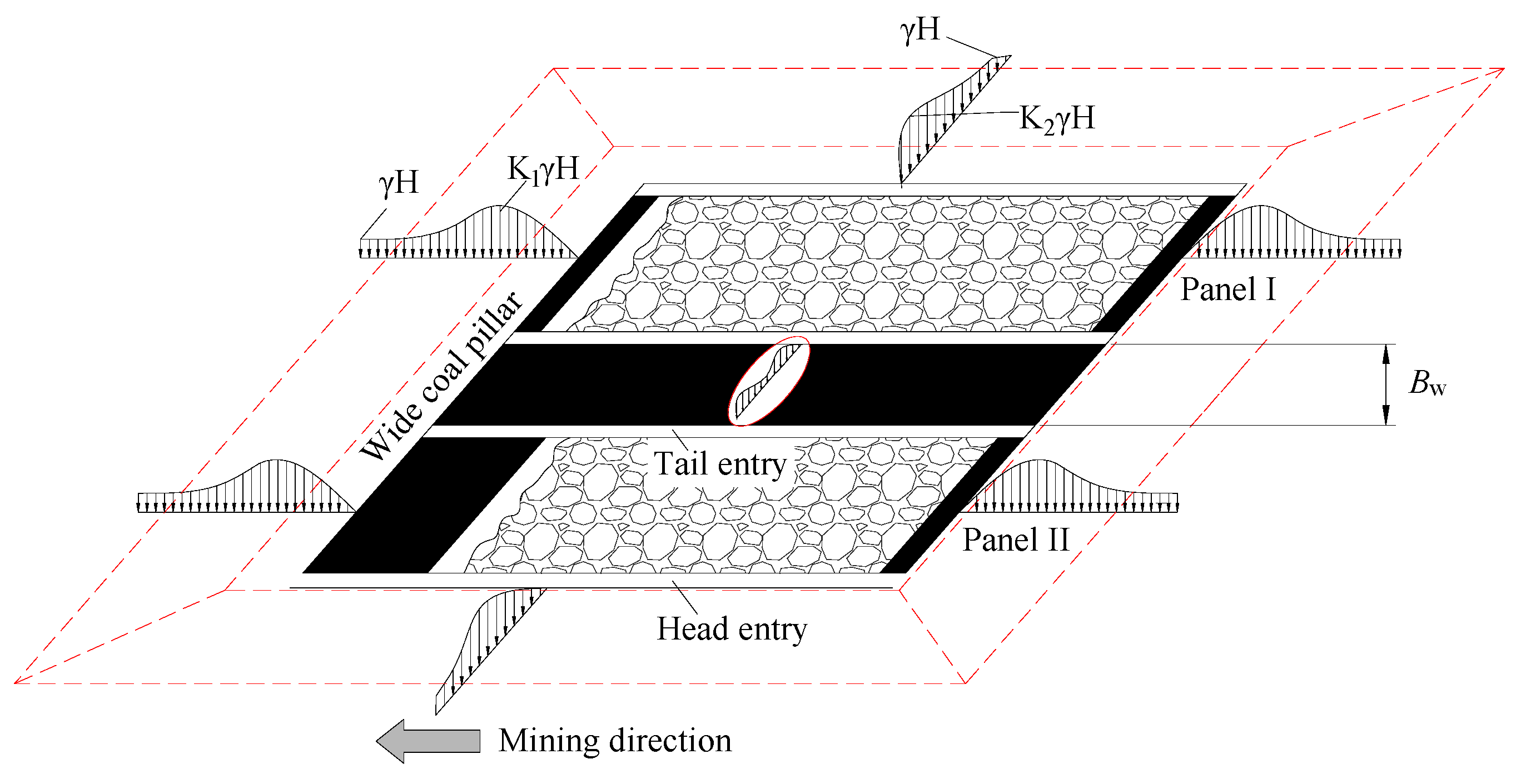
2.3.1. Wide Coal Pillar Mining
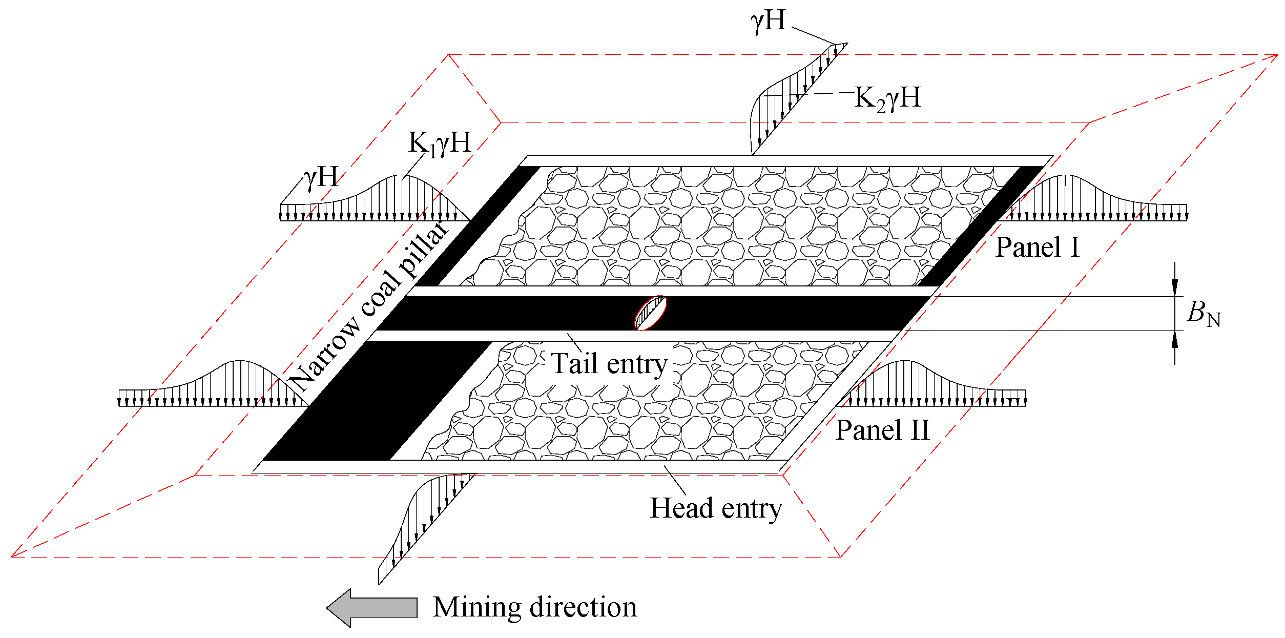
2.3.2. Narrow Coal Pillar Mining
2.3.3. Non-pillar Mining
3. Optimization of the Entry Stability in Longwall Mining
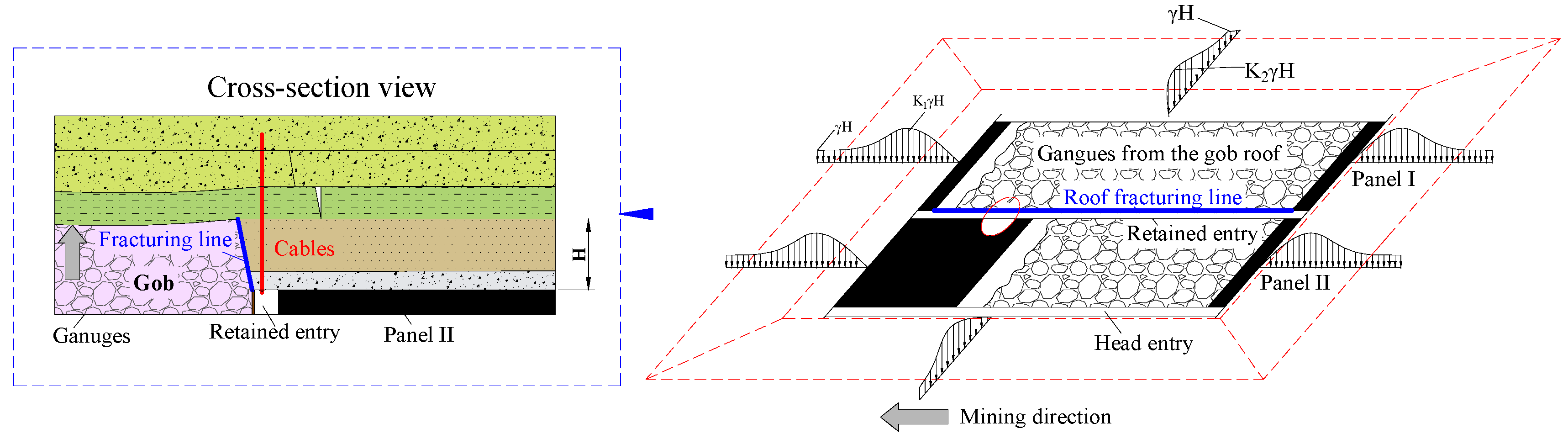
3.1. Directional Roof Fracturing (DRF) Technique
3.2. Stability Analysis of the Entry Using the Directional Roof Fracturing (DRF) Technique
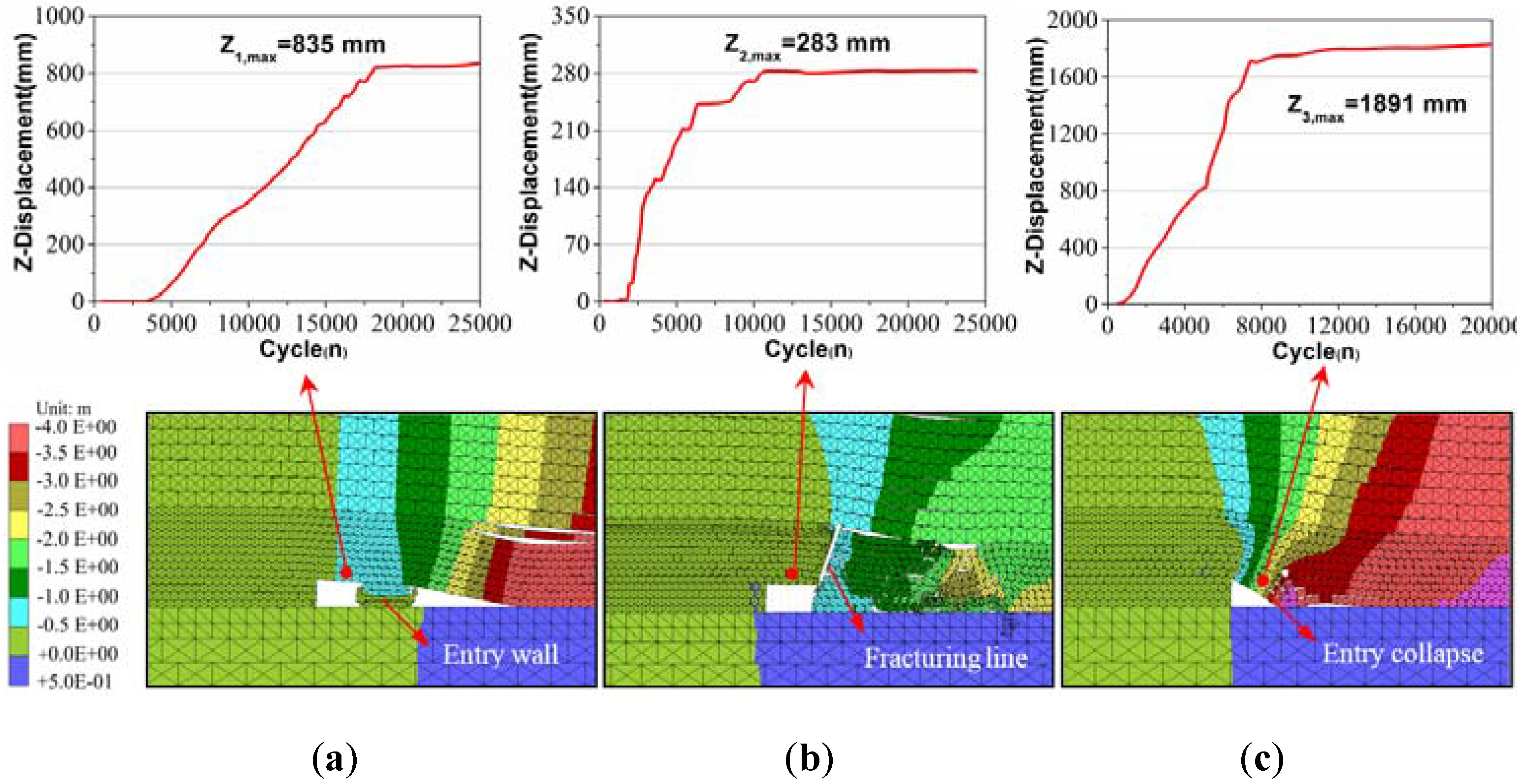
3.2.1. Numerical Simulation
3.2.2. Field Test
- (i)
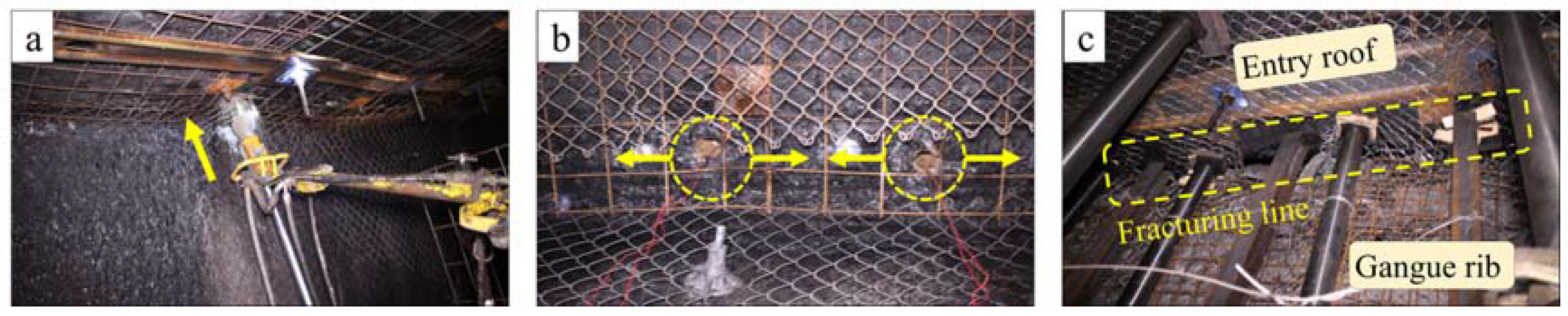
- Drill fracturing holes. The fracturing holes were marked on the roof in advance. The hole diameter and spacing were 46 mm and 600 mm, respectively. To reduce disturbances from the gob roof caving, the fracturing angle must be consistent, tilting ten degrees towards the mined-out area.
- (ii)
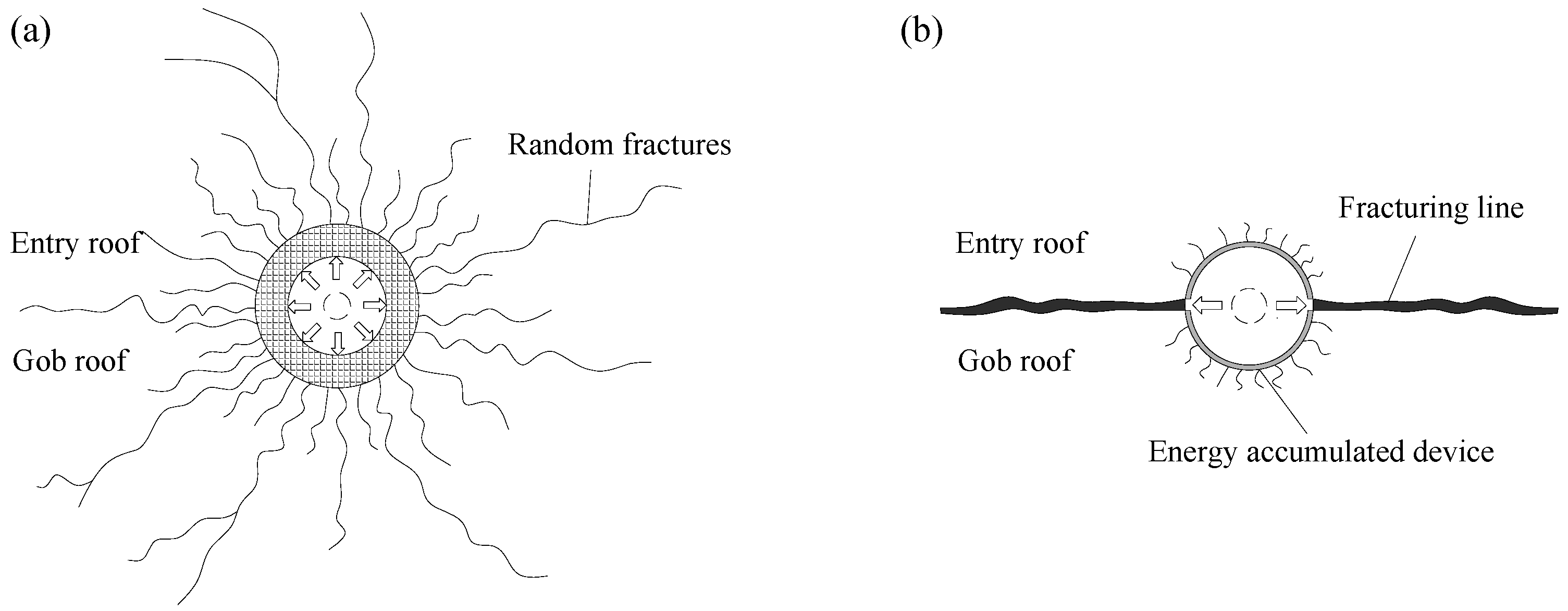
- Install energy binding tubes. First, the energy binding tubes were charged with emulsified blasting powders outside the fracturing holes. Subsequently, the tubes together with the powders were put into the holes. Note that the energy-accumulated direction must be same, in which case a continuous fracturing line could be formed.
- (iii)
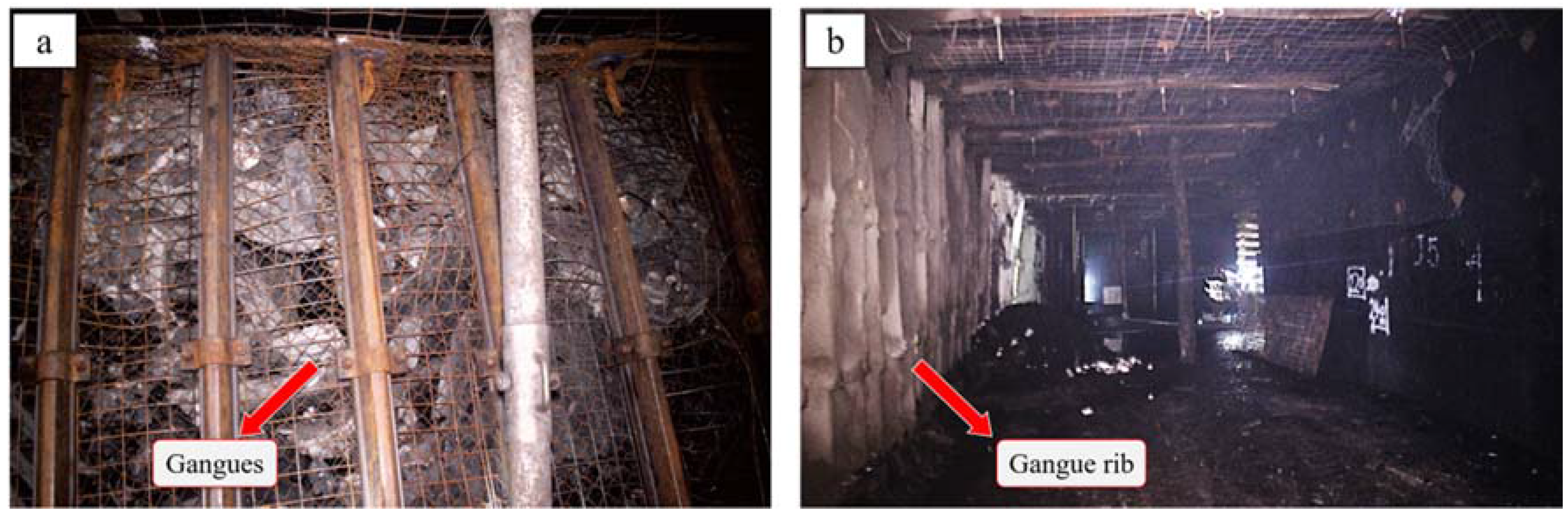
- Perform roof fracturing. After blasting, the cracks formed a fracturing line on the surface of the entry roof. As the mining panel advanced, the gob roof gradually caved along the fracturing line, and the caved gangues formed a special entry wall (gangue rib).
4. Conclusions
- (1)
- Simulations of different mining patterns showed that mining activities could cause stress concentrations on the entry wall. When the width of the entry wall was more than 30 m, there were two stress peaks distributed on the sides. As the width decreased, the stress peaks moved closer to each other and gradually merged into one. During this process, the vertical stresses caused by two mining panels, coupled with each other, and the integrated stress gradually increased. However, when the width was less than 10 m, the coupling stress decreased unexpectedly.
- (2)
- Entry wall stabilities were simply explored using representative coal units at the laboratory. True triaxial tests showed that, as the confining stress decreased, the critical buckling load decreased, and the degree of damage became more serious. The testing results implied that a wide pillar was more stable than a narrow one. Nevertheless, the serious waste of resources was a considerable concern for mining with wide coal pillars. Hence, mining with coal pillars always involves a tradeoff between economy and safety.
- (3)
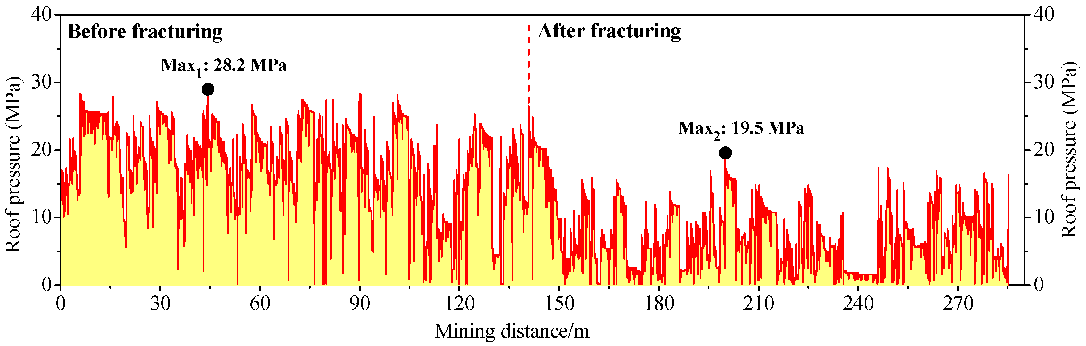
- Considering the existing problems of longwall mining with coal pillars, an innovative approach to improve entry stabilities by optimizing the stress distributions was introduced. In this approach, the geometry of the entry and gob roofs is actively controlled by roof fracturing along with support, thus reducing stress in the retained entry. Additionally, bulking characteristics of the caving gangues at the gob area are efficiently used, and no extra man-made filling material is therefore needed, which makes this approach more flexible and cost effective compared with other previous approaches. Numerical modeling showed that the DRF technique could prevent stress transfer from the gob roof to entry roof, thus causing the entry to be more stable. The deformation of the entry roof decreased by approximately 66% compared with that using the conventional mining method. Field tests indicated that the average roof pressure decreased by approximately 60% after adopting the new technique. Together, these results suggested that the DRF technique could not only avoid resource waste but also be favorable to improving entry stabilities.
Acknowledgments
Author Contributions
Conflicts of Interest
References
- Milici, R.C.; Flores, R.M.; Stricker, G.D. Coal resources, reserves and peak coal production in the United States. Int. J. Coal Geol. 2013, 113, 109–115. [Google Scholar] [CrossRef]
- Lechner, A.M.; Kassulke, O.; Unger, C. Spatial assessment of open cut coal mining progressive rehabilitation to support the monitoring of rehabilitation liabilities. Resour. Policy 2016, 50, 234–243. [Google Scholar] [CrossRef]
- Shabanimashcool, M.; Li, C.C. A numerical study of stress changes in barrier pillars and a border area in a longwall coal mine. Int. J. Coal Geol. 2013, 106, 39–47. [Google Scholar] [CrossRef]
- Suchowerska, A.M.; Merifield, R.S.; Carter, J.P. Vertical stress changes in multi-seam mining under supercritical longwall panels. Int. J. Rock Mech. Min. Sci. 2013, 61, 306–320. [Google Scholar] [CrossRef]
- Basarir, H.; Ferid Oge, I.; Aydin, O. Prediction of the stresses around main and tail gates during top coal caving by 3D numerical analysis. Int. J. Rock Mech. Min. Sci. 2015, 76, 88–97. [Google Scholar] [CrossRef]
- Su, D.W. Effects of longwall-induced stress and deformation on the stability and mechanical integrity of shale gas wells drilled through a longwall abutment pillar. Int. J. Min. Sci. Technol. 2017, 27, 115–120. [Google Scholar] [CrossRef]
- Gao, Y.; Liu, S.; Lyu, B.; Li, K. Mechanism study of floor water inrush around mining field based on micro-crack extension. J. Min. Saf. Eng. 2016, 33, 624–629. [Google Scholar]
- Cheng, G.; Ma, T.; Tang, C.; Liu, H.; Wang, S. A zoning model for coal mining—Induced strata movement based on microseismic monitoring. Int. J. Rock Mech. Min. Sci. 2017, 94, 123–138. [Google Scholar] [CrossRef]
- Tu, S.; Wang, F.; Dou, F.; Yuan, Y.; Lu, Y. Fully mechanized top-coal caving: Underground stress at gate ways under barrier pillars of an upper coal seam. J. China Univ. Min. Technol. 2010, 39, 1–5. [Google Scholar]
- Kang, H.; Wu, Y.; Gao, F. Deformation characteristics and reinforcement technology for entry subjected to mining-induced stresses. J. Rock Mech. Geotech. Eng. 2011, 3, 207–219. [Google Scholar] [CrossRef]
- Wei, G. Study on the width of the non-elastic zone in inclined coal pillar for strip mining. Int. J. Rock Mech. Min. Sci. 2014, 72, 304–310. [Google Scholar] [CrossRef]
- Wang, S.; Hao, S.; Chen, Y.; Bai, J.; Wang, X.; Xu, Y. Numerical investigation of coal pillar failure under simultaneous static and dynamic loading. Int. J. Rock Mech. Min. Sci. 2016, 84, 59–68. [Google Scholar] [CrossRef]
- Reed, G.; Mctyer, K.; Frith, R. An assessment of coal pillar system stability criteria based on a mechanistic evaluation of the interaction between coal pillars and the overburden. Int. J. Min. Sci. Technol. 2017, 27, 9–15. [Google Scholar] [CrossRef]
- Wattimena, R.K.; Kramadibrata, S.; Sidi, I.D.; Azizi, M.A. Developing coal pillar stability chart using logistic regression. Int. J. Rock Mech. Min. Sci. 2013, 58, 55–60. [Google Scholar] [CrossRef]
- Das, A.J.; Mandal, P.K.; Ghosh, C.N.; Sinha, A. Extraction of locked-up coal by strengthening of rib pillars with FRP-A comparative study through numerical modelling. Int. J. Min. Sci. Technol. 2017, 27, 261–267. [Google Scholar] [CrossRef]
- Yang, J.; Yu, S.; Tao, Z.; Sun, X.; Wang, D. On the deformation and failure characteristics of the tertiary soft rock entry and coupling control measures. J. Min. Saf. Eng. 2014, 31, 373–378. [Google Scholar]
- He, M.; Gao, Y.; Yang, J.; Guo, Z.; Wang, E.; Wang, Y. An energy-gathered roof cutting technique in no-pillar mining and its impact on stress variation in surrounding rocks. Chin. J. Rock Mech. Eng. 2017, 36, 1314–1325. [Google Scholar]
- Zhang, N.; Yuan, L.; Han, C.; Xue, J.; Kan, J. Stability and deformation of surrounding rock in pillarless gob-side entry retaining. Saf. Sci. 2012, 50, 593–599. [Google Scholar] [CrossRef]
- Islavath, S.R.; Deb, D.; Kumar, H. Numerical analysis of a longwall mining cycle and development of a composite longwall index. Int. J. Rock Mech. Min. Sci. 2016, 89, 43–54. [Google Scholar] [CrossRef]
- Shabanimashcool, M.; Li, C.C. Numerical modelling of longwall mining and stability analysis of the gates in a coal mine. Int. J. Rock Mech. Min. Sci. 2012, 51, 24–34. [Google Scholar] [CrossRef]
- Cheng, Y.; Wang, J.; Xie, G.; Wei, W. Three-dimensional analysis of coal barrier pillars in tailgate area adjacent to the fully mechanized top caving mining face. Int. J. Rock Mech. Min. Sci. 2010, 47, 1372–1383. [Google Scholar] [CrossRef]
- Cai, M.; He, M.; Liu, D. Rock Mechanics and Engineering; Science Press: Beijing, China, 2013; pp. 32–38. [Google Scholar]
- Wang, G.; Wu, M.; Wang, R.; Xu, H.; Song, X. Height of the mining-induced fractured zone above a coal face. Eng. Geol. 2017, 216, 140–152. [Google Scholar] [CrossRef]
- Jing, Y.; Armstrong, R.T.; Mostaghimi, P. Rough-walled discrete fracture network modelling for coal characterisation. Fuel 2017, 191, 442–453. [Google Scholar] [CrossRef]
- Su, F.; Itakura, K.; Deguchi, G.; Ohga, K. Monitoring of coal fracturing in underground coal gasification by acoustic emission techniques. Appl. Energy 2017, 189, 142–156. [Google Scholar] [CrossRef]
- Huang, Z.; Dai, X.; Dong, L. Buckling failures of reserved thin pillars under the combined action of in-plane and lateral hydrostatic compressive forces. Comput. Geotech. 2017, 87, 128–138. [Google Scholar] [CrossRef]
- Chen, S.; Guo, W.; Cheng, G.; Zhao, T. Research on creep supporting effect of deep strip pillar. J. Min. Saf. Eng. 2012, 29, 48–53. [Google Scholar]
- Song, Y.; Yang, X. Evolution characteristics of deformation and energy fields during coal pillar instability. J. Min. Saf. Eng. 2013, 30, 822–827. [Google Scholar]
- Gu, S.; Jiang, B.; Wang, C.; Li, N. Simulation research on overburden failure and lead abutment pressure distribution of fully-mechanized sublevel caving face. Min. Res. Dev. 2013, 33, 11–14. [Google Scholar]
- Zhang, W.; Kong, X.; Kang, T.; Zhao, G. Research on reasonable size of large coal pillar between panels at mining face with soft surrounding rock. Min. Res. Dev. 2013, 33, 14–17. [Google Scholar]
- Zhang, Y.; Wan, Z.; Li, F.; Zhou, C.; Zhang, B.; Guo, F.; Zhu, C. Stability of coal pillar in gob-side entry driving under unstable overlying strata and its coupling support control technique. Int. J. Min. Sci. Technol. 2013, 23, 193–199. [Google Scholar] [CrossRef]
- Song, Z.; Cui, Z.; Xia, H.; Tang, J.; Wen, Z. The fundamental theoretical and engineering research on the green safe no coal pillar mining model by mainly using coal gangue backfill. J. China Coal Soc. 2010, 35, 705–710. [Google Scholar]
- Hou, C.; Li, X. Stability principle of big and small structures of rock surrounding entry driven along goaf in fully mechanized top coal caving face. J. China Coal Soc. 2001, 26, 1–7. [Google Scholar]
- Zhang, K.; Jiang, Y.; Zhang, Z.; Zhang, Y.; Pang, X.; Zeng, X. Determining the reasonable width of narrow pillar of entry in gob entry driving in the large pillar. J. Min. Saf. Eng. 2014, 31, 255–262. [Google Scholar]
- Wang, D.; Li, S.; Wang, Q.; Li, W.; Wang, F.; Wang, H.; Peng, P.; Ruan, G. Experimental study of reasonable coal pillar width in fully mechanized top coal caving face of deep thick coal seam. Chin. J. Rock Mech. Eng. 2014, 33, 539–548. [Google Scholar]
- Huang, Y.; Sun, H. Design of gob-side packing parameters for gateways maintained along the goaf. J. China Coal Soc. 1997, 22, 127–131. [Google Scholar]
- Zhang, J.; Li, B.; Zhou, N.; Zhang, Q. Application of solid backfilling to reduce hard-roof caving and longwall coal face burst potential. Int. J. Rock Mech. Min. Sci. 2016, 88, 197–205. [Google Scholar] [CrossRef]
- Zhang, Z.; Bai, J.; Chen, Y.; Yan, S. An innovative approach for gob-side entry retaining in highly gassy fully-mechanized longwall top-coal caving. Int. J. Rock Mech. Min. Sci. 2015, 80, 1–11. [Google Scholar] [CrossRef]
- Zhang, G.; He, M.; Yu, X.; Huang, Z. Research on the technique of no-pillar mining with gob-side entry formed by advanced roof caving in the protective seam in Baijiao coal mine. J. Min. Saf. Eng. 2011, 28, 511–516. [Google Scholar]
- Bu, T.; Feng, G.; Jia, K. Gateway side backfilling support technology of goaf side gateway in fully mechanized high cutting longwall mining face. Coal Sci. Technol. 2010, 38, 41–44. [Google Scholar]
- Ma, L.; Zhang, D.; Wang, H.; Li, Y. Mining technique with preset packing body in entry for thick coal seam without coal pillars. Chin. J. Rock Mech. Eng. 2010, 29, 674–680. [Google Scholar]
- Leclerc, W.; Haddad, H.; Guessasma, M. On the suitability of a Discrete Element Method to simulate cracks initiation and propagation in heterogeneous media. Int. J. Solids Struct. 2017, 108, 98–114. [Google Scholar] [CrossRef]
- Gui, Y.L.; Zhao, Z.Y.; Kodikara, J.; Bui, H.H.; Yang, S.Q. Numerical modelling of laboratory soil desiccation cracking using UDEC with a mix-mode cohesive fracture model. Eng. Geol. 2016, 202, 14–23. [Google Scholar] [CrossRef]
- Gao, Y.; Guo, Z.; Yang, J.; Wang, J.; Wang, Y. Steady analysis of gob-side entry retaining formed by roof fracturing and control techniques by optimizing mine pressure. J. China Coal Soc. 2017, 42, 1672–1681. [Google Scholar]


| Rock Strata | Density (kg/m3) | Elasticity Modulus (GPa) | Friction Angle (deg) | Cohesion (MPa) | Tensile Strength (MPa) |
|---|---|---|---|---|---|
| Overlying strata | 2500 | 15.2 | 30 | 1.8 | 0.7 |
| Fine sandstone | 2650 | 19.6 | 32 | 2.3 | 1.2 |
| Medium sandstone | 2600 | 13.5 | 34 | 2.4 | 1.4 |
| Quartz sandstone | 2780 | 21.1 | 38 | 3.2 | 1.6 |
| Siltstone | 2550 | 16.5 | 30 | 2.1 | 0.9 |
| No. 2-2 coal seam | 1250 | 4.3 | 19 | 0.9 | 0.4 |
| Siltstone | 2550 | 13.9 | 26 | 3.0 | 1.2 |
| Fine sandstone | 2650 | 18.8 | 33 | 3.1 | 1.5 |
| Sample | σz (Sample Faces) | σx (Sample Faces) | σ2 (MPa) | σy (Sample Faces) | σ3 (MPa) |
|---|---|---|---|---|---|
| S1 | A & C | (E & F) | 6.0 | (B & D) | 2.0 |
| S2 | A & C | (E & F) | 6.0 | (B & D) | 1.0 |
| S3 | A & C | (E & F) | 6.0 | (B & D) | 0.5 |
© 2017 by the authors. Licensee MDPI, Basel, Switzerland. This article is an open access article distributed under the terms and conditions of the Creative Commons Attribution (CC BY) license (http://creativecommons.org/licenses/by/4.0/).
Share and Cite
Gao, Y.; Liu, D.; Zhang, X.; He, M. Analysis and Optimization of Entry Stability in Underground Longwall Mining. Sustainability 2017, 9, 2079. https://doi.org/10.3390/su9112079
Gao Y, Liu D, Zhang X, He M. Analysis and Optimization of Entry Stability in Underground Longwall Mining. Sustainability. 2017; 9(11):2079. https://doi.org/10.3390/su9112079
Chicago/Turabian StyleGao, Yubing, Dongqiao Liu, Xingyu Zhang, and Manchao He. 2017. "Analysis and Optimization of Entry Stability in Underground Longwall Mining" Sustainability 9, no. 11: 2079. https://doi.org/10.3390/su9112079
APA StyleGao, Y., Liu, D., Zhang, X., & He, M. (2017). Analysis and Optimization of Entry Stability in Underground Longwall Mining. Sustainability, 9(11), 2079. https://doi.org/10.3390/su9112079