
Control of Thermally Activated Building System Considering Zone Load Characteristics


1
Department of Architecture and Architectural Engineering, Graduate School of Seoul National University, Seoul 08826, Korea
2
LG Hausys R&D Center, Anyang-si, Gyeonggi-do 14117, Korea
3
Department of Architecture and Architectural Engineering, College of Engineering, Seoul National University, Seoul 08826, Korea
4
Department of Architecture and Architectural Engineering, Institute of Construction and Environmental Engineering, Seoul National University, Seoul 08826, Korea
*
Author to whom correspondence should be addressed.
Sustainability 2017, 9(4), 586; https://doi.org/10.3390/su9040586
Submission received: 28 February 2017
/
Revised: 6 April 2017
/
Accepted: 6 April 2017
/
Published: 11 April 2017
(This article belongs to the Special Issue Sustainable and Resource–Efficient Homes and Communities)
Abstract
:The objectives of this study were to investigate the thermally activated building system (TABS) mechanism for appropriate use of the system and to apply the proper concept of TABS for each zone by using different TABS control strategies. In order to examine the TABS mechanism, dynamic simulation with EnergyPlus was used to model the office building with TABS, because the radiant heat exchange characteristics of the TABS according to the time variable was critical. The typical control concept of TABS, self-regulation, was applied in the simulation by setting the supply water temperature as room setpoint temperature. As a result, the advantage of self-regulation can be amplified by utilizing the entire thermal mass of the TABS, which can be executed by customizing to target a specific type of load. Since the large area of the office building may comprise different loads in different zones, the TABS control according to the different zone loads were proposed. By separating the control strategy from zone to zone, the proposed control strategy improved the thermal comfort by 5%, reduced peak heating load by 10%, reduced cooling load by 36%, and decrease the total energy consumption by 13%. This study demonstrated a possible improvement on self-regulation of TABS with separate zone controls.
1. Introduction
The indoor environment of a building should be maintained within an acceptable range that is comfortable for occupants. To achieve this, the indoor air temperature range is kept within a comfortable range by providing or removing heat according to the amount of heat loss or gain. This function is commonly provided by the heating and cooling system, which handles the loads by convective and radiant heat transfer. Conventional air conditioning systems were all-air systems that controlled the indoor air temperature using convective heat transfer. However, with increasing concerns about energy conservation, the recent trend is to utilize radiant heating and cooling systems that can improve the thermal comfort with higher mean radiant temperature for heating and lower mean radiant temperature for cooling [1,2]. Since these systems provide better thermal comfort, the acceptable comfort range of indoor air temperature may be increased and higher and lower setpoint temperatures might be used for cooling and heating, respectively. This reduces the heat transfer with the outdoor environment, and reduces heat loss and gain.
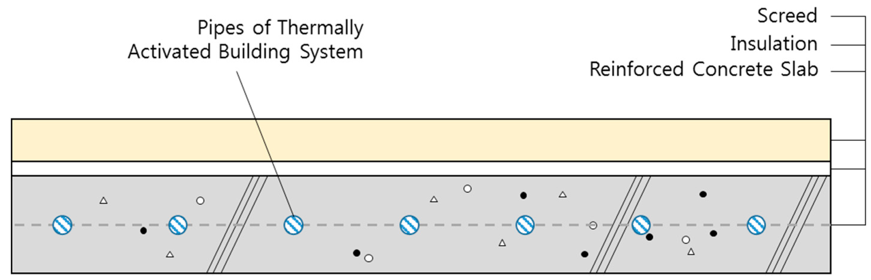
Among the many types of radiant heating and cooling systems, the thermally activated building system (TABS) has gained popularity. This system uses the concrete structure as a heating and cooling system by embedding pipes as demonstrated in Figure 1, which is proposed by ISO 11855 from the International Standard Organization (ISO) [3]. TABS consists of screed, insulation and reinforced concrete slab and insulation enables the system to handle the load occurred below the system. The embedding pipes in the concrete structure can reduce the installation, operation and maintenance costs. Moreover, the lack of additional installation allows reduction in the building height, which saves a significant amount of building materials [4]. Since the TABS exhibits characteristics of asynchrony of the plant operation and thermal load, the system can store heat in the concrete structure and shift the loads to a different time, which enables reduction of the peak load [5,6,7,8]. Consequently, the plant size can be reduced and made to operate with higher efficiency. However, the asynchrony of TABS operation and actual thermal output to the zone may raise difficulties related to the handling of dynamic and sudden loads. This is because changing the operation according to sudden zone changes takes time. Thermal inertia may continuously deliver heat into the zone, which will cause overheating or overcooling. For cooling, condensation should be considered and control may be a challenging issue [9,10]. Moreover, changes in different spaces may also cause difficulties in controlling the TABS. Appropriate heat should be supplied into a zone without causing overheating, overcooling or condensation.
Since the TABS has a time-delay between the operation and actual thermal output, overheating, overcooling and condensation can be avoided by applying the concept of self-regulation. Self-regulation in radiant systems is implemented by keeping the system temperature as the room setpoint temperature. Thus, when the heating load occurs, the room temperature will be lower than the setpoint temperature, and heat exchange between the room and the system will be triggered. A small change in room temperature will cause significant amount of radiant and convective heat exchange between the room and the system because the TABS has large area of radiant surface exposed to the room [9,11]. The concept can be explained with the following equation:
where q is the heat exchange between room and the system, hconv+rad is heat transfer coefficient of convection and radiation, Area is a surface area of the TABS exposed to the room, and TTABS is the system surface temperature and Ti is the indoor air temperature.
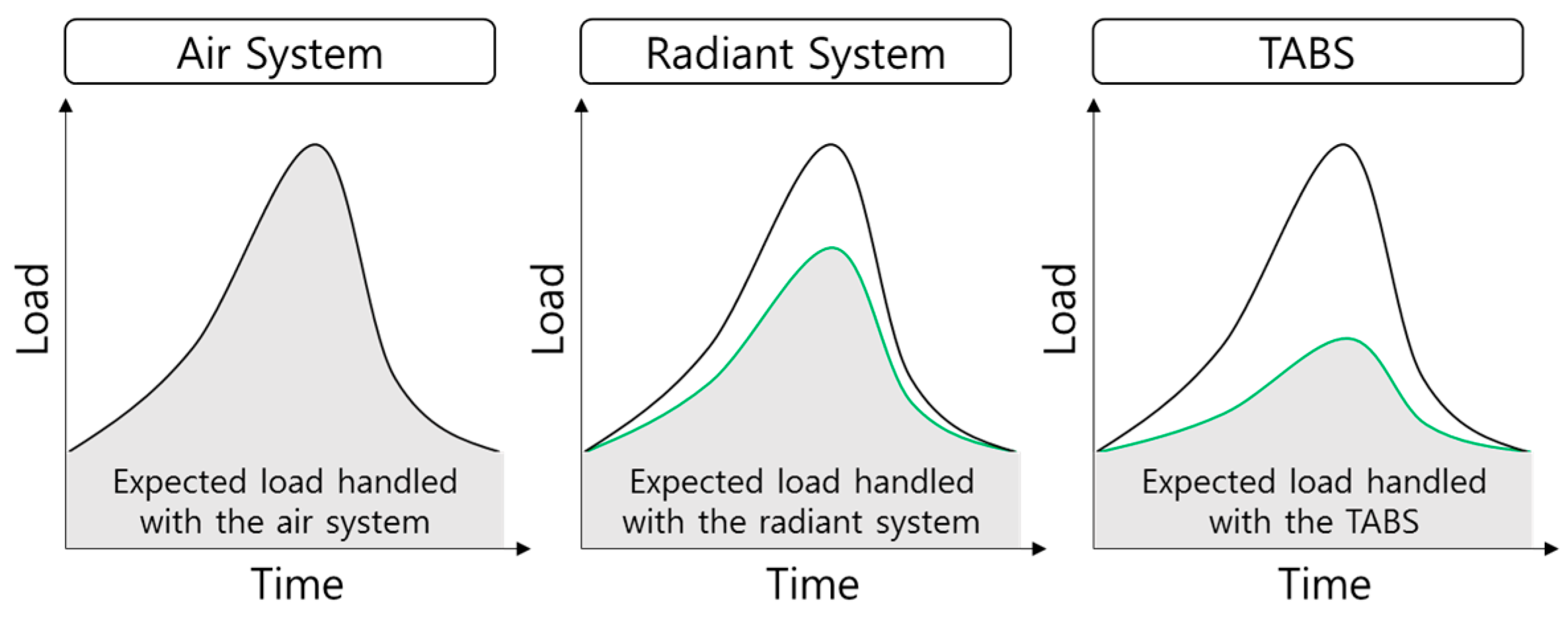
As the amount of load increases, the difference between the room temperature and system temperature will increase and more heat exchange will occur. The phenomenon of self-regulation for cooling is equivalent to that for heating. The main advantage of self-regulation is that the TABS can provide heating and cooling without considering the load that will occur. However, utilizing only self-regulation can provide limited amount of heat to the room, which will cause discomfort when a large load occurs [12]. Therefore, self-regulation is used with the TABS to handle the minimum expected heating and cooling loads in different zones. The remaining load is handled using an air system to ensure thermal comfort in the zone. The concept of design load handled with air system, radiant system and TABS is illustrated in Figure 2.
According to the Representatives of European Heating and Ventilating Associations (REHVA) guidelines, which are written by European experts on a number of related topics, when a building is well-designed and low and steady heating and cooling loads occur, a large portion of the loads may be handled using self-regulation [9]. However, actual heating and cooling loads of an office building are considerably large, because the occupants require an optimal thermal environment for increasing workability. Thus, the TABS can handle only a limited amount of heating and cooling loads in office buildings using self-regulation. Many previous studies attempted to remove the loads with the TABS as much as the expected load handled with the radiant system [13,14,15,16,17,18,19,20]. However, this paper focuses on the proper functioning of TABS. Hence, one of the objectives of this study is to investigate the ways to increase the load handled by the TABS by observing its working.
In order to increase the load handled by the system, the TABS must be customized to target a specific type of load. However, the large area of the office building may comprise different loads in different zones. The other objective of this study is to evaluate the possibility of using different control strategies for the TABS by considering different zone loads.
2. Analysis of Load Characteristics and Load Handled by the TABS
2.1. Application of Self-Regulation Using the TABS
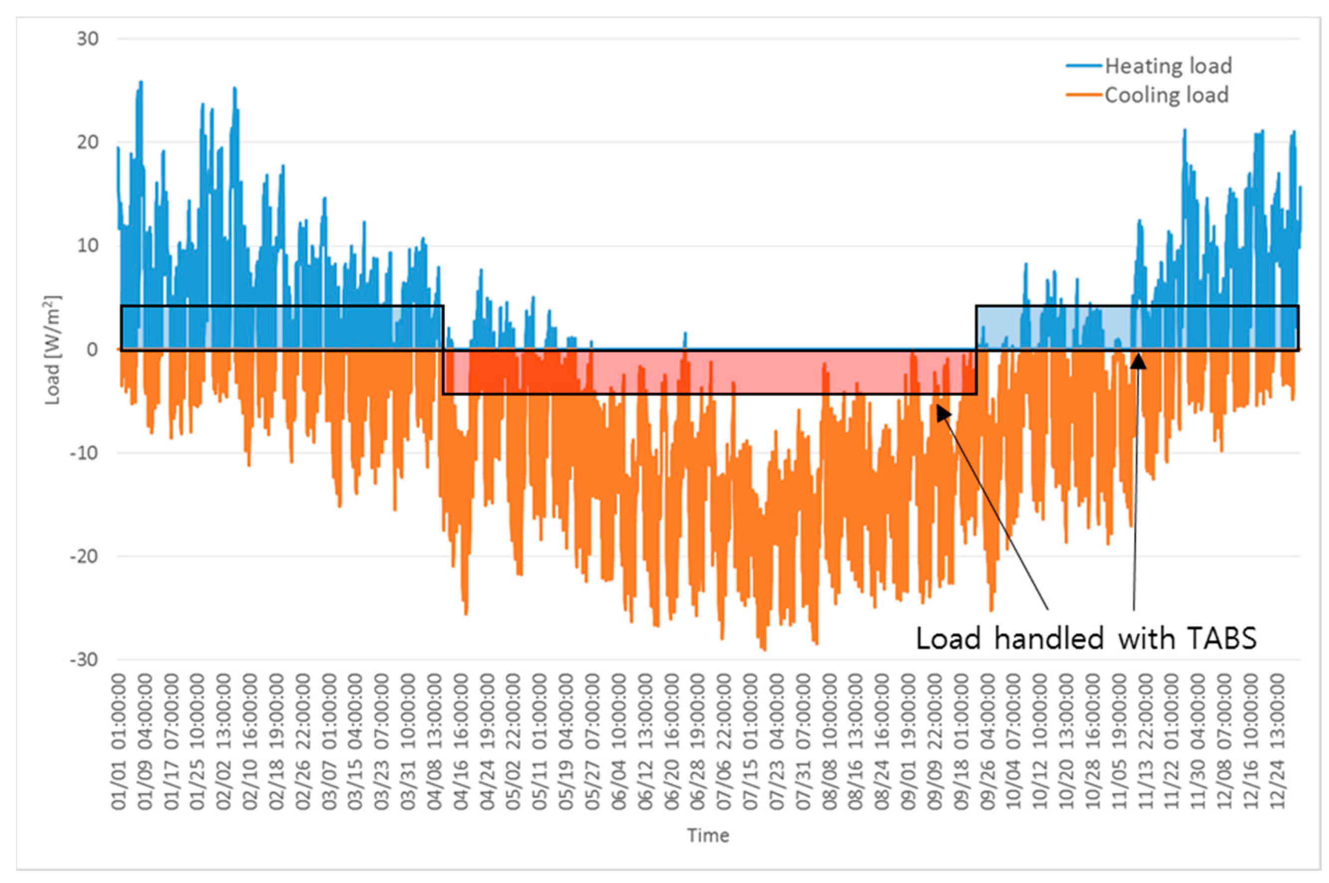
Self-regulation with the TABS can be implemented by maintaining the supply water temperature to be equivalent to the room setpoint temperature. When heating or cooling loads occur, the room temperature may decrease or increase, creating a temperature difference between the surface of the TABS and room and triggering a radiant and convective heat exchange. Figure 3 demonstrates the heating and cooling load of the building and handling of the expected load by TABS with self-regulation.
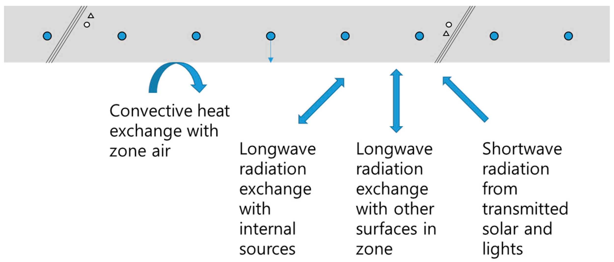
The concept of self-regulation is strongly related to the convective heat exchange between the room and system. However, longwave radiation heat exchange with other surfaces of the room and with internal sources, and shortwave radiation from transmitted solar and lights, may affect the results of the total heat exchange of the TABS as shown in Figure 4. Complex heat exchange with a variety of sources may result in deviation from the expected self-regulation. Therefore, we need to analyze the actual mechanism considering the constant supply water temperature.
2.2. Application of the TABS and Air System in Office Buildings
In order to discover whether the self-regulation of the TABS worked as expected to reduce the peak load, the convective and radiant heat exchange of the TABS were assessed. Since the radiant heat exchange can be explained using an unsteady-state, a dynamic simulation was performed to investigate the heat exchanges between the room and system.
In order to simulate a typical office building, the reference building proposed by the US Department of Energy was used to formulate the boundary conditions. Typical internal heat gain schedule and density from the document that National Renewable Energy Laboratory (NREL) of the US Department of Energy provided [2,21] were used. These are described in Table 1, and the building envelope is illustrated in Figure 5. Constant supply water temperature of TABS was 22 °C and used flow rate of 3600 kg/h. The air system used supply air temperature of 12 °C and 35 °C for cooling and heating, respectively.
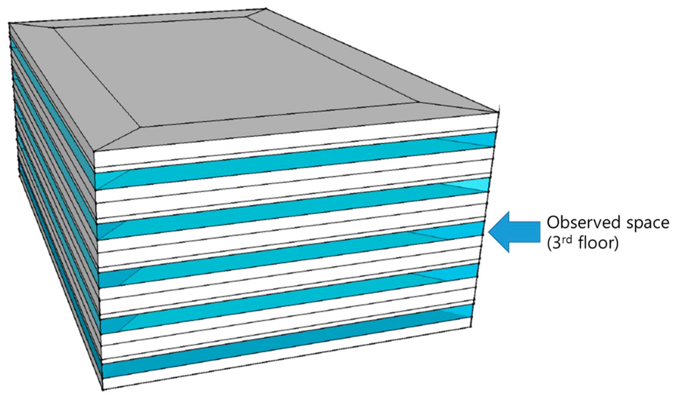
Since a lot of heat exchange occurs through the roof and ground and causes different load characteristics, the third floor was selected for evaluating the typical characteristics of the self-regulation mechanism of the TABS. Dynamic simulation was performed using the EnergyPlus software v8.6, and the TABS and air system were modeled for removing heating and cooling load. For modeling TABS, internal source was applied on each ceiling and used the system module, ZoneHVAC: Low Temperature Radiant: ConstantFlow, for supplying the water in a certain temperature. This system was connected to Plant Loop module to produce the heat. For air system, the air system module, ZoneHVAC: Ideal Loads Air System, was used. Peak heating and cooling days were chosen to examine the functioning of the TABS and air system in extreme conditions.
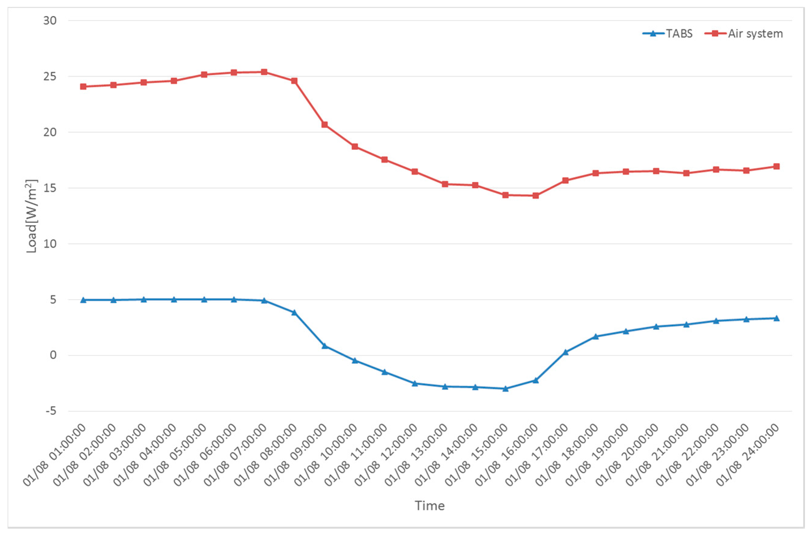
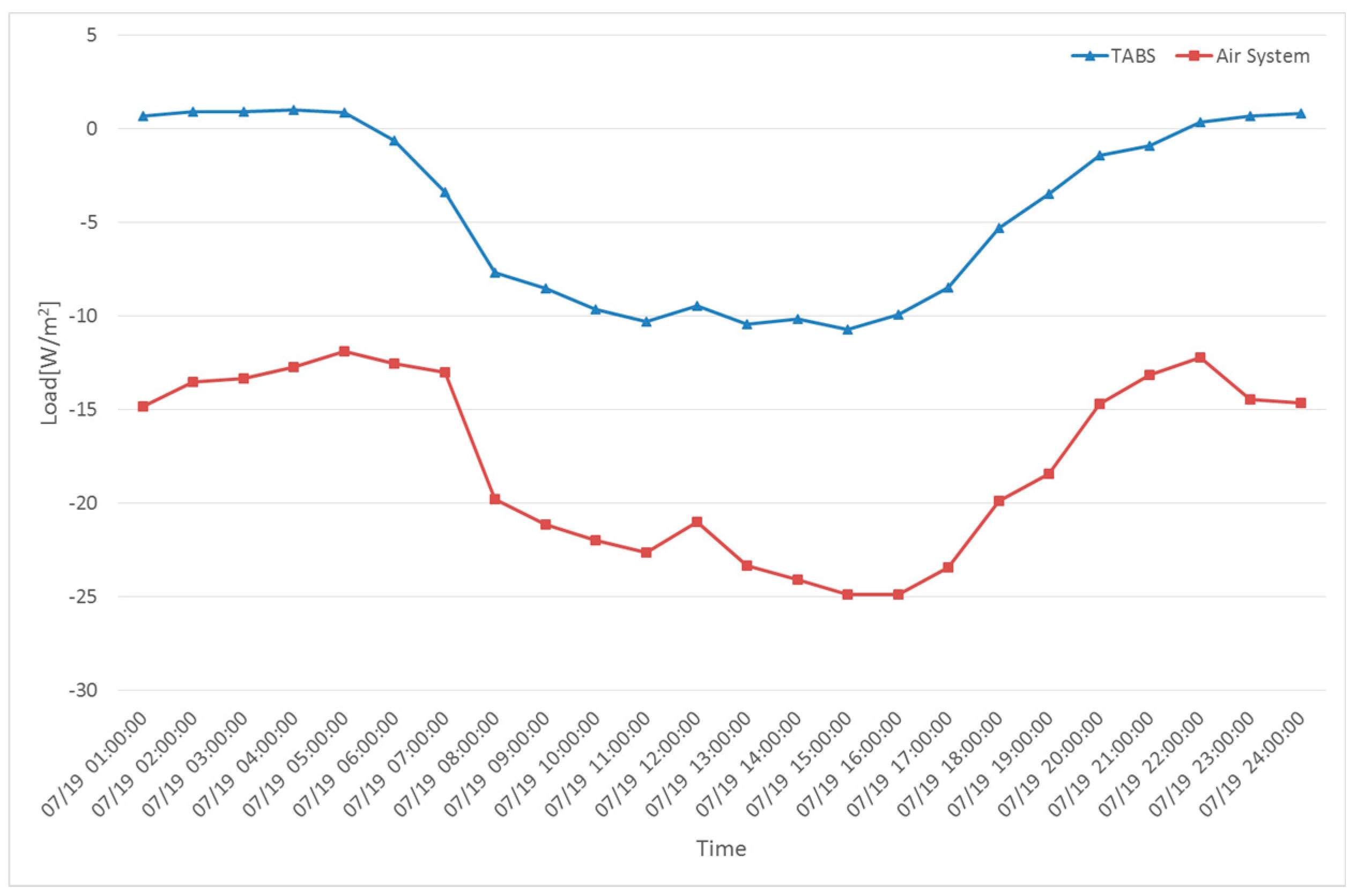
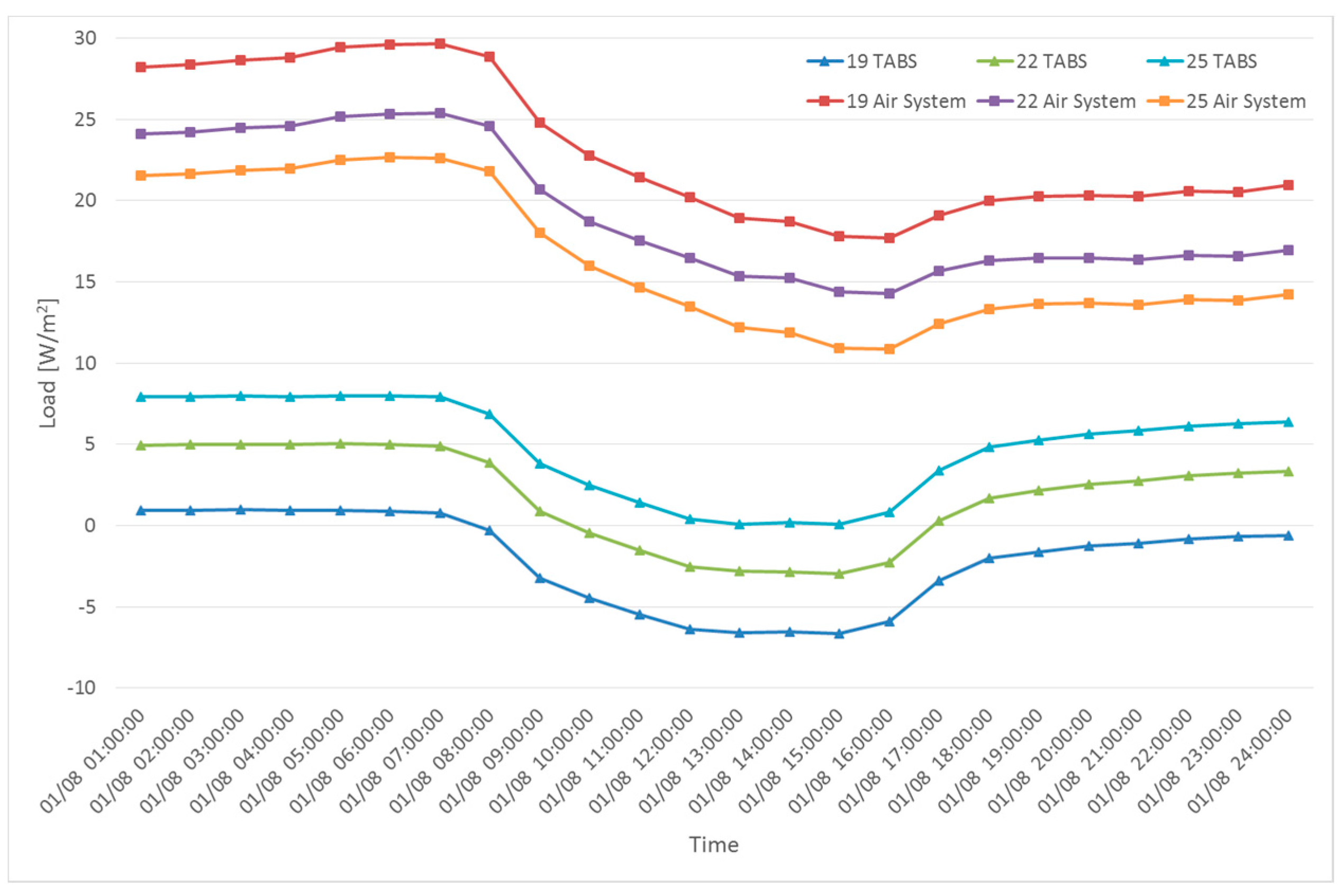
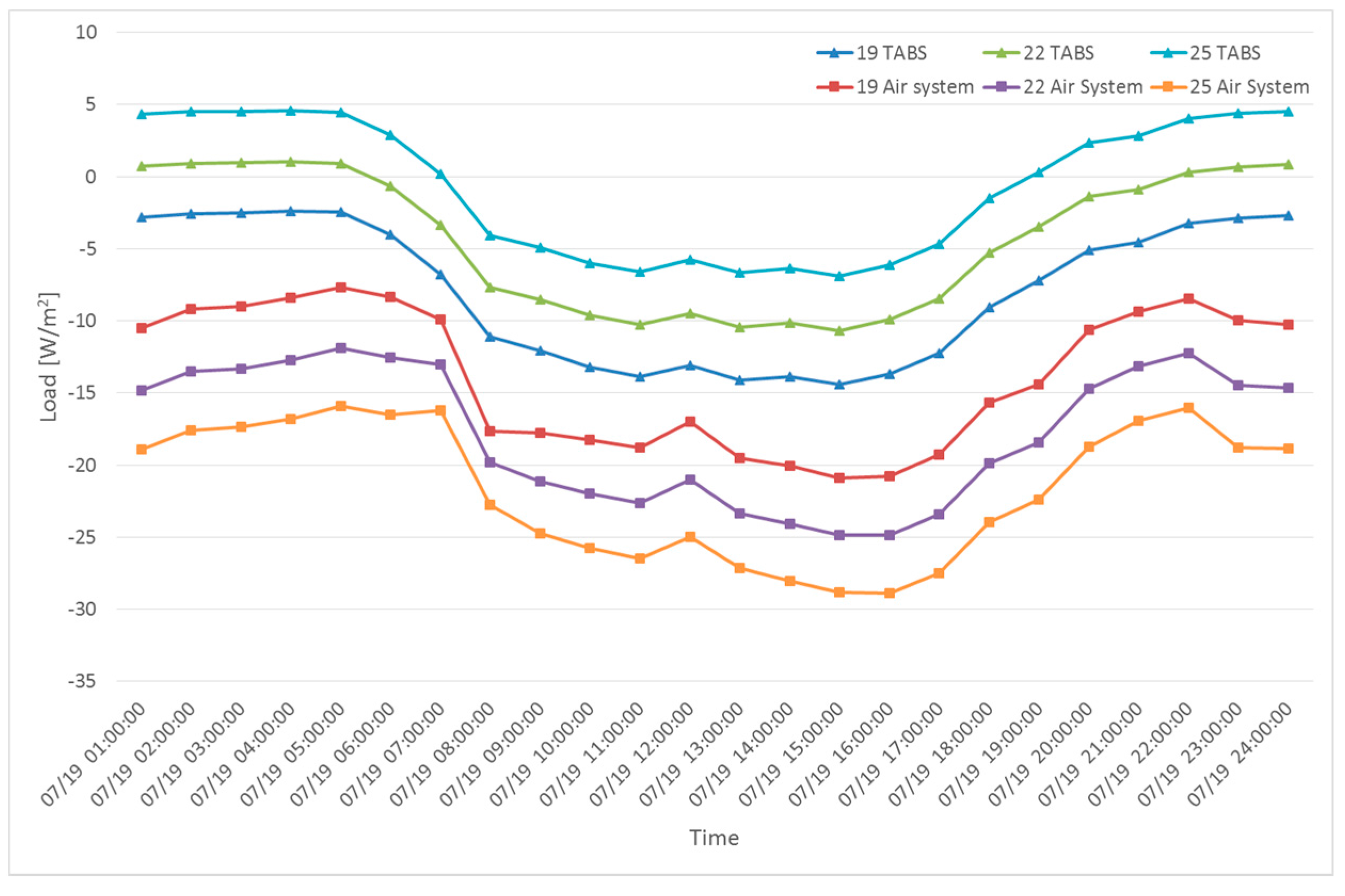
In Figure 6 and Figure 7, TABS load values are the heat exchange between TABS surface and the room and air system load values are the amount of heat transfer needed with air system to keep 22 °C of room temperature. In Figure 6, the TABS could remove a relatively large amount of heating load in the morning and night of a peak heating day. However, in the afternoon, the TABS absorbed coolness more than heat and became negative, which implies that the entire thermal mass of the TABS was not used and the self-regulation of the system was only partially executed. In Figure 7, a relatively significant amount of load was removed in the afternoon of a peak cooling day. However, in the morning and night, the TABS absorbed more heat than the coolness it provided. Since negative values appeared on peak heating and cooling days, only partial self-regulation was performed. Thus, higher and lower supply water temperatures need to be applied for heating and cooling, respectively, to increase the utilization of the TABS. The simulations were performed and results are demonstrated in Figure 8 and Figure 9 for removing the heating load and cooling load, accordingly. Since the design temperature difference between the supply and return temperature was 3 °C, supply water temperatures of 19 °C and 25 °C were used [22].
For increasing the utilization of the TABS by self-regulation of the entire thermal mass, different supply water temperatures were used. Supply water temperature of at least 19 °C can provide cooling at all times, and that of 25 °C can provide heating at all times. Hence, maximization of the self-regulation can be performed using targeting depending on whether heating or cooling load and supply is needed according to the purpose of the system.
2.3. Characteristics of Different Zone Loads
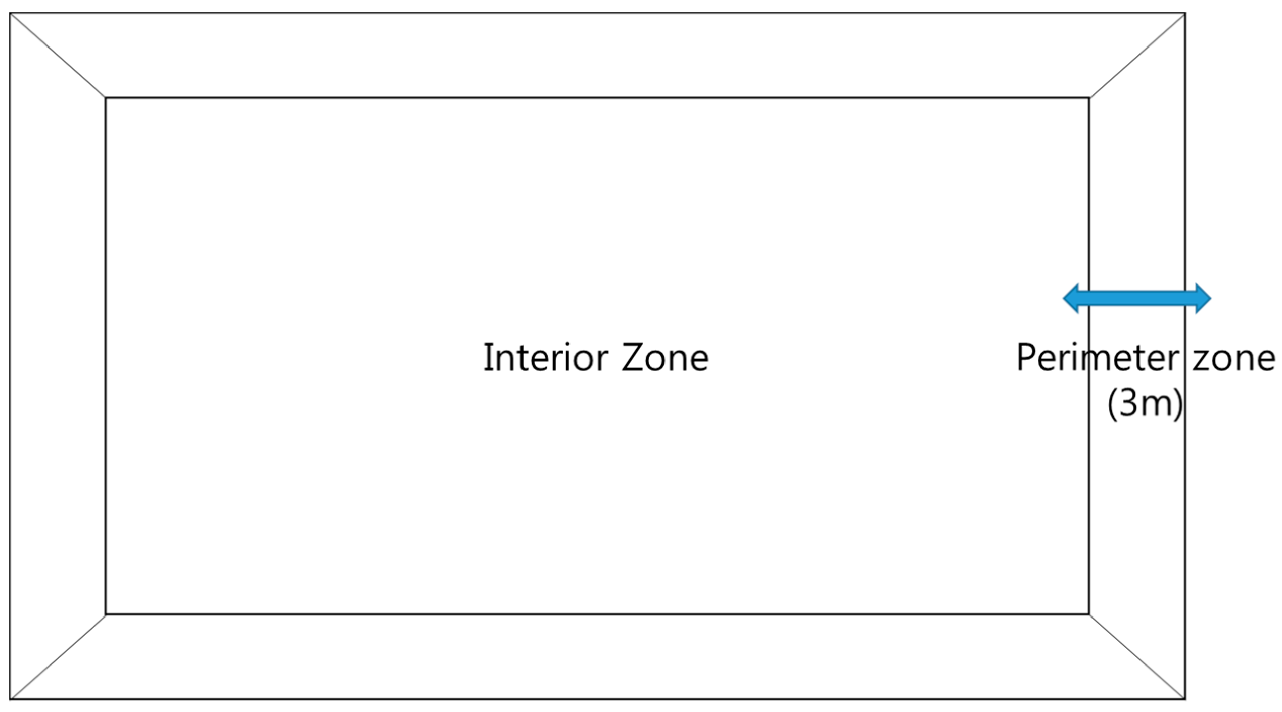
Since the supply water temperature must be fixed using a specific target for the self-regulation of the entire system, use of the TABS in a large office building area may be difficult. Different loads in different zones may occur and targeting a specific type of load may cause inefficiency in the system. The zoning of a typical office building is illustrated in Figure 10 by considering effects from outdoor conditions, such as outdoor air temperature and solar radiation.
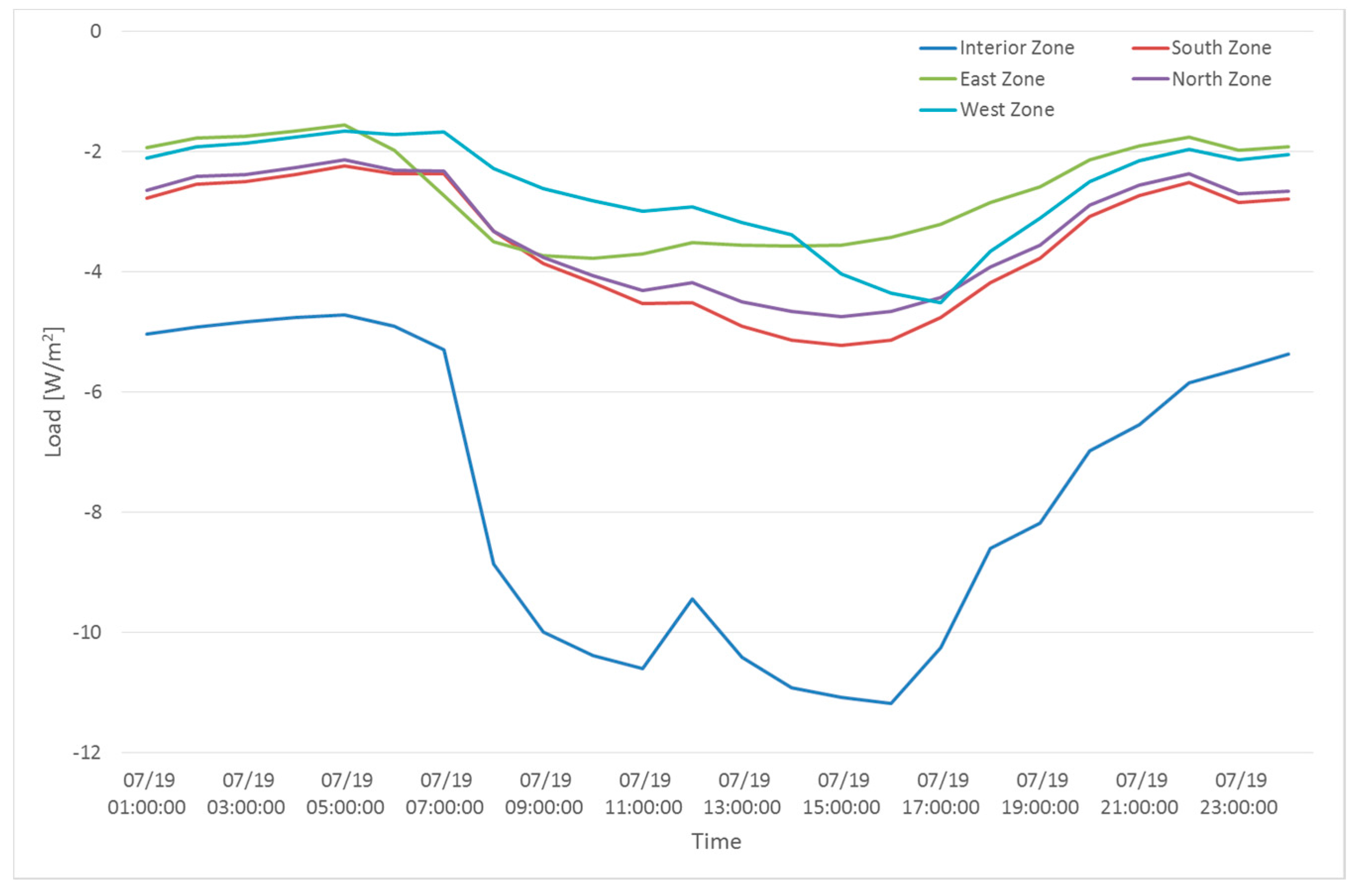
For a typical zoning of an office building, the cooling and heating loads in different zones are as shown in Figure 11 and Figure 12. For cooling load on a peak day, all the perimeter zone loads appear to be similar, because the office building has a large floor area and solar load per area is relatively low. The interior zone load is noticeably higher than the other zone loads because office buildings have high internal heat gains from people, lighting, and equipment. Moreover, the interior zone may not extract heat toward the outdoor environment.
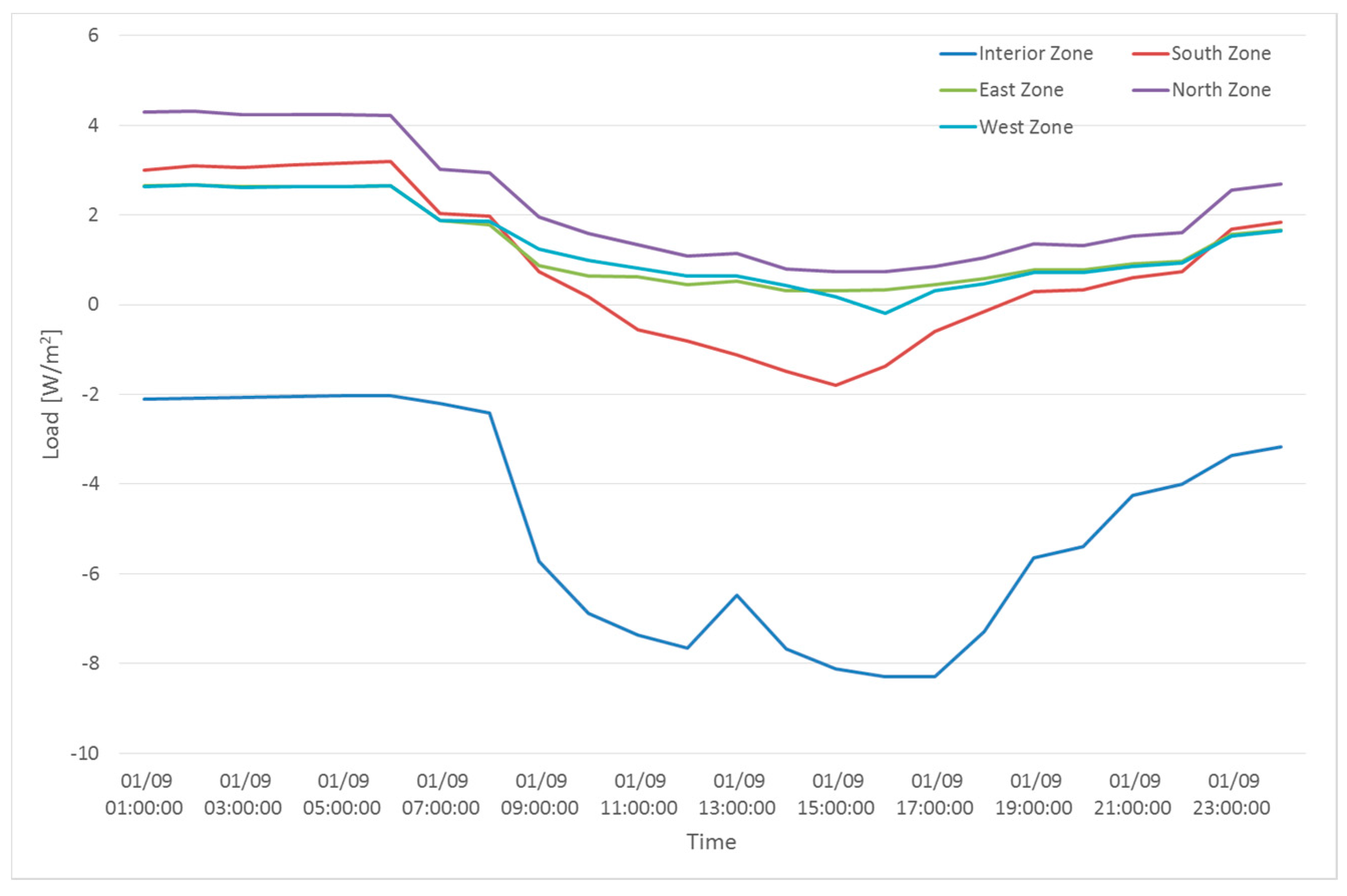
For heating load on a peak day, similar patterns of zone loads appeared in perimeter zones. However, the internal zone had cooling load instead of heating load and the south perimeter zone had cooling load during the day. When the TABS targets a specific type of load in a single zone, it will aim for heating load because the total load will be heating load on a peak day. As a result, the interior zone will be targeted for heating load instead of cooling load if the separate zone control of TABS is not performed. In this case, the utilization of TABS may decrease significantly. Therefore, appropriate control for each zone must be performed for maximizing the effectiveness of the TABS self-regulation.
3. Results and Discussion
3.1. Load Handled by the TABS and Air Systems in Different Zones
In order to perform self-regulation with the entire thermal mass of the TABS, the load target type and load variation with zone should be considered. First, the supply water temperature was varied and the zone load removal was observed to determine the control strategy.
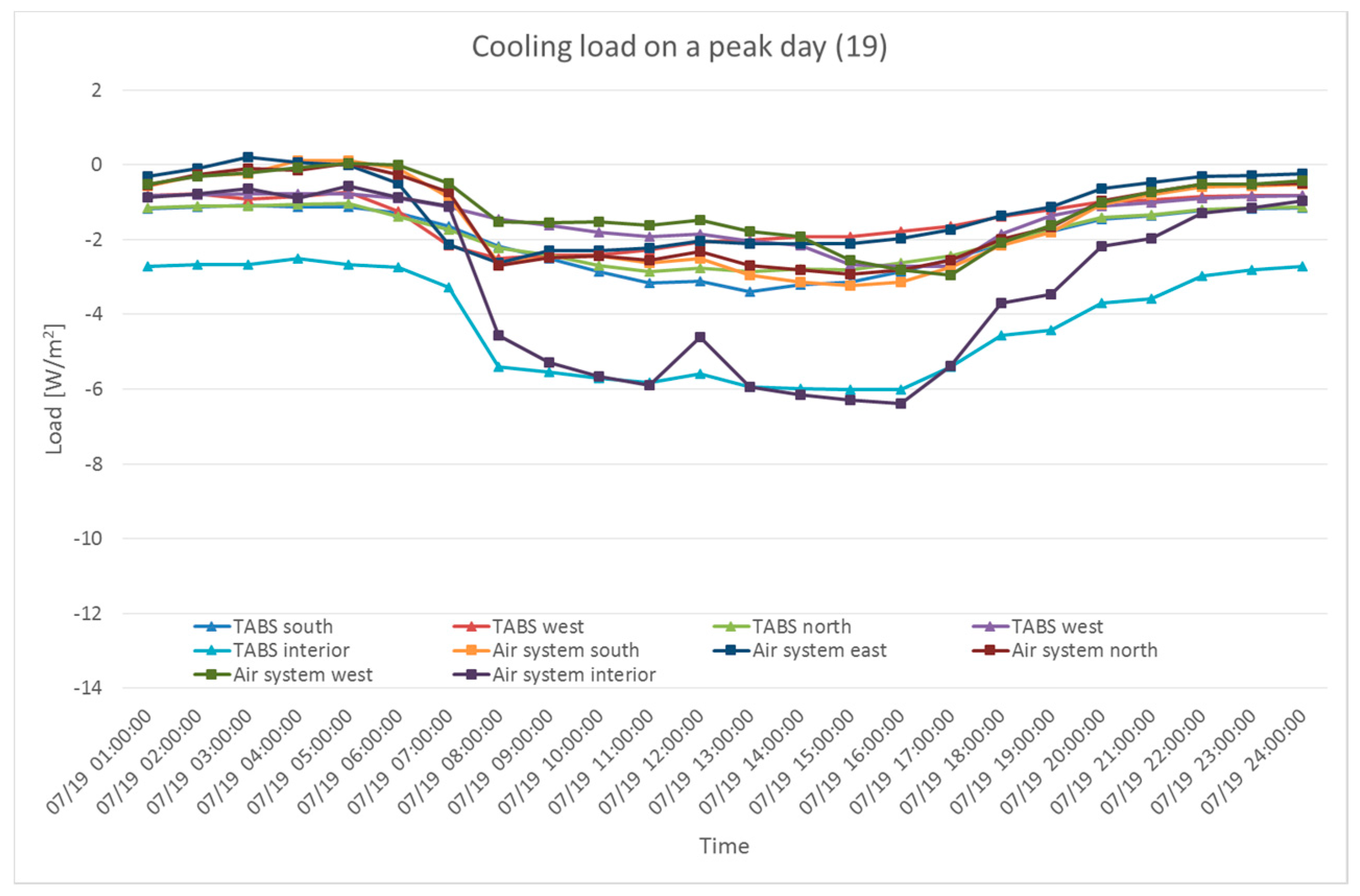
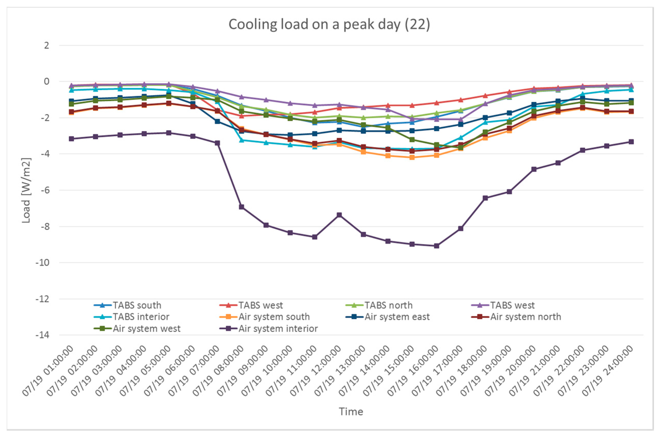
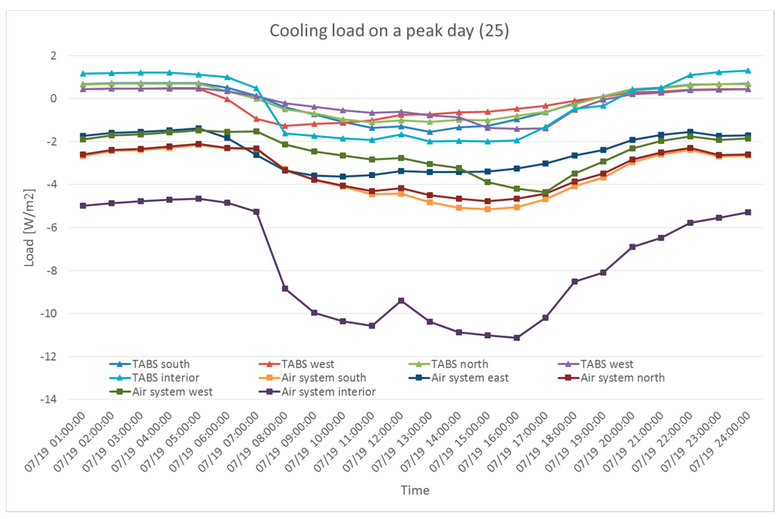
The different water temperatures supplied to the TABS on a cooling peak day are shown in Figure 13, Figure 14 and Figure 15. A supply water temperature of 19 °C handled as much load as the air system. During the night, the TABS handled most of the load in comparison with the air system in an interior zone. A supply water temperature of 22 °C handled minimum amount of load. The interior zone had a significant amount of cooling that was removed by the air system. A supply water temperature of 25 °C provided heating instead of cooling and increased the total cooling load during the night. During the day, cooling load was removed using the TABS because direct radiant heat exchange with internal heat source occurred.
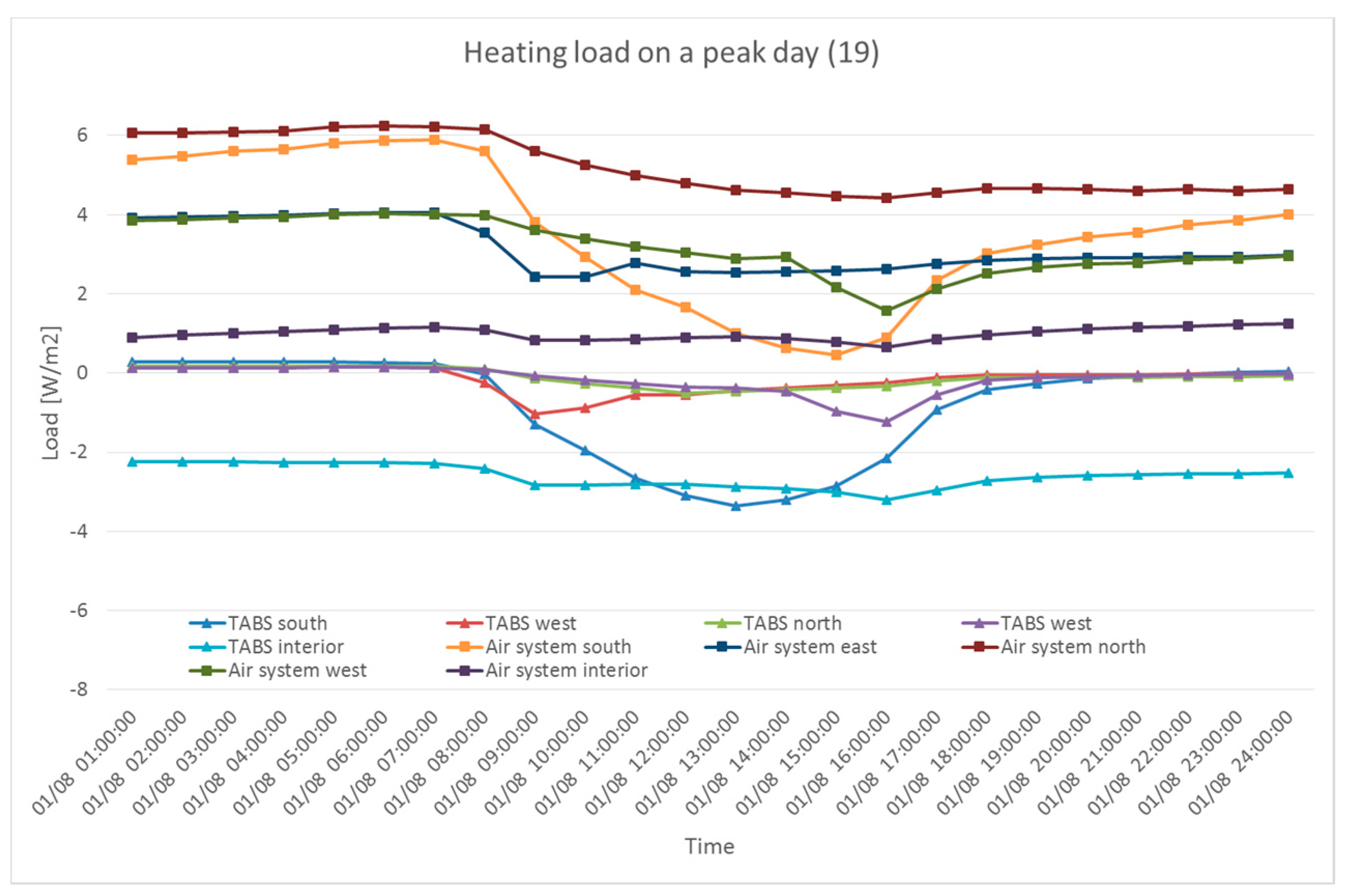
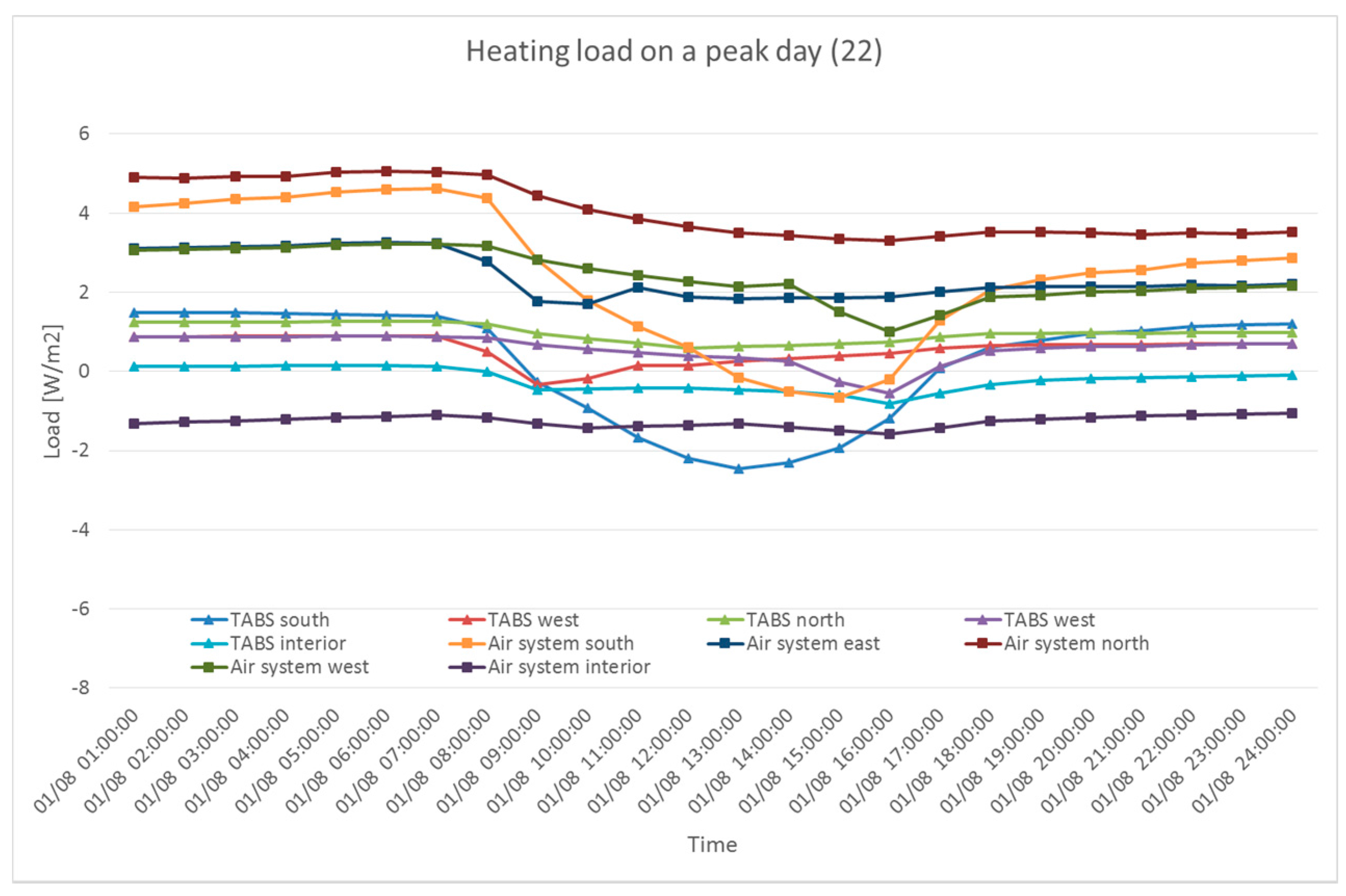
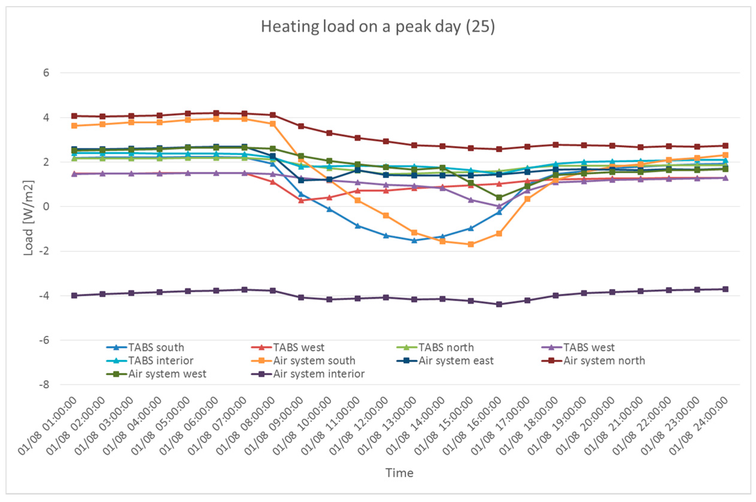
Different water temperatures were applied on a heating peak day as shown in Figure 16, Figure 17 and Figure 18. A supply water temperature of 19 °C demonstrated almost no heat exchange in the east, west and north zones. The south zone during the day and interior zone showed that the system removed the cooling load. However, the air system performed heating, which implies that the TABS in south zone and interior zone overcooled. A supply water temperature of 22 °C increased the amount of heating load handled using the TABS in the perimeter zones. A small amount of cooling load was removed in the interior zone, though most of the cooling load was removed by the air system. A supply water temperature of 25 °C on a heating peak day made the TABS in the perimeter zones remove as much heating load as the air system. The TABS in the south zone removed heating load during the morning and night and cooling load during the afternoon with air system. Nevertheless, the high supply water temperature in the interior zone also heated the interior space and increased the cooling loads.
By investigating the TABS load handled in each zone for different supply water temperatures, the cooling load may be appropriately handled using a single supply water temperature. However, during the heating period, many factors should be considered as the internal heat gain creates cooling load consistently. The amount of consistent cooling loads in the interior zone should be considered for deciding the supply water temperature of the TABS to avoid overcooling.
3.2. Control Strategy Considering the Different Zone Loads
The supply water temperature of the TABS should consider the characteristics of building load for each zone. The facts discovered about the interior and perimeter zones were applied to the different cases described in Table 2 to perform a comparative analysis. Case 1 used the conventional self-regulation control strategy to operate the TABS with a supply water temperature of 22 °C. Case 2 considered the consistent cooling load in interior zone and used TABS with supply water temperatures of 19 °C and 20 °C for cooling and heating, respectively. Case 3 considered not only the consistent cooling load in the interior zone, but also the seasonal changes in perimeter zones. In perimeter zones, supply water temperature of the TABS was adjusted to 19 °C during the summer season and 25 °C during the winter season. Supply water temperature of the TABS in interior zone was applied as in case 2.
In summer, the building requires the heating and cooling, simultaneously. Since typical radiant system supplies a particular temperature throughout the system, the plant system should be designed with proper zoning and efficient distribution. Moreover, plant design need to consider the relatively low supply water temperature for heating and high supply water temperature for cooling, because it increases the possibilities to use the renewable energy such as geothermal heat exchangers.
To evaluate the performance of the TABS, thermal comfort, peak load reduction and total energy consumption reduction values were compared. Thermal comfort was assessed using a common index from American Society of Heating, Refrigerating and Air-conditioning Engineers (ASHRAE), the Predicted Mean Vote (PMV) [23]. For peak load reduction, both heating and cooling loads were investigated and the total energy consumption was computed as a summation of the air system and TABS energy consumption.
The performance of TABS was compared in Table 3. As self-regulation was performed using the entire thermal mass of the TABS in cases 2 and 3, the utilization of TABS increased and indoor condition was more often within the allowable comfort range of −1 to 1. Since the PMV is strongly related to the mean radiant temperature, increase in the utilization of the TABS in cases 2 and 3 increased the mean radiant temperature for heating, decreased the mean radiant temperature for cooling, and improved the thermal comfort. Peak load reduction is critical for reducing the size of the system. As more considerations about heating and cooling loads in each zone were applied in the control strategy, heating and cooling load reduced. Since case 2 only dealt with cooling load, heating peak load did not reduce. However, removing the constant cooling load in the interior zone decreased the cooling load significantly. Case 3 reduced the peak load for both heating and cooling loads.
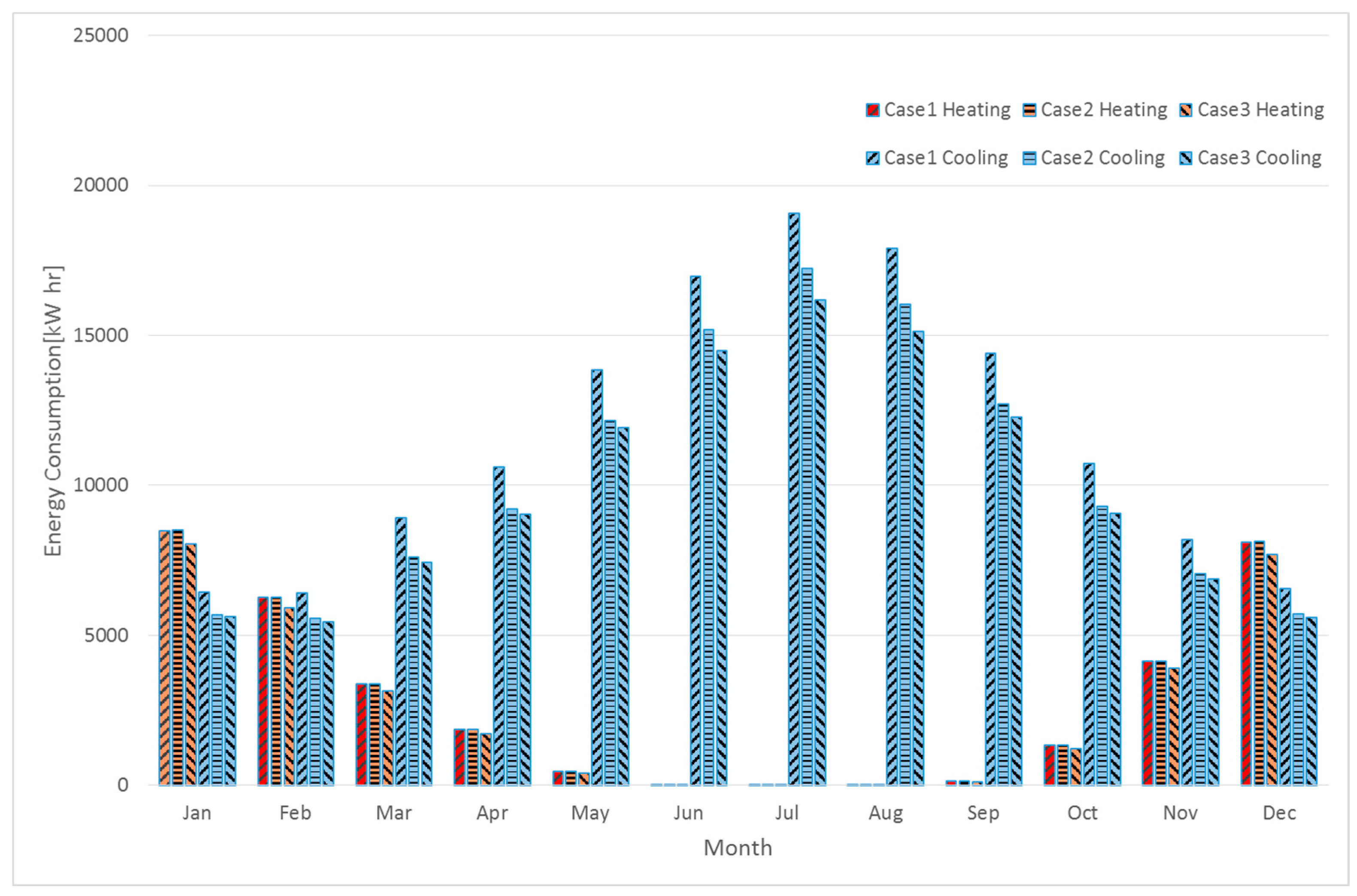
Moreover, the total energy consumption decreased as the use of the energy-efficient TABS increased. In Figure 19, monthly energy consumption for heating and cooling was demonstrated. Compared to the conventional control strategy with case 1, TABS in the interior zone decreased the energy consumption for the entire year in cooling. Since the area of TABS is smaller in parameter zones, case 3 reduced the energy consumption less than case 2. However, the energy consumption in case 3 was decreased for both heating and cooling due to the seasonal changes of the supply water temperature.
4. Conclusions
In this study, the conventional TABS control strategy of self-regulation was implemented using dynamic simulation, and the load handled by the TABS and air system were analyzed. The potential increase of the TABS utilization using control strategies that consider different loads for each zone was investigated.
In order to perform self-regulation with the entire thermal mass of the TABS and increase the utilization of the system, active control strategies that target the type of load and adjust the supply water temperature were found to be necessary.
Targeting the type of load might increase the utilization of the TABS. However, different loads may occur in different zones in an office building owing to the large amount of internal heat gain. A separate control strategy was proposed that resulted in improved thermal comfort, reduced peak load, and decrease of total energy consumption.
Considering the large building floor area and internal heat gain, TABS of the interior zone in office buildings should target the cooling load for the entire year. Contrast to the TABS in an interior zone, TABS in perimeter zones should apply the separate control strategy according to the external load of the building.
In future research, we expect to undertake a more detailed analysis of the system response with respect to the supply water temperature to increase the utilization of the TABS. In addition, studies on choosing an appropriate supply water temperature of TABS based on the building layout and properties will be performed.
Acknowledgments
This research was supported by Institute of Construction and Environmental Engineering at Seoul National University. The authors wish to express their gratitude for the support. This research was supported by Basic Science Research Program through the National Research Foundation of Korea (NRF) funded by the Ministry of Education (NRF-2015R1D1A1A09061467).
Author Contributions
Woong June Chung and Kwang Woo Kim had the original concept of the study, and all co-authors conceived and designed the methodology. Sang Hoon Park and Myoung Souk Yeo investigated the previous research and practical use of the system. Woong June Chung drafted the manuscript, and Kwang Woo Kim revised. All authors read and approved the final manuscript.
Conflicts of Interest
The authors declare no conflict of interest.
References
- Rhee, K.N.; Kim, K.W. A 50 year review of basic and applied research in radiant heating and cooling systems for the built environment. Build. Eviron. 2015, 91, 166–190. [Google Scholar] [CrossRef]
- National Renewable Energy Laboratory. Department of Energy Commercial Reference Building Models of the National Building Stock; Technical Report; National Renewable Energy Laboratory: Golden, CO, USA, 2011.
- ISO. Standard 11855-2:2012(E). Building Environment Design—Design, Dimen-Sioning, Installation and Control of Embedded Radiant Heating and Cooling Systems—Part 4: Dimensioning and Calculation of the Dynamic Heating and Cooling Capacity of Thermo Active Building Systems (TABS); ISO: Geneva, Switzerland, 2012. [Google Scholar]
- Olesen, B.W. Operation and Control of Thermally Activated Slab Heating and Cooling Systems. In Proceedings of the CIB World Congress 2004, Toronto, ON, Canada, 2–7 May 2004. [Google Scholar]
- Olesen, B.W.; DeCarli, M.; Scarpa, M.; Koschenz, M. Dynamic evaluation of the cooling capacity of thermo active building systems. ASHRAE Trans. 2006, 112, 350–357. [Google Scholar]
- Olesen, B.W. Using building mass to heat and cool. ASHRAE J. 2012, 54, 12–17. [Google Scholar]
- Park, S.H. Evaluation of the thermal performance of a Thermally Activated Building System (TABS) according to the thermal load in a residential buildings. Energy Build. 2014, 73, 69–82. [Google Scholar] [CrossRef]
- Rijksen, D.O. Reducing peak requirements for cooling by using thermally activated building system. Energy Build. 2010, 42, 298–306. [Google Scholar] [CrossRef]
- Babiak, J.; Olesen, B.W.; Petras, D. Low Temperature Heating and High Temperature Cooling; Federation of European Heating and Air-Conditioning Associations (REHVA): Brussels, Belgium, 2007. [Google Scholar]
- Todtli, J.; Gwerder, M.; Lehmann, B.; Renggli, F.; Dorer, V. Integrated design of thermally activated buildings systems and of their control. In Proceedings of the 9th REHVA World Congress for Building Technologies, Helsinki, Finland, 10–14 June 2007. [Google Scholar]
- Olesen, B.W.; Sommer, K.; Duchting, B. Control of Slab heating and Cooling Systems Studied by Dynamic Computer Simulations. ASHRAE Trans. 2002, 108, 698–707. [Google Scholar]
- Lehmann, B.; Dorer, V.; Gwerder, M.; Renggli, F.; Todtli, J. Thermally activated building systems (TABS): Energy efficiency as a function of control strategy, hydronic circuit topology and (cold) generation system. Appl. Energy 2011, 88, 180–191. [Google Scholar] [CrossRef]
- Gwerder, M.; Lehmann, B.; Todtli, J.; Dorer, V.; Fenggli, F. Control of thermally activated building systems (TABS). Appl. Energy 2008, 84, 565–581. [Google Scholar] [CrossRef]
- Gwerder, M.; Todtli, J.; Lehmann, B.; Dorer, V.; Guntensperger, W.; Renggli, F. Control of thermally activated building systems (TABS) in intermittent operation with pulse width modulation. Appl. Energy 2009, 86, 1606–1616. [Google Scholar] [CrossRef]
- Lehmann, B.; Dorer, V.; Koschenz, M. Application range of thermally activated building systems tabs. Energy Build. 2007, 39, 593–598. [Google Scholar] [CrossRef]
- Lim, J.H.; Song, J.H.; Song, S.Y. Development of operational guidelines for thermally activated building system according to heating and cooling load characteristics. Appl. Energy 2014, 126, 123–135. [Google Scholar] [CrossRef]
- Schmelas, M.; Feldmann, T.; Bollin, E. Adapative predictive control of thermo-active building systems (TABS) based on a multiple regression algorithm. Energy Build. 2015, 103, 14–28. [Google Scholar] [CrossRef]
- Schmelas, M.; Feldmann, T.; Wellnitz, P.; Bollin, E. Adapative predictive control of thermo-active building systems (TABS) based on a multiple regression algorithm: First practical test. Energy Build. 2016, 129, 367–377. [Google Scholar] [CrossRef]
- Sourbron, M.; Helsen, L. Sensitivity analysis of feedback control for concrete core activation and impact on installed thermal production power. J. Build. Perform. Simul. 2014, 7, 309–325. [Google Scholar] [CrossRef]
- Arteconi, A.; Costola, D.; Hoes, P.; Hensen, J.L.M. Analysis of control strategies for the thermally activated building systems under demand side management mechanisms. Energy Build. 2014, 80, 384–393. [Google Scholar] [CrossRef]
- ASHRAE Standard 90.1. Energy Standard for Buildings Except Low-Rise Residential Buildings; American Society of Heating, Refrigerating and Air-Conditioning Engineers, Inc.: Atlanta, GA, USA, 1989. [Google Scholar]
- Chung, W.J.; Park, S.H.; Yeo, M.S.; Kim, K.W. Feasibility of a thermally activated building system in residential buildings. In Proceedings of the ISES Solar World Congress 2011, Kassel, Germany, 28 August–2 September 2011. [Google Scholar]
- ANSI/ASHRAE Standard 55. Thermal Environmental Conditions for Human Occupancy; American Society of Heating, Refrigerating and Air-Conditioning Engineers, Inc.: Atlanta, GA, USA, 2010. [Google Scholar]
Figure 1.
Section view of the thermally activated building system (TABS).

Figure 2.
Design load handled with the different systems.

Figure 3.
Office building load and expected load handled using the TABS.

Figure 4.
Heat exchange between room and the system.

Figure 5.
Reference building for analyzing the TABS.

Figure 6.
Heating load handled using the TABS (22 °C) and air system on a peak day.

Figure 7.
Cooling load handled using the TABS (22 °C) and air system on a peak day.

Figure 8.
Heating load handled using the TABS and air system on a peak day.

Figure 9.
Cooling load handled using the TABS and air system on a peak day.

Figure 10.
Typical zone in an office building.

Figure 11.
Cooling load for different zones on a peak day.

Figure 12.
Heating load for different zones on a peak day.

Figure 13.
Cooling load in different zones on a peak day (supply 19 °C).

Figure 14.
Cooling load in different zones on a peak day (supply 22 °C).

Figure 15.
Cooling load in different zones on a peak day (supply 25 °C).

Figure 16.
Heating load in different zones on a peak day (supply 19 °C).

Figure 17.
Heating load in different zones on a peak day (supply 22 °C).

Figure 18.
Heating load in different zones on a peak day (supply 25 °C).

Figure 19.
Monthly energy consumption.


Table 1.
Boundary conditions for simulation.
| Conditions | Content |
|---|---|
| Building Orientation | South |
| District | Chicago, IL, USA |
| Area | 1650 m2 (50 m × 33 m) |
| Window Properties | Window to Wall Ratio 30%, Solar Heat Gain Coefficient of 0.39, No Blinds |
| Internal Heat Gain | People: 0.054 Person/m2, Lighting: 10.76 W/m2, Equipment: 10.76 W/m2 |
| Setpoint Temperature | 22 °C |
| Supply Water Temperature of TABS | 22 °C |
| TABS Operation | 24 h of Operation |
| Air System Operation | 24 h of Operation |
| TABS Placement | Ceiling (Slab) |
| Plant for Cooling | Chiller |
| Plant for Heating | Boiler |
Table 2.
Cases of different control strategies of the TABS considering different zone loads.
| Cases | Control of TABS | Supply Water Temperature of Interior Zone for Cooling (°C) | Supply Water Temperature of Interior Zone for Heating (°C) | Supply Water Temperature of Perimeter Zones for Cooling (°C) | Supply Water Temperature of Perimeter Zones for Heating (°C) |
|---|---|---|---|---|---|
| Case 1 | Conventional control strategy with self-regulation | 22 | 22 | 22 | 22 |
| Case 2 | Constant removal of cooling load in interior zone | 19 | 20 | 22 | 22 |
| Case 3 | Adjustment of supply water temperatures in perimeter zones for each season and constant removal of cooling load in interior zone | 19 | 20 | 19 | 25 |
Table 3.
Performance comparison of the TABS for each case.
| Predicted Mean Vote | Case 1 | Case 2 | Case 3 | |
|---|---|---|---|---|
| Conventional Self-Regulation Control | Control Interior Zone | Control Perimeter Zone and Interior Zone | ||
| (°C) | (%) | (%) | (%) | |
| Thermal Comfort | <−3 | - | - | - |
| −3 to −2 | - | - | - | |
| −2 to −1 | 4 | 4 | 3 | |
| −1 to 1 | 90 | 94 | 95 | |
| 1 to 2 | 6 | 2 | 2 | |
| 2 to 3 | - | - | - | |
| >3 | - | - | - | |
| Peak load reduction | Heating load | - | - | 10 |
| Cooling load | - | 30 | 36 | |
| Total energy consumption reduction | - | 9 | 13 | |
© 2017 by the authors. Licensee MDPI, Basel, Switzerland. This article is an open access article distributed under the terms and conditions of the Creative Commons Attribution (CC BY) license (http://creativecommons.org/licenses/by/4.0/).
Share and Cite
MDPI and ACS Style
Chung, W.J.; Park, S.H.; Yeo, M.S.; Kim, K.W. Control of Thermally Activated Building System Considering Zone Load Characteristics. Sustainability 2017, 9, 586. https://doi.org/10.3390/su9040586
AMA Style
Chung WJ, Park SH, Yeo MS, Kim KW. Control of Thermally Activated Building System Considering Zone Load Characteristics. Sustainability. 2017; 9(4):586. https://doi.org/10.3390/su9040586
Chicago/Turabian StyleChung, Woong June, Sang Hoon Park, Myoung Souk Yeo, and Kwang Woo Kim. 2017. "Control of Thermally Activated Building System Considering Zone Load Characteristics" Sustainability 9, no. 4: 586. https://doi.org/10.3390/su9040586
Note that from the first issue of 2016, this journal uses article numbers instead of page numbers. See further details here.