
Early-Stage Design Considerations for the Energy-Efficiency of High-Rise Office Buildings


Department of Architectural Engineering + Technology, Faculty of Architecture and the Built Environment, Delft University of Technology, P.O. Box 5043, 2600 GA Delft, The Netherlands
*
Author to whom correspondence should be addressed.
Sustainability 2017, 9(4), 623; https://doi.org/10.3390/su9040623
Submission received: 10 March 2017
/
Revised: 7 April 2017
/
Accepted: 12 April 2017
/
Published: 17 April 2017
(This article belongs to the Special Issue Sustainable Architecture and Design)
Abstract
:Decisions made at early stages of the design are of the utmost importance for the energy-efficiency of buildings. Wrong decisions and design failures related to a building’s general layout, shape, façade transparency or orientation can increase the operational energy tremendously. These failures can be avoided in advance through simple changes in the design. Using extensive parametric energy simulations by DesignBuilder, this paper investigates the impact of geometric factors for the energy-efficiency of high-rise office buildings in three climates contexts: Amsterdam (Temperate), Sydney (Sub-tropical) and Singapore (Tropical). The investigation is carried out on 12 plan shapes, 7 plan depths, 4 building orientations and discrete values for window-to-wall ratio. Among selected options, each sub-section determines the most efficient solution for different design measures and climates. The optimal design solution is the one that minimises, on an annual basis, the sum of the energy use for heating, cooling, electric lighting and fans. The results indicate that the general building design is an important issue to consider for high-rise buildings: they can influence the energy use up to 32%. For most of the geometric factors, the greatest difference between the optimal and the worst solution occurs in the sub-tropical climate, while the tropical climate is the one that shows the smallest difference. In case of the plan depth, special attention should be paid in the case of a temperate climate, as the total energy use can increase more than in other climates. Regarding energy performance, the following building geometry factors have the highest to lowest influence: building orientation, plan shape, plan depth, and window-to-wall ratio.
1. Introduction
In the early phases of the design process, the design of a building may be influenced by several factors such as site limitations, client demands (e.g., maximum space efficiency for return of investment), functional and aesthetic quality, costs, building codes, urban regulations, and last but not least the desire of the designer/client to reduce the environmental impact resulting from energy consumption and CO2 emissions.
During the early design phases, the decisions made by the designer can have a significant influence on the building’s energy performance [1]. The general building layout is of great importance for minimising the energy loads and for enabling passive design strategies. There is a growing awareness to use building performance simulation tools during the design process [2]. According to a survey conducted by Athienitis and Attia [3], about 60% of energy models are created for the early stage design. Building shape and orientation together with the general design of the envelope are the main areas of focus for energy modelling during the early design phase.
2. Overview of Previous Studies
The impact of building shape on energy performance has been investigated widely since the development of building performance simulation tools. Several studies have shown that a correlation exists between a building’s compactness and its energy consumption [4,5,6,7,8]. Compactness of a building is defined as the ratio of the area of the external envelope (A) to the volume (V). Findings showed that compact shapes can result in lower energy consumption, especially in hot and cold climates [9].
A number of studies researched the application of the relative compactness (RC) coefficient for creating predictive equations [4,5,6]. Relative compactness shows the deviation of the compactness of a building from the most compact shape. An example is the study done by Pessenlehner and Mahdavi [4]. They examined the reliability of the relative compactness indicator for the evaluation and prediction of annual heating loads and the total number of overheating hours by running several thermal simulations on hypothetical buildings with residential use in Vienna. A total number of 720 combinations were generated from 12 shapes, 4 orientations, 3 glazing ratios (10%, 25% and 40%) and 5 alternatives for the distribution of glazing across the external walls. 18 modular cells (3.5 × 3.5 × 3.5 m) were integrated in different ways to create various building forms at a given volume. Using the cube as a reference shape, the relative compactness of the different hypothetical buildings was in a range between 0.98 and 0.62. They found that the respective correlation between heating load and relative compactness (RC) is reasonably high (R2 = 0.88). Furthermore, they explored the accuracy of the proposed regression equation to predict the heating load of five distinct shapes with the same RC value (0.86). The simulated results deviated from the predicted values in a range between −15% and +10%, which indicates the reliability of RC for assessing heating loads in buildings. However, the predictions showed a large deviation (−80% to +130%) in case of overheating predictions.
Depecker, Menezo, Virgone and Lepers [5] investigated the relationship between shape (shape coefficient) and the energy consumption for heating of buildings in a cold, and a mild climate at the northern hemisphere. For the evaluation of the building’s thermal behaviour a calculation method based on weighting factors was applied. In their study, 16 cubic elements (5.4 × 5.4 × 5.4 m) were aggregated under two main categories of single- and multi-blocks to create 14 building morphologies. For all buildings, the largest façade was facing along north-south and the proportional percentage of glazed area to external walls was the same in all cases (south: 58%, east and west: 17% and north: 8%). The correlation between the energy consumption for heating and the shape coefficient was investigated for the studied shapes. The results showed that a good linear correlation (R2 = 0.91) existed in the cold climate and that the shape coefficient turned out to be a good indicator to assess the energy use for heating. In contrast, a weak correlation was found in case of the mild climate. Due to long periods of sunshine, the incident solar energy flux through glazing is high; hence, heat losses from the building skin have a smaller impact on the energy balance. As a result, the correlation between the shape coefficient and energy consumption was weak. Furthermore, the results showed that building shapes with higher total area of glazing (mostly non-monolithic forms) had less deviation from the regression line.
Ourghi, Al-Anzi and Krarti [6] developed a calculation method that can predict the annual total energy use of different building forms using the energy results obtained from a reference shape with a square floor plan. For all building configurations, the total building volume of conditioned space remained constant. Using the DOE-2 simulation tool, they came up with a correlation equation that can predict accurately the relative annual total building energy use as a function of three parameters, including relative compactness, glazing area and the solar heat gain coefficient (SHGC) of the glazing. Furthermore, they found the impact of the insulation level of the building envelope to be insignificant. However, this equation is only applicable for cities with cooling-dominated climates and the result is only valid for buildings that have the same floor area and the volume of the reference building.
AlAnzi, Seo and Krarti [7] conducted an investigation on several plan shapes with different geometric dimensions, window-to-wall ratios (WWRs) and orientations for the hot and arid climate of Kuwait. They found that the annual total building energy use for all building shapes decreases as the relative compactness increases. A change of the glazing area from 50% to 0% (no glazing) resulted in the same trend; an increase of RC leads to a reduction of energy use. Additionally, they found that orientation has an impact on building energy use, its effect however being almost independent of the building’s shape, especially for lower values of the window-to-wall ratio. It should be noted that their approach for the selection of building shapes can be subject of debate since a large number of the analysed plan configurations were not appropriate for the architectural design of office buildings (e.g., 2 m plan depth or no glazing for all directions).
Few studies took real case buildings to identify the impact of building shapes on energy consumption. A comparative case-study was conducted by Choi, Cho and Kim [8] on tall residential complexes in Korea in order to find the relation between building shape and energy consumption. They compared two plan forms: a Y-shaped and an I-shaped floor plan. For the purpose of comparison, the total electricity and gas consumption of households and common areas were calculated as a fraction of the total floor area in each case. They found that a linear I-shaped floor plan performed better in terms of total electricity consumption but consumed 10% more gas than the Y-shaped building. Furthermore, they mentioned that the architectural arrangement of units can influence the energy consumption. The Y-shaped building has three units around a central core while the two units of the I-shape building have just one shared wall and therefore a larger ratio of external wall surface area to their volume. In this study the insulation performance and the geographical location of both buildings were selected in a way to be almost identical. However, the influence of other design parameters such as WWR or building orientation was not discussed adequately where it may impact energy consumption.
Multiple studies have explored the optimal building shape by using numerical calculations [10] or evolutionary algorithms such as the genetic algorithm (GA) [10,11,12,13]. There are some arguments for and against the application of multi-objective optimisation methods in comparison with conventional trial-and-error methods. New methods of optimisation by using GA allow the user to explore site-specific complex building geometries without being restricted to a simple form [14]. On the contrary, the simulations require a long time to run, the utilised method is complex and requires specialised expertise and is therefore not easy to be used by designers [15]. Due to these constraints, designers are still relying on conventional trial-and-error methods for decision making at early-stage design despite the improvements that have been made in integrating optimisation methods into simulation tools.
From the overview of previous studies, it can be highlighted that compactness is not the only building layout measure influencing energy consumption, although it might be the most influential parameter in climates that have a high demand for heating or cooling. Compactness does not reflect the three-dimensional massing of a building’s shape (e.g., self-shading), the transparency of the building enclosure (e.g., amount and distribution of windows), and the orientation of a building; hence, corresponding gains and losses are not being accounted for, even if they might have impact on energy consumption. In addition, most studies are on low-rises or a combination of building heights (dependent on the shape to be compared). As a result, this study aims to investigate the impact of building geometry of high-rise office buildings (40-storey) on the total energy use (and different energy end-uses), by investigating different combinations of plan shapes, plan aspect ratios, windows (percentage and distribution) and building orientations.
3. Methodology
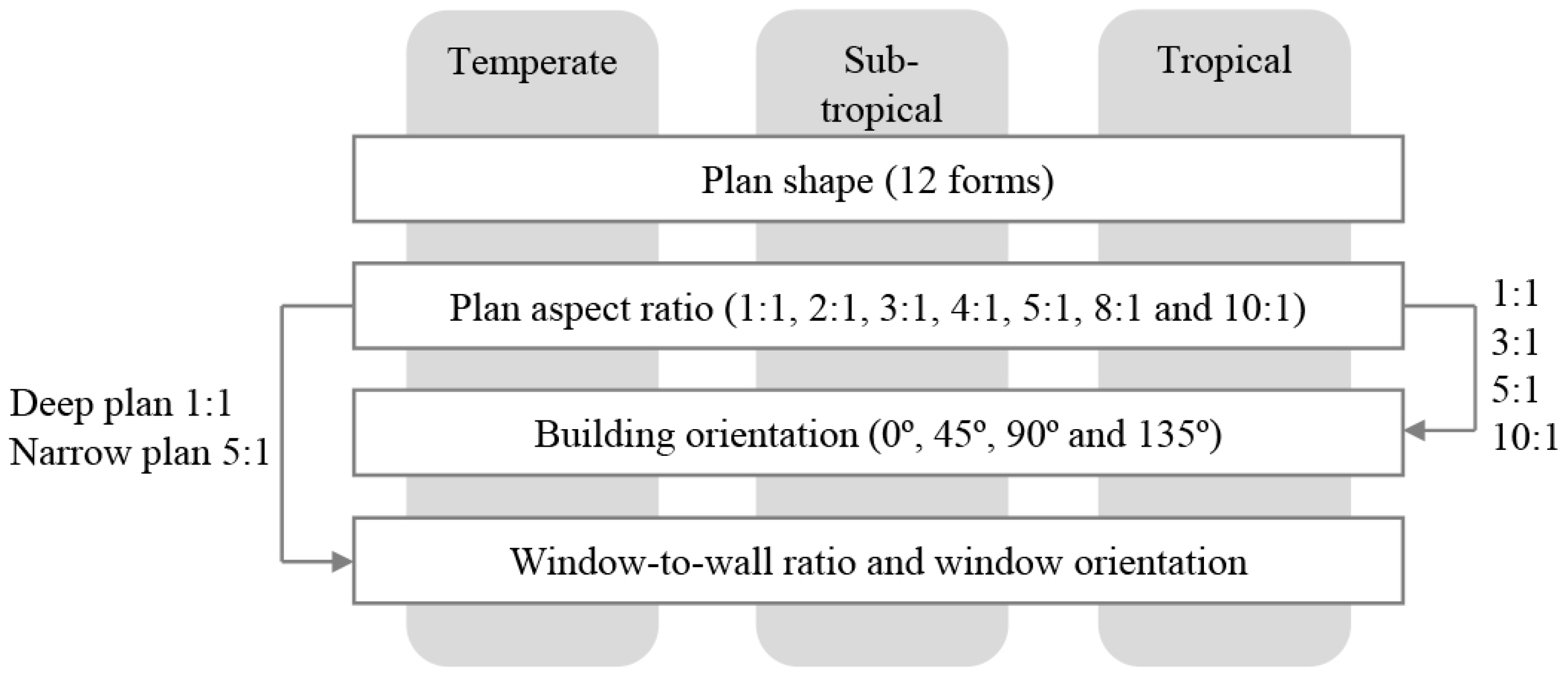
The overall methodological scheme of this research is summarised in Figure 1. The main objective of this study is to investigate the impact of geometry factors on energy-efficiency of high-rise office buildings in three climates. The geometry factors that have been investigated in this research are plan shape, plan depth, building orientation, window-to-wall ratio and window orientation. While comparing the climate and population density maps, it shows that the most densely populated cities around the world are mainly located in temperate, sub-tropical and tropical climates. These are the places where the majority of tall buildings are being constructed. As a result, this study aimed to answer the following questions in the context of the three climates:
What is the most energy-efficient building shape for high-rise office buildings?
Which aspect ratio of the floor plan performs best when considering the total energy use for heating, cooling, lighting and fans?
To what extent can floor plan orientation influence the energy performance?
What is the optimal range of glazed area for the different facades of high-rise office buildings?
3.1. Building Model
To investigate the effect of geometry factors, DesignBuilder version 4.7 (DesignBuilder Software Ltd., London, UK) was used. DesignBuilder is a powerful interface that incorporates the EnergyPlus simulation engine (version 8.3) to calculate building energy performance data. Building performance indicators that were used to express the simulation results are the annual total energy consumption and the breakdown of the total energy consumption into heating, cooling, electric lighting and fans. The energy figures presented in this paper are ‘site energy’ in kWh/m2 of net floor area. Site energy is the amount of heat and/or electricity consumed by a building as shown on a utility bill. Since each floor level has one single thermal zone, the net floor area is equal to the area of the climatically conditioned space. The number of time steps per hour was set at 6 for the heat balance model calculation in this study. Increasing the number of time steps improves accuracy but increases the time it takes to run a simulation. A time step value of 6 is the suggested value by EnergyPlus for simulations with HVAC system (and 4 for non-HVAC simulations).
The high-rise building models have a total floor area of 60,000 m2 that is distributed over 40 storeys with identical floor plans. Different building shapes and floor plan aspect ratios are created by using an open plan office layout with a given floor area of 1500 m2. Building models are simplified by defining one zone (activity) for the entire floor area. Each facade has a WWR of 50% that is to all façade elevations. The proposed building models have a variable-air-volume (VAV) dual-duct system to provide comfort. Since each storey has the same height and floor area, all models have an equal volume. However, the external surface area differs among the models; hence the extent of losses and gains through the envelope of the building. The inputs of the simulation for the properties of the building and the operation details are described in Table 1.
3.2. Sensitivity Test
Before the actual detailed simulations took place, first a sensitivity analysis on certain parameters was done. For the purpose of simplification, almost all the building’s properties and operation details were kept constant for all building models in the three climates, except for two envelope measures. For high-rises, the envelope has a higher impact on gains and losses due to higher exposure to solar radiation and wind; hence it is important to find the appropriate type of glazing and shading system that suits each climate type best (functionally, economically and energy wise). For temperate climates, the thermal transmission through a glass pane should be reduced by choosing a low U value glazing type. On the other hand, passive heat gains and daylight penetration are highly desired for reducing the heating and electric lighting loads (high SHGC and Light Transmission value). For hot climates, the glazing type should be able to limit solar heat gains into the interior (low SHGC), while not obstructing the transmission of light.
In order to have a better understanding of the relative variables, a sensitivity analysis (SA) was set up. SA is a way of testing a variable in order to find out its effect on the building performance. With regards to uncertain input parameters, different alternatives of glazing types and shading systems were simulated and the variation was observed. A rectangle shape was selected for the purpose of this sensitivity test. The reference building model has a plan aspect ratio of 3:1 and the long sides of the building are facing south and north. The results of the SA are presented in Table 2. This analysis showed that the demand for heating, cooling and lighting is highly responsive to changes in the glazing type and shading system.
In a temperate climate, using triple-glazed glass has relatively the same effect on the total building energy consumption as double-glazed glass. However, triple-glazed glass is more expensive and therefore might not be the ideal choice for climates with low to average heating requirements. As a result, a double-glazed low-emission clear glass was selected for temperate climates. Furthermore, it was found that spectrally-selective glazing is most favourable for climates that need high light levels and have a long cooling season like tropical and sub-tropical climates.
External shading (e.g., outdoor blinds) performed better in terms of energy saving and solar control in all climates. A south façade (northern hemisphere) needs overhangs or fixed (stable) blinds, whereas east or west facades require more dynamic shading. However, the vulnerability of external shading to high wind speeds at high levels in tall buildings is an important barrier to their implementation. Indoor shading devices are not prone to damage due to wind. However, shading that covers the entire window surface reduces the view out and increases the need for artificial lighting and cooling (due to greenhouse effect). Hence, all simulations were carried out by using indoor blinds to control only glare.
3.3. Location and Climate Type
For each climate type a representative city was selected and the climate data for one year (2002) was obtained for energy simulations from the website of the US Department of Energy [16]. The representative cities are Amsterdam for the temperate climate, Sydney for the sub-tropical climate, and Singapore for the tropical climate. A comparison of climatic features including heating degree days (HDD) and cooling degree days (CDD), along with mean monthly air temperature and solar radiation values can be seen in Table 3 and Figure 2 respectively. According to Table 3, the number of HDDs for Amsterdam is 2759, which is five times greater than for Sydney. The number of CDDs for Singapore is around 3657 which is considerably higher than for Sydney and Amsterdam.
Amsterdam is located on the northern hemisphere in a temperate climate with cool summers and mild winters. The average monthly temperatures vary by 13.4 °C. The ratio of direct to diffuse radiation is equal in most part of the year. From the total number of daylight hours, 35% is sunny and 65% is cloudy or with haze and low sun intensity. The sun altitude peaks at 61.3° above the horizon at solar noon around the 21 June, while at the winter solstice (around 21 December) it reaches its highest angle at 14.5°. Sydney is located on the southern hemisphere and has a humid sub-tropical climate. The mean monthly average temperatures have a low of 12.5 °C in July and a high of 24.3 °C in January. For Sydney, the ratio of direct to diffuse radiation is the highest among the three cities, and the majority of that radiation is direct. At lower latitudes close to the Equator, such as in Singapore, the solar radiation is intense, but to a great extent diffuse due to haze and clouds. The temperature is high throughout the year and remains relatively constant. At midday, the annual average values of the sun altitude is at 75° above the horizon, which is at a higher angle in comparison with Sydney (56°) and Amsterdam (38°).
4. Results and Discussion
Space heating, cooling, ventilation and lighting account for the largest amount of energy consumption in buildings. However, the proportional energy use in commercial buildings differs from other building usages. In an office building, occupancy is during the day and lighting is paramount therefor. In recent years, the application of new types of equipment in commercial buildings has contributed significantly to the increase of electricity consumption. Besides, the type of air conditioning system and its efficiency, a building’s operation details, and its construction properties have a big impact on energy use patterns.
The results obtained from the simulations have shown that the energy use for cooling could exceed that for heating for high-rise office buildings located in temperate climates such as in Amsterdam (see Figure 3). The heat accumulation from internal gains are an important component of the heat balance of an air-tight office building. The internal heat gains resulting from the presence of occupants, office equipment and electric lighting reduces the demand for heating in winter while increasing the demand for cooling in summer. In this parametric study, a single activity (generic office area) was used for the entire floor space. Allocating 100% of usable area to perform office work contributed to the increased use of electricity by electric lighting and equipment and therefore resulted in a higher amount of internal heat gains than expected. Furthermore, the results showed that fans account for roughly 15–20 per cent of the total energy use in a 40-storey office building with a VAV dual-duct system.
In the following sections the effects of geometry factors on the building’s energy performance will be discussed. Building performance indicators that were used to express the simulation results are the annual total energy consumption and the breakdown of total energy into different end-uses. In this study, the total energy consumption only includes heating, cooling, electric lighting and fans for these can be affected by the design of the building.
4.1. Plan Shape and Building Energy Performance
Common shapes of floor plans for the design of high-rise office buildings were modelled in DesignBuilder and their energy performance was investigated to find the most energy-efficient form in the three climates. The study focused on 12 floor plan geometries including the circle, octagon, ellipse, square, triangle, rectangle, courtyard (or atrium), H shape, U shape, Z shape, + shape and Y shape, as can be seen in Table 4. In this table, some useful information regarding the compactness coefficient, window distribution and plan depth of the selected geometries are summarised. All building models have the same climatically conditioned floor area, but the ratio of surface area to volume differs from one shape to another. A building with a circular plan (shape 1) has the minimum ratio of surface area to volume; hence shape 1 is the most compact form. Since the volume of all plan shapes is equal, the relative compactness of the other 11 geometries can be calculated by dividing the external surface area of each building shape (Abui) by the external surface area of the circle shape (Acir).
In order to investigate the effect of plan shape on electric lighting loads, a plan depth indicator was defined. Current practice suggests for ideal daylighting access in office buildings to limit the plan depth to no more than 6–8 m from a window [17]. In this study the minimum range (6 m) was taken to calculate the plan depth indicator. This indicator shows the percentage of office spaces that can be accommodated within 6 m from the external façade. The quantity of electric lighting reduces when the percentage of peripheral offices along the external façade becomes higher.
Furthermore, the share of each façade from the total glazing area was calculated by using the following equation:
(Opening area on each façade/Total opening area) × 100
All the openings that are at an angle between 315–45° were assumed to have a north-facing orientation. Accordingly, the share of openings on the other three main directions was calculated as follows: 45–135° as east-facing windows, 135–225° as south-facing windows, and 225–315° as west-facing windows. In the case of shape 5, no window is oriented at an angle between 315–45°; hence, share of the north façade from the total opening area is 0%. While, each of the other three facades would have a one-third share of the total glazed area.
4.1.1. Temperate Climate
It is important to know the position of the sun in order to understand how the sun affects heat gains or heat losses in buildings. For higher latitudes, the sun path across the sky makes more seasonal variations. In summer, the sun path begins from north-east in the morning to a peak that is just below directly overhead in the noon, and then sets to the north-west in the evening. In winter, the sun rises south-east, paths a low arc across the sky, and sets south-west. Extending the long axis of a building along east-west has three advantages: it allows more daylight to enter a space, it limits overheating by west-facing exposures during summer afternoons, and it maximises south-facing exposure for capturing solar thermal energy on winter days. Moreover, the high summer sun during mid-day can be easily blocked by overhangs or blinds without blocking diffuse daylight and view.
The percentile difference in Table 5 indicates a deviation in the total energy use between the most and least efficient forms. A large percentile difference by about 12.8% between the most and least efficient forms (shape 3 and 12 respectively) points to a dominant effect of plan shape on energy consumption in temperate climates. As shown in Figure 4, to some extent there is a correlation between the annual total energy use and the relative compactness in temperate climates. Generally, the larger the envelope surface area, the higher the amount of heat gains and losses through the building skin. As a result, compact shapes are more desirable for energy saving. On the other hand, the percentage of office areas that can be accommodated along the building perimeter increases when having a narrow plan building, so that less electric lighting is needed. Depending on the climate conditions, savings achieved by electrical loads and cooling loads (reduced internal gains due to less lighting) may compensate or outperform the increased fabric losses due to an elongated form (compare shape 1 with shape 3). However, for buildings with LED lighting (instead of fluorescent or incandescent) the effect of reduced internal gains due to less lighting become negligible.
The circle (shape 1) is the most compact form among the others; however, it is not the most energy efficient form in temperate climates. The results showed that a high-rise building model with an oval form (shape 3) has the lowest total energy use (about 81.6 kWh/m2). The external surface area of the ellipse is about 7% larger than that of the circle and this will increase the amount of heat loss through the building envelope in winter. However, the heating demand of the ellipse building is slightly lower than of the circle (0.2 kWh/m2). This slightly better performance of the ellipse in terms of heating demand is due to a higher percentage of south-facing windows for an ellipse shape plan (35%) in comparison with a circle shape plan (25%). According to Straube and Burnett [18], the south façade can receive twice the heat gain of east and west façades in winter at a latitude of 45°. Considering the electric lighting demand, the circle has the maximum plan depth and a large part of the floor area may need electric lighting during most of the day time. The energy consumption for electric lighting is 17.2 and 17.9 kWh/m2 for the ellipse and the circle respectively.
According to the simulations, a high-rise building model with a square shape (1:1) and a rectangle shape (3:1) both resulted in the same total amount of energy consumption in the temperate climate. The rectangle shape used more energy for heating, cooling and fans than its deep plan equivalent (square shape) due to additional transmitted heat through the façade. On the other hand, the rectangle form has higher percentage of peripheral offices along the external façade and therefore a better access to daylighting. The energy savings by electric lighting compensate for the extra HVAC energy demand. So, these two forms might be used interchangeably by designers when there are design restrictions to choose one of them.
The triangle (shape 5) and Y shape (shape 12) forms both showed considerable increased cooling demand compared to the other forms. East- and west-facing windows are a major factor in overheating of buildings in temperate climate. These plan shapes, that maximise east- and west-facing exposures, should therefore be avoided.
Almost 90% of office spaces can be placed within 6 m from the building enclosure when having an enclosed courtyard form (shape 7). It has less external surface area compared to linear forms. As a result, it performs better than linear shapes but is less efficient than other forms with higher compactness. It is worth to mention that the central atrium’s height-to-width ratio is very limited in this case (11:1), so that it could not contribute efficiently to the reduction of energy demand for electric lighting. This indicated that atrium geometry has a crucial importance for the penetration of daylight to adjacent rooms.
Floor plan shapes that resulted in minimum lighting demand are the + shape (shape 9) and Z shape (shape 11). Shape 9 received the lowest amount of solar gains among the linear shapes during winter due to self-shading by extended wings. For that reason, it has the highest amount of heating energy use (about 19.7 kWh/m2). This plan geometry may perform better in tropical climates in which solar gain protection is critical for achieving energy-efficient buildings.
4.1.2. Sub-Tropical Climate
On the southern hemisphere, the geometry of a building should be reversed compared to on the northern hemisphere. Among the 12 studied building shapes, a 180° rotation of plan would have no impact on the building’s energy performance except for asymmetrical shapes. Therefore, the orientation of only three shapes, namely shapes 5, 10 and 12, are reversed (180° rotation) for optimal energy results. In summer, building surfaces that receive the most sun are the roof and the east- and west-facing walls. In winter, the sun paths a lower arc across the sky, and the north-facing wall receives the most solar radiation while the south wall of a building receives limited solar radiation in summer (and in winter), only in the morning and evening.
In Sydney, the solar radiation is intense and to a great extent direct. The number of cooling degree days are almost twice as much as the number of heating degree days. High internal gains from windows, occupants, lighting, computers and office appliances limit the building’s demand for heating drastically. As a result, the efficiency of plan shapes is mostly determined by the energy demand for cooling, fans and electric lighting.
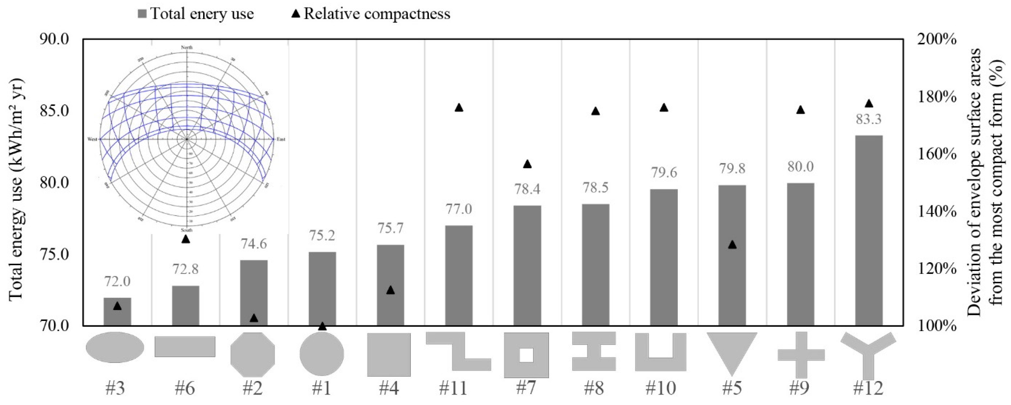
For the sub-tropical climate of Sydney, the results show that the ellipse (shape 3) has the lowest total energy use (72.0 kWh/m2), while the highest energy use was found for the Y shape (shape 12) (83.3 kWh/m2 or 15.7% higher than shape 3) (see Figure 5). According to the results, the amount of energy used for space cooling and fans is slightly lower in compact forms. The energy use for fans is calculated based on the supply air flow rate, pressure drop and fan efficiency. The supply fan only runs when either cooling or heating needs to be supplied to the zone. For elongated shapes, the increased length of ducts increases the energy use for fans due to higher pressure drops (compare shape 1 and shape 6). Contrary to this, a very deep plan like the circle shape would demand more electrical lighting; hence more cooling is needed to compensate the excessive internal gains by lighting and more energy is required for the distribution of cold air by fans.
The rectangle is the second most efficient shape after the ellipse. According to the results, the lowest cooling demand is around 32.3 kWh/m2 and 32.8 kWh/m2 for the ellipse and rectangle respectively (see Table 6). As can be seen, reducing the west-facing exposure is of great importance to limit overheating during the hot afternoon hours in summer. The compactness of the circle (shape 1) and the octagon (shape 2) are almost equal and therefore the energy use for cooling and fans are almost the same as well. Nonetheless, the 8-sided polygon resulted in 0.8 kWh/m2 lower energy use for electric lighting, which is closer to that of the rectangle and the ellipse.
The Z shape (shape 11) has the best energy performance among the linear shapes and even outperformed the courtyard and the triangle (that both have higher relative compactness). The extended top-side wing of the Z shape design helps to minimise afternoon solar gains by providing self-shading for a part of the north- and west-facing walls. The H shape (shape 8) also benefits from self-shading by means of external wings, however the distribution of windows being not as effective for daylighting as the U shape (shape 10).
After the circle, the triangle has the second largest energy use for electric lighting. The two sides of the inverted triangle shape are facing toward morning and evening solar radiation during summer. Low sun angles in the morning and evening are a source of glare when daylighting is provided through east- and west-facing windows. For all building models, high reflective blinds are adjusted inside the building to provide visual comfort for office occupants. Shading is on if the total daylight glare index exceeds the maximum glare index specified in the daylighting input for an office zone. The high amount of electric lighting demand for the triangle shape is probably caused by longer shading hours, so that less daylight can enter the space.
4.1.3. Tropical Climate
At latitudes closer to the equator, such as Singapore, the solar radiation is intense and to a great extent diffuse due to clouds. The sun rises almost directly in the east, peaks out nearly overhead, and sets in the west. This path does not change much throughout the year and the average air temperature is almost constant. On the one hand, a major design objective is reducing the heat transfer through the external surfaces exposed to outside high temperatures. For this purpose, a compact shape has less surface-to-volume ratio and can save more energy. On the other hand, the shape and orientation of the building should minimise the solar heat gains to lighten the cooling load. East- and west-facing walls and windows are a major factor in overheating. Therefore, the best orientation of the building for sun protection is along the east-west axis. The design objectives above are often contradictory.
In Singapore, cooling is paramount. Three shapes including the octagon, the ellipse and the circle require a lower amount of cooling energy and perform better than the others. The breakdown of annual energy consumption results for these three shapes indicates the superior function of the octagon shape for saving electric lighting which makes the octagon to have a better performance than the ellipse (+0.4%) and the circle (+0.5%) (see Figure 6 and Table 7).
The east and west-facing facades of the rectangle (shape 6) have the smallest portion of glazing area (glazing is only 12% on each side). Enclosing 1500 m2 of floor area by a rectangle shape will increase the building’s external surface area to 130% of the most compact form (shape 1). The results show an increase of total energy use by 3% compared to the most efficient form (shape 2).
The Y shape (shape 12) has the lowest energy performance. In tropical climates, cooling is the main end-use of energy; it considerably increases as the solar gains increase. In general, the risk of overheating is higher for buildings that have larger east- and west-facing walls. Having a wind turbine shape, about one third of the façade is irradiated half a day: during the morning the east façade is irradiated, and during the afternoon the west façade. As a result, shadings are required during a longer period to control the excessive glare, so that less daylight can enter the space. Moreover, the Y shape has the highest ratio of volume-to-external-surface area among all plan shapes (178%). Due to the aforementioned reasons, a high-rise building with a Y shape plan has the lowest performance of the investigated shapes, showing up to 11% increase in total energy use.
4.1.4. Suitability of Plan Shape for Architectural Design
In this study, energy efficiency was the main indicator for investigating the optimal plan shape. Other factors that might play a role for selecting the plan shape are space efficiency, natural ventilation, material use, structure, and aesthetic qualities [19]. Obviously, for two plan shapes that have almost the same energy performance, the priority would be with the one that can provide multiple benefits rather than mere energy efficiency. Therefore, it is worth to briefly discuss the suitability of plan shapes from different perspectives for architectural design of tall buildings.
In terms of space efficiency, the floor slab shape is of great importance. It influences the interior space planning and structural system. Generally, the planning and furnishing of right angled or asymmetrical shapes are easier than floor slabs with sharp corners, and curved or irregular shapes. Furthermore, the plan shape can affect the choice for the internal circulation pattern; hence the space efficiency. In case of H shape, + shape or Y shape more floor area is taken up by corridors due to longer circulation routes in comparison with compact forms with a central service core. This may reduce the percentage of usable space.
The application of natural ventilation has a major impact on selecting the plan shape. Narrow plan depth and aerodynamic building form (e.g., circle or ellipse) can assist in natural ventilation. The aerodynamic form encourages the flow of wind around the external envelope and into the building from a wide range of directions [17]. This also reduces turbulence around the building and improves pedestrian comfort at street level. The narrow plan depth facilitates the flow of air across the space and enhances the effectiveness of natural ventilation. In contrast, for buildings with a deep plan cross-ventilation can hardly occur, so that buildings require vertical shafts such as an atrium or solar chimney to facilitate natural ventilation. The application of large elements like that can minimise the efficient use of floor space [17].
Looking from the structural perspective and material use, asymmetrical compact forms, with the structural and functional core in the centre, are more resistant to lateral loads (e.g., due to wind or earthquakes) and require less material for the bracing structure [20]. On the other hand, the surface of curvilinear shapes (circle or ellipse) represents a smaller physical barrier against wind as compared to flat surfaces (square or rectangle), so that wind loads significantly reduce. Shape (size and configuration of the floor plan) is the most important cost driver for the construction of tall buildings. It can contribute up to 50% of total net cost due to its profound impact on the cost of structure and façade [21]. The two key ratios that represent the relationship between shape and cost are: wall-to-floor ratio and net-to-gross floor area ratio. The latter determining the efficient use of floor space. While the former represents the amount of wall area that is required to enclose a certain area of floor space. From a cost perspective, the lower wall-to-floor ratio is better, so that a compact shape is the most economical choice [21].
Elongated floor plates that have an increased perimeter area (or deep plan shapes that have a central atrium) are favouring shapes for daylight access and views out in workplaces [17]. However, the elongated sides should not be oriented toward east or west; since there is a risk of overheating and glare discomfort. Curvilinear shapes can provide a panoramic view to outside and improve the aesthetic qualities of design. Curvilinear shapes might also contribute in building’s energy efficiency and provide more sustainable solutions [22].
4.2. Plan Depth and Building Energy Performance
The optimal balance of plan depth and building external surface area for energy efficiency of a 40-storey office building was investigated by modelling seven aspect ratios of an equiangular four-sided shape with 1500 m2 of office area per floor (Table 8). The aspect ratio is a measure of the building’s footprint that describes the proportional relationship between its length and its width (x:y). For an equal floor area, changing the aspect ratio will result in different external surface area and plan depth. An aspect ratio of 1:1 represents a square plan shape which has the lowest envelope area and the largest plan depth (38.7 m) among the rectangular shapes. Other aspect ratios have been made by extending the length of the floor plans along the east-west axis. So, the long sides of the building will face in the direction of north and south.
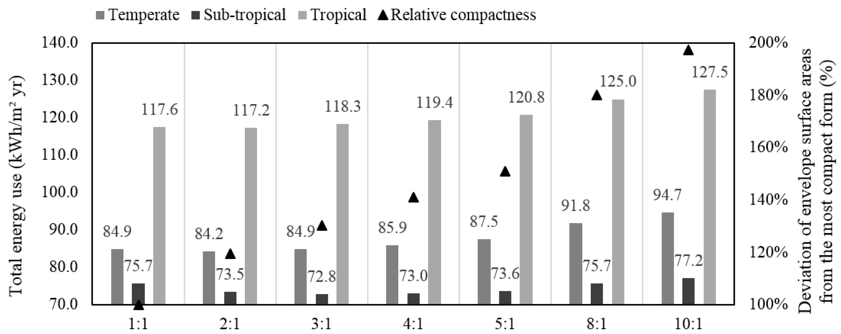
The building performance simulation results of the seven plan aspect ratios are provided in Figure 7 and Appendix A. In temperate climates, the most compact form (1:1) requires the lowest amount of heating and cooling energy. On the other hand, the deeper the plan, the harder it will be to naturally light the interior space, so that the electric lighting demand would be higher. Therefore, the 2:1 shape is slightly better than the 1:1 shape in the temperate climate. A large deviation in total energy use by about 12.8% can be observed between the most efficient (2:1) and least efficient (10:1) plan in the temperate climate. Having a plan aspect ratio of 1:1 or 3:1 can result in a minor 0.8% increase of the total energy use from the most efficient one.
In sub-tropical climates, the impact of plan depth on total energy use is less significant both in relative value (6%) and in absolute value (4.4 kWh/m2). A plan aspect ratio between 2:1 and 5:1 is ideal in the sub-tropical climate of Sydney. Although reducing the external shell is critical for energy saving in tropical climates, reducing the plan depth can improve the access to daylight and compensate for the extra cooling energy demand due to solar gains. Consequently, the same as in the temperate climate, a plan ratio of 2:1 is the most efficient aspect ratio in the tropical climate, while a square plan shape (1:1) could be the next alternative for good energy-based design in tropical climates.
4.3. Plan Orientation and Building Energy Performance
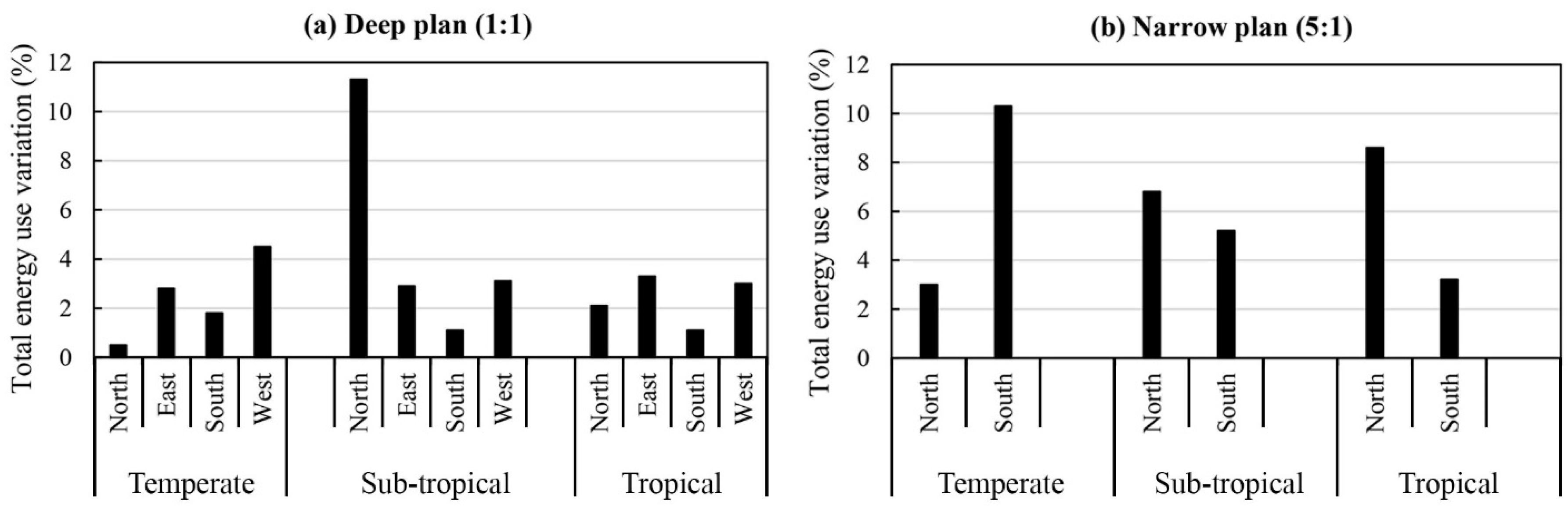
In order to investigate the effect of plan orientation on energy consumption, four aspect ratios (1:1, 3:1, 5:1 and 10:1) from the previous section were modelled in four orientations; 0°, 45°, 90° and 135°. A zero-degree orientation means that the long sides of the building will face in the direction of north and south. Other orientations were made by rotating the buildings clockwise with respect to the north. As a result, a total number of 14 models were simulated and their energy performance analysed. A zero-degree orientation always resulted in the lowest energy consumption, while rotating the building 90° increased the energy use of the building to a large extent (Figure 8). In that orientation (0°) the building can make optimal use of solar gains on south facades in colder climates in winter and optimally keep out solar radiation in the early morning or afternoon in warm climates or in colder climates in summer.
The largest impact of orientation was observed for the sub-tropical climates (up to 32%) when the building is oriented at 90° and for the minimum plan depth (10:1). The effect of changing orientation is smaller for the temperate and tropical climates when the worst orientation is adopted compared to the optimal results; showing +15% and +8% increase respectively. Compact forms (deep plan buildings) are less sensitive to changes in orientation. In all climates, a building oriented 45° consumed less energy for electric lighting than one oriented 0° when the building has a deep plan (1:1). However, the increased overall energy demand caused by extra heating and cooling loads beat the energy saving in electric lighting. Our results are in good agreement with the findings in Florides, et al. [23]. They found that the thermal loads of a square-shaped building reached its minimum value when facades are directly oriented toward the four cardinal directions. Our findings also determined that a 0° rotation from the north is the optimal orientation for gaining heat in cooler climates (temperate) and for controlling solar radiation in warmer climates (sub-tropical and tropical); this is in line with the findings of earlier studies [24,25,26].
4.4. Window-to-Wall Ratio and Building Energy Performance
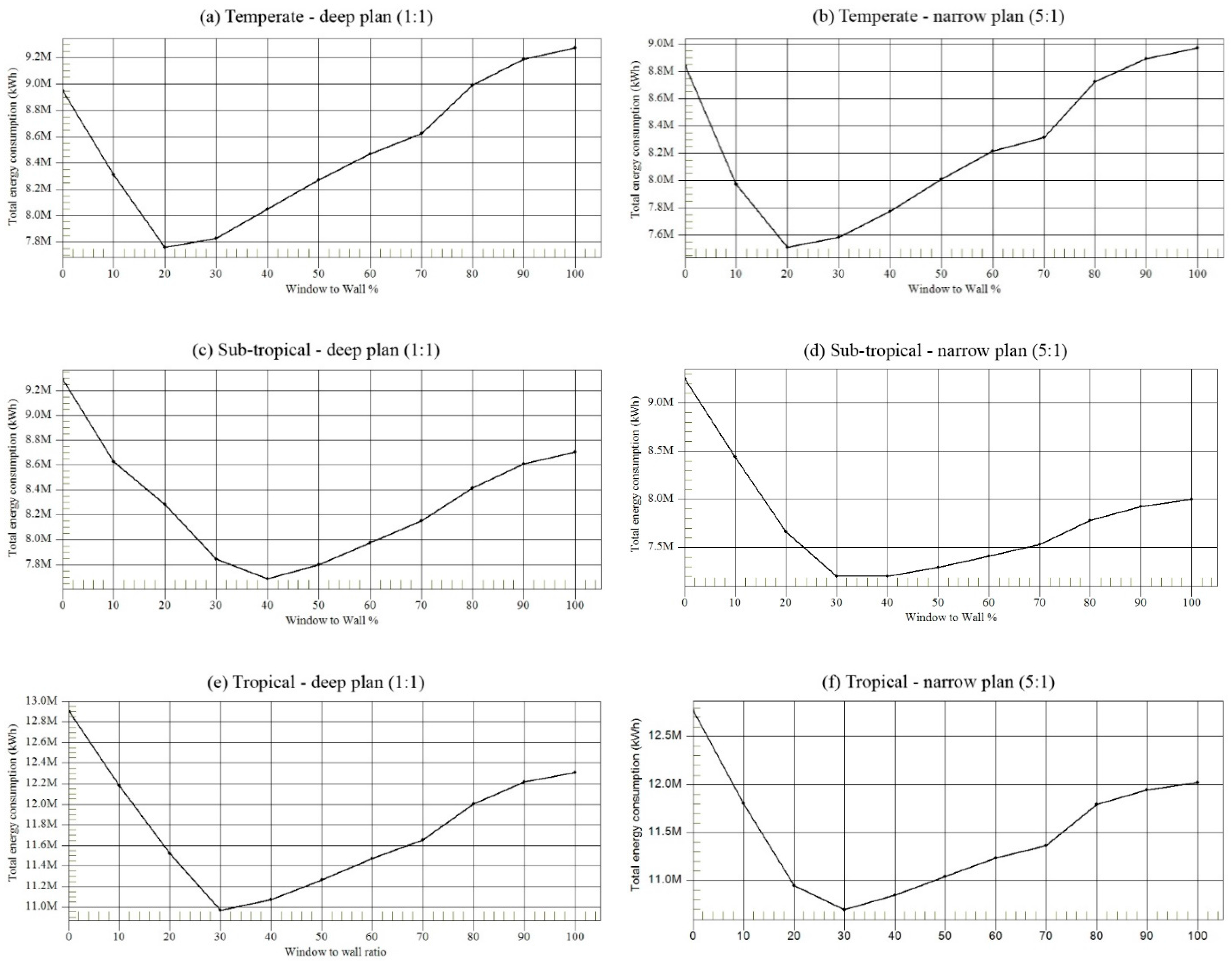
Simulations were performed on a 40-storey office building to investigate the optimal size of the windows in temperate, sub-tropical and tropical climates. Since plan depth is a major determinant in finding the optimal solution, two plan scenarios were selected: a deep plan (1:1) and a narrow plan (5:1). Discrete window-to-wall ratio variations were studied, starting with a minimum value of 0% and increase with 10% increments to a maximum of 100%. For the deep plan scenario, the windows were distributed evenly among all directions. For the narrow plan scenario, the north- and south-facing walls (long sides of the building) are the focus of the investigation, while the east- and west-facing walls have no glazing.
Results for the optimal window-to-wall ratios are shown in Appendix B. The energy efficiency indicator is the annual total energy use for heating, cooling, electric lighting and fans. Although there is an optimal WWR for each climate, the recommended values can be classified in four categories based on their degree of efficiency as shown in Figure 9. The most ideal WWR can be found in a relatively narrow range in which the total energy use deviates by less than 1% from the optimal results.
The energy consumption trend shows that in a temperate climate a window-to-wall ratio between 20% and 30% would result in the highest energy-efficiency for both the narrow and the deep plan due to lower heat transfer through the façade during winter and summer. Through using a similar approach—the integrated thermal and daylighting simulations in the temperate oceanic climates—earlier studies obtained the optimal WWR at slightly different ranges. Kheiri [27] found the optimal value in the range of 20–32% for a building that was featured by a low-performance façade (U values for windows and walls were 2.4 W/m2K and 2.6 W/m2K respectively) and had no shading system. However, Goia et al. [28] found the optimal value in the range of 35–45% through the integration of external solar shading devices with a high-performance façade (U values for windows and walls were 0.7 W/m2K and 0.15 W/m2K respectively). Therefore, it can be inferred that the optimal WWR value depends on the envelope properties employed in the simulations and can influence the results to some extent. The higher thermal resistance of the envelope, the lower impact of WWR on total energy use; hence, building can take advantage of larger windows for energy saving. Furthermore, our findings show that for WWR values smaller than 20%, the energy use for electric lighting incredibly increases. In a temperate climate, the upper limit of the recommended WWR is 60%; higher values result in up to 10% increase in total energy consumption due to additional transmission heat losses through the façade.
In a sub-tropical climate, the optimal WWR value is 35–45% for a deep plan and 30–40% for a narrow plan building. WWR variations that contain average performance (1–5% deviation) cover a relatively big range. For example, in case of the narrow plan scenario, window-to-wall ratios between 25–30% and 40–70% have average performance, but in a temperate climate this range limits to between 10–20% and 30–40%. Since the heating energy required is not significant for buildings in sub-tropical climates, a larger window area can result in a smaller demand for electric lighting; hence a better total energy performance. However, values higher than 80% and 90% are not recommended, respectively for a deep plan and narrow plan building because these have to high solar heat gains.
In a tropical climate, the optimal window-to-wall ratio is higher than that in a temperate climate but lower than in a sub-tropical climate. It is in a range of 30–40% for a deep plan and 25–35% for a narrow plan building. According to Figure 3, in the tropical climate, the share of electric lighting loads from the total end-use of energy is lower than in the sub-tropical climate. As a result, the energy savings for electric lighting (due to higher WWR values) in the tropical climate cannot be as much as in the sub-tropical climate. In addition, the difference between the indoor and outdoor air temperature in the tropical climate is not as high as in the temperate climate. So in the tropical climate, buildings can have a wider range of WWR values compared to that in temperate regions; especially when the proper type of glazing (low U value and solar heat gain coefficient) and the shading systems are employed in the facades for solar gain control.
4.5. Window Orientation and Building Energy Performance
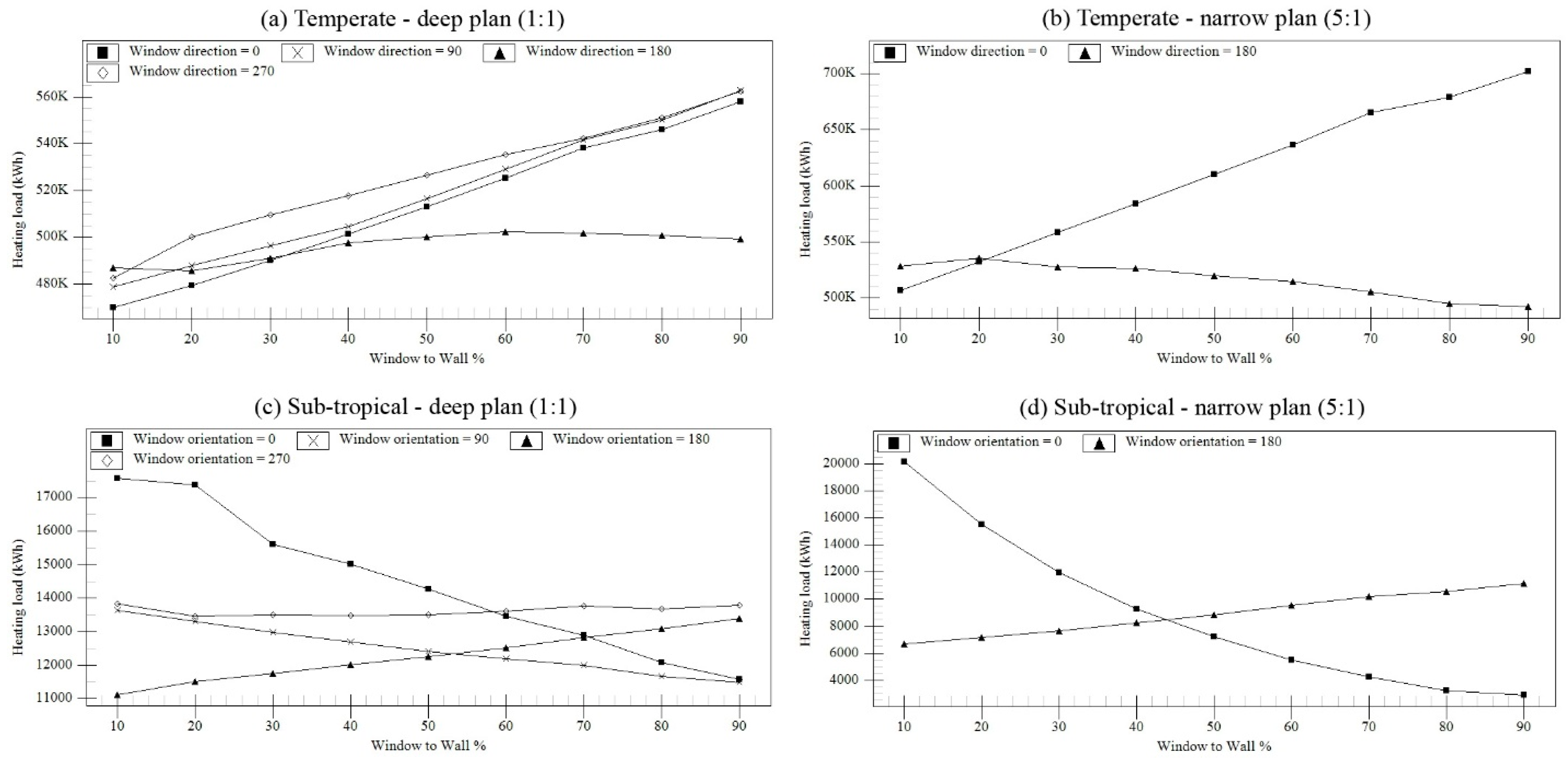
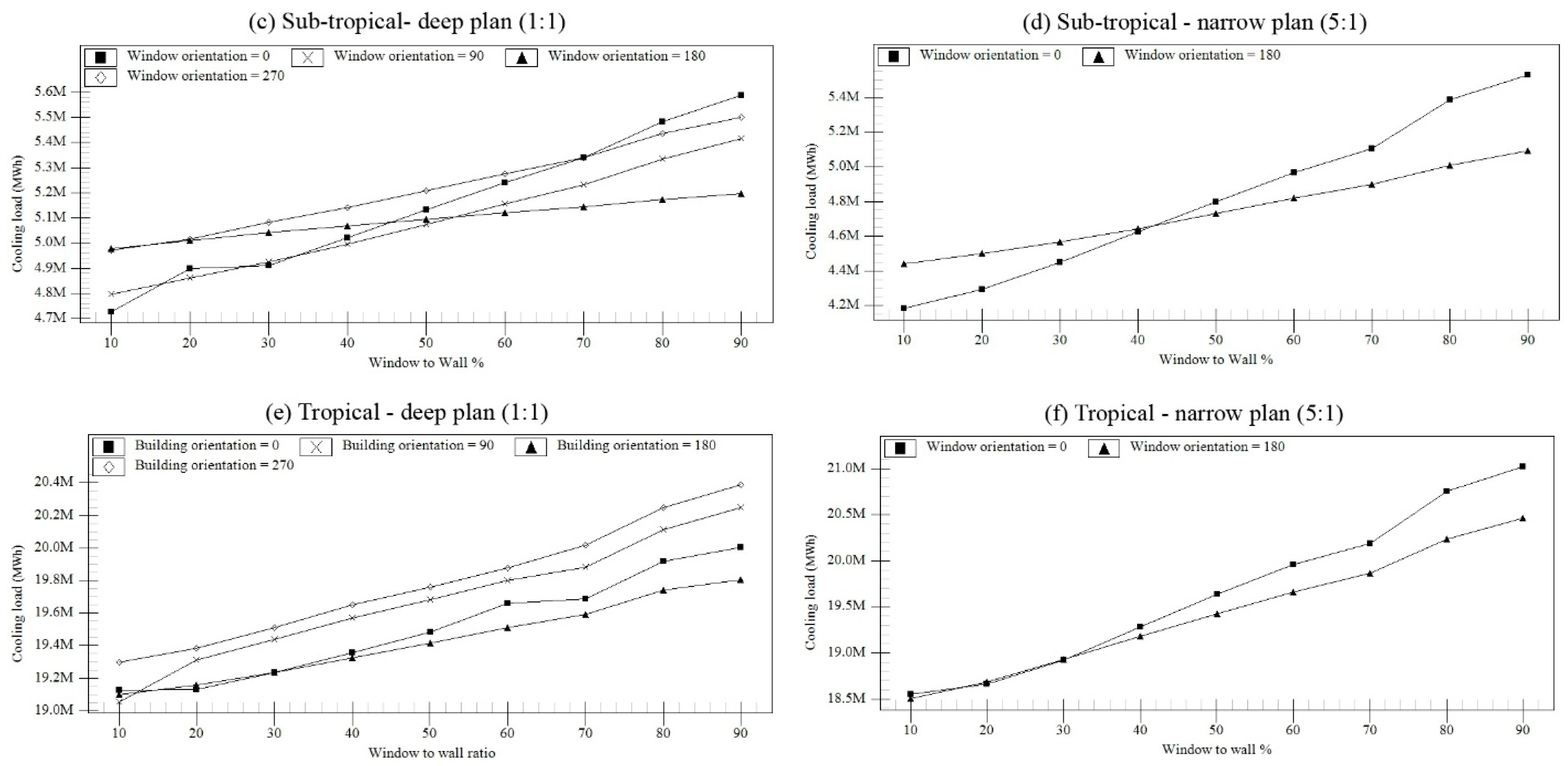
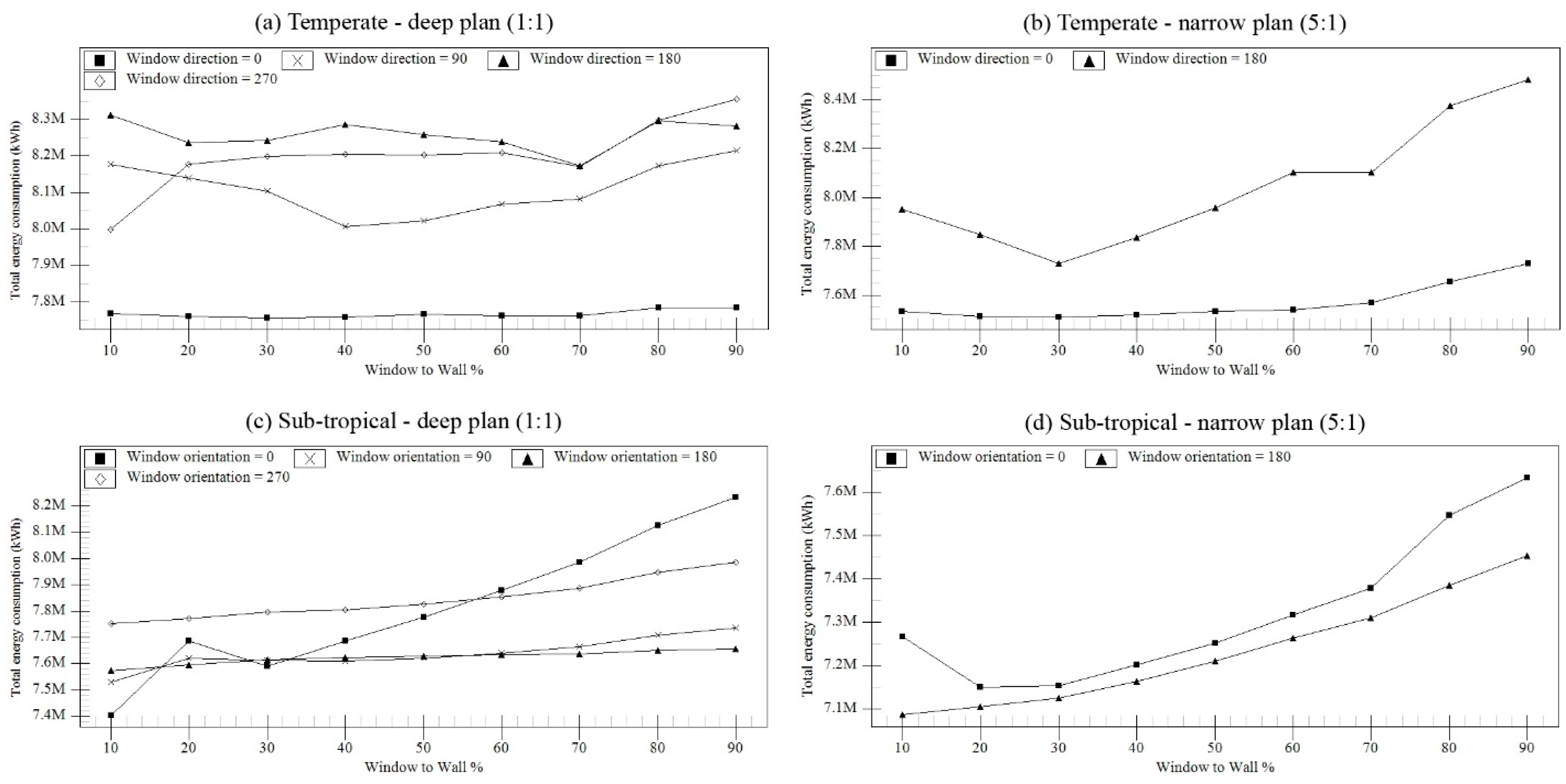
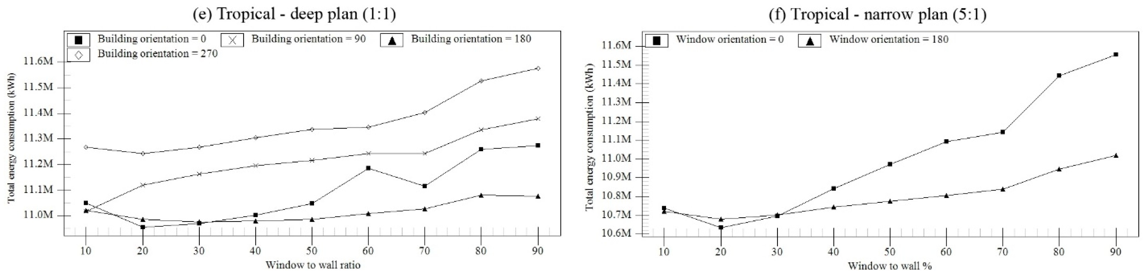
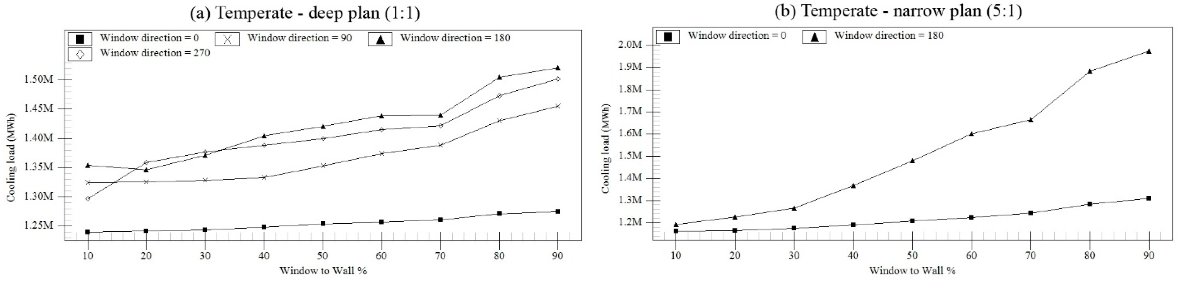
In the previous sub-section, optimal WWR values of the façade, were determined for two plan scenarios regardless of the window orientation. In this part of the paper, the effect of window orientation on the total energy demand of the building will be investigated. Discrete window-to-wall ratio variations were tested, ranging from 10% to 90%, in incremental steps of 10%. One side of the plan was the subject of change on every iteration while the WWR for the other three sides was kept at the optimal value that was previously determined. The inputs of the simulation for the optimal WWR are 20% for the temperate climate, 40% for the sub-tropical climate, and 30% for the tropical climate.
The investigation was carried out on the four main orientations of the deep plan scenario and the two north- and south-facing facades of the narrow plan scenario. For the purpose of readiness, few graphs containing simulation results for the effect of window orientation on total energy use and energy end-uses (heating and cooling) are not shown in the text, but they can be found in Appendix C, Appendix D and Appendix E. Sensitivity of different window orientations to a change in the WWR value was analysed in regards to total energy use variations and the results are provided in Table 9. Accordingly, the recommended values of WWR for different orientations and climates are summarised in Figure 10. The efficiency indicator for defining the recommended values is the total of all energy end-uses. As can be seen in Table 9, the acceptable window-to-wall ratio can range from 10% to 90% depending on the effectiveness of different window orientations for energy saving. For WWR increments of less than 10%, the average energy performance from two consecutive WWR values was obtained. Recommended values represent a range of WWR in which the deviation of total energy use is smaller than 1% from the optimal value in each orientation.
In temperate climates, the north-facing façade was found to be the least sensitive orientation, with no significant variation in energy use when relatively high insulation values were included in the simulations for windows (U value: 1.50 W/m2K) and opaque surfaces (U value: 0.35 W/m2K), and indoor blinds were adjusted only for glare control. In case of a deep plan, the ideal WWR for north-orientated windows can be found in a considerably wide range (10–90%) in which the deviation of total energy use is less than 1% from the optimal results. For the south-facing façade, the best energy performance is achieved with large windows when WWR is in a range of 65–75%. The optimal WWR for the west-facing façade is the lowest value of the investigated WWR range. According to Figure A3a and Figure A4a, the heating and cooling energy demand both increased significantly when the WWR percentage changed from 10% to 20%. The east-facing façade does not increase the cooling energy demand as much as the west-facing façade and does not contribute to capturing solar thermal energy on winter days as much as the south-facing exposure; therefore, the optimal range of WWR is 35–60%. In case of a narrow floor plan, lower values of the optimal WWR are achieved for the north- and south-facing facades due to a higher impact of the cooling energy use in the total energy balance. A wrong selection of WWR in the south-facing façade of a narrow floor plan can cause a greater increase of the cooling energy use (up to 68%) than of a deep plan building (13%).
In sub-tropical climates and for the deep plan scenario, the north-facing façade is the most sensitive orientation to a change in the WWR value, showing up to 11% deviation in total energy use. In order to achieve the highest energy performance (<1% deviation) it is important to reduce the size of east- and west-facing windows (10–20%) to protect the building against overheating, while for the south-facing exposure the total energy use is barley influenced by the WWR value. In case of a narrow plan building, the north- and south-facing facades present relatively similar trends and the recommended WWR ranges for those exposures are very close too (around 10–40%).
For all orientations in tropical climates, the cooling energy use is the driving force for selecting the recommended WWR range. The highest increases in cooling energy use are observed when a high WWR value is adopted for the west and east orientation, respectively. Therefore, the east- and west-facing walls should particularly avoid high WWR values. In the tropics and during mid-day, the building surface that receives the most sun is the roof since the sun paths a high arc across the sky. In case of a deep plan building, a wrong selection of WWR in north- and south-facing facades can cause a lower increase in the total energy use (+2.1% and +1.1%, respectively). For a building with a plan aspect ratio of 5:1, the recommended WWR values are found in a relatively narrow range; 10–35% for north-facing façade and 10–55% for south-facing façade.
4.6. Research Limitations and Recommendations
There are several points that need to be further discussed for the proper use of findings and for the future development of this research. First of all, single-zone open-plan layout offices were defined for the entire floor space in all building models. Using one activity template has both advantages and disadvantages. On the positive side, it reduces the model’s complexity, hence speeds up the simulation. In contrast, design potentials that some geometries might have in comparison to others, and their consequent effect on energy consumption cannot be reflected (e.g., usability of space). Furthermore, an increase of usable space can increase the internal gains due to occupancy, computers and lighting, which might have impact on the heating and cooling demands.
The optimal design solution depends on the exact set of variables for the properties of the building and the operation details. A sensitivity analysis was performed to obtain the glazing types and shading strategies for each of the climates used in this study. It was found that external shading performed better in terms of energy saving; however, the vulnerability of external shadings to high wind speeds at high levels in tall buildings is an important barrier for the application of them. Moreover, indoor shading devices are not prone to damage due to wind. They, however, reduce the view out and increase the need of artificial lighting and cooling. Hence, all simulations were carried out by using indoor blinds to control only glare. This means that cooling demands were probably less favourable than in reality.
Amsterdam, Sydney and Singapore were the representative cities for the investigation of the impact of geometric factors on energy use in the three main climate categories where the majority of tall buildings are being constructed. In general, for each latitude, the course of the sun and local microclimate conditions might influence a building’s performance to some extent, so it is important to use the specific site location data as input for the simulations when the aim is finding the optimal results. The main objective of this study was to propose early-stage design considerations for the energy-efficiency of high-rise office buildings in three specific climates, so that these can be used to increase the awareness of designers regarding the consequences on energy consumption of decisions in the early phases of the design process.
Small to significant deviations may exist between the simulated and actual energy consumption for buildings. According to Wang et al. [29] these deviations can be attributed to uncertainties related to the accuracy of the underlying models, input parameters, actual weather data and building operation details. There are some uncertainties related to the accuracy of simulation tool to consider thermal performance of curved shapes, and the optimal choice of number of timesteps per hour for heat balance model calculation. Furthermore, high-rise buildings are exposed to variable micro-climate conditions that changes gradually with the increase in building height. In tall buildings, the top levels are exposed to higher wind speeds and slightly lower air temperature as compared to the levels that are within the urban canopy. Additionally, at the higher altitude, the stack effect and wind pressures increase so that the air leakage through the building envelope and the consequent heat losses and gains might vary along the height. When using the weather data from a certain height, the impact of changing outdoor conditions and infiltration rates along the height could not be taken into account.
Finally, the investigation highlights that focusing on just one entry of the total energy balance is not correct and may lead to wrong conclusions. Therefore, determination of the optimal building geometry factor requires the analysis of heating, cooling, electric lighting and fans altogether, since these can be affected by the design of the building.
5. Conclusions
The study presented in this paper investigated the effect of basic geometry factors on energy efficiency of high-rise office buildings in temperate, sub-tropical and tropical climates. Four geometric factors were the subject of investigation, which included plan shape, plan aspect ratio, building orientation and windows (percentage and distribution). A large number of energy simulations were performed using EnergyPlus as part of DesignBuilder. The results of the total annual energy consumption were used to define the optimal building geometry for each climate. This study shows the following:
- The effect of plan shape on building energy consumption is the highest in the sub-tropical climate (15.7%), and is lowest in the temperate climate (12.8%) and tropical climate (11.0%). The ellipse was found to be the ideal plan shape in all climates. It is the most efficient form in temperate and sub-tropical climates and the second efficient form in tropical climates after the octagon. Furthermore, the Y shape is the least efficient form in all climates.
- The effect of plan depth on total energy consumption is more dominant in the temperate climate (12.8%) than in the tropical (8.8%) and sub-tropical climate (6.0%). The optimal range of plan aspect ratio are 1:1 to 3:1 in Amsterdam, 3:1 to 4:1 in Sydney, and 1:1 to 3:1 in Singapore.
- In all climates, a rotation 0° from the north was found to be the ideal orientation for energy efficiency. In addition, a 90° rotation from the north is the least efficient orientation in all climates and for all plan aspect ratios (1:1 to 10:1) with an equiangular four-sided plan shape.
- Assuming that windows are equally distributed across building orientations, for a deep plan design, the optimal range of the window-to-wall ratio is 20–30% in the temperate climate, 35–45% in the sub-tropical climate, and 30–40% in the tropical climate. For a narrow plan design (with no glazing for the east- and west-facing walls), the optimal range is 5% lower, except for the temperate climate, which has the same values as for the deep plan design.
- The investigation also highlights the most sensitive orientations that potentially increase the total energy use (relative value) to a large extent for a wrong selection of WWR in different climates; those include the west-facing exposure in temperate climates (+4.5%), the north-facing exposure in sub-tropical climates (+11.3%), and the two facades facing east and west in tropical climates (up to 3.3%). Furthermore, the recommended WWR values are pointed out for different orientations and climates (see Table 9).
The impact of geometric factors on energy-efficiency of high-rise office buildings in the three climates is summarised in Table 10. The recommended design options are classified according to their degree of energy performance under three categories: remarkable energy saving, average energy saving, and low energy saving. If the deviation of total energy use is greater than 10% from the optimal solution, the design alternative will be considered as not recommended. The results could be of assistance to make energy-wise decisions in the early phases of the design process.
Acknowledgments
The authors would like to thank the anonymous reviewers for their helpful and constructive comments that greatly contributed to improving the final version of the paper. They would also like to thank the Editors for their support during the review process.
Author Contributions
All authors contributed extensively to the work presented in this paper. Babak Raji carried out simulations, collected data and prepared drafts. Martin J. Tenpierik and Andy van den Dobbelsteen supervised data analysis and edited the manuscript. All authors discussed the results and implications and commented on the manuscript at all stages.
Conflicts of Interest
The authors declare no conflict of interest.
Appendix A

Table A1.
Breakdown of annual energy consumption per conditioned area for seven plan aspect ratios (WWR= 50%) in: (a) Amsterdam, (b) Sydney, and (c) Singapore.
Table A1.
Breakdown of annual energy consumption per conditioned area for seven plan aspect ratios (WWR= 50%) in: (a) Amsterdam, (b) Sydney, and (c) Singapore.
| (a) Amsterdam | ||||||
| Plan Aspect Ratio | Breakdown of Annual Total Energy Demand | Annual Total Energy Demand | ||||
| Heating/Conditioned Area (kW h/m2) | Cooling/Conditioned Area (kW h/m2) | Lighting/Conditioned Area (kW h/m2) | Fan/Conditioned Area (kW h/m2) | Total/Conditioned Area (kW h/m2) | Percentile Difference (%) | |
| 1:1 | 15.2 | 23.5 | 17.5 | 28.7 | 84.9 | 0.8% |
| 2:1 ® | 15.3 | 23.6 | 16.7 | 28.6 | 84.2 | - |
| 3:1 | 15.5 | 24.2 | 15.8 | 29.4 | 84.9 | 0.8% |
| 4:1 | 15.6 | 24.9 | 15.0 | 30.4 | 85.9 | 2.1% |
| 5:1 | 15.9 | 25.8 | 14.4 | 31.4 | 87.5 | 3.9% |
| 8:1 | 16.7 | 27.8 | 13.0 | 34.3 | 91.8 | 9.0% |
| 10:1 | 17.2 | 29.0 | 12.4 | 36.0 | 94.7 | 12.4% |
| (b) Sydney | ||||||
| Plan Aspect Ratio | Breakdown of Annual Total Energy Demand | Annual Total Energy Demand | ||||
| Heating/conditioned Area (kW h/m2) | Cooling/Conditioned Area (kW h/m2) | Lighting/Conditioned Area (kW h/m2) | Fan/Conditioned Area (kW h/m2) | Total/Conditioned Area (kW h/m2) | Percentile Difference (%) | |
| 1:1 | 0.4 | 34.2 | 12.6 | 28.4 | 75.7 | 4.0% |
| 2:1 | 0.3 | 33.3 | 12.3 | 27.6 | 73.5 | 1.0% |
| 3:1 ® | 0.3 | 32.8 | 11.7 | 28.0 | 72.8 | - |
| 4:1 | 0.2 | 33.5 | 11.3 | 28.0 | 73.0 | 0.3% |
| 5:1 | 0.2 | 34.0 | 10.9 | 28.5 | 73.6 | 1.1% |
| 8:1 | 0.2 | 35.3 | 10.2 | 30.0 | 75.7 | 4.0% |
| 10:1 | 0.2 | 36.1 | 10.0 | 30.9 | 77.2 | 6.0% |
| (c) Singapore | ||||||
| Plan Aspect Ratio | Breakdown of Annual Total Energy Demand | Annual Total Energy Demand | ||||
| Heating/Conditioned Area (kW h/m2) | Cooling/Conditioned Area (kW h/m2) | Lighting/Conditioned Area (kW h/m2) | Fan/Conditioned Area (kW h/m2) | Total/Conditioned Area (kW h/m2) | Percentile Difference (%) | |
| 1:1 | 0.0 | 76.5 | 11.3 | 29.5 | 117.6 | 0.3% |
| 2:1 ® | 0.0 | 76.7 | 10.8 | 29.7 | 117.2 | - |
| 3:1 | 0.0 | 77.8 | 10.2 | 30.3 | 118.3 | 0.9% |
| 4:1 | 0.0 | 78.7 | 9.5 | 31.2 | 119.4 | 1.9% |
| 5:1 | 0.0 | 79.7 | 9.0 | 32.1 | 120.8 | 3.0% |
| 8:1 | 0.0 | 82.6 | 8.1 | 34.3 | 125.0 | 6.6% |
| 10:1 | 0.0 | 84.2 | 7.7 | 35.7 | 127.5 | 8.8% |
® Reference (the most efficient design option).
Appendix B
Figure A1.
The optimal percentage of window-to-wall ratio for two plan types (1:1 and 5:1) in Temperate, Sub-tropical, and Tropical climates.
Figure A1.
The optimal percentage of window-to-wall ratio for two plan types (1:1 and 5:1) in Temperate, Sub-tropical, and Tropical climates.
Appendix C
Figure A2.
The optimal percentage of window-to-wall ratio in different orientations for two plan types (deep and narrow) in three climates.
Figure A2.
The optimal percentage of window-to-wall ratio in different orientations for two plan types (deep and narrow) in three climates.
Appendix D
Figure A3.
Relationship between energy use for heating and window-to-wall ratio in different orientations for two plan scenarios (deep and narrow) in temperate, sub-tropical, and tropical climates.
Figure A3.
Relationship between energy use for heating and window-to-wall ratio in different orientations for two plan scenarios (deep and narrow) in temperate, sub-tropical, and tropical climates.

Appendix E
Figure A4.
Relationship between energy use for cooling and window-to-wall ratio in different orientations for two plan scenarios (deep and narrow) in temperate, sub-tropical, and tropical climates.
Figure A4.
Relationship between energy use for cooling and window-to-wall ratio in different orientations for two plan scenarios (deep and narrow) in temperate, sub-tropical, and tropical climates.

References
- Bragança, L.; Vieira, S.M.; Andrade, J.B. Early stage design decisions: The way to achieve sustainable buildings at lower costs. Sci. World J. 2014. Available online: http://www.hindawi.com/journals/tswj/2014/365364/abs/ (accessed on 22 December 2016.).
- Attia, S.; De Herde, A. Design decision tools for zero energy buildings. In Proceedings of the 27th Conference on Passive and Low Energy Architecture, Louvain-la-Neuve, Belgium, 13–15 July 2011; pp. 77–82. [Google Scholar]
- Athienitis, A.; Attia, S. Strategic design, optimization, and modelling issues of net-zero energy solar buildings. In Proceedings of the Eurosun 2010, Graz, Austria, 28 September–1 October 2010. [Google Scholar]
- Pessenlehner, W.; Mahdavi, A. Building morphology, transparence, and energy performance. In Proceedings of the Eighth International IBPSA Conference, Eindhoven, The Netherlands, 2003; pp. 1025–1032. [Google Scholar]
- Depecker, P.; Menezo, C.; Virgone, J.; Lepers, S. Design of buildings shape and energetic consumption. Build. Environ. 2001, 36, 627–635. [Google Scholar] [CrossRef]
- Ourghi, R.; Al-Anzi, A.; Krarti, M. A simplified analysis method to predict the impact of shape on annual energy use for office buildings. Energy Convers. Manag. 2007, 48, 300–305. [Google Scholar] [CrossRef]
- AlAnzi, A.; Seo, D.; Krarti, M. Impact of building shape on thermal performance of office buildings in kuwait. Energy Convers. Manag. 2009, 50, 822–828. [Google Scholar] [CrossRef]
- Choi, I.Y.; Cho, S.H.; Kim, J.T. Energy consumption characteristics of high-rise apartment buildings according to building shape and mixed-use development. Energy Build. 2012, 46, 123–131. [Google Scholar] [CrossRef]
- Susorova, I.; Tabibzadeh, M.; Rahman, A.; Clack, H.L.; Elnimeiri, M. The effect of geometry factors on fenestration energy performance and energy savings in office buildings. Energy Build. 2013, 57, 6–13. [Google Scholar] [CrossRef]
- Kämpf, J.H.; Robinson, D. Optimisation of building form for solar energy utilisation using constrained evolutionary algorithms. Energy Build. 2010, 42, 807–814. [Google Scholar] [CrossRef]
- Yi, Y.K.; Malkawi, A.M. Site-specific optimal energy form generation based on hierarchical geometry relation. Autom. Constr. 2012, 26, 77–91. [Google Scholar] [CrossRef]
- Wang, W.; Rivard, H.; Zmeureanu, R. An object-oriented framework for simulation-based green building design optimization with genetic algorithms. Adv. Eng. Inform. 2005, 19, 5–23. [Google Scholar] [CrossRef]
- Magnier, L.; Haghighat, F. Multiobjective optimization of building design using trnsys simulations, genetic algorithm, and artificial neural network. Build. Environ. 2010, 45, 739–746. [Google Scholar] [CrossRef]
- Yi, Y.K.; Malkawi, A.M. Optimizing building form for energy performance based on hierarchical geometry relation. Autom. Constr. 2009, 18, 825–833. [Google Scholar] [CrossRef]
- Malkawi, A.M. Developments in environmental performance simulation. Autom. Constr. 2004, 13, 437–445. [Google Scholar] [CrossRef]
- US Department of Energy. Weather Data. Available online: https://energyplus.net/weather (accessed on 20 September 2016).
- Wood, A.; Salib, R. Natural Ventilation in High-Rise Office Buildings, Ctbuh Technical Guides; Routledge: New York, NY, USA, 2013. [Google Scholar]
- Straube, J.F.; Burnett, E.F.P. Building Science for Building Enclosures; Building Science Press: Westford, MA, USA, 2005. [Google Scholar]
- Raji, B.; Tenpierik, M.J.; van den Dobbelsteen, A. A comparative study: Design strategies for energy-efficiency of high-rise office buildings. J. Green Build. 2016, 11, 134–158. [Google Scholar] [CrossRef]
- Van den Dobbelsteen, A.; Thijssen, S.; Colaleo, V.; Metz, T. Ecology of the building geometry-environmental performance of different building shapes. In Proceedings of the CIB World Building Congress 2007; CIB/CSIR. Cape Town, South Africa, 14–17 May 2007; pp. 178–188. [Google Scholar]
- Watts, S. Tall building economics. In The Tall Buildings Reference Book; Parker, D., Wood, A., Eds.; Routledge: New York, NY, USA, 2013; pp. 49–70. [Google Scholar]
- Wilkinson, C. Aesthetics, symbolism and status in the twenty-first century. In The Tall Buildings Reference Book; Parker, D., Wood, A., Eds.; Routledge: New York, NY, USA, 2013; pp. 33–40. [Google Scholar]
- Florides, G.A.; Tassou, S.A.; Kalogirou, S.A.; Wrobel, L.C. Measures used to lower building energy consumption and their cost effectiveness. Appl. Energy 2002, 73, 299–328. [Google Scholar] [CrossRef]
- Pacheco, R.; Ordóñez, J.; Martínez, G. Energy efficient design of building: A review. Renew. Sustain. Energy Rev. 2012, 16, 3559–3573. [Google Scholar] [CrossRef]
- Mingfang, T. Solar control for buildings. Build. Environ. 2002, 37, 659–664. [Google Scholar] [CrossRef]
- Abanda, F.H.; Byers, L. An investigation of the impact of building orientation on energy consumption in a domestic building using emerging bim (building information modelling). Energy 2016, 97, 517–527. [Google Scholar] [CrossRef]
- Kheiri, F. The relation of orientation and dimensional specifications of window with building energy consumption in four different climates of koppen classification. Researcher 2013, 5, 107–115. [Google Scholar]
- Goia, F.; Haase, M.; Perino, M. Optimizing the configuration of a façade module for office buildings by means of integrated thermal and lighting simulations in a total energy perspective. Appl. Energy 2013, 108, 515–527. [Google Scholar] [CrossRef]
- Wang, L.; Mathew, P.; Pang, X. Uncertainties in energy consumption introduced by building operations and weather for a medium-size office building. Energy Build. 2012, 53, 152–158. [Google Scholar] [CrossRef]
Figure 1.
Methodological scheme of research.

Figure 2.
Mean monthly values of dry-bulb temperature and solar radiation in: (a) Amsterdam; (b) Sydney; and (c) Singapore for the year 2002 [16].
Figure 2.
Mean monthly values of dry-bulb temperature and solar radiation in: (a) Amsterdam; (b) Sydney; and (c) Singapore for the year 2002 [16].
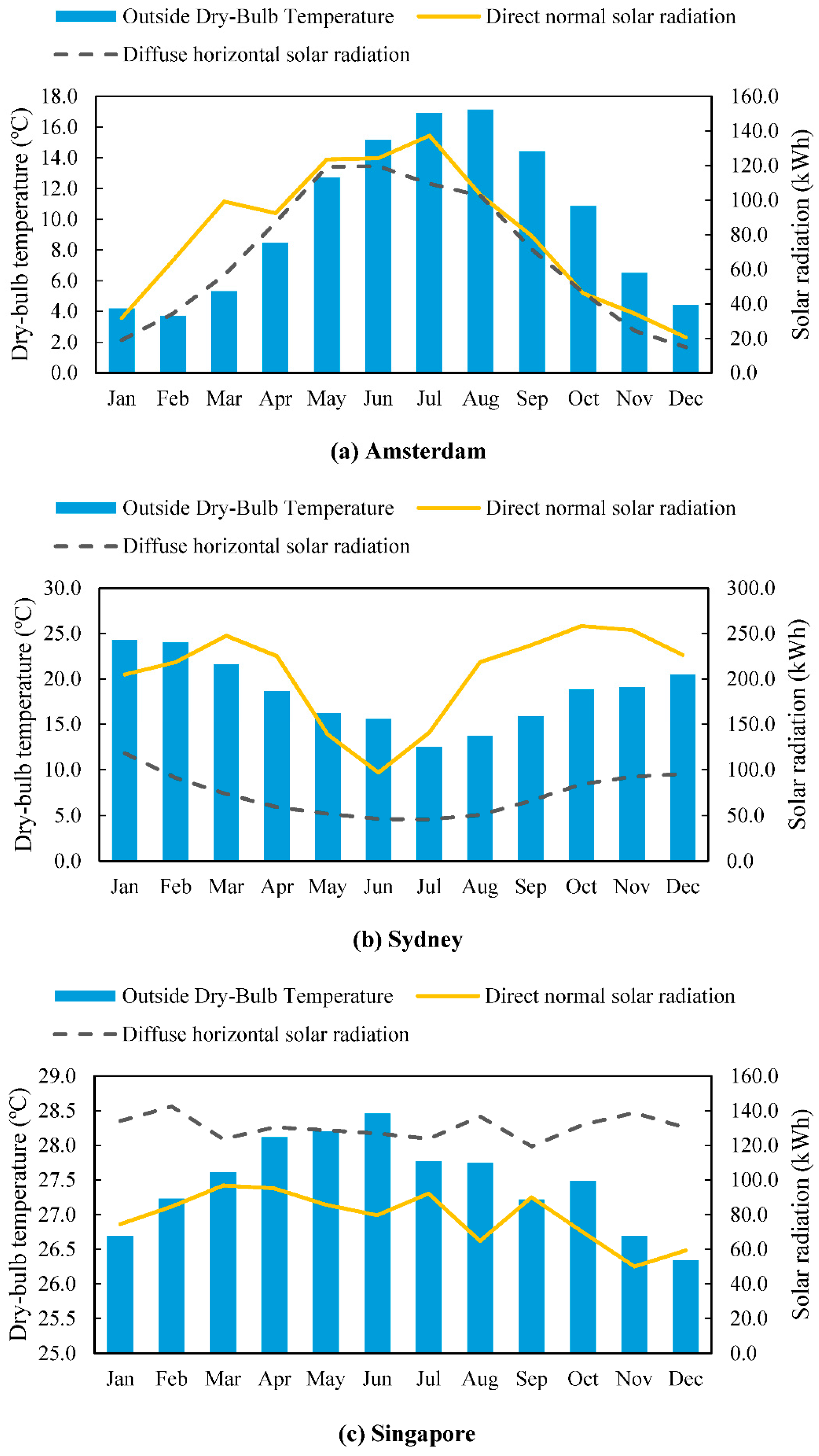
Figure 3.
Breakdown of the total energy use in a simulated 40-storey office building with rectangular floor plan (3:1) in Amsterdam, Sydney, and Singapore.
Figure 3.
Breakdown of the total energy use in a simulated 40-storey office building with rectangular floor plan (3:1) in Amsterdam, Sydney, and Singapore.
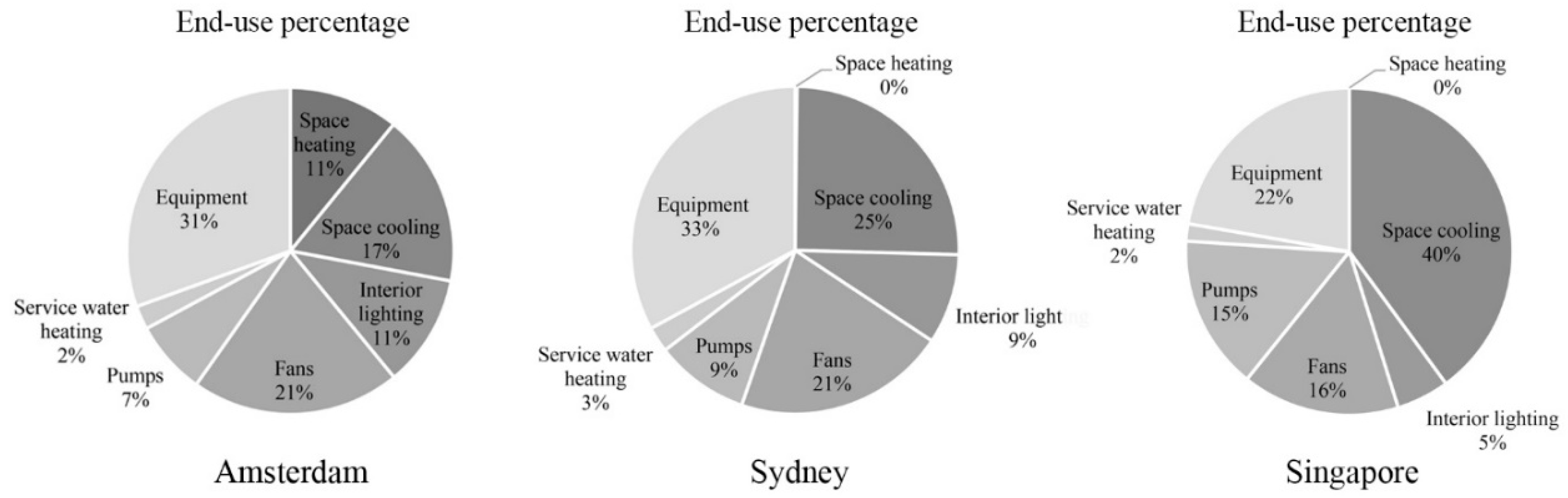
Figure 4.
Building total energy use of 12 plan shapes (window-to-wall ratio (WWR) = 50%) in association with their compactness in Amsterdam (4.77E, 52.30N).
Figure 4.
Building total energy use of 12 plan shapes (window-to-wall ratio (WWR) = 50%) in association with their compactness in Amsterdam (4.77E, 52.30N).
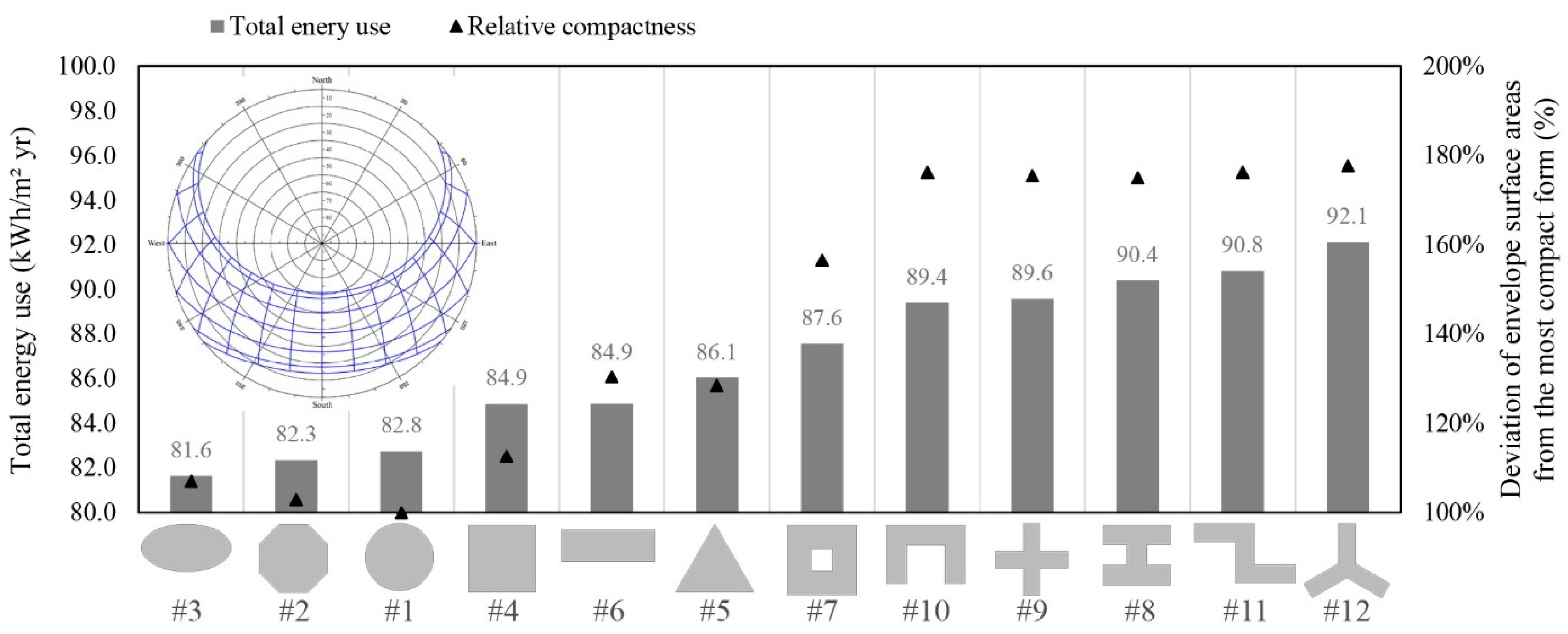
Figure 5.
Building total energy use of 12 plan shapes (WWR = 50%) in association with their compactness in Sydney (151.17E, 33.95S).
Figure 5.
Building total energy use of 12 plan shapes (WWR = 50%) in association with their compactness in Sydney (151.17E, 33.95S).

Figure 6.
Building total energy use of 12 plan shapes (WWR = 50%) in association with their compactness in Singapore (103.98E, 1.37N).
Figure 6.
Building total energy use of 12 plan shapes (WWR = 50%) in association with their compactness in Singapore (103.98E, 1.37N).
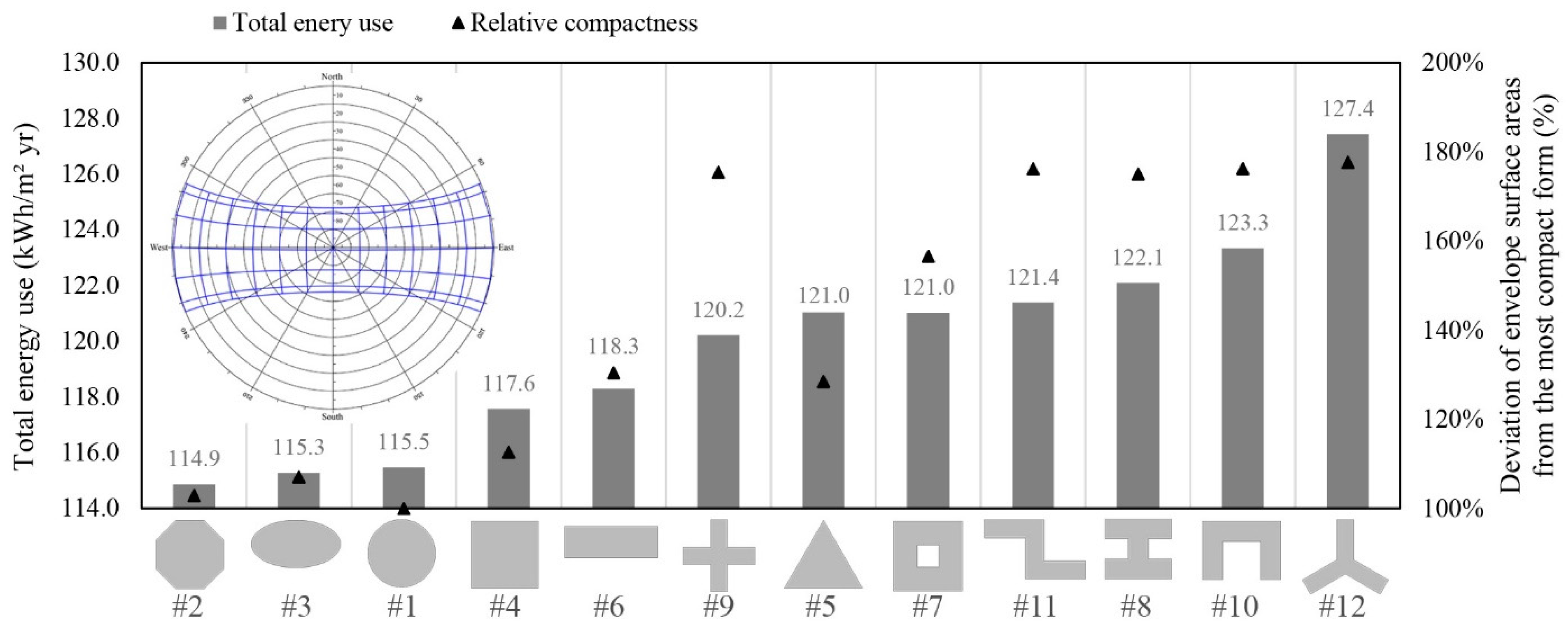
Figure 7.
Building total energy use of seven plan aspect ratios (WWR = 50%) in association to their compactness.
Figure 7.
Building total energy use of seven plan aspect ratios (WWR = 50%) in association to their compactness.

Figure 8.
The energy impact of building orientation on four plan aspect ratios (WWR = 50%) in three climates.
Figure 8.
The energy impact of building orientation on four plan aspect ratios (WWR = 50%) in three climates.

Figure 9.
Recommended window-to-wall ratios for energy efficiency of a 40-storey office building with a deep plan (1:1) and a narrow plan (5:1) in temperate, sub-tropical, and tropical climates.
Figure 9.
Recommended window-to-wall ratios for energy efficiency of a 40-storey office building with a deep plan (1:1) and a narrow plan (5:1) in temperate, sub-tropical, and tropical climates.
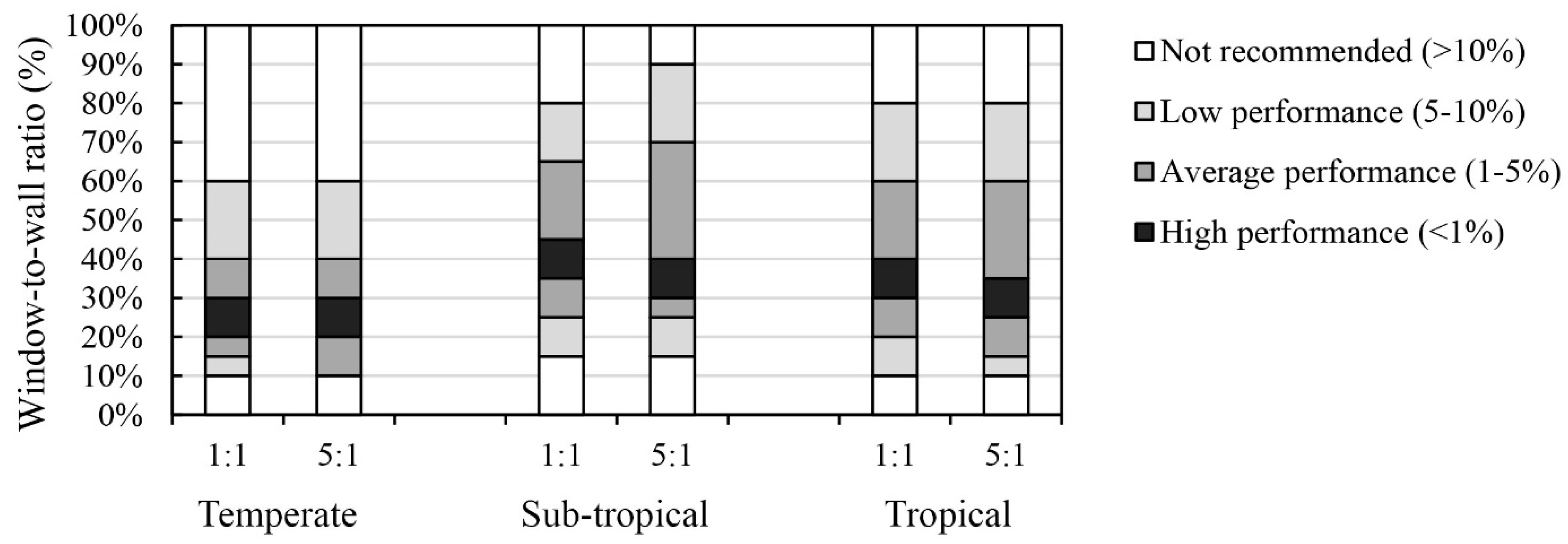
Figure 10.
Sensitivity of different window orientations to a change in the WWR value (ranging from 10% to 90%) in terms of maximum variations in total energy use of a 40-storey office building with a deep plan (a) and a narrow plan (b) in temperate, sub-tropical, and tropical climates.
Figure 10.
Sensitivity of different window orientations to a change in the WWR value (ranging from 10% to 90%) in terms of maximum variations in total energy use of a 40-storey office building with a deep plan (a) and a narrow plan (b) in temperate, sub-tropical, and tropical climates.

Table 1.
Simulation inputs for building’s properties and operation details.
| Building Properties | |
| External wall insulation | U-Value: 0.35 W/m2-K |
| Roof insulation | U-Value: 0.35 W/m2-K |
| Glazing type A 1 | Dbl LoE (e2 = 0.1) Clr 6 mm/13 mm |
| U-Value | Arg |
| SHGC | 1.50 W/m2-K |
| Light transmission | 0.57 |
| 0.74 | |
| Glazing type B 2 | Dbl LoE Spec Sel Clr 6 mm/13 mm |
| U-Value | Arg |
| SHGC | 1.34 W/m2-K |
| Light transmission | 0.42 |
| 0.68 | |
| Window-to-wall ratio | 50% |
| Shading | Blinds (inside) with high-reflectivity slats |
| Shading control type | Glare |
| Maximum allowable glare index | 22 |
| Building Operation Details | |
| HVAC system type | Dual duct VAV |
| Heating | Gas-fired condensing boiler |
| Heating set point temperature | 20 °C |
| Cooling | DOE-2 centrifugal/5.50COP |
| Cooling set point temperature | 24 °C |
| Fan Power | 2 W/l-s |
| Fan total efficiency | 70% |
| Fresh air supply rate | 10 L/s-person |
| Infiltration | 0.5 ac/h |
| Lighting target illuminance | 400 lux |
| Type of lighting | Fluorescent |
| General lighting power density | 3.4 W/m2-100 lux |
| Office equipment gain | 11.77 W/m2 |
| Occupancy density | 0.11 people/m2 |
| Occupancy schedule | Weekdays: 7:00–19:00; weekends: closed |
1 Glazing type A is selected for temperate climates; 2 Glazing type B is selected for sub-tropical and tropical climates.
Table 2.
Sensitivity analysis of building envelope parameters.
| Building Parameter | Climate | Values | Max. Variation (kW h/m2) | ||
| Glazing type | Temperate | A *,max, D min | 4.1 | ||
| Sub-tropical | A max, B *,min, D | 12.6 | |||
| Tropical | A, B *,min, C max, D | 21.8 | |||
| Shading system | Temperate | E min, F max, G * | 11.3 | ||
| Sub-tropical | E, F max, G *, H min | 6.7 | |||
| Tropical | E, F max, G *, H min | 18.1 | |||
| Glazing Description | U-Value | SHGC 1 | TSOL 2 | TVIS 3 | |
| Type A. Dbl LoE (e2 = 0.1) Clr 6 mm/13 mm Arg | 1.50 | 0.57 | 0.47 | 0.74 | |
| Type B. Dbl LoE Spec Sel Clr 6 mm/13 mm Arg | 1.34 | 0.42 | 0.34 | 0.68 | |
| Type C. Dbl Ref-A-H Clr 6 mm/13 mm Arg | 2.26 | 0.22 | 0.13 | 0.18 | |
| Type D. Trp LoE (e2 = e5 = 0.1) Clr 3 mm/13 mm Arg | 0.79 | 0.47 | 0.36 | 0.66 | |
| Shading Description | Control Type | ||||
| Type E. Blinds outside | Solar: (120 W/m2) | ||||
| Type F. Blinds inside | Solar: (120 W/m2) | ||||
| Type G. Blinds inside | Glare: (glare index: 22) | ||||
| Type H. Integrated shading system: overhang 0.5 m + blinds outside | Solar: (120 W/m2) | ||||
* The selected glazing type or shading system; min The design alternative that resulted in minimum energy use; max The design alternative that resulted in maximum energy use; 1 SHGC = solar heat gain coefficient; 2 TSOL = direct solar transmission; 3 TVIS = light transmission
Table 3.
Celsius-based heating and cooling degree days for a base temperature of 18 °C for the year 2002 [16].
Table 3.
Celsius-based heating and cooling degree days for a base temperature of 18 °C for the year 2002 [16].
| City | Climate Type | HDD | CDD |
|---|---|---|---|
| Amsterdam 1 | Temperate | 2759 | 149 |
| Sydney 2 | Sub-tropical | 594 | 896 |
| Singapore 3 | Tropical | 0 | 3657 |
1 Amsterdam Schiphol Airport, The Netherlands (4.77E, 52.30N); 2 Sydney Airport, Australia (151.17E, 33.95S); 3 Singapore Changi Airport, Singapore (103.98E, 1.37N).
Table 4.
Plan shapes isometric views, window distribution, relative compactness and plan depth indicator.
Table 4.
Plan shapes isometric views, window distribution, relative compactness and plan depth indicator.
| Plan Shape | Shape 1 | Shape 2 | Shape 3 | Shape 4 | Shape 5 | Shape 6 |
 |  |  |  |  |  | |
| Share of each façade from the total glazing area (%) |  |  |  |  |  |  |
| Floor plate dimensions | 43.7 m2 | 42.6 m between facades | major axis: 60 minor axis: 32 | 38.7 m between facades | 51.1 m altitude | 67.1 × 22.4 Length × width |
| Relative compactness | 100% | 103% | 107% | 113% | 128% | 130% |
| Plan depth indicator | 47% | 48% | 52% | 52% | 58% | 62% |
| Plan Shape | Shape 7 | Shape 8 | Shape 9 | Shape 10 | Shape 11 | Shape 12 |
 |  |  |  |  |  | |
| Share of each façade from the total glazing area (%) |  |  |  |  |  |  |
| Floor plate dimensions | 14.0 m from void | 46.6 × 42.0 overall length × width 14.0 m between facades | 60.6 × 60.6 overall length × width 14.0 m between facades | 54.4 × 40.4 overall length × width 14.0 m between facades | 76.1 × 45.1 overall length × width 14.0 m between facades | 33.7 m wing lenght 14.0 m between facades |
| Relative compactness | 157% | 175% | 175% | 176% | 176% | 178% |
| Plan depth indicator | 86% | 87% | 87% | 87% | 87% | 87% |
Table 5.
Breakdown of annual energy consumption per conditioned area for 12 plan shapes (WWR = 50%) in Amsterdam (4.77E, 52.30N).
Table 5.
Breakdown of annual energy consumption per conditioned area for 12 plan shapes (WWR = 50%) in Amsterdam (4.77E, 52.30N).
| Plan Shape | Breakdown of Annual Total Energy Demand | Annual Total Energy Demand | ||||
|---|---|---|---|---|---|---|
| Heating/Conditioned Area (kW h/m2) | Cooling/Conditioned Area (kW h/m2) | Lighting/Conditioned Area (kW h/m2) | Fan/Conditioned Area (kW h/m2) | Total/Conditioned Area (kW h/m2) | Percentile Difference (%) | |
| Shape 1 | 15.1 | 22.5 | 17.9 | 27.3 | 82.8 | 1.4% |
| Shape 2 | 15.2 | 22.6 | 17.1 | 27.4 | 82.3 | 0.9% |
| Shape 3 ® | 14.9 | 22.5 | 17.2 | 27.0 | 81.6 | - |
| Shape 4 | 15.2 | 23.5 | 17.5 | 28.7 | 84.9 | 4.0% |
| Shape 5 | 15.6 | 24.3 | 16.4 | 29.7 | 86.1 | 5.4% |
| Shape 6 | 15.5 | 24.2 | 15.8 | 29.4 | 84.9 | 4.0% |
| Shape 7 | 18.5 | 24.1 | 14.6 | 30.5 | 87.6 | 7.3% |
| Shape 8 | 19.2 | 24.4 | 15.6 | 31.2 | 90.4 | 10.7% |
| Shape 9 | 19.7 | 24.6 | 13.9 | 31.4 | 89.6 | 9.7% |
| Shape 10 | 19.5 | 24.3 | 14.6 | 31.0 | 89.4 | 9.5% |
| Shape 11 | 18.5 | 25.8 | 14.0 | 32.6 | 90.8 | 11.2% |
| Shape 12 | 18.9 | 26.0 | 14.4 | 32.9 | 92.1 | 12.8% |
® Reference (the most efficient design option).
Table 6.
Breakdown of annual energy consumption per conditioned area for 12 plan shapes (WWR= 50%) in Sydney (151.17E, 33.95S).
Table 6.
Breakdown of annual energy consumption per conditioned area for 12 plan shapes (WWR= 50%) in Sydney (151.17E, 33.95S).
| Plan Shape | Breakdown of Annual Total Energy Demand | Annual Total Energy Demand | ||||
|---|---|---|---|---|---|---|
| Heating/Conditioned Area (kW h/m2) | Cooling/Conditioned Area (kW h/m2) | Lighting/Conditioned Area (kW h/m2) | Fan/Conditioned Area (kW h/m2) | Total/Conditioned Area (kW h/m2) | Percentile Difference (%) | |
| Shape 1 | 0.4 | 33.5 | 13.6 | 27.6 | 75.2 | 4.5% |
| Shape 2 | 0.4 | 33.6 | 12.8 | 27.7 | 74.6 | 3.7% |
| Shape 3 ® | 0.3 | 32.3 | 12.7 | 26.5 | 72.0 | - |
| Shape 4 | 0.4 | 34.2 | 12.6 | 28.4 | 75.7 | 5.1% |
| Shape 5 | 0.4 | 35.8 | 13.5 | 30.1 | 79.8 | 10.9% |
| Shape 6 | 0.3 | 32.8 | 11.7 | 28.0 | 72.8 | 1.2% |
| Shape 7 | 0.5 | 36.0 | 11.8 | 30.1 | 78.4 | 9.0% |
| Shape 8 | 0.5 | 36.3 | 11.3 | 30.5 | 78.5 | 9.1% |
| Shape 9 | 0.6 | 36.9 | 11.4 | 31.1 | 80.0 | 11.1% |
| Shape 10 | 0.5 | 37.1 | 10.7 | 31.3 | 79.6 | 10.5% |
| Shape 11 | 0.4 | 35.9 | 10.6 | 30.2 | 77.0 | 7.0% |
| Shape 12 | 0.4 | 39.1 | 10.3 | 33.5 | 83.3 | 15.7% |
® Reference (the most efficient design option).
Table 7.
Breakdown of annual energy consumption per conditioned area for 12 plan shapes (WWR = 50%) in Singapore (103.98E, 1.37N).
Table 7.
Breakdown of annual energy consumption per conditioned area for 12 plan shapes (WWR = 50%) in Singapore (103.98E, 1.37N).
| Plan Shape | Breakdown of Annual Total Energy Demand | Annual Total Energy Demand | ||||
|---|---|---|---|---|---|---|
| Heating/Conditioned Area (kW h/m2) | Cooling/Conditioned Area (kW h/m2) | Lighting/Conditioned Area (kW h/m2) | Fan/Conditioned Area (kW h/m2) | Total/Conditioned Area (kW h/m2) | Percentile Difference (%) | |
| Shape 1 | 0.0 | 75.4 | 11.7 | 28.4 | 115.5 | 0.5% |
| Shape 2 ® | 0.0 | 75.5 | 10.8 | 28.6 | 114.9 | - |
| Shape 3 | 0.0 | 75.5 | 11.3 | 28.4 | 115.3 | 0.4% |
| Shape 4 | 0.0 | 76.7 | 11.3 | 29.5 | 117.6 | 2.4% |
| Shape 5 | 0.0 | 79.0 | 10.4 | 31.6 | 121.0 | 5.4% |
| Shape 6 | 0.0 | 77.8 | 10.2 | 30.3 | 118.3 | 3.0% |
| Shape 7 | 0.0 | 79.0 | 10.6 | 31.4 | 121.0 | 5.4% |
| Shape 8 | 0.0 | 80.1 | 9.7 | 32.3 | 122.1 | 6.3% |
| Shape 9 | 0.0 | 79.6 | 8.7 | 31.9 | 120.2 | 4.7% |
| Shape 10 | 0.0 | 81.0 | 9.2 | 33.2 | 123.3 | 7.4% |
| Shape 11 | 0.0 | 80.5 | 8.7 | 32.2 | 121.4 | 5.7% |
| Shape 12 | 0.0 | 82.9 | 9.8 | 34.8 | 127.4 | 11.0% |
® Reference (the most efficient design option).
Table 8.
Plan aspect ratios and the results of building energy performance in three climates.
| Plan Aspect Ratio | 1:1 | 2:1 | 3:1 | 4:1 | 5:1 | 8:1 | 10:1 |
|---|---|---|---|---|---|---|---|
| Building shape |  |  |  |  |  |  |  |
| Share of each façade from the total glazing area (%) |  |  |  |  |  |  |  |
| Floor plate dimensions length × width | 38.7 × 38.7 m | 54.8 × 27.4 m | 67.1 × 22.4 m | 77.5 × 19.4 m | 86.6 × 17.3 m | 109.5 × 13.7 m | 122.5 × 12.2 m |
| Relative compactness | 100% | 120% | 130% | 140% | 150% | 180% | 197% |
| Plan depth indicator | 52% | 56% | 62% | 68% | 74% | 89% | 98% |
Table 9.
Recommended WWR value for different orientations and climates in which the deviation of total energy use is smaller than 1% from the optimal value in each orientation.
Table 9.
Recommended WWR value for different orientations and climates in which the deviation of total energy use is smaller than 1% from the optimal value in each orientation.
| Climate Type/Plan Aspect Ratio | Temperate | Sub-Tropical | Tropical | ||||
|---|---|---|---|---|---|---|---|
| 1:1 | 5:1 | 1:1 | 5:1 | 1:1 | 5:1 | ||
| Recommended WWR value (%) | North | 10–90 | 10–70 | 10–15 | 15–40 | 10–50 | 10–35 |
| East | 35–60 | No glazing | 10–20 | No glazing | 10–20 | No glazing | |
| South | 65–75 | 25–35 | 10–70 | 10–40 | 10–80 | 10–55 | |
| West | 10–15 | No glazing | 10–20 | No glazing | 10–20 | No glazing | |
Table 10.
Early stage design considerations for energy efficiency of high-rise office buildings.
| Temperate | Sub-Tropical | Tropical | ||||||||||||||||||||||
| Plan shape | A | B | C | D | A | B | C | D | A | B | C | D | ||||||||||||
| <1% | Ellipse | + | + | Ellipse | + | + | Octagon | + | + | |||||||||||||||
| Octagon | + | + | Ellipse | + | + | |||||||||||||||||||
| Circle | + | + | ||||||||||||||||||||||
| 1–5% | Circle | + | + | Rectangle | + | Square | + | + | ||||||||||||||||
| Square | + | + | Octagon | + | + | Rectangle | + | |||||||||||||||||
| Rectangle | + | Circle | + | + | + shape | + | ||||||||||||||||||
| 5–10% | Triangle | Square | + | + | Triangle | |||||||||||||||||||
| Atrium | + | Z shape | + | Courtyard | + | |||||||||||||||||||
| U shape | + | Courtyard | + | Z shape | + | |||||||||||||||||||
| + shape | + | H shape | + | H shape | + | |||||||||||||||||||
| U shape | + | |||||||||||||||||||||||
| >10% | H shape | + | U shape | + | Y shape | + | ||||||||||||||||||
| Z shape | + | Triangle | ||||||||||||||||||||||
| Y shape | + | + shape | + | |||||||||||||||||||||
| Y shape | + | |||||||||||||||||||||||
| MD (%) | 12.8 | 15.7 | 11.0 | |||||||||||||||||||||
| Plan aspect ratio | ||||||||||||||||||||||||
| <1% | 1:1, 2:1, 3:1 | 3:1, 4:1 | 1:1, 2:1, 3:1 | |||||||||||||||||||||
| 1–5% | 4:1, 5:1 | 1:1, 2:1, 5:1, 8:1 | 4:1, 5:1 | |||||||||||||||||||||
| 5–10% | 8:1 | 10:1 | 8:1, 10:1 | |||||||||||||||||||||
| >10% | 10:1 | --- | --- | |||||||||||||||||||||
| MD (%) | 12.4 | 6.0 | 8.8 | |||||||||||||||||||||
| Plan orientation | ||||||||||||||||||||||||
| 1:1 | 3:1 | 5:1 | 10:1 | 1:1 | 3:1 | 5:1 | 10:1 | 1:1 | 3:1 | 5:1 | 10:1 | |||||||||||||
| <1% | 0° | 0° | 0° | 0° | 0° | 0° | 0° | 0° | 0° 45° | 0° 45° | 0° | 0° | ||||||||||||
| 1–5% | 45° | 135° 45° | 135° | 45° | --- | --- | --- | --- | 135° 45° | 45° 135° 90° | 45° | |||||||||||||
| 5–10% | --- | 90° | 45° 90° | 135° | --- | 45° 135° | --- | --- | --- | --- | --- | 135° 90° | ||||||||||||
| >10% | --- | --- | --- | 45° 90° | --- | 90° | 45° 135° 90° | 45° 135° 90° | --- | --- | --- | --- | ||||||||||||
| MD (%) | 1.2 | 5.6 | 8.4 | 15.1 | 2.1 | 12.3 | 20.4 | 32.0 | 0.7 | 2.8 | 4.7 | 7.9 | ||||||||||||
| WWR (%): deep plan (1:1) | ||||||||||||||||||||||||
| N | E | S | W | N | E | S | W | N | E | S | W | |||||||||||||
| <1% | 10–90 | 35–60 | 65–75 | 10–15 | 10–15 | 10–20 | 10–70 | 10–20 | 10–50 | 10–20 | 10–80 | 10–20 | ||||||||||||
| 1–5% | --- | 10–35 60–90 | 10–65 75–90 | 15–90 | 15–50 | 20–90 | 70–90 | 20–90 | 50–90 | 20–90 | 80–90 | 20–90 | ||||||||||||
| 5–10% | --- | --- | --- | --- | 50–80 | --- | --- | --- | --- | --- | --- | --- | ||||||||||||
| >10% | --- | --- | --- | --- | 80–90 | --- | --- | --- | --- | --- | --- | --- | ||||||||||||
| MD (%) | 0.5 | 2.8 | 1.8 | 4.5 | 11.3 | 2.9 | 1.1 | 3.1 | 2.9 | 3.3 | 1.1 | 3.0 | ||||||||||||
| WWR (%): narrow plan (5:1) | ||||||||||||||||||||||||
| N | E | S | W | N | E | S | W | N | E | S | W | |||||||||||||
| <1% | 10–70 | --- | 25–35 | --- | 15–40 | --- | 10–40 | --- | 10–35 | --- | 10–55 | --- | ||||||||||||
| 1–5% | 70–90 | --- | 10–25 35–55 | --- | 10–15 40–75 | --- | 40–90 | --- | 35–70 | --- | 55–90 | --- | ||||||||||||
| 5–10% | --- | --- | 55–85 | --- | 75–90 | --- | --- | --- | 70–90 | --- | --- | --- | ||||||||||||
| >10% | --- | --- | 85–90 | --- | --- | --- | --- | --- | --- | --- | --- | --- | ||||||||||||
| MD (%) | 3.0 | --- | 10.3 | --- | 6.8 | --- | 5.2 | --- | 8.6 | --- | 3.2 | --- | ||||||||||||
Energy efficiency of design options: ![Sustainability 09 00623 i039]() <1% (remarkable energy saving);
<1% (remarkable energy saving); ![Sustainability 09 00623 i040]() 1–5% (average energy saving);
1–5% (average energy saving); ![Sustainability 09 00623 i041]() 5–10% (low energy saving);
5–10% (low energy saving); ![Sustainability 09 00623 i042]() >10% (not recommended). A: High space efficiency; B: Aerodynamic form; C: Narrow plan (NV & daylight access); D: Less material use for external envelope; MD: Maximum deviation; N: North orientation; E: East orientation; S: South orientation; W: West orientation.
>10% (not recommended). A: High space efficiency; B: Aerodynamic form; C: Narrow plan (NV & daylight access); D: Less material use for external envelope; MD: Maximum deviation; N: North orientation; E: East orientation; S: South orientation; W: West orientation.
 <1% (remarkable energy saving);
  1–5% (average energy saving);
  5–10% (low energy saving);
  >10% (not recommended). A: High space efficiency; B: Aerodynamic form; C: Narrow plan (NV & daylight access); D: Less material use for external envelope; MD: Maximum deviation; N: North orientation; E: East orientation; S: South orientation; W: West orientation.
© 2017 by the authors. Licensee MDPI, Basel, Switzerland. This article is an open access article distributed under the terms and conditions of the Creative Commons Attribution (CC BY) license (http://creativecommons.org/licenses/by/4.0/).
Share and Cite
MDPI and ACS Style
Raji, B.; Tenpierik, M.J.; Van den Dobbelsteen, A. Early-Stage Design Considerations for the Energy-Efficiency of High-Rise Office Buildings. Sustainability 2017, 9, 623. https://doi.org/10.3390/su9040623
AMA Style
Raji B, Tenpierik MJ, Van den Dobbelsteen A. Early-Stage Design Considerations for the Energy-Efficiency of High-Rise Office Buildings. Sustainability. 2017; 9(4):623. https://doi.org/10.3390/su9040623
Chicago/Turabian StyleRaji, Babak, Martin J. Tenpierik, and Andy Van den Dobbelsteen. 2017. "Early-Stage Design Considerations for the Energy-Efficiency of High-Rise Office Buildings" Sustainability 9, no. 4: 623. https://doi.org/10.3390/su9040623
Note that from the first issue of 2016, this journal uses article numbers instead of page numbers. See further details here.