1. Introduction
The growing energy revolution towards renewable power sources requires the decoupling of the availability of wind and solar energy and its demand, in order to grant stability to the grid [
1]. One option for energy storage is lithium-ion batteries, due to their high coulombic efficiency and energy density [
2,
3]. These properties have already led to a widespread adoption of lithium-ion technology in mobile applications. However, there is also an increasing demand for lithium-ion batteries for stationary energy storage, for example, as home storage for self-generated photovoltaic energy [
4].
The overall ecological balance of renewable energies is significantly dependent on the environmental sustainability of the associated energy storage technology. Despite the superior operational characteristics of lithium-ion batteries, their current manufacturing usually demands the use of toxic organic solvents such as
N-methyl-2-pyrrolidone (NMP) [
5,
6]. During cathode drying, gaseous NMP has to be removed from the exhaust by costly and energy-intensive combustion or condensation. These facts severely influence the ecological balance. Replacing organic solvents with water would better facilitate battery production processes and maintain the favorable, environmentally-friendly nature of renewable energies [
7].
When lithium-ion batteries are used for stationary energy storage in the commercial, and especially in the private sector, high levels of operational safety and reliability are essential. The battery safety depends, to a great extent, on the used cathode active material. A cathode material which meets these requirements is LiFePO
4 (LFP). It provides intrinsic safety [
8,
9,
10], high tolerance towards abuse [
11] and is furthermore, economically friendly. These characteristics make LiFePO
4 an appropriate material for sustainable battery production, in general, and for safety-oriented home storage applications, in particular.
However, despite the many advantages associated with LiFePO
4 it has a poor intrinsic electric conductivity of 10
−9 S∙cm
−1 [
12,
13]. In order to overcome this disadvantage, the particle size of LiFePO
4 is reduced to the nano-scale which leads to a large specific surface and short diffusion length [
8,
14,
15]. Further improvement of electrochemical performance is reached by standard carbon coating of LiFePO
4 particles.
The low bulk density which is correlated with nano-sized particles can be increased by the agglomeration of single nano-sized particles. The obtained secondary agglomerates combine the advantages of nano-sized particles and the higher bulk density of micro-sized ones. Higher bulk densities allow for producing cathodes with higher material- and energy-density and improved long-term cycling [
16,
17].
For a successful, economically-friendly water-based manufacturing process of LiFePO
4 cathodes, it is important that the active material is compatible with water as a solvent. LiFePO
4 and its behavior upon contact with moisture and water has been studied in recent years. It is reported that in direct contact with water, active lithium is lost by the formation of a surface layer consisting of Li
3PO
4, which reduces the energy density of LiFePO
4. This might also cause slight changes to lattice parameters which could be observable in diffraction experiments. However, this effect can be limited by reducing the period of water exposure [
18]. It has also been found that carbon coating is not fully stable in water and partially detaches from the LiFePO
4 particle surface [
19]. Notably, though, carbon coating has a protective function and prevents LiFePO
4 from accelerated ageing [
20]. Studies have shown that LiFePO
4 cathodes can reach a good electrochemical performance after being processed in water [
21]. The advantages of water-based elastomer binders in terms of cathode homogeneity and battery performance in comparison to solvent-based systems have also been recorded [
22].
This article will evaluate the influence of the LiFePO4 morphology on water-based processing, aspects of ageing, electrochemical characteristics and the suitability for environmentally-friendly battery production.
2. Experiment
A development-grade carbon coated LiFePO4 (LFP) with two different morphologies was used for processing water- and organic-based cathodes. The first LiFePO4 sample consisted of sub-micron single particles (referred to as PP) and the second sample consisted of PP agglomerated to spheres (referred to as SA).
The samples PP and SA were processed as water- and solvent-based slurries resulting in four different cathodes. The solvent which was used for the slurry preparation is indexed in the respective cathode identification, such as PPH2O. If no solvent is indicated (e.g., “PP” or “SA”), then the cathodes prepared with both solvents are meant.
For water-based slurries carboxymethyl cellulose (CMC MAC 200 HC, Sunrose, Nippon Paper Industries Co., Ltd., Tokyo, Japan) was dissolved in water and mixed with carbon black (Super C65, TIMCAL, Düsseldorf, Germany) and SBR (AY9391, ZEON, Tokyo, Japan) and PP or SA, respectively. All constituents were dispersed in a dissolver (DISPERMAT, VMA GETZMANN GmbH, Reichshof, Germany) for 30 min at 3000 rpm. The final solid content fractions were 88.6 wt % PP or SA, 6.0 wt % carbon black, 3.6 wt % SBR and 1.8 wt % CMC.
Slurries based on an organic solvent were obtained by dissolving PVDF (Solef 5130, Solvay) in N-methyl-2-pyrrolidone (NMP, Roth, Karlsruhe, Germany) and mixed with PP or SA and carbon black. Dispersing the constituents was conducted as described for water-based slurries. The final solid content fractions were 88.0 wt % PP or SA, 6.0 wt % PVDF and 6.0 wt % carbon black.
After dissolution, the slurries were degassed in a planetary centrifugal mixer (THINKY, Laguna Hills, USA) for 4 min at 2200 rpm and then cast on a carbon-coated aluminum foil and dried under vacuum at 110 °C for at least 12 h.
The obtained cathodes were then assembled to full-cells by using an inorganic-filled PVDF separator and anodes composed of graphite (MAG-D, Hitachi Chemical Co., Ltd, Tokyo, Japan) (91.4 wt %), conductive carbon (Super C65, TIMCAL, Düsseldorf, Germany) (4.0 wt %), SBR (BM-400B, ZEON, Tokyo, Japan) (2.8 wt %) and CMC (MAC 200 HC, Sunrose, Nippon Paper Industries Co., Ltd., Tokyo, Japan) (1.8 wt %)). For electrolyte, 1.5 mL of LP50 (1 M LiPF6 in EC:EMC (1:1 wt %), BASF) was used. At least four full-cells were assembled of each cathode foil. The average areal capacity loading of the cathodes was 1.1 ± 0.1 mAh·cm−2. The areal capacity balancing of anode: cathode was 0.9.
The full-cells were formed at room temperature with a charge rate of C/10 up to 3.65 V with a potential hold until the current dropped below C/20 and a discharge rate of C/10 to 2.0 V.
The subsequent C-rate test was carried out with a charge rate of C/10, C/5, C/2, 1 C, 2 C and 5 C by charging with the applied C-rate of up to 3.65 V with a potential hold until the current dropped below C/20 and discharged with the corresponding C-rate to 2.0 V. Each C-rate charge and discharge was repeated three times. For each full-cell, the different C-rate currents were calculated on the basis of the discharge capacity of the second cycle. The long-term capacity fading of full-cells was examined by charging at 1 C to 3.65 V with a potential hold until the current dropped below C/20 and discharged to 2.0 V at 1 C for 500 cycles.
A field emission scanning electron microscope (FE-SEM) (Merlin Compact, Zeiss, Oberkochen, Germany) was used to take micrographs of the prepared cathodes.
The lattice parameters of the pristine PP were analyzed by using neutron powder diffraction analysis. Elastic coherent neutron scattering experiments were performed on the high-resolution powder diffractometer SPODI at the neutron source FRM II at the Heinz Maier-Leibnitz Zentrum (Garching, Germany) [
23]. Monochromatic neutrons (λ = 1.5482 Å) were obtained at a 155° take-off angle using the (551) reflection of a vertically-focused composite Ge monochromator. A vertical position-sensitive multidetector (300 mm effective height) consisting of 80
3He tubes and covering a 2θ angular range of 160 deg. was used for data collection. Measurements were performed in Debye-Scherrer geometry. The powder sample (ca. 2 cm
3) was placed into a vanadium can 13 mm in diameter with a wall as thin as 0.15 mm. For minimization of the preferred orientation effect on the diffraction pattern, the sample was constantly rotated during data collection.
Additionally, the crystal structures of PP and SA in the prepared cathodes were studied by means of X-ray diffraction (XRD) (Empyrean, PANalytical, Almelo, Netherlands) using transmission geometry and Mo-K
α1/α2 radiation (λ = 0.70932 Å, U = 55 kV, I = 40 mA, ratio K
α1/K
α2 ≈ 0.30–0.33) and a step size of 0.008°(2Ө). Beam divergence was limited to 0.02° with Soller Slits and a 0.25° divergence slit. All data analysis was performed by
Rietveld refinements using the Highscore software package [
24].
Rietveld refinements were carried out using
Thompson-Cox-Hastings pseudo-
Voigt function [
25] and
Finger-Cox-Jephcoat profile asymmetry treatment to fit the data [
26]. The aluminium current collector phase was treated with a
Pawley-Fit [
27].
3. Results and Discussion
To analyze and compare the influence of water- and NMP-based slurry preparation on the structural properties of LFP, X-ray diffraction was applied. In order to quantify the influence of both applied solvents, additional lattice parameters of a pristine PP powder sample were determined via high-resolution neutron diffraction. It was only carried out for pristine PP material in order to verify the lithium content of the pristine samples, due to the better contrast of neutrons for lithium compared to XRD. For comparison, the neutron and X-ray diffraction data in
Figure 1 are plotted vs. d-spacing.
For the neutron data, 7 h acquisition time was used and a comparable 8 h time was used for the first two XRD measurements of cathodes. A variation of time (1 h and 63 h) also proved that sufficient data quality is already obtained after 1 h and the 63 h data set shows that no additional reflections have been overlooked. Different peak intensities for identical reflections in the neutron and XRD plots are due to the different scattering cross section of the two methods. Also, the additional K
α2-reflection is visible in the XRD plots as a shoulder right to the K
α1-peak. The results of the structural studies and lattice parameters from the
Rietveld refinement of the LFP-phase are given in
Table 1.
The results of X-ray and neutron diffraction show that neither water nor NMP have any significant influence on the structure of PP and SA in terms of slurry preparation and cathode coating. The highest deviation with a value of 0.0017 Å between the pristine and processed PP can be found for parameter
a when it is processed in water (PP
NMP). For SA the largest difference is observed for the lattice parameter
c with a value of 0.0014 Å after water-based processing (SA
H2O). However, it has to be taken into account that deviations in the range of ≈ 0.001 Å have to be interpreted carefully since they are in the range of measurement inaccuracy [
28,
29,
30,
31]. This applies in particular in the present case, as no systematic tendency in the change of lattice parameters can be observed and negligible variations seem to be random. Thus, we regard the active material as such to be non-sensitive to water and stable during slurry preparation.
The visual appearance and quality of the prepared cathodes was evaluated via FE-SEM and the obtained micrographs are shown in
Figure 2.
As seen in
Figure 2a,b, the constituents of the PP
H2O and PP
NMP cathodes show an optimum, homogeneous distribution.
Figure 2c,d shows the structure of the SA
H2O and SA
NMP cathodes. The secondary agglomerates of the SA
H2O cathode in
Figure 2c are homogeneously covered with a thin layer of binder and incorporated conductive carbon and primary particles of LFP. The shape of the underlying secondary agglomerates is, however, visible. The primary particles on the cathode surface are not necessarily detached from the secondary agglomerates as a result of mechanic stress during slurry preparation. They might also represent a small fraction of residual particles which were not bound in secondary agglomerates during the agglomerating process. The SA
NMP cathode in
Figure 2d has a different appearance in comparison to the SA
H2O cathode. The constituents are distributed homogeneously, but some secondary agglomerates on the surface are only partially covered with conductive carbon. This can be caused by a longer period of drying of NMP-based cathodes after the coating step due to the higher boiling point of NMP. In the wet state, the slurry constituents are still movable and might separate to a certain extent depending on the period of drying. Parameters such as solid and solvent content in the slurry, electrode thickness, coating speed or the electrode drying procedure were not varied during the cathode preparation and are therefore assumed to have no influence on different cathode appearances.
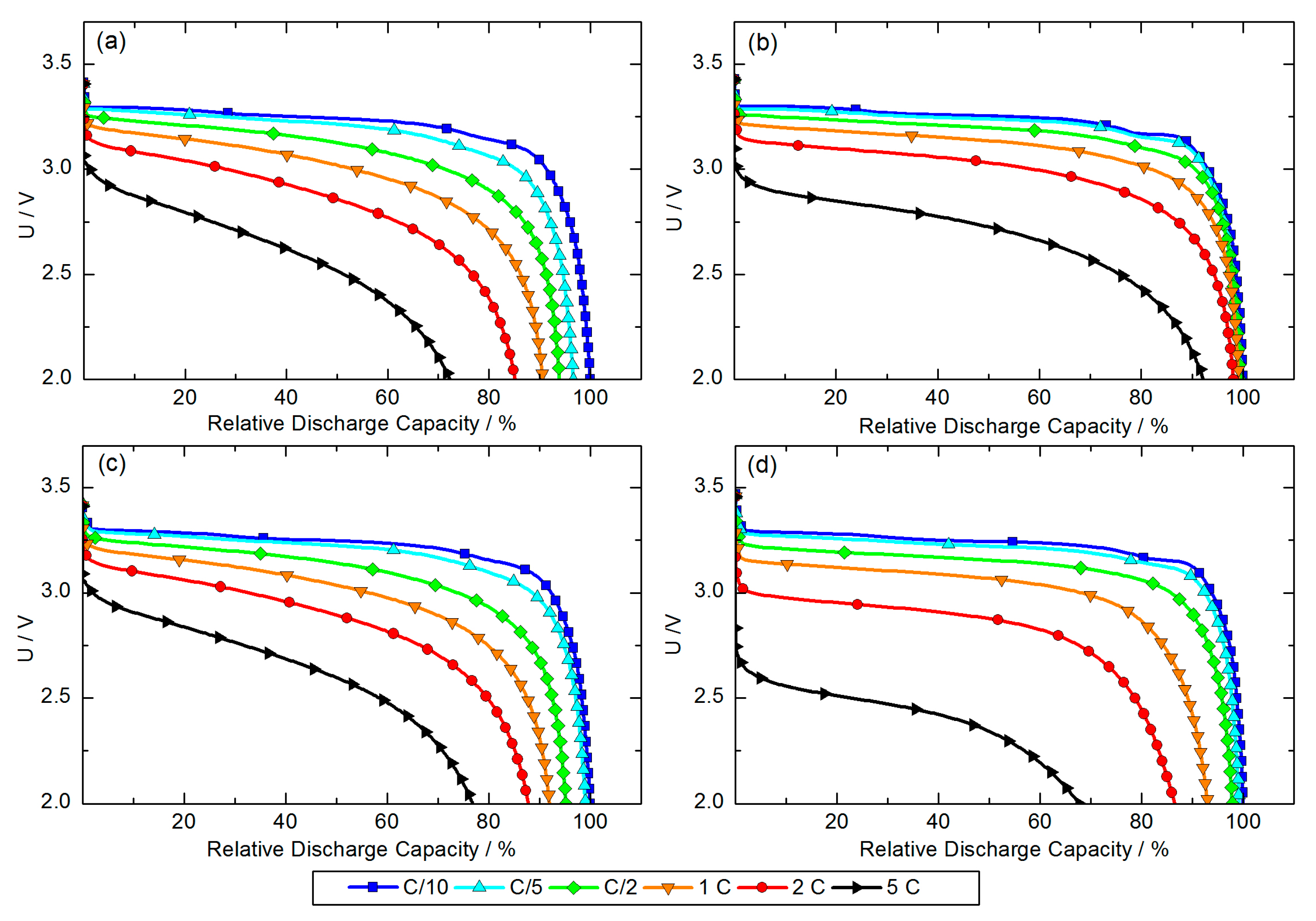
After the formation step the C-rate performance test was carried out for full-cells prepared with all four different cathodes. The obtained discharge curves are shown in
Figure 3. The highest observed specific discharge capacity (at C/10) was set to 100% for each full-cell and all other observed discharge capacities were set in relative relation to this value. In consideration of the initial capacity loss caused by the formation of the SEI layer, the areal capacities (at C/10) of PP
H2O, PP
NMP, SA
H2O and SA
NMP were 0.98, 0.98, 0.92 and 0.94 mAh·cm
−2, respectively.
Comparing the discharge curves of full-cells assembled with PP
H2O and PP
NMP cathodes (
Figure 3a,b) shows a distinct difference in C-rate capability. The discharge capacity of the full-cell assembled with a PP
H2O cathode decreases constantly with an increased C-rate, but still reaches a reasonable 72% of the discharge capacity observed at C/10. In contrast full-cells assembled with PP
NMP cathodes show more or less no decrease of discharge capacity for C-rates up to 2 C. At a 5 C-rate, full-cells still reach 92% relative discharge capacity, which demonstrates a very good C-rate capability. The difference between PP
H2O and PP
NMP cathodes cannot be explained by the cathode structure observed via FE-SEM because for both solvents, a homogeneous distribution of constituents was confirmed.
The discharge curves of full-cells assembled with SA
H2O and SA
NMP cathodes (
Figure 3c,d) appear similar for C-rates from C/10–1 C. For both full-cells, approximately 92% of the discharge capacity observed at C/10 is reached when cells are discharged at a 1 C-rate. Differences in discharge behavior become significant at a 2 C-rate. Both full-cells reach almost the same relative discharge capacity (88% for the SA
H2O-based full-cell, 87% for the SA
NMP-based full-cell), but the initial voltage drops (IR-drop) at the beginning of discharge differ. The voltage of the full-cell assembled with a SA
H2O cathode drops down to approximately 3.2 V while it drops down to approximately 3.0 V in the case of the full-cell assembled with a SA
NMP cathode. This difference in IR-drop and relative discharge capacity becomes more distinct at a 5 C-rate. The reason for the lower internal resistance of the full-cell assembled with a SA
H2O cathode is very likely the better distribution of cathode constituents as it was observed via FE-SEM.
In the case of full-cells assembled with PPH2O or PPNMP cathodes, we do not see such a difference in IR-drop at higher C-rates, but the voltage-curve of the full-cell assembled with a PPNMP cathode drops slower over the discharge process.
An explanation for the different discharge characteristics of PPNMP cathodes and both SAH2O and SANMP cathodes, is the morphology. Each secondary agglomerate of SA itself represents a small-scale heterogeneity of the cathode coating, but for an optimum battery performance a highest possible homogeneity of electrode constituents is striven. This can be realized by using PP which leads to a higher C-rate capability. Longer diffusion paths to the inner particles of SA can be seen as a further reason for lower C-rate capability.
The different C-rate capability of PPH2O- and PPNMP-based full-cells can be caused by partial detachment of carbon coating caused by water-based processing, thereby resulting in a higher internal resistance and lower discharge capacity at increased C-rates. An influence of the areal capacity of the cathodes is unlikely since it varies only in a narrow range of 0.06 mAh·cm−2 and thus might not significantly influence the C-rate performance of each battery.
A difference in internal resistance was also found in the charge behavior of PP- and SA-based full-cells.
Figure 4 shows that in full-cells assembled with the SA
H2O, SA
NMP and PP
NMP cathodes, the transfer of the charge was 93.4–94.3% during the constant current phase (CC-phase) and the residual charge occurred during the constant voltage phase (CV-phase). Thus, these full-cells show nearly the same charge characteristics. In contrast, full-cells assembled with PP
H2O cathodes transferred 74.1% and 25.9% during the CC- and CV-phase, respectively.
An explanation, therefore, is that the upper cutoff voltage of 3.65 V is reached faster due to higher internal resistance in the full-cell assembled with the PPH2O cathode and thus, more charge has to be transferred at a constantly decreasing current during the CV-phase. For SA, no influence of the slurry solvent on the charge behavior was observed.
Figure 5 shows the result of the long-term cycling at a 1 C-rate. The highest specific discharge capacity was reached by full-cells assembled with PP
NMP cathodes (set to 100% in
Figure 5). SA-based full-cells reach 96% relative discharge capacity independently from the solvent used for slurry preparation and their curves are more or less completely overlapped. Full-cells assembled with PP
H2O cathodes reach only 86% relative discharge capacity. This direct comparison of relative discharge capacities shows the strong morphologic influence on the performance of the battery. Slight deviations between the observed capacities at a 1 C-rate in
Figure 3 and
Figure 5 were caused by the fact that for the C-rate test, each battery was individually normalized to 100%, while values for the long-term cycling were obtained by average values of at least four batteries per parameter set and normalization of all average values to the highest observed discharge capacity.
The capacity fading rate of PP-based full-cells is slightly higher. In particular, full-cells assembled with PP
H2O cathodes fade stronger during the first 100 cycles. This is a further indicator for partial detachment of carbon coating caused by water-based slurry preparation. Assuming traces of moisture contamination in the electrolyte, hydrofluoric acid is formed during cycling which can corrode the uncoated surface of PP and dissolute iron atoms from the structure. This causes an increased capacity fading. Complete and intact carbon coating effectively protects the PP surface from corrosion [
20]. Since the difference in fading is less pronounced, we assume only minor detachment of the carbon coating caused by water-based processing.
The lower fading rate of SA-based full-cells leads to a crossing of the capacity curves of PPNMP-based full-cells and SA-based full-cells after approximately 300 cycles. Thus, even if full-cells assembled with PPNMP cathodes show the highest initial discharge capacity, SA-based full-cells feature a better long-term cycling behavior, which comes into effect after 300 cycles.
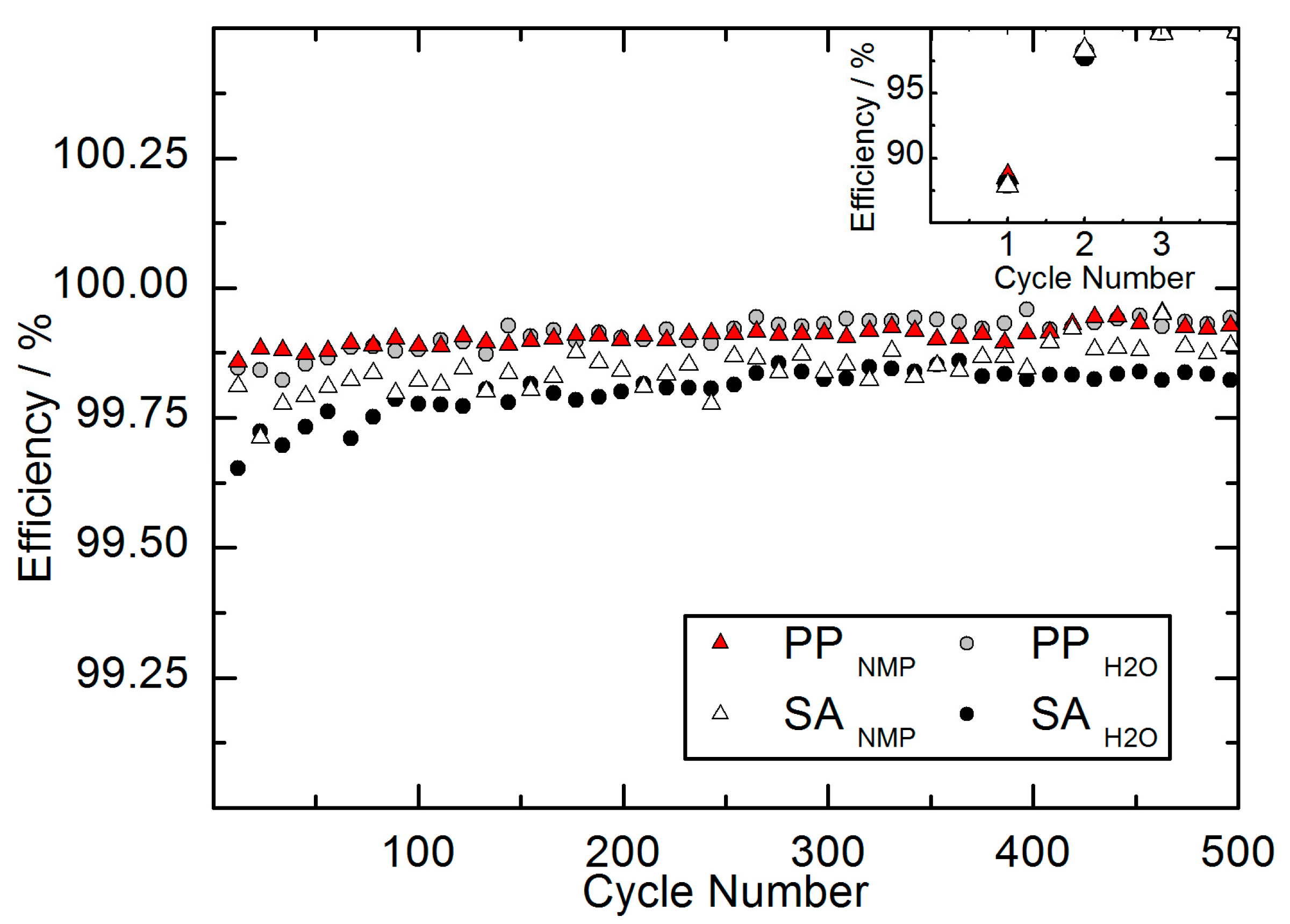
Additionally, the coulomb efficiency was evaluated for the full-cells of long-term cycling. The coulomb efficiency was calculated as the ratio of Q
Discharge/Q
Charge. The coulomb efficiency is illustrated in
Figure 6. The values of each parameter represent the average of the same full-cells used for the long-term cycling.
As seen in the inset of
Figure 6, the coulomb efficiency is reduced in the first cycle. This is caused by the lithium consuming formation of the protective SEI layer on the anodic graphite. The formation of the SEI layer corresponds with a significant irreversible capacity loss (ICL) mainly during the first and second cycle. The observed capacity losses after the formation step were 11.5 ± 0.6%, 11.9 ± 0.9%, 12.1 ± 0.8% and 12.0 ± 0.4% for PP
NMP, PP
H2O, SA
NMP and SA
H2O, respectively. Since the SEI formation mainly takes place during the first cycle, the capacity losses were moderate after the second cycle. Ongoing SEI formation during the second cycle caused capacity losses of 1.7 ± 0.2%, 1.8 ± 0.3%, 1.7 ± 0.2% and 2.2 ± 0.2% for PP
NMP, PP
H2O, SA
NMP and SA
H2O, respectively. The capacity losses during the first two cycles varied only in a narrow range for the different parameter sets and are in good correlation with the analyzed coulomb efficiencies during the first cycles.
Figure 6 also reveals that all full-cells have a reasonable coulomb efficiency above 99.5% during the long-term cycling. A slight, constant increase of coulomb efficiency corresponds with a decreasing capacity fading as shown in
Figure 5. Stronger fading should usually result in lower coulomb efficiency because parasitic processes continue during formation of the new SEI layer. Remarkably, in comparison with the long-term fading we observe a reversed order of coulomb efficiency for the different parameter sets. SA-based full-cells show the lower capacity fading over 500 cycles, but also exhibit the lower coulomb efficiency. In contrast, PP-based full-cells reveal the higher coulomb efficiency but demonstrate stronger fading. One explanation might be the different morphology. Studies have shown that the particle size distribution of active material influences the relation between coulombic efficiency and capacity fading [
32]. A difference in particle size distribution can cause a lower fading and simultaneously lower coulomb efficiency. Since the LFP primary particles analyzed in this study are the same material used for the preparation of secondary agglomerates, the particle size distribution is identical in terms of the particles. But an influence might be caused by an additional particle size distribution obtained by the secondary structure of agglomerates. Additionally, the discussion of coulomb efficiency in the context of capacity fading and battery quality should generally be handled with care. Other factors, such as diffusion-induced stress (DIS) and the capacity ratio of anode:cathode also play a significant role [
33]. Just how far the morphology of the same active material stands in correlation to coulomb efficiency and long-term capacity evolution will be the subject of further, detailed studies.
Taking into account the results of the charge and discharge behaviour and long-term cycling, we come to the following explanation of the differences:
The process time, from the immersion of active material into water to the dried cathodes, was short enough to prevent structural changes of the active material itself. However, during slurry dissolution the active material particles are exposed to high mechanical stress and shear rates. In the case of PP additional contact to water causes a partial detachment of carbon coating. But if primary particles (PP) are agglomerated to spheres (SA) the major fraction of particles is located inside the agglomerates and protected from mechanical stress. The concurrent exposure to water and mechanical stress only takes place on particles at the outer layer of agglomarates and thus a partial detachment of carbon coating can only occur on the surface particles. This effect is negligible since no difference in performance was found at moderate C-rates. Differences occuring at higher C-rates were rather caused by using different binders, and the water-based CMC binder resulted in a favorable performance. The fact that cathodes containing SA did not reach the C-rate performance of PPNMP cathodes is assumed to be caused by longer diffusion paths in the case of SA and a higher cathode homogeneity, which was reached by using PP.


 ,
, 


